analysis of a friction damper system for the new cryogenic...
TRANSCRIPT

Analysis of a Friction Damper System for the New Cryogenic Upper Stage ESC-A
of Ariane 5 with Pro/MECHANICA
1st Pro/MECHANICA User’s Conference at DENC AG Dr. Roland Jakel, Astrium GmbH, Germany

© AstriumFolie 2, Dr. R. Jakel, Astrium IT 64
Table of Contents
Introduction: ESC-A, the New Cryogenic Upper Stage of Ariane 5Friction Damper System SARO for Optimising the Dynamic Behavior of ESC-AAnalysis Tasks performed within Pro/MECHANICA for SARO:– Analysis of the non-linear Friction Damper with
Pro/MECHANICA Motion– Contact Analysis of the Ball Bearings with Pro/MECHANICA
Structure– Modal Analysis of the Complete SARO System with
Pro/MECHANICA VibrationConclusion
ESC-A is being developed by Astrium as prime contractor of CNES, theFrench space agency. CNES is managing the Ariane 5 development for ESA, the European space agency.

© AstriumFolie 3, Dr. R. Jakel, Astrium IT 64
Placement of ESC-A in the Ariane 5 Development
Lift-off mass 746 t 767 t 777 t 790 t
Payloadin GTO
Ariane 5
Ariane 5Versatile(Versatilestorablepropellantstage)
Ariane 5ESC-A(Cryogenic-Aupper stage)
Ariane 5ESC-B(Cryogenic-Bupper stage)
1999 20022001 2005

© AstriumFolie 4, Dr. R. Jakel, Astrium IT 64
Position of SARO friction damper struts
LOx tank suspension by framework of 36 struts
Position of Friction Damper Struts andLOx Tank Suspension in the ESC-A
ESC-A Cryogenic Upper Stage
Design of the Upper Stage ESC-A

© AstriumFolie 5, Dr. R. Jakel, Astrium IT 64
Friction Damper System SARO
SARO = „Système Amortisseur Réservoir Oxygène“
From Launcher System Analysis:– 1st acoustic booster mode can lead to lateral bending modes of
the launcher in case of asymmetric excitation. – Coupling between lateral LOx tank and lateral payload
oscillation exists. – As a consequence, lateral payload response can significantly be
reduced by introducing damping to the LOx tank.
Technical Target of SARO:to provide damping at amplitudes down to 0.1 mm over a distance of approx. 1.5 m at a frequency of 20 Hz under cryogenic temperatures

© AstriumFolie 6, Dr. R. Jakel, Astrium IT 64
Position of Damper Struts

© AstriumFolie 7, Dr. R. Jakel, Astrium IT 64
Design of Friction Damper System

© AstriumFolie 8, Dr. R. Jakel, Astrium IT 64
/ Analysis Tasks
Non-linear analysis of damper Modal analysis of complete system Contact analysis of ball bearings

© AstriumFolie 9, Dr. R. Jakel, Astrium IT 64
Non-Linear Analysis of Damper
Simplifiedanalysis model:
Real damper design*):
*) picture by Jarret
u (t)
FD

© AstriumFolie 10, Dr. R. Jakel, Astrium IT 64
Non-Linear Analysis of Damper
Dissipated energy per cyclefor elastically connected ideal Coulomb friction damper:
⋅
−⋅=ukFuFW D
DD ˆ1ˆ4
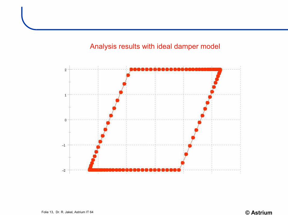
Phase diagram of elastically connected ideal Coulomb friction damper:
High non-linear force-velocity behavior of ideal Coulomb friction damper: x=v
constFD =
Force-velocity behavior used in Motion to prevent numerical instability of ideal damper
x̂
ū
x0 x0
S0
S0
kFD
FDx
FForce-velocity behavior used in Motion to approximate real friction damper
C1C2
C2
FC
FC

© AstriumFolie 11, Dr. R. Jakel, Astrium IT 64
Non-Linear Analysis of Damper
Tricks used in Pro/MECHANICA Motion to model friction damper:
– Damper force was modelled as computed measure with velocity-dependent force:• measure “ideal damper force” = bound(C1v, -FD, FD)• measure “real damper force” = bound(C1v, -FC, FC) + C2v• damper joint axis load was then created of polynomial type
as function of measure– Linear spring used for spring in serial connection to damper– Dissipated energy modelled as measure, evaluation method
“integrated”: measure = damper force x damper velocity– Damper excitation modelled as position drive with cosine
function

© AstriumFolie 12, Dr. R. Jakel, Astrium IT 64
Non-Linear Analysis of Damper
SARO friction damper test results
© AstriumFolie 13, Dr. R. Jakel, Astrium IT 64
Analysis results with ideal damper model

© AstriumFolie 14, Dr. R. Jakel, Astrium IT 64
Analysis results with real damper model

© AstriumFolie 15, Dr. R. Jakel, Astrium IT 64
Non-Linear Analysis of Damper
Comparison of Analysis and Test Results:
Max. Damper Friction Force:Hand analysis with ideal damper: 2 kNPro/MECHANICA analysis with ideal damper: 2 kNPro/MECHANICA analysis with real damper: 2,03 kNTest: 2,07 kN
Dissipated Energy per Cycle:Hand analysis with ideal damper: 0.63 NmPro/MECHANICA analysis with ideal damper: 0.64 NmPro/MECHANICA analysis with real damper: 0.67 NmTest: 0.68 Nm
Remark:Error between ideal and real damper is bigger at other speeds!

© AstriumFolie 16, Dr. R. Jakel, Astrium IT 64
Contact Analysis of Ball Bearings
Used 3D-Model:- 1016 solids- 20 contact regions

© AstriumFolie 17, Dr. R. Jakel, Astrium IT 64
Contact Analysis of Ball Bearings
Methods used to model attachment elements in Pro/MECHANICA Structure:
– half model created (because of slot in bearing race, quarter model was not possible)
– all parts in contact (Aluminium lug, race, ball, bolt, hole in fork end) have been modelled with minimum and maximuminterferences (= 2 models): • if all maximum interferences come together, this is called
“tight fit case” = max. stiffness, but also max. friction moment• if all minimum interferences come together, his is called
“loose fit case” = min. stiffness and min. friction moment– mesh and contact regions created by hand – single path adaptive analysis, one load increment– stiffness of connection was analysed by comparing
displacement of unloaded model (after contact analysis) with displacement of loaded model (tension load at fork end)
– friction moment was estimated by analysing the average contact pressure between ball and race

© AstriumFolie 18, Dr. R. Jakel, Astrium IT 64
Contact Analysis of Ball Bearings
Goal is to reach sufficient stiffness of attachment elements by acceptable stresses in the parts and friction moments in the bearing!
Comparison of analysis results with test for:– stiffness with 6500 N tension load– rotational torque with assuming µ=0,04
Interference[µm]:
MeasuredStiffness[N/m]:
AnalysedStiffness[N/m]:
Measuredtorque[Nm]
Analysedtorque[Nm]
Tightfit:
ball-race: 5race-lug: 31bolt-ball: 16bolt-yoke: 17
1,71 E+8 1,75 E+8 14,9 15,6
Loosefit:
ball-race: 3race-lug: 6bolt-ball: 8bolt-yoke: 8
1,47 E+8 1,55 E+8 9,0 6,3

© AstriumFolie 19, Dr. R. Jakel, Astrium IT 64
Modal Analysis of Complete System
Used 3D Beam-Model:18 beams5 masses2 beam releases

© AstriumFolie 20, Dr. R. Jakel, Astrium IT 64
Modal Analysis of Complete System
Methods used to model SARO struts in Pro/MECHANICA Vibration:– full model created with beam elements and representative cross
sections/stiffnesses– damper modelled with two beam structures (inner and outer
tube) and cross beams to model guiding bearings in damper; beam release used to model moment-free bearing connection
– point masses used to model mass concentrations of flanges or other parts
Comparison of first fundamental bending frequency:– test result: 78,9 Hz– analysis result: 80,6 Hz

© AstriumFolie 21, Dr. R. Jakel, Astrium IT 64
Conclusion
All modules of Pro/MECHANICA gave results, which were in good agreement to the measurements:
Non-Linear Analysis of Damper in Motion:– Error in energy dissipation 2-6 %
Contact Analysis of Ball Bearings in Structure:– Error in stiffness estimation: 2-5 %– Error in friction torque estimation: 5-30 %
(but nature scatters similar for “equivalent” bearings!)
Modal Analysis of Complete System in Vibration:– Error in frequency estimation: 2 %