analysis of /3528lj 7p - ntrs.nasa.gov · analysis of shell-type structures subjected to i ... is...
TRANSCRIPT

/3528LJ ? * 7P
ANALYSIS OF SHELL-TYPE STRUCTURES SUBJECTED TO I
TIME-DEPENDENT MECHANICAL AND THERMAL WADING
A SEMI-ANNUAL STATUS REPORT SUBMITTED TO
NASA-LEWIS RESEARCH CENTER CLEVELAND, OHIO
BY
G. J. Simitses and R. Riff
School of Aerospace Engineering Georgia Institute of Technology
Atlanta, Georgia
April 1988
(NASA GRANT: NAG 3-534)
INTRODUCTION
The objective of the present research is to develop a general mathematical model and solution methodologies for analyz- ing structural response of thin, metallic shell-type structures under large transient, cyclic or static thermomechanical loads. Among the system responses, which are associated with these load conditions, are thermal buckling, creep buckling and ratcheting. Thus, geometric as well as material-type nonlinearities (of high order) can be anticipated and must be considered in the develop- ment of the mathematical model. Furthermore, this must also be accommodated in the solution procedures.
SUMMARY OF PROGRESS
The progress to date has been elaborated upon in an interim scientific report submitted to the sponsor during the summer of 1986, and in a series of semiannual progress reports. The most recent of these is dated October, 1987.
A complete true ab-inito rate theory of kinematics and kine- tics for continuum and curved thin structures, without any res- triction on the magnitude of the strains or the deformation, was formulated. The time dependence and large strain behavior are incorporated through the introduction of the time rates of the
I ~
Y
https://ntrs.nasa.gov/search.jsp?R=19880011284 2018-07-29T04:09:29+00:00Z

metric and curvature in two coordinate systems; a fixed (spatial) one and a convected (material) coordinate system. The relations between the time derivative and the covariant derivatives (gra- dients) have been developed for curved space and motion, so that the velocity components supply the connection between the equa- tions of motion and the time rate of change of the metric and curvature tenors.
The metric tensor (time rate of change) in the convected ma- terial coordinate system is linearly decomposed into elastic and plastic parts. In this formulation, a yield function is assumed, which is dependent on the rate of change of stress, metric, tem- perature, and a set of internal variables. Moreover, a hypoelas- tic law was chosen to describe the thermoelastic part of the de- formation.
A time and temperature dependent viscoplastic model was for- mulated in this convected material system to account for finite strains and rotations. The history and temperature dependence were incorporated through the introduction of internal variables. The choice of these variables, as well as their evolution, was motivated by phenomenological thermodynamic considerations.
The nonisothermal elastic-viscoplastic deformation process was described completely by llthermodynamic state" equations. Most investigators (in the area of viscoplasticity) employ plastic strains as state variables. Our study shows that, in genera1,use of plastic strains as state variables may lead to inconsistencies with regard to thermodynamic considerations. Furthermore, the approach and formulation employed by all previous investigators lead to the condition that all plastic work is completely dis- sipated. This, however, is in contradiction with experimental evidence, from which it emerges that part of the plastic work is used for producing residual stresses in the lattice, which, when phenomenologically considered, causes hardening. Both limitations are not present in our formulation, because of the inclusion of the @'thermodynamic state" equations.
The obtained complete rate field equations consist of the principles of the rate of the virtual power and the rate of conservation of energy, of the constitutive relations, and of boundary and initial conditions. These formulations provide a sound basis for the formulation of the adopted finite element solution procedures.
The derived shell theory, in the least restricted form, before any simplifying assumptions are imposed, has the following desirable features: (a) The two-dimensional, impulse-integral form of the equations
of motion and the Second Law of Thermodynamics (Clausius- Duhem inequality) for a shell follow naturally and exactly from their three-dimensional counterparts.
(b) Unique and concrete definitions of shell variables such as stress resultants and couples, rate of deformation, spin and

entropy resultants can be obtained in terms of weighted integrals of the three-dimensional quantities through the thickness. There are no series expansions in the thickness direction. There is no need for making use of the Kirchhoff Hypotheses in the kinematics.
approximations can be postponed until the descretization process of the integral forms of the First Law of Ther- modynamics A by-product of the descent from three-dimensional theory is that the two-dimensional temperature field (that emerges) is not a through-the-thickness average, but a true point by point distribution. This is contrary to what one finds in the literature concerning thermal stresses in the shell.
To develop geometrically nonlinear, doubly curved finite shell elements the basic equations of nonlinear shell theories have to be transferred into the finite element model. As these equations in general are written in tensor notation, their implementation into the finite element matrix formulation requires considerable effort.
The nonlinear element matrices are directly derived from the incrementally formulated nonlinear shell equations, by using a tensor-oriented procedure. The classical thin shell theory based on the Kirchof f -Love hypotheses (Formulation D) was employed for this purpose. For this formulation, we are using the "natural*1 degrees of freedom per mid-surface shell node: three incremental velocities and the rates of rotations about the material coor- dinates in a mixed form.
A description of the developed element and related finite element code are given in Appendix A. This exposition provides information concerning the formulation, the finite element and how it is employed in the solution of shell-like configurations. A complete description including program flow chart, listing and instructions to the user is been finalized and it will be sent to the sponsor, separately.
The quasi-linear nature of the principle of the rate of virtual power suggests the adoption of an incremental approach to numerical integration with respect to time. The availability of the field formulation provides assurance of the completeness of the incremental equations and allows the use of any convenient procedure for spatial integration over the domain V. In the present instance, the choice has been made in favor of a simple first order expansion in time for the construction of incremental solutions from the results of finite element spatial integration of the governing equations.
The procedure employed permits the rates of the field formu- lation to be interpreted as increments in the numerical solution. This is particularly convenient for the construction of incremen- tal boundary condition histories.

Even under the condition of static external loads and slowly growing creep effects, the presence of snap-through buckling makes the inertia effects significant. In dynamic analyses, the applied body forces include inertia forces. Assuming that the mass of the body considered is preserved, the mass matrix can be evaluated prior to the time integration using the initial configuration.
Finite element solution of any boundary-value problem involves the solution of the equilibrium equations (global) together with the constitutive equations (local). Both sets of equations are solved simultaneously in a step by step manner. The incremental form of the global and local equations can be achieved by taking the integration over the incremental time step . The rectangular rule has been applied to execute the
time integration.
Clearly, the numerical solution involves iteration. A simp- lified version of the Riks-Wempner constant-arc-length method has been utilized. This iteration procedure which is a generalization of the displacement control method also allows to trace the non- linear response beyond bifurcation points. In contrast to the conventional Newton-Raphson techniques, the iteration of the method takes place in the velocity and load rate space. The load step of the first solution in each increment is limited by controlling the length ds of the tangent. Either the length is kept constant in each step or it is adapted to the characteris- tics of the solution. In each step the triangular-size stiffness matrix has to be checked for negative diagonal terms, indicating that a critical point is reached.
One of the most challenging aspects of finite strain formu- lations is to locate analytical solution with which to compare the proposed formulation. Typically, as a first problem, a large strain uniaxial test case was analyzed. The case considered examines the rate-dependent plastic response of a bar to a deformation history that includes segments of loading, unloading, and reloading, each occurring at varying strain and temperature rates. Moreover, it was shown that the proposed formulation generates no strain energy under a pure rigid body rotation. These are surely important demonstration but they only represent a partial test because the principal stretch directions remain constant. Finally, a problem which was discussed by Nagtegaal and de Jong, and others too, as a problem which demonstrates limita- tions of the constitutive models in many strain formulation, is the Couette flow problem. This problem is solved as a third example. The results of these test problems show that:
- The formulation can accommodate very large strains and rotations.
- The formulation does not display the oscillatory beha- vior in the stresses of the Couette flow problem.

- The model incorporates the simplification associated with rate-insensitive elastic response without losing the ability to model rate temperature dependent yield strength and plasticity.
The problem of buckling of shallow arches under transient thermomechanical load was investigated next. The analysis was performed with the aid of 24 paralinear isoparametric elements. The paralinear isoparametric element is such that the thickness is small compared to other dimensions. The characteristics of the element are defined by the geometry and interpolation functions, which are linear in the thickness direction and parabolic in the longitudinal direction. Consequently, the element allows for shear strain energy since normals to a mid-surface before deformation remain straight, but not necessarily normal to the midsurface after deformation.
The developed solution scheme is capable of predicting response which includes pre- and post-buckling with thermal creep and plastic effects. The solution procedure was demonstrated through several examples which include both creep and snap- through behavior.
The last set of problems which are under investigation consists of creep or thermal buckling, with plastic effects, of shells of revolution.
In addition, following a more traditional approach, a method was developed for bounding the response (solution) of bars and beams of (linear) viscoelastic material behavior, based on nonlinear kinematic relations.
In connection with this progress to date, two papers were published by the AIAA Journal in 1986. Moreover, a paper en- titled, "Non-Isothermal Elastoviscoplastic Analysis of Planar Curved Beams" was presented at the 3rd Symposium on Nonlinear Constitutive Relations for High-Temperature Applications, held at the University of Akron, on June 11-13, 1986. A descriptive abstract of this paper was published in the meeting proceedings and the full paper will appear in a special publication. Copies of the above have been sent to the sponsor.
In addition, the two papers presented at the 28th AIM/- ASME/ASCE/AHS SDM Conference and published in the proceedings of this conference, and the one paper presented at the 21st Con- ference of the Israel Society of Mechanical Engineers (keynote lecture by Dr. R. Riff) been accepted for publication; the first two by the AIAA Journal and the last one by the International Journal of Computers and Structures. These three papers deal with applications to snap-through and creep buckling of bars and arches, and to two-dimensional problems in extension and shear. Most of this work was also presented at the NASA-Lewis Conference on Structural Integrity and Durability of Reusable Space Prop-

ulsion Systems on May 1987 in Cleveland. Copies of these papers have been sent to the Sponsor.
In connection with the more traditional approach a paper accepted for presentation and for publication in the Proceedings of the special Symposium on Constitutive Equations at the ASME Winter Annual Meeting, Chicago, IL., November 28 - December 2, 1988. The title of the paper is "Creep Analysis of Beams and Arches Based on a Hereditary Visco- Elastic- Plastic Constitutive Lawt1 and a copy of the paper is attached herewith.
Moreover, two papers are presently in preparation, and will be submitted for publication during the month of May, One deals with applications to shell configurations, and it is titled IIAnalysis of Shell Structures Subjected to Large Mechanical and Thermal Loadingsfm. The second deals with the time- dependent response of curved structural elements, and it is titled "The Dynamic Aspects of Thermo- Elasto- Viscoplastic Snap- Through and Creep Phenomenam1. Copies of these papers will be sent to the sponsor with the next semi- annual report.
The study was initially limited only to the simplest of the developed shell theory formulations (Formulation D).
The various shell theory approximations (formulations) are based on the use of certain simplifying assumptions regarding the geometry and kinematics of the shell configuration.
These are:
AssumDtion I: The material points which are on the normal to the reference surface before deformation will be on the same normal after deformation. Assumption 11: The shell is sufficiently thin so that we can assume linear dependence of the position of any material point (in the deformed state) to the normal (to the refe- rence surface) coordinate (in the deformed state). The linear dependence can easily be changed to parabolic, cubic, or any desired AssumDtion 111: The rate of change of the velocity gradients with respect to in-plan coordinates on the two bounding shell surfaces is negligibly small. Assumption IV: The rate of change of the distance of a material from the reference surface is negligibly small.
degree of approximation.
On the basis of the above four simplifying assumptions, several formulations result, for the analysis of thin shells. These formulations are denoted below by capital letters.
Formulation A: This formulation makes use of Assumption
Formulation B: This formulation employs Assumptions I and
Formulation C: This formulation employs Assumption I, I1 and
1,only.
11.

111. Formulation D: This is the classical thin shell theory based
on the Kirchhoff-Love hypotheses of Assump- tions I, 11, 111, IV, as applied to large deformation theory.
These formulation are arranged in such a manner that we move from the least restrictive (A) to the most restrictive (D).
In addition to this a fifth formulation (E) can easily be devised and this formulation in terms of order of restriction is similar to Formulation A . Formulation E makes use of Assumption I1 only.
FUTURE TASKS
The main thrust of the additional tasks is to develop a finite element and select a code, which will be made available to all users and which will be based on the most general (but practical) nonlinear shell formulation possible and nonlinear constitutive relations to predict the response of shell-like structures, when subjected to time-dependent thermomechanical loads with large excursions.
In order to accomplish the overall objective, as stated a number of steps or tasks need be completed. These are:
Step 1: Formulation the principle of the rate of virtual power for the less restricted shell formulation
Step 2: Couple the general constitutive relations to shell kinematics for the aforementioned formulations.
Step 3: Before developing a finite element, and before numerically testing and comparing the merits of the various formulations, some theoretical evaluation of the degree of approximation will be attempted.
Step 4: Develop a finite element for the chosen least restrictive shell formulation. In order to accomplish this some novel ideas and procedures will be employed. These include a tensor-oriented procedure for obtaining the element, and a discretization process that involves not only the nodal degrees of freedom but also an approximation to the "shift" tensors,
Step 5: Incorporate the developed finite element and related constitutive relations into a FEM code.
Step 6: Numerically test and evaluate the developed finite element procedure,
( C , B, E, A).
It is estimated that this entire research effort will require a minimum of three years to bring to fruition. Some of the tasks (steps 1 and 2) have already been started.

APPENDIX A - THE SHELL ELEMENT
A brief description highlighting the essential features of the shell element development and the related code used in this work is given here.
In order to derive discrete algorithm based on the finite element displacement method we approximate the velocity field by index-oriented notation, which allows the separate representation of the shape functions (the specific expression depends on the decided upon degress - of - freedom, Lagrangian, Hermitian, etc.) for the tangential velocities \Jk and for the normal velocityJj .
Upper indices imply the columns, lower indices the rows of a matrix expression, and the summation is carried out spanning the number of degrees-of -freedom. VM and VM represent, theref ore, the vector of nodal velocities by the row and by the column respec- tively. We get the shape functions for the partial derivatives of the velocity shape functionsv: ,e: :
The main idea of this formulation is the development of shape functions for further mechanical and thermal variables by the application of well-known tensor procedure on the basic shape functions (3) and ( 4 ) . Taking, for example, the covariant derivative
and inserting (3) and (1), we can define the shape function of the covariant derivative:
' W ud; P In the same way we receive the shape function of the
internal variables, for example the rate of deformation and the spin tensors:

1 .
The same procedure is now applied to the shift tensor
which is responsible for the llexactll distributions over the thickness.
Finally the shape functions of the internal forces and temperature variables can be derived from the shape functions of the rate of deformation and spin tensor via the constitutive relations: for example:
EJWM All these expression are now substituted into the rate of
the first law of thermodynamics to obtain the element llstiffnessll equations. The developed element matrices are implemented into the global relation of the complete shell structure by standard assemblage process considering incidence and boundary conditions.
The present curvilinear formulation of the element enables the precise description of geometry, external loads and tempera- tures and the fulfillment of the convergence criteria, while the rigid body motion condition can only be satisfied in an approxi- mate manner. The tensor oriented formulation renders the optional use of various shape functions for the tangential velocities v
The shell element which have been used up to today is based on the bicubic Hermite polynomial with 4x12 generalized velocit- ies and 4 temperatures. Numerical integration spanning the element domain was applied (16 points of integration), whereby area and boundary integrals were replaced by double integration with respect to the curvilinear
and the normal velocity v3.
- coordinates.

.
* Y 4s
FLOW CHART FOR THE SET-UP OF THE ELEMENT MATRICES
r c
Element Expressions
4 ]Fundamental Velocities1
3 IFundamental Internal Variables1
t I Fundamental Temperatures] J) c 0 J Incremental velocities]
I Incremental 1n:ernal Variables1
3 tL '
1
N = 1, DOF] + 3 M = 1, DOF(
$ 1 I t /Constitutive Relations1
=c + Incremental Internal Variables
and Temperatures 1
N = 1, DOF I !Internal Nodal For)ces and Temperature4
1 J k0

CREEP ANAI,YSIS OF BEAMS AND ARCHES BASED ON A
11 E R E DlTA RY VISCO-ELASTIC-PLASTIC CONSTITUTIVE LAW .
bY
John hl. Stubstad' and George 3. Simitses" Georgia Institute of Technology
Atlanta, Georgia
ABSTRACT
In both the nuclear power and aerospace industries, i t is not uncommon to find metall i~structurol
elements which are subjected to significant thermal excursions from an elevated ambient temperntiire.
Depending upon t h e nominal ambient temperature and the magnitude of the thermal cycle, this can
cause the time-dependent properties of the' material to change radically during each duty cycle. A t the lower temperatures of the duty cycle, the material may behave primarily in a viscoelastic manner.
However, as tlie temperature or mechanical loading increases, plastic-type behavior may predominate.
These modifications of the behavior of the material substantially complicate the analysis of the problem,
thereby making prediction of the ultimate useful life of such an element exceedingly difficult.
The paper presents an analytic study of planar beams and arches subjected to significant thermal
cycling from ambient temperatures up to 80OOC. In the study, a recently developed unified nonlin-
ear hereditary type of viscoelastoplastic constitutive .law is employed to characterize the time- arrd
iemperaliire-dependent properties of a typical aerospace alloy, Hastelloy X. .
The results from this work demonstrate that a strong interaction exists'between the back stress
variable of this particulat constitutive law and the time-dependent stress distribution produced by tlie
icoxzietry of the deformation. Effectively, this interaction tends t o control, in a highly noriliirear manner,
the crcep~ratchetting response-of the beam and the arch. An unexpected consequence of this is that
temperature gradients in the thickness direction, a-factor normally neglected in most studies, tends to
exert an important influence on the response during thermal cycling.
-.. .
.,
. -
- . a '
A
- b . cij -
d - 0
E Eo, El, and E2
-
-
NOMENCLATURE - .
load eccentricity
cross sectional area of beam or arch
width of beam or arch inelastic strain tensor
deformation vector for pointson the centrcidal axis
Young's AIodulus
iero, first and second moments of the elastic moduliis across a cross section, respectively
..
currently w i t h t h e Aerospace Corporation; Member of ASBIE
* * Professor of Aerospace Engineering; Member of ASME

g o , G, yo@ Gap
h
base vectors for undeformed and deformed configurations, respectively
metric components of the undeformed and deformed configurations, respectively
depth of beam or arch
I(
IC, , 1 C 2 , n1 thru n7
rn and n
hl and N hl, and N, M e and Ne
P P and V
Q ( t ) and r(i) r and R
s and 9
Si j
t, n and k T, N and K
2
IC and w
Q
€ 0
ei j -0
K
- X and p
ui j
4 nij
-.
drag stress
constitutive Iaw constants
constitutive law exponents
moment and force resultants, respectively
creep strain moment and force pseudo-resultants, respectively thermal strain moment and force pseudo-resultants, respectively
pressure load
axial and transverse force resultants acting on the cross section
constitutive law functions
position vectors in undeformed and deformed configurations, respectively
coordinates along length and depth directions, respectively
.components of the deviator stress tensor
-triad of unit vectors for the undeformed configuration
triad of unit vectors for the deformed configuration -
. time
axial and transverse displacement of the centroidal axis, respectively
coefficient of thermal expansion
centroidal axis strain
strain tensor component
change in temperature
initial curvature of the arch Lamb constants
stress tensor component ._
angle of rotation of cross section
backs t ress
_.
.
-- INTRODUCTION -
It is well known thar metal alloys can undergo transitions in behavior as temperature increases.
Commonly, for loading substantially below yield, the elastic response observed a t room temperature gen- erally gives way to a time-dependent viscoelastic response a t somewhat elevated temperatures. Furtlier
increases in temperature, however, introduces the potential for sudden "rapid" or plastic type deforma-
lion. Sucli transitions create the potential for significantly shortening the useful life of the structural
element and iiitimately generate the possibility for a. sudden unanticipated failure. Conseqiiently, for
many years the aerospace and nuclear power industries, where elevated temperature operating environ-

nients al)oiind, have had a continuing interest in predicting the behavior of metallic structural elements
subjected to such conditions.
Early investigators, such as Hilton and others [l-31, generally focused their attention on the
behavior of stroctural components subjected to conditions of constant load at constant uniform elevated temperatures. hlany of these studies employed simplified analyses to improve mathematical tractability.
Additionally, “experimentally based equation of state” type constitutive laws were often used to express
the nonlinear elevated temperature time-dependent behavior of the material. A summary of many of
methods developed and key findings obtained from these studies is available in Hoff [.I].
These efforts provided answers to many of the questions regarding elevated temperature creep
buckling. However, they were not able to satisfactorily describe the creep ratchetting behavior resulting
from elevated temperature thermal cycling. Consequently, i t was not until the efforts of Miller [5] and
Edmunds and Beer [6), both of whom considered nuclear pressure vessels, that this particular form
of behavior was specifically addressed. Subsequently, Bree [7,8] investigated the basic factors wliicli
determine when this type of response could occur. Of course, these early studies lead to many subsequent
efforts which explored various aspects of the phenomena. Some of these studies relied on experimental
investigations while others employed analytic approaches. In this regard, the works of Conway et. al. [9),
Corum [10,11] and Mukhejeree, Kumar and Chang [12] provide a representative sampling of the types
of studies which were conducted.
IIowever, the greatest concentration of effort related to this topic area has been the associated
effort directed toward improving the capability to predict the elevated temperature behavior of metals.
The contributions of Hart [13,14], Pointer and Leckie [15], Pugh (16-181, Krempl (191, and Walker and.
Krempl [20], to name of few, provide a dramatic illustration of the intensity of these efforts to develop
and employ advanced Constitutive models. Yet, as pointed out by Corum and Sartory [21], an eqiiation of
s ta te approach to constitutive modeling is still generally used in design situations. However, as Pugh [la]
has noted; the newer types of unified constitutive laws, where inelastic strain is not divided into distinct
creep and plasticity components, can provide an alternate approach.
Consequently, one of the aims of this study is to examine the use of a typical unified constitutive model in an analysis of the behavior of structural elements subject to thermal cycling from an elevated
ambient temperature. The specific law which was selected is one developed by Walker (22) to model
the time- and temperatuie-dependent behavior of Hastelloy X, an alloy routinely used in the aeropsace
industry.
.
- -
The results of this study indicate that, for this particular form of constitutive law, an implicit
i-nteraction exists between theactual stress in the member a n d t h e backstress variable of the constitutive
law. This interaction is shown to strongly influence the ultimate response of the element. This result is significant for two reasons. First, because saturation of the backstress of this constitutive law can lead
to plastic response, which signifies that the ultimate-reliability of any predicted resiilts rests strongly
upon the accuracy with which the backstress growth law parameters have been determined-
Additionally, this particular aspect produces the rather interesting result that, due to the strong
temperatiire dependence of the material constants of the law, temperatiire variations in the thickness
direction greatly influence predicted response. This is a significant for any analysis since the influences

of siicli temperatiire variations are generally neglected in most studies.
hl ATII EM ATIC A L FOR hi U LATIO N
To fociis principally upon the interaction between the response of the striictiiral element and
the prediction of thermal dependence of the material, the problem is formiilated within the context of
a simplified beam theory. Consequently, it is assumed that the beam or arch deforms in accordance
with the Eiiler-Bernoulli hypotheses. As siich, cross sectional planes normal to the centroidal axis in
the iintlel'ormed geometry are assiimed to remain plane and normal in the deformed state. Similarly,
extensional straining in the thickness and depth directions are neglected. Therefore, based on the
geometry illustrated in Fig. 1, the position vectors r and EL, where
r = r , + g n and R = r . + d + r ) N (1)
are employed to locate a typical point on an arbitrary ctoss section in the nndeformed and deformed
configurations, respectively. Note that r) represents the coordinate in the normal direction. Also, lower
case and upper case symbols are employed to denote quantities referred to the undeformed and deformed
configurations, respectively.
.
Base vectors for the reference and current state, g, and Gal respectively, arc defined by
where Q = s,r) 8r 8R
and G, = - 8a ga = - Bo!
Consequently, the deformation vector which translates a typical point from the undeformed to deformed
configurations, denoted os d, can be expressed as
d + +N = (u + qsin 4)t + (w + cos #)xi (3)
where u and y represent axial and transverse displacement functions for points on the .. centroidal axis, . respectively. Thus, upon substituting Eqns. (1) and (3) into (2), differentiating and employing the
Fernet-Serret formulae and the strain definition,
yields the strain expressions
1 8u Bw 2 8s 7,, = -{(I + Bs + KW + qkcos4)' + (- - KU - r)k sin4)' - (1 + O K ) ' )
and
3 8u BW
2 8s 61s 7,g'= 7q, = -{ (1 + - + KW + r)k cosd) sin c j + (-- - Kiu - qk sin 4) cosd)
Note that in these expressions,
arch and represents the angle
( 5 4
7qs = l { s i n ? 4 + e o s ' 4 - 1 ) 2 = O ( 5 4
k = K + 84/8s, where K denotes the initial constant curvature of the
of rotation of the cross section.

From the Eider-Bernoulli hypotheses, the shear strains must vanish. Consequently, from this
requirement Eqn. (51)) yields
BW -(z - KU)
(1 + 88 + K W )
t a n 4 = au
Therefore, employing the definition . .
BU 1 8w 2
83 1 + 2ro = (1 + - + K W ) + (Bs - K U )
and Eqn. (6) it is relatively easy to show that
8w 8u -(= - KU) l + - + + w and cost$= B S
diTz Jczz s i n 4 =
Thus , expanding Eqn. (5a) and employing Eqns. (7) and (8) yields
(7)
From the above it is clear that E,, represents the strain induced along the centroidal axis. Since, for CL
thin arch or beam, the last term of Eqn. (9) should be small in comparison to the others, it may be
neglected. Similarly, additional simplifications may be obtained for the case where the centroidal axis
strain is sufficiently small so that i t may-be neglected in comparison to one. Based on these assumptions,
Eqn. (9) simplifies to the standard form
Equilibrium equations are obtained through application of the Principle of Virtual Work. Stress
resultants, N and hl , are defined such that
N = L c d A and M - = L uq d-4
Employing the deformed configuration geometry illustrated in Fig. 2, i t is noted that
(126)
where 64 and 6r denote the incremental increases in-rotation and centroidnl axis strain resulting from
the deformed configuration axial and transverse displacements, u1 and u z , respectively.
Consequently, from the Principle of Virtual Work,

Expressing the first term on the right hand side in terms of an integral over the length and then coinbining
that result with the work term yields
Therefore, employing Eqns. (12) and noting that terms multiplying the virtual displacements 6ul , bu,
and 64 must vanish identically yields, after eliminating the shear resultant, the equilibrium equations
8N 8M 8'M 8S2 8s 8s
-p' and -+k- = O kN---
with the associated boundary conditions at 8 = 0, I
N = N' or 6 q = 0
and
-- - -Q' or 6v3 7 0 8M 88
M=M' or 6 4 = 0
where N', Q', and M' denote the axial, shear and moment resultants applied a t the ends of the arch,
respectively.
Expressions for the force and moment resultants, N and M, respectively, are obtained from the
constitutive law. A unified hereditary visco-elastic-plastic law developed by Walker [22] to characterize
the time and temperature dependence of Hastelloy X is employed in this study.. The selection of Walker's
functional theory, a highly generalized representation for a three parameter viscoelastic solid, was based
principally upon three considerations. First, from a strictly practical point of view, asubstantial body of
experimental work I22-241 had been performed t o establish the temperature dependence of the constitu-
tive law parameters for a wide range of temperatures. These efforts included a validation which examined
the predictive capability of the law through a comparison of analytical and experimental results for time variable thermo-mechanical load cycling of uniaxial specimens. - A second factor which favored selection of the Walker law was that the law is able to reprodtice
certain forms of classical behavior as a limiting case. For example, saturation of the drag stress parameter
produces an effect equivalent to isotropic hardening of a material. Similarly, saturation of the backstress
prodiices an effect equivalent to kinematic hardening. Finally, the associated laws which govern the
evolution of the state variables provide for the opportunity to include effects related to botfr dynamic
and static thermal recovery. - The final reason for'ielection of the Walker law is that it can be expressed in both direrentid a n i
integral formats. For this particular study, the differential format of the law was found to l e the most
convenient. However, it was hope that the avaiIabiIity of an integral format would provide, a1 a future
date, the opportunity to extend some prior work involving kinematic bounding of nonlinear integral
formulations [25] to also include some form of constitutive bounding.
_ _
The general integral form of Walker's functional theory has been provided in Appendix A. Tlint
appendix also contains a derivation of the differential form from the integral format. I t slioiild be noted

that , in t tie inocleling of tlie elevated temperature behavior of Hastelloy ]I, additional simplifications in the fmm of the law were possible . These simplifications resulted from the fact that , for Hastelloy X, a number of material constants are zero over the entire temperature range.
As R result of these various simplifications, the differential format of Walker’s functional theory,
for one-diinensional loading of Hastelloy X, has the general form
(.171)
and
Finally, since the time rate of change of temperature is relatively low in the sample problems,
all terms where 6 appeared were assumed to be insignificant and therefore neglected. Note that this
provides some minor simplifications to Eqn. (17b) and makes the reference backstress, n;, , independent
of the time rate of change in temperatiire.
The law is postulated upon a n additive decompostion of the total s h i n into elastic, thermal aid
inelastic components, et , €0 and e,, respectively. Therefore
Thus, for the state of one-dimensional loading considered in this study, this yields
Therefore, integrating this expression over the cross section and employing the force resultant defiiii-
tion, Eqn. ( l l ) , yields
(20) 84 88 N = Eoeo + E l - - Ne - N,
where EO and El denote the zero and first integrals of the elastic modulus over the cross sectiori and Ne and N, represent “pseudo-resultant” type quantities defined as
N e = J,‘ EeedA and N, = E e , d A (21)
Note that the first integral of the elastic modulus over the cross section, El , does not necessarily vaiiisli
since it is presumed that the elastic modulus can be a function of temperature which is not necessarily

constant across a cross section. An interseting aspect of this is that i t induces a Corm of bending-
stretching coupling { see also Eqn. (ii)} similar to that of which can occur in a laminated composite
material. Finally, it should be noted that, altliougli the quantities defined by Eqn. (21) each have
the units of a force resultant, these definitions are merely employed as a mathematical convenience to
simplify subsequent expressions.
hIiiltiplying Eqn. (19) by the thickness coordinate, 7, integrating over the cross section and em-
ploying the moment resultant definition, Eqn. (12), similarly yields
(22) 84 a s
M = Eleo + E2- - Me - M, where El denotes the second integral of the elastic modulus over the cross section and the "pseudo-
moment" resultants are defined by
Consequently, substituting Eqns. (20) and (22) into Eqns. (15) yields the general governing relations
and
Note that , in the development of these relationships, i t is assumed that the moments of the elastic
modulus, EO, El and E2 are constant with respect to the axial coordinate. This implies that these
quantities are independent of stress or strain and also that the temperatuie is constant along the length
direction.
Equations (22) and (23) represent a pair of interrelated spatially dependent nonlinear differential
relationships which describe the deformation of the beam or arch. In their present form, they are
stated in terms of the strain along the centroidal axis and the rotation of the cross section-. These two -qiipntities, in turn, are interrelated through the axial and transverse displacements of the centroitlal
axis. Substitiition of the appropriate expressions for the centroidal axis strain and cross section rotation
ultimately results in a set of equations, one of third order and the other of fourth order, in terrns of these
displacement functions.
Due to the significant nonlinearity of these equations, a numerical method ofsolution was selecled.
The particular nietliod employed is an adaptation of Newtons's method for the solutio11 of nonlinear
algebraic equatiocs [26]. The basic approach is to develop an iterative procedure in which a "close"
trial solution can be directed towards the actual solution. Note that this method neither guarantees
convergence to a solution nor that any solution found is unique.
The basic methodology is to expand a nonlinear differential term such as dX"dY", where dX and
dY represent differentials of the functions X and Y and rn and n represent integer exponents, into the
sum and products of trial solutions f and q and corrections of the form AX and AY. Conseqiienlly,
substituting X = + AX and Y = P + AY yields,

dS"dY" = d g m d P + rnd%"-' d?d(AX) (24) + n d f " d?"'ld(AY) + f(%,?)O[AX, AY]
where j ( 3 , i r ) O [ l X , LY] represents a nonlinear function of X and P of second and higher order terms
in 1); and LY. Provided the trial solution is close to the true solution, these higher order terms should
be small in comparison to the linear terms and thus may be neglected. Consequently, the nonlinear term
may be closely approximated by the linear form
dXmdYn % d g m d y " + mdzm-' dq"d(4X) f ndk" dT'"-'d(AY) (25)
By employing the technique described above, the nonlinear differentid terms appearing in the
governing equations are approximated in terms of linear differential equations for the corrections to
assumed trial functions. These coupled differential equations are then converted to a set of coupled
algebraic relations through the approximation of the linear derivative terms for the corrections to the
assumed deflections using central difference formulae. Appendix B provides, for example, the general
finite difference expressions developed for the initially circiilar arch.
A matrix iteration procedure is employed to refine an assumed trial solution. Each sucessive set of
corrections i s used to update the trial solution until convergence is obtained. Tests for such convergence
included the consideration of the magnitude of each set of corrections as well as the overall accuracy for
which each of the individual nodal equations was solved. In this regard it is noted that an equivalent
degree of coupling did not exist between the in-plane and transverse equations of equilibrium. Typically,
the accuracy of the solution of the transverse equation of equilibrium was strongly dependelit upon'
the transverse deflection but only weakly 'influenced by the in-plane displacement. Conversely, the in-
plane equation of equilibiiurn was strongly dependent upon both the transverse and in-plane dellections.
Consequently, the rate of convergence of the transverse nodal equations was much more rapid than the
in-plane ones.
-
In contrast to the treatment of the equations of equilibrium as a typical boundary value problem,
the solution for the changes t a the moment and force resultants between successive states of quasi-static equilibrium is handled as an initial value problem. As snch, a fourth order Runge-Kutta integration routine WAS employed to integrate the constitutive law a t a preselected set of points across the CMSS
section for each axial node used in the finite difference mesh. In this process, it was assumed that the
change in actual stress a t each of these points could be approximated as a linear function of time over
a given, reasonably short, time interval.
-
Once the "trial stresses" a t the end of the time interval'had been approximated, a Newton-Cotes
quadrature formula was used to numerically approximate the force and moment resultants. These results
were then employed to compute the deflections associated with this new state of quasi-static eqiiilibriiirir.
From this defiection solution, a revised actual stress field could be calculated and comparetl wi th t l l d
which had been employed to integrate the constitutive law. If more than nomina1 diflerences existed
between the assumed changes in actual stress and those computed, the linear approximating fiinctions
were adjusted and the entire process repeated. Otherwise, the resirlts were accepted and the analysis
proceeded on to the next time increment.

Geiierally, i t was found that after the first few time steps, this procedure worked very well. Most
of the compritatioii effort was expended in the solution of the “boundary value” part of the problem and
not in the repetitive iteration of the material behavior. Principally, this was due to the fact that the rate
of change i n actual stress was reasonably constant and was therefore easy to estimate between successive
increments. \Vhere this began to break down, however, was when the behavior of the material began to
resemble a classical plastic response. Under these conditions, the rate of change in actual stress wodtl
change rapidly even over very short time intervals. Consequently, accurate forecasting its rate of change
was more difficult and therefore a greater number of iterations was needed to close the numerical loop.
NUMERICAL RESULTS
The sample problems considered are an eccentrically loaded cantilever beam-column and a simply
supported pressure loaded shallow circular arch. In both cases, the behavior of the structural element is
examined for constant loading with constant temperatures of 400, 600 and 800 O C and with sinusoidal
temperature variations about the temperatures of 400 and 600 O C. Simultaneous variations in loading
and temperature are not examined. However, the potential influences of time-invariant temperature
gradients in the depth direction are examined for both the constant and variable temperature cases.
T h e beam-column considered is 30.48 cm long having a square cross section of 1.27 cm depth
and thickness. The eccentric load is applied 0.3048 cm below the centroidal axis yielding an eccentricity
ratio of 0.01. The direction of the load is assumed to remain constant. Twelve axial nodes are used to
model the beam-column. Additionally, a five point transverse grid is employed a t each axial node to
approximate variations in stress and strain across the cross section. One transverse grid point is located
a t each extreme surface of the cross section and one is positioned on the centroidal axis. The remaining
two points are spaced equidistantly between these three points. I t should be noted that the results from
this “twelve axial node five grid” model compare favorably with results obtained using greater nuithers
of axial nodes and transverse grid points. . The circular arch examined is a 8.59 deg. segment of a circle. Physically, the-arc length of the .
arch is 22.86 cm with an initial radius of curvature of 152.4 cm. For this relatively shallow arch the rise
of the centroidal axis is approximately 0.43 cm. Unlike the beam-column, the arch has t rectangular -cross section 0.51 cm in width and 0.38 cm in depth. The arch is divided into fourteen segments for the
numerical model. Again, a five point transverse grid is established a t the location of each axial-node.
Similar to the beam-column, the results obtained with this “fourteen-segment five transverse grid model”
compare favorably with models employing greater numbers of both. Illustrations of the geometry of the
beam-column and arch models are provided in Figs. 3 and 4.
At the outset, i t is noted that the particular dimensions selected for these sample problems are not
based upon the consideration of “typical” structural elements. Instead, the dimemions are specifically chosen to accelerate the onset of time-dependent behavior. The purpose of this is to minimize the lengtli
of the initial “stable” response period thereby reducing the overall magnitude of the compiitational
effort. In general, a “realistically” sized structural element would be appreciably stiffer and tliiis provide
a milch longer period of stable response. However, other than this extension of the “staide” useful lire,
the behavioral characteristics of such “realistic” structural elements would be highly similar to those of
the example problems.

Finally, Lelbre proceeding with a detailed discussion of the numerical results, some introductory
remarks on tlie principal factors which determine the form of the response merit consideration. Ex- amination of Eqn. (17a), for instance, reveals that the inelastic strain rate is directly determined by
the relative magnitudes of the actual stress and the backstress. The inelastic strain rate will chnnge
whenever the rate of change in actual stress varies significantly from the rate of chaiige of the backstress.
In some situations, the rates of change of actual stress and backstress tend to equilibrate yielding a
relatively constant diRerence between these quantities. With this, the rate of inelastic straining tends to
decrease to a nearly constant value leading to a response which may be characterized as initial “primary
creep” transitioning to “secondary” or “steady” creep . However, in other situations, the rate of change in actual stress increases much more rapidly than
that of the backstress. Provided the overall magnitude of the difference between them is not excessive,
this produces a general response akin to that of accelerating or “terciary” creep. The final possibility
occurs when the difference between the actual stress and the backstress is very large. When this happens,
the exponential nature of Eqn. (17a) creates a situation where’inelastic strain rate tends to follow stress
increment directly. Consequently, in the limit, the law exhibits a behavior that may be likened to that
of incremental plasticity.
Based on the above, i t should be evident that the crucial factors in the analysis are those wliicli
determine how rapidly the actual stress and the backstress change with time. The most significant
of these factors were found to be a geometrical effect related to the applied bending moment and llie
growth law for the backstress. Consequently, the overall response of the strllctllral element WRS foulid
to be determined by the relative interaction between these effects.
The geometric effect occurs in both the beam-column and the arch. However, i t is more easily
visualized with respect to the beam-column geometry and therefore is described in that context. Essen-
tially, the maximum (in magnitude) stresses in the beam-column are determined by the moment created
by the end load. Transverse deflection of the beam-column, increasing the-moment arm of the eccentric
load, increases the magnitude of these stresses. However, tending to counterbalance this effect is the
end rotation. Because the line of action of the load remains constant, end rotation reduces the effective moment arm created by the eccentricity of the load. Thus, this tends to reduce the milgnitllde of the
- end moment.
. A s disciissed in a- prior study [25], the relative significance of these two opposing influences is
related to the’amount of eccentricity and the time-dependent characteristics of the material. However,
for an eccentricity of the order employed in this study, these two opposing effects can approximately counterbalance one another only when the end deflection is relatively minor. Consequently, beyond
this threshold, the transverse deflection effect predominates and the end moment inherently iricreirses.
Therefore, the magnitudes of the maximum stresses increase with deflection and thus also with time.
In contrast, for slowly varying temperature changes, allowing the 6 terms of Eqn. (171) to Lt: neglected, the evolution of the backstKess is governed by a relationship of the form
hll = nlic - (oll - nf1)G (26)
With reference to Eqn. (17e), i t should evident that G must be non-negative. Thus, the magnitude

of the rate of change of the backstress depends upon the signs and magnitudes of the inelastic strain
rate and the difference between the current and reference values of backstress. Because the actiial
stress is only indirectly coupled to the backstress, through the elastic and inelastic deformations and
the constitutive growth laws, an increase in actual stress does not necessarily generate an equivalent
increase in backstress. Thus, the magnitudes of the quantities appearing in Eqn. (26) need not change in
equivalent or proportional am.ounts. As such, the rate of change of backstress may increase, decrease or
remain relatively constant, depending upon the current values of the various parameters. Consequently,
this provides a very wide variety of possible results.
The Beam-Column a t Constant Temperature
The time-dependent deflection of the beam-column at constant temperature provides the simplest
demonstration of these effects. Figures 5, 6 and 7 illustrate the relative time-dependent end deflection of
the beam-column under constant load for constant temperatures of 400, 600 and 800 C, respectively.
The magnitude of the loading is expressed in terms of the ratio of the applied load to the Eider load for the
perfect configiiratidn, P,, where P, = r2E1/4L2. Note that the Euler load is a function of temperntiire
due to the temperature dependence of the elastic modulus. Also note that the relative transverse
deflection (i.e.: the vertical axis) represents the ratio of the time-dependent transverse deflection to the
initial elastic deflection. Consequently, these results indicate the relative increase in deflection prodiiced
by inelastic straining.
Except for the lowest load a t a temperature of 400 O C, the 400 and 600 C beam-column results
exhibit a short initial settling period followed by a virtually linear increase in transverse deflection
with respect to time. Generally, this type of behavior is synonomous with a iesponse of primary creep
transitioning to secondary creep. Not unexpectedly, the higher loadings produce _the greater rates of
increase. This infers that under these conditions, the difference between the actual stress and Ilie
backstress must remain nearly constant with the greater numerical differences occurring at tlie highest .
loadings. ._
This hypothesis is, of course, confirmed by the results presented in Fig. 8, which illustrates the C cnse.t
Note that , due to the combination of bending and axial compressive loading, the maximum (in mngni-
tude) actual stress occurs in the extreme fibers adjacent to the wal! on the same side of the centroitlal
plane as the applied end load.
-difference between the maximum (in magnitude) actual stress and the backstress for the 400
Thus since, except for some slight initial variations, the difference between the actual stress and
backstress remains virtually constant, the right-hand side of Eqn. (17a) effectively is a constant. This
yields a constant, and in this particular case, a relatively low ;ate of inelastic straining. Consequently,
this low rate of inelastic straining does not significantly alter the deflection of the beam-column. AS S I I C ~ I ,
significant changes in the actual stresses do not occur. Concurrently, the low rate of inelastic straining
t Results for the difference between the maximum (in magnitude) actual stress and the backstress
a t a 600 O C constant temperature are not included because they are viriially identical to those of Fig. 8
and are available elswhere [27]. Again, the difference tends to remain relatively constant following a
short initial period; the higher differences occurring for the higher end loads.

yields i i low the rate of change in bacrstress. Thus, the combined impact of these effects is to maintain
an approximately constant difference between actual stress and backstress.
In contrast to the 400 and 600 C results, virtually all levels of loading a t an 800 C constant temperature produce an accelerating rate of transverse deflection. Only the lowest level of loading pro-
duces a steady creep response; all the other higher loadings result in an accelerating rate ofdeformation.
A t the two highest load levels, the beam-column deflects so rapidly that i t coiild he considered to have
failed almost instantaneously. Of coiirse, in comparing results between these different temperature cases,
the significant differences in the time scales of figures should be kept in mind. At the lower tempera-
tures, elapsed time can be expressed in hours whereas a t the highest temperature, elapsed time must be indicated in seconds.
The reason why the 800 “C results are so different from those a t the lower temperatures is
directly attributable to the behavior of the difference between the actual stress and the backstress ab
this temperature, illustrated in Fig. 9. Note that, a t the lowest load, the initial relaxation is followed by
a period of constant difference between the actual stress and backstress. Thus, for only this load, the
increase in actual stress resulting from the increasing transverse deflection effectively is counterbalanced
by the concurrent growth in the backstress. Higher levels of loading alter the relative rates of growth of
these quantities. At higher loads, the rate of increase in actual stress far exceeds that of the backstress.
Consequently, this results in increasing the inelastic strain rate, increasing the rate of deflection nnd
thereby further increasing the rate of change of actual stress. The overall process thus reinforces itsell;
thereby accelerating the approach to failure.
Before proceeding to a discussion- of the arch at constant temperature, a few words concerning
the initial relaxation are warranted. The ‘frelaxatipn” process is actually a combination of effects. First,
the inelastic deformation-tends to limit the rate of increase i n t h e actual -stresses a t the extreme fibers.
Sirnid taneously, due to the requirements for equilibrium, this transfers load bearing responsibility toward
the centroidal axis. Generally, due to the relatively low initial magnitudes of these stresses, this norinally does not produce any significant inelastic staining near the centroidal axis.
The exception to this occurs when the behavior of the beam-column is of the type demonstrated iii
the 800 C case. T h e rapid inelastic straining a t the extreme fibers generates significant increases in the
miignitiides of the stresses throughout the central core of the beam-column. Thus, appreciable irielnstic
straining occurs over the.majority of the cross section. Therefore, in addition to the iuteraction between
the maximum (in magnitude) actual stress and the backstress, inelastic straining along the centroidnl
axis begins to strongly influence the overall response. In fact, the form of “failure” which results might be characterized as a viscoelastic analog to a “plastic hinge.”
-
The Arch a t Constant Temperature
The behavior of the pressure loaded shallow arch a t constant temperatures of 400, 600 and 800 c: is generally similar to that of the beam-column. Figures 10 and 11, for example, illustrate the transverse
deflection a t the center of the arch for pressure loadings a t the 600 and 800 * C temperatures. Einployirig
the solution metliod described herein, the critical load is estimated to lie between 179 to 186 kPa (36 lu
27 psi).
Again, the increase in temperature from 600 to 800 C reduces useful life by more thnn an order

of magnitude. This is, of coiirse, readily apparent from the significant difference in time scale between
these two figures. The differences between the actiial stress and the backstress for these arch examples
are similar to the those provided for the beam-column and thus have not been incliided.
One common factor to both temperatures is, however, the sensitivity of the resiilts to load mag- nitude. Note that only R slight increase in presslire can substantially alter the character of the response.
The reason ILr this is that in the arch, unlike the beam-column, the centroidal axis stress is always
significant and therefore i t always influences behavior. Essentially, due to the curvature, the assumed boundary conditions and tlie requirements of equilibrium, significant compressive stessing occurs a t tlie
centroidal axis. This induces a high rate of compressive inelastic straining along the centroidal axis
thereby “reducing” the nominal arc length of the arch. This geometric change tends to accomodate additional transverse deflection through reduction of both the “nominal” curvature and the “unloaded”
a rc length of the arch. Note also that, unlike the beam-column where such an effect is localized near the
wall, this centroidal axis straining occurs over a significant part of the central section of the arch. Thus,
the “failure” zone tends to be distributed and not localized. This is why the sudden rapid increase in
transverse deflection which occurs with the beam-column is not as pronounced in the arch.
The Influence of Time-Invariant Temperature Gradients
The influence of a time-invariant, linear (in the depth direction) temperature gradient on the
constant temperature response is the next factor considered. This type of temperature gradient is
typically associated with a steady state constant flow of heat through the depth.- For simplicity, the
gradient is assumed to remain constant with respect to the length of the element.
For bookkeeping piirposes, temperature gradients for which the temperatiire is greatest a t the
upper surface and lowest a t the bottom surface are considered to be “positive.” Conversely, a situation
where the greatest temperature is at the bottom surface is denoted as a”‘negative” gradient. Finally,
note that all the gradients were established so that the temperature of the centroidal axis would remain
a t the nominal case temperature of 400, 600 or 800 O C. Thiis, a +10 O C gradient for a 400 ” C beam-
column implies that the upper, centroidal and lower surface temperatures are 405, 400 and 395 “C,
respectively. - The existence of this type of temperature gradient introduces two effects. First, due to the
temperature dependence of the elastic modulus, the first integral of the elastic modulus over a cross
section does not vanish. Thus, this introduces a weak level of bending-stretching coupling into the
governing equations. The second effect is that such gradients cause thermal bending of tlie element. Positive gradients cause downward bending thereby augmenting the initial mechanically induced bending.
Conversely, a negative gradient reduces the load induced bending of the element. In general, it was found that neither of these effects exert a major influence on the constant
temperature behavior. Figure 12, for example, illustrates the typical relative increase in transverse
deflection resulting from a depth direction temperature gradients for the 400 C beam-column a t a load
ratio of 0.50. Note that temperature difference a of +10 or -10 “ C through the 1.27 cm thick beam-
column represents a gradient of f 7.87 ’ C/cm. The largest temperature difference considered, namely
f 25 O C, corresponds to a heat flux through the depth on the order of 400 kW/m’ C.
As mentioned above, Fig. 12 provides the relative increase in deflection. In this particiilar context,

the relative dellectioii denotes the ratio of the time-dependent deflection for a given temperature differ-
ence to the initial elastic cleflection of the uniform temperature beam-column. Thus, this ratio indicates
the gross amount of amplification resulting from inelatic and thermo-elastic effects.
III general, temperature differences of 5 " C and less has little overall impact on the deflection of the
constant temperature beam-columns. The +10 O C and larger temperature differences did, however, have
some impact on the transverse deflection. Typically, gradients of these magnitudes generated observable
increases i n the deflection after several hoiirs of loading. Figure 13 provides a typical example of tlris
employing results obtained for a 600 C beam-column with an applied load ratio of 0.50. The solid line
represents the initial ratio of end deflection with a thermal gradient to that of the zero gradient case.
The dashed lined provides the same ratio after 12.5 hours of loading. Note that , in general, although the
deflection of the beam-column is modified due to the presence of the thermal gradient, the magnitude of
this change is not sulficient to alter the occurance of the general behaviors illustrated in Pigs. 8 throiigli
11. These results are typical of the behavior observed for the other constant temperature beam-column
and arch examples which were examined.
As mentioned above, the imposition of such thermal gradients also creates some weak bendiiig-
stretching coupling in the governing equations. This also is found to be an insignificaiit effect. Specifi-
cally, a number of temperature gradient test cases where the coupling term, El, was artifically set to zero
were examined. There was no appreciable difference in the results obtained from these cases compared
to results obtained when the coupling term was retained. Consequently, i t can be concluded that the
potential bending-stretching coupling which might be induced by the temperature dependence of the
elastic modulus is negligible.
Arch and Beam-Column Variable Temperatine Behavior -
The final aspect 0-f behavior examined is the response of the arch and beam-colamn uiirler si-
nusoidally. varying temperatures. Results are presented for both the arch and beam-column williout
a time-invariant temperature gradient in the depth direction. The combined influences of sinusoidal
temperature variations and a time-invariant depth direction thermal gradient are investigated only for the case of the beam-column.
In the cases examined the temperpture is assumed to-vary in a sinusoidal manner about an elevated mean temperature of either 400 or 600 "C. Amplitudes of 50, 100 and 150 "C ate employed in this
study. Also, in keeping .with the utilization of a quasi-static analysis, 1200 and 1800 sec periods are
employed for the sinusoids. Sinusoidal variations about the 800 " C temperature were not studied due
to the extremely short useful life which was exhibited in the constant temperature cases.
. Finally, the 'thermal model includes a slight initial delay between when the load is first applietl
and when the sinusoidal temperature variations commence. Typically, with some combinations of liiglier temperatures and higher loads, a step-like initial transient is generated in the constitutive law state
variables. Superimposing the start of a sinusoidal temperature a t the same time that this step-like
increase i n the state variables occurs- tends to force the Runge-Kutta integration routine to employ
exceptionally small time step increments to provide accurate resiilts. However, the need to employ
such small time step increments, which substantially increases the overall computational burderi, passes
almost immediately once the transient change has taken place. Thus, the inclusion of this short delay
-

allows the integration routine to stabilize before the start Gf the temperature oscillations. Typically, a
delay period on the order of 50 sec is employed. Based on a limited series of test cases, i t was foiintl
that such a short delay period has no appreciable impact on the overall results.
Figures 1.1 and 1.5 illustrate the time dependent deflection of the arch and the beam-column,
respectively, for 50 arid 100 a C amplitude temperature oscillations about a 600 C temperatiire. Note
that tlie loading employed in .both of these cases would nominally produce a "stable" time-dependent
response under constant temperature conditions. Several interesting features can be discerned on these
figures. First, the shape of each deflection curve is a distorted sinusoid. The upper peaks tend to be
exaggerated whereas the lower peaks are well rounded. Additionally, a distinct underlying increasing
trend in time-dependent deflection can be observed in both. Specifically, both the upper peak and lower
peak deflections increase between each cycle.
The distortion of the peaks from that of a true sinusoid is a result of the temperature dependence
of the inelastic strain. During the higher temperature portion of the cycle, inelastic straining increases
due to the temperature sensitivity of the constitutive law parameters. This results in R rapid increase
in the deflection. Conversely, a t lower temperatures, the inelastic strain rate is reduced. Thus, litlle
inelastic deformation occurs during this part of the cycle. Consequently, the behavior during the lower
portion of the temperature cycle closely approximates that of a simple thermo-elastic deformation, where
deflection would follow tlie thermal cycle exactly.
Tables I and I1 summarize these increasing trends for the arch and beam-coliimh cases, respectively.
Note that these tables present results obtained for a variety of temperature differences in the depth
direction.
Table I. Rate of Change-of Arch Deflection for Sinusoidal Temperature Variations
-Sine Rate of Change (cm/sec) Pressure Amplitude 1': to 2 n d 1'' to 2nd
( k W OC Upper Peak Lower Peak
165 25 3 . 1 8 ~ 1 0 - ~ 2 . 7 4 ~ 1 0 - ~
165 50 3 . 8 4 ~ 1 0 - ~ 3 . 2 0 ~ 1 0 - ~
. 165 100 4.98xlO-' 2.87x10-'
152' 100 7 . 8 7 ~ 1 0 - ~ 6.12~10-
As Table I illustrates, the magnitude of the increase in deflection between t h e first and second
upper peaks appreciably exceeds that between the first and second lower peaks. Although not indicated
in this or the following table, the increase in deflection at the midpoint temperature of the cycle does

fall between the values of the extremes. I t shoiild be noted that this unequal expansion of the thermal
cycle deflection indicates that a form of creep ratchetting behavior is occurring.
This table also demonstrates the significant nonlinearity involved in this phenomena. Note that
the first doubling of the amplitiide of the thermal cycle, from 25 to 50 "C, only results in a modest
increase in the peak to peak deflections. However, a second doubling, from 50 to 100 "C, increases the
peak to peak deflection by slightly more than an order of magnitude. Table I1 illustrates that a similar
effect occiirs for the beam-column. Note that except for the 50 " C amplitude without a temperatnre
gradient, increasing the amplitnde of the thermal cycle increases the change in peak to peak deflection.
Again, the increases occiir in a nonlinear manner.
Table I1 also demonstrates that the increase in deflection between conseciitive peaks has an overall
decreasing trend. Namely, the absolute increase in deflection decreases as the number of cycles increases.
The cause of this decreasing trend is attributed to the growth in backstress. Generally, the niaximiim
actual stresses do not change significantly between consecutive peaks of the thermal cycle. This is because
they are principally determined by the thermo-elastic deformation of the element. The accumulatetl
inelastic deformalion does not significantly alter this stress distribution. However, the amount of inelastic
strain is sufficient to create an increase in the backstress between consecutive peaks, which exceeds that
of the actual stress. Consequently, for any particular temperature of the thermal cycle, the difference
between the actual stress and the backstress decreases. Thus, the rate of inelastic straining is reduced.
01' course, this effect would ultimately cease to be significant once the backstress approaches saturation.
Table 11. Rate of Change of Beam-'Column Deflection for Siniisoidal Temperature Variations
Sine Temp. - Rate of Change (cm/sec) .
Ampl. Diff. ' Upper Peaks Lower Peaks
" C " C - 1'' to 2nd 2nd to 3rd 1.1 to 2nd 2nd to 3'"
50 0 1.48x.lO-' 1 . 2 7 ~ 1 0 - ~ 1 . 4 8 ~ 1 0 - ~ 1 . ? 7 ~ 1 0 - ~ 50 . +10 - 8 . 4 6 ~ 1 0 - ~ 8.26x10-' 8 . 0 5 ~ 1 0 - ~ 7 . 8 2 ~ I 0-8
50 +20 4.29xlO-? 4 . 0 6 ~ 1 0 ' ~ 4 . 0 1 ~ 1 0 - ~ 3 . 8 4 ~ 1 0-7
100 0 . 1 . 0 7 ~ 1 0 - ~ 1 . 0 3 ~ 1 0 - ~ 9 . 8 3 ~ 1 0 - ~ 9 . 4 5 ~ 1 0-7
100 +10 2.2 1x1 0-6 2 . 0 6 ~ 1 0-8 2.01x10-i3 1.88x10-'
100 +20 4 . 7 2 ~ 1 0-6 4.27xlO-' 4.24xlO-' 3.861 IO-'
150 '. 0 1 . 8 7 ~ 1 0 - ~ 1 . 6 6 ~ 1 O-' . 1 . 6 1 ~ 1 0 - ~ 1.4511 0-5
150 +IO 3 . 2 2 ~ 1 0-5 2 . 9 1 ~ 1 0 - ~ - 2 . 7 7 ~ 1 0 - ~ 2 . 5 2 ~ 1 0 - ~
150 $30 5 . 4 1 ~ 1 0 - ~ 4.93~10 - 4 . 6 7 ~ 1 0 - ~ 4 . 3 2 ~ 1 0-5
The remaining influence illustrated by the da ta of Table I1 is the effect that the imposition of
a time-invariant depth direction temperature gradient has on the thermal cycle inelastic response. 111
general, the change in peak to peak deflection is significantly greater in the presence of the time-invariiuit
temperature gradient. Typically, almost an order of magnitude increase in peak to peak change in

deflection occurs for tlre lowest temperature cycle amplitude.
direction gradient thereafter becomes less significant as the amplitude of the thermal cycle increnses. Interestingly, the eKect of tlie depth
The ultimate significance of this effect lies in whether or not temperature gradients in the depth
direction are truly negligible. The da ta of this table tend to indicate that the depth direction gradient
may not Le a negligible factor, when the magnitude of the gradient is of the same relative magnitude as
the thermal cycle. In such cases, the thermal gradient does appear to exert an appreciable influence on
the overall response. Obviously, this also tends to imply that the impact of the depth direction gradient
is potentially very significant in transient cases. In such situations, the magnitude of the temperature
difference through the depth can easily approach that of the gross transient change in temperature.
CONCLUSIONS
The elevated temperature behavior of generic types of structural elements fabricated from a typ-
ical aerospace alloy have been studied analytically by using a nonlinear kinematic analysis to express
the geometry of deformation and by employing a recently developed nonlinear unified hereditary consti-
tutive law to express the time-temperature dependence for the material. The results of this study have
demonstrated that, due to the specific format of the constitutive law, the behavioral response of tlie
structural element is determined principally by the difference between the actual stress in the structural
element and the backstress state variable of the constitutive law. The first of these, the actual stress
in the element, is basically controlled by the geometry of deformation. However, the second factor, the
backstress, is governed by the appropriate growth rules of the constitutive law itself.
This implies that accurate results .for such an analysis can be obtained only if the form of tlie
backstress growth law and the numerical values employed therein have themselves been established to i i
reasonably high degree of certainty. Otherwise, the prediction of the conditions undes which the response
of the structural element may change from that of a “steady stable” form of creep to a rapid approach
to failure will not be able to be established with any degree of reliability. For entirely similar reasons,
the actual stresses in the structural element also need to be established accurately to ensure that reliable
results ensue.
- The specific resiilts obtained from the sample problems indicate that a constitutive law of the type
proposed by Walker has the capability t o model various forms of creep behavior. Under various constant
temperature and constant load conditions, i t has been shown that the predicted response may vary from
that of simple primary creep-secondary creep to that of almost instantaneous occurring terciary creep.
Atlilitiolially, under varying temperature conditions, the Walker law has demonstrated Llie capability to
predict the development of the type of inelastic strain biasing which can produce creep ratchetting.-
Assuming that the Walker law and associated constants provide an accurate representation of
the elevated temperature response of a material such as Hastelloy X, the sample problem results also
indicate that the existence of a depth-direction temperature gradient in a thin section may not always
be negligible. Specifically, under constant temperature conditions, the results indicate that such ternper-
ature gradients do not appear to exert any significant influence on behavioral response. However, S I I C ~ I
gradients d o have a significant impact when the overall temperature of the element is not constaiit. The existence of this type of gradient can appreciably accelerate the overall rate of creep. It is indicated t h t

this specific effect is most pronounced when the magnitude of the temperature differelice through the
depth of the element is on tlie order of‘the amplitude of the gross variation in temperature of the element.
Consequziitly, i n addition to when such conditions may exist in a “quasi-steady state” situalion, this
implies that siicli gradients may exert considerable influence in transient thermal problems.
Acknowledgement
T h e work was perfarmed under NASA Grant NAG 3-534. The financial support provided by
NASA is gratefully acknowledged by the authors. The authors also wish to express their appreciation
to Dr. C.C. Cliamis of the NASA Lewis Research Center for his encouragement and for the numerous
technical discussions. Finally, the authors wish to thank Dr. R. Riff of tlie Scliool of Aerospace Engi-
neering a t the Georgia Institute of Technology for his assistance in relaying drafts of this article back
and forth between them.
References
1. Hilton, H.II., “Creep Collapse of Viscoelastic Columns With Initial Curvatitre,” Journal of the
Aeronautical Sciences, Vol. 19, No. 12, 1952, pp. 844-846.
2. Libove, C.’ “Creep Buckling of Columns,” Jounal of the Aeronautical Sciences, Vol. 19, No. 7,
1952, pp. 459-467.
3. Odyvist, F.K.G., “Influence of Primary Creep on Column Buckling,” Joiirnal of Applied
Mechanics, Vol. 21, No. 3, 1954, pp 295.
4. IIoff, N.J., “Creep Buckling,” The- Aeronautical Quarterly, Vol. 7, No. 1, 1956, pp. 1-20.
5. hliller, D.R., “Thermal Stress Ratchet Mechanism in Presslire Vessels,” ASME Joiirnal of Basic .
Engineering, Vol. 81, 1959, pp. 190-196. - 6. Edmunds, H.G. and Beer, F.J., “Notes on Incremental Collapse in Pressiire Vessels,” Journal of‘
hteehanics and Engineering Science, vel. 5, 1961, pp. 187-199. - _ 7. Bree, J. “Elastic Plastic Behavior of Thin Tubes Subjected to Internal Pressure and Intermittent
High Heat Fliixes,” Journal of-Strain Analysis, Vol. 2, 1967, pp. 226-238. . 8. Bree, J., “Incremental Growth Due to Creep and Plastic Yielding of Thin Tubes Subjected to
Internal Pressure and Cyclic Thermal Stresses,” Journal of Strain Analysis, Vol. 3, 1968, pp. 122-
127.
-
9. Conwny, J.B., Berling, J.T., Stentz, R.H., Pugh, C.E. and Anderson, W.F., “Thermal Ratchetting
Studies of Type 304 Stainless Steel - An Evaluation of a New Test Procedure,” Symposium 011
Structural hiaterials for Service a t Elevated Temperatures in Nuclear Power Generation, ASME
1975 Winter A.nnua1 Meeting, Houston, Texas, pp. 247-281.
10. Corum, J.M., Young, H.C. and Grindell, A.G., “Thermal Ratchetting in Pipes Subjected to Inter-
mi t t e n t Tlierinal Downshocks a t Elevated Temperature,” Oak Ridge National Laboratory, Ten-
nessee, 1974.
11. Coriini J.hl., Richardson, M. and Clinard, J.A., “Elevated-Temperature Benchmark Tests of
Simply Supported Circular Plates Subjected to Time-Varying Loadings,” Oak Ridge National
Lal)oratory, Tennessee, 1977

12. hlukherjee, S., Kumar, V. , and Cliang, K.J., “Elevated Temperature Inelastic Analysis J Metallic
hIedia Under Time Varying Loads Using State Variable Theories,” International Journal of Solids
and Structures, Vol. 11, 1978, pp. 663-679.
13. Hart, E.W., ‘‘Constitutive Relations for the Npnelastic Deformation of Metals,” Journal of
Engineering hlaterials and Technology, Vol. 98, 1976, pp. 193-202.
14. H a r t , E.\\’., “A hlicromechanical Basis for Constitutive Equations with Internal Variables,”
Journal of Engineering hlaterials and Technology, Vol. 106, 1984, pp. 322-325.
15. Pointer, A.R.S. and Leckie, F.A., “Constitutive Relationships for the Time Dependent Def‘orma-
tion of hfetals,” Journal of Engineering Materials and Technology, Vol. 98, 1976, pp. 47-51.
16. Pugh, C.E. and Robinson, D.N., “Some Trends in Constitutive Equation Model Development
for High-Temperature Behavior of Fast-Reactor Structural Alloys,” Nuclear Engineering Design,
1978, pp. 269-276.
17. Pugh, C.E. and Robinson, D.N., “Constitutive Equations for Meeting Elevated-Temperature-
Design Needs,” AShIE Pressure Vessel and Piping Conference, Denver, Colorado, 198 1.
18. Pugh, C.E., “Progress in Developing Constitutive Equations for Inelastic Design Analysis,”
Journal of Pressure VesseI Technology, Vol. 105, 1983, pp. 273-276.
19. Krempl, E., “On the Interaction of Rate and History Dependence in Striictural Metals,”
blecliaiiica, Vol. 22, 1975, pp. 53-90.
20. Walker, 1i.P. and Krempl. E., “An Implicit Functional Theory of Viscoplasticity,” Mecliarrics
Research Communications, Vol. 5, No. 4, 1978, pp. 179-184.
21. Corum, J.R.1. and Sartory, W.K., ”Assessment of Current High-Temperature Design Methodol-
ogy Based on Structural Failure Tests,” Journal of Pressure Vessel Te-chnology, Vol. 109, 1987,
pp. 160-168.
22. Walker, K.P., “Research and Development Program for Nonlinear Structural Modeling with Ad-
- 23.
24.
25.
26.
27.
vanced Tiine-Temperature Dependent Constitutive Relationships,” United Technologies Research Center, NASA C0ntrac.t Report NASA-CR-165533, 1981.
Moreno, \I., “Development of a Simplified Analytic Method for Representing Material Cyclic Re-
sponse,” United Technologies Research Center, NASA Contract Report NASA-CR-168100, 1983.
hloreno, V., “Combustor Durability Analysis,” United Technologies Research Center, NASA
Contract Report NASA-CH-165250, 198 1.
Stubstad, J .hl . and Simitses, G.J., “Bounding Solutions for Geomertically Noillinear Viscoelastic
Problems,” AIAA Jiurnal , Vol. 24, No. 11, 1986, pp. 1843-1850.
Thurston, G.,
Applied hfechanics, Vol. 32, 1965, pp. 383-388.
Stubstad, J.M., “Nonlinear Thermoviscoelastic Analysis of Metallic Plane Curved Beams,” PhD
Dissertation submitted in partial fulfillment of the requirements for the degree of Doctor of Phi- losopliy, Georgia Institute of Technology, 1986.
“Newton’s Method Applied to Problems in Nonlinear Mechanics,” Joiirnal of

Append:x A Constitutive Law
and
(-4 - la)
(-4 - IL)
(A - le)
( A - I d )
( A - le)
( A - 11)
(-4 - 19)
(-4 - l h )
Square bracket terms, of the form p[O(t)JI are used to denote the dependence of the material constants A,
pI no, n, m , n l l n?, n3, n4, nE1 ne, n71 K1, and K2 on the temperature, 0. However, for clarity, the
indication of the explicit dependence on temperature will be suppressed in the following development.
The differential format for Walker's functional theory is obtained through differentiating the above
relations with respect to time. Employing Leibniz's rule, differential formats for Eqns. (A-Id), (A-ll) ,
(A-lg) and (A-lh) are readily obtained. A somewhat simpliiied differential format for Eqn. (A-Ib)
may be oblained in the following manner. Differentiating Eqn. (A-lb) with respect to time and using
Leibniz's rille, after rearranging, yields.
( A - 2)

The integral wliicli appears in the above is identical to the integral of Eqn. (A-lb). Conseqiieiitly,
solviiig Eqn. (A-11)) for the integral and substituting into Eqn. (A-2) yields the differential format given
by Eqn. (A-61)).
With some manipulation, the differential form of Eqn. (A-la) may be stated in a "power law" type
format. First, Eqn. (A,-la) is differentiated with respect to time and then simplified iising the deviiltoric
stress tensor to yield
(A - 3)
Note that to establish the above i t is necessary to show that n k k = Rik = 0. These, however, follow
directly from Eqns. (A- lb) and (A-le) provided the inelastic portion of the deformation may be treated
as, at least, approximately incompressible (i.e., Ckk e 0).
Therefore, substituting Eqn. (A-3) into Eqn. (A-2) and using the differential form of Eqn. (A-ld)
yields:
( A - 4) 2pc;j . = s Q ( p j 2 3 - fl;j).
The Q term can be replaced with the aid of the differential forms of Eqns. (A-lf) and (A-lh). After
some algebraic manipulation and minor rearranging this yields:
In 4; (ps'j - R;j) (+j - n;j I[
w= ( ( A - 5 )
Consequently, substituting Eqn. (A-5) back into the differential form of Eqn. (A-lf) and using Eqn. (A-4)
yields, after some algebra, the differential power law of Eqn. (A-la). Thus, the complete set of differential
relations for Walker's functional theory are:
(A - Gl)
( A - 6e)

and
Note that a difterential form for the function Q is not reqiiired since it does not appear in any of tlie
other expressions.
Numerical constants for the law were established [22-241 from uniaxial bar specimens tested
under fully reversed, strain-rate controlled cyclic stress-strain tests. These tests were conrlucted for
a variety of temperatiires and strain rates. The testing conditions were sufficiently rigoroils to cause
plastic deformation during the loading cycle. The creep and relaxation properties were deduced from
observation of the behavior of the samples when the cyclic loading was “held” at various points on the
“steady-state” hysteresis loop. Appendix Figs. A-1 through A-8 illustrate the temperature dependent
parametric values established under that work. Note that the material constants 1<2, nl, n l , n5, arid n
are zero over the enitre temperature range considered. This results in additional simplifications to the
constitutive law.
Appendix B Finite Difference Equations
Solutions for the governing nonlinear differential equations are obtained using a Newtoii type
method for nonlinear differential equatians. It is assumed that trial solutions for the transverse and
axial deflection functions, denoted as G and ii, respectively, exist. From these, trial values for fen-‘
troidal axis strain and cross section rotation, Z, and 6, respectively, are determined. Then, using tlie
approximations c o = Zo + A€; and 4 = 6 + A 4 to substitute into Eqns. (16) yields
8A.5, - t12A4 - 8N -€&I (Eo + i%)- Be + (E1 + kE2)- &S2 - -- B S - k---. 8 s
( E - I n )
The terms N and Kl are evaliiated by substituting Z,, and 6 into Eqns. (11). Numerical methods are nsed
to approxiinate the derivative terms on the right-hand side of Eqns (B-1). The second derivative of tlie
moment correction, which appears on the left-hand side of Eqn. (B-la), also is evaluated numerically. This avoids the numerical problems which can result in approximating fourth derivatives directly.
-
Assuming w = $ + A W and a similar expansion for 11, upon substitution into Eqn. (7) ailti
neglecting terms of order ( h w ) l and higher, yields
where the factors A and B are defined as:
8$ 8ii 8 s B S
Mi. A = l + - + $ G and B = - -
( B - 2)
( B - 3n, I )

DifTerentiating Eqn. ( 0 - 2 ) w i t h respect to s yields, after rearranging,
aAco a2A11 8AIl - =A- + (C - Kl3)- - KDAII, as Ds D S
d2 Aw 8Aw + (D +KA)- + KCAW +B- 8.9 8 s
where C and D are given by
825 allr 8% Bii C = - and D = - - K--. as2 as ds2 + K - 8s
( B - 4)
( B - 5a,b)
Developing an expression for A 4 is accomplished by using Eqn. (8). Since it is assumed that 4 = t$+ 44, substitution into Eqn. (8) yields
-8* - 8 4 w - + Kii + KAII + ( B - 6) sin(6 + 44) = sin & + ~4 cos4 M d S
J1 + 2Z0 + 2Ae, ,/1 + 22, + 2Ac,
where the approximations sin 4 4 M Ad and cos Aq5 M 1 have been used. For small 7, i t is reasonable
to assume that Ace < E,, thus allowing the Ar, term to be neglected. Thus, since the first term on the
left-hand side, according to Eqn. (8), is equal to the first term of the right-hand side, this implies that
-8Aw 8 s
+ KAU (LJ - 7) J i T z .
Aq5 cos4 x
Therefore, combining Eqns. (8) and (B-7) yields
Derivatives of Lq5 are obtained from Eqn. (B-8). In this, it is assumed that the term 1/A may be tteated
as an approximate constant and thus need not be differentiated. This provides significant simplifications
without engendering any substantiaL inaccuracies since the correction terms become negligible as the exact solution is approached. Consequently, differentiating Eqn. (B-8) with respect to s yields:
and
( B - sa)
( B -- 96)
Central difference formulae are used to approximate the derivative terms. However, prior to
substituting into Eqns. (B-1) it is useful to establish the following definitions:

Thus, substituting the various expressions given above into Eqns. (B-1) yields, after rearranging,
the general finite tliferrnce nodal equations
and
( B - 11)
(a - 12)
86, - di i i k,-. - - -- -
D S d S
These two equations provide the finite-difference approximation for the deflection of the internal nodes
of the beam, that is for the subscript i over the range 3 5 i L n-- 1, (see Fig. 1). Therefore, for a n arch of
n + 1 total nodes, they provide a system of 2n - 6 equations i n 2n + 2 unknowns. Thus, eight additional
equations are required to provide a unique solution for the problem. Six of these equations are obtained
by iising the boundary condition. These provide two sets of three equations, one set applicable to node I
and tlie other set for node n + 1. As evidenced above, the boundary conditions do not provide a sufficient number of relatioris to
enalde unique solution. This, in part, results from the inherent coupling generated by the assumption 01
Euler-Bernoulli bending when both axial and transverse deflections are possible. Note that the dellection

functions a r e not only related to one another, but they also appear in the same functional format in both expressions. The derivative of one is added to (subtracted from) the other miiltiplied by the
curvature. This, in turn, indicates that a form of implicit coupling exists between the two generalized
displacements, centroidal axis strain and rotation. Ideally, the generalized displacements should be
completely independent.
-4 number of approaches can be employed to generate the two additional equations needed for
unique solution. The one used in this study is to require the “centroidal axis” strain in the wall to
vanish. hl attiematically, this is equivalent to appending, to the existing system of equations, the two
add i ti on a1 equations :
Acol = -;,I and A€,, = -Zor, ( B - 14a, b )
where ~~1 and cor represent the strain in the left and right extensions, respectively. No condition is
established for the “rotations” which might occur in the wall sections. This is not felt to be significant
since the nodal mesh, a t least for the equilibrium problem, is a centroidal mesh.
Using the boundary conditions and the two “wall strain” relations it is possible to eliminate the
transverse and axial displacement components for nodes 1, 2, n, and n +- 1 from the general finite-
difference equations. This leaves a system of exactly 2n - 6 equations in the same number of unknowns.
If the coefficients of these equations are arranged in matrix form, the result is a banded matrix with a
bandwidth of six.

Figtxe 1. Geometry of Deformation.
Figure 2 External Forces and Moments Acting on the Arc>.
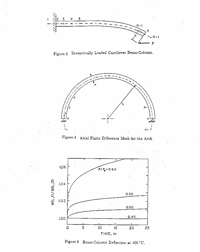
. I c
\- F
Figlire 3 Eccentrically Loaded Cantilever Beam-Column.
t
1.96
1.04
1.0 2
1.00
Axial Finite DiEerexe Mesh for :the Arch
0 5 IO 15 TIME, hr
20 25
Figllre 5 Beam-Column Deiiection at 400 ' C .

1.08
1.06
1.04
1.02
1.00
0
0.50
I 1 I ! J 5 10 15
TIME, h r
20 25
Figure 6 Eeam-Column Deflection ai 600 " C .
- .
4.0
3.0
2.0
1 .o
0 400 800 TIME, sec
Figure 7 Beam-Column Deflection at 800 "C .

-10
- - I I 1 I t
.- . -14 VI 3
- 26
I I -I
0.60
I 1 t I
0 5 10 I5 20
TIME, h r
Figure 8 Dizerence Between Actual Stress and Backstress at 400 ' C .
.- VI 3 - A
(u \ c I
0- -
-4
-8
-12
-16
Figure 9 Dizeerence Berween Xctuai Stress and Backstress at S(

.07 t 1
.05
I I
- 22 -
-.I t- 1 1 1 I 1 I I 20 60 I O 0 I40
TIME, min
Figure 10 Cec:er DefiecTion 1-ersus Time for the 600 " C Low -Arch.
.O 6
.O 5 c .-
.03 5. 15 25
TIME, s e c
. Figure 11 Cexter Defieciion I - e r s c s Time for the 900 ' C Low Xrch.
. .

. .
1 I 1 i
1.015 -
Y
- -
1.000 - I I I I
25 20 0 5 IO 15
T I ME, hr
Figlire 1: Influence of Teslperature DiEerences on a 400 "C Beam-Colux1n.
- I- C 0 0
0 A -
1.8
I .4
1.0
0.6
0.2
I 1 I I 1 I I 1 I - I I
P/P, = 0.50
I I I I I I 1
-10 0 IO 20 -20 TEMPE3 ATURE G R ADlEN T , O C /cm
Figi1x-e 13 Trznne r se De?ection z a Function of Temperature Gradiexi at 600 ' c .

0.17
0.13
200 OC p k - p k - P/P,= 0.50
100 'C p k - p k
I 1 1 1 t 1 1
0 1000 2000 3000 TIME, s e c
Figiire 15 End Deflectioc foi 50 and 100 ' C Xm?lItude Temperature T-ariaTions

P - a. I \
.- v) c
0
W
- X
24
20
16
\
E. A '
0 A S Y
A WALKEF?
- 1 1 1 I I I AI
500 700 900 TEMPEZATURE, "C
Figiire A-.l 1-oung's modulus as a Function oi Temperature
250
. 200
too
50 I 500 700 900
TEMPE2ATURE, 'C

,
-25
i / n
.I5
.O 5
Figiire -4-3
300
"2
200
100
0
I I I I I 500 700 900
TEMPERATURE, "C
n'l as a Function of Temperature
500 70 0 900 TEMPEFIATURE, O C
~ i ~ , ~ ~ ~ -4-4 n 2 zs a Function of Temperature

TEMPERATURE, OC
Figure -4-5 nj as a Fmction of TemperaTure
X
CD c
I 1 I 1 I 1
1 I I I I 1 I 500 700 900
TEMPERATURE, "C . .
Figure -4-6 n6 as a Function of Temperature

0
.- fn a
-800
?i
-1600
I/
Figure -4-7 Reference
500 700 900
TEMPERATURE, "C
Backstress! 0' as a Function of Temperature