analysis, design and implementation of sensorless v/f
TRANSCRIPT

Analysis, design and implementation of sensorless V/f controlin a surface-mounted PMSM without damper winding
SOURABH PAITANDI* and MAINAK SENGUPTA
Department of Electrical Engineering, Indian Institute of Engineering Science and Technology,
Shibpur, Howrah 711103, India
e-mail: [email protected]; [email protected]; [email protected]
MS received 14 March 2016; revised 26 July 2016; accepted 28 September 2016
Abstract. This paper presents a novel, reliable and efficient V/f control implementation on a 8-pole, 750 rpm,
5 kW surface-mounted permanent magnet synchronous motor (PMSM) without damper winding. In the absence
of a damper winding, open loop V/f control of SM is inherently unstable, particularly at high speeds. Stabili-
sation can be done with proper stator frequency modulation in accordance with the change in rotor speed to
provide for effect of damping. This has been implemented here without use of any shaft-mounted encoder. The
change in rotor speed is observed from power perturbation, thereby eliminating the need for using a speed sensor
in the drive. The efficiency of the drive is further increased with appropriate control of the power factor,
irrespective of load and frequency variations. Simulated and experimental results are presented for both open-
loop and the proposed V/f control. These results establish the accuracy of the design of the proposed V/f control
strategy and the precision of hardware implementation. A comparative study between the proposed V/f control
method and standard vector control method, as implemented on this PMSM, has also been presented here to
establish the advantages of the proposed scheme. The PMSM itself was designed and fabricated in the
laboratory.
Keywords. Surface-mounted PMSM; V/f control; sensorless control; stabilisation of PMSM; efficiency
optimisation.
1. Introduction
Use of permanent magnet synchronous motor (PMSM)-
based drives is increasing in several applications due its
well-known advantages. Different control techniques such
as vector control, direct torque control and V/f control with
or without position/speed sensor are being used in the
PMSM drive [1–3]. Although, both the vector control and
direct torque control techniques yield fast dynamics, the V/f
control is one of the simplest control techniques, where the
speed of the PMSM can be controlled by varying the supply
frequency. Use of V/f control first started for induction
motor (IM) which does not require very fast dynamic
response. Various techniques were reported for improve-
ment of V/f-control-based IM drive performance [4, 5].
However, the open-loop V/f control of wound-field syn-
chronous motor without damper winding is inherently
unstable beyond a certain frequency range [6, 7], which has
been discussed later in this paper. The stabilisation can be
done by providing for the effect of damping torque using an
appropriate control strategy during speed transients of the
rotor [7]. The methods of stabilising a reluctance
synchronous motor using a speed sensor is reported in [8].
An additional speed sensor or position sensor, as used in
most cases, increases the cost and reduces the system
reliability. The use of V/f control for PMSM was first
reported in [9]. Different stabilisation techniques with
proper power factor control technique using DC-link cur-
rent sensing [9], DC-link peak current control [10], rotor
position estimation using stator voltage and current have
also been reported in literature. V/f control can be used for
the line start PMSM with damper winding in rotor [11].
However, due to different design complexities and to have
cost reduction, most of the PMSMs do not have damper
winding [11]. Perera et al [12] suggested a stabilisation
technique using input power perturbation along with a
voltage control method for constant flux linkage operation
and power factor control, but implemented in a IPMSM
with damper windings, which has vastly different electro-
mechanical dynamics (in comparison with surface-mounted
PMSM (spmsm) without damper winding) since in IPMSM
Lq [ Ld . Additionally, in IPMSMs the buried PMs are
mechanically secured against torque and unbalanced mag-
netic pull transient. For stable V/f operation of these
PMSMs, the damping torque is provided by controlling the
torque angle (d) during speed transients. The present paper*For correspondence
1317
Sadhana Vol. 42, No. 8, August 2017, pp. 1317–1333 � Indian Academy of Sciences
DOI 10.1007/s12046-017-0662-4

presents the design and implementation of a novel sensor-
less stabilisation technique with power factor control for
surface-mounted PMSMs. The efficiency of the drive has
been increased by controlling the terminal power factor (’internal power factor, since d is small) of the PMSM by
controlling the reactive power. The power factor control
strategy suggested and implemented in this paper is much
simpler than suggested in [10, 12]. The proposed V/f control
scheme is shown in figure 1.
This paper also presents a comparative study between the
proposed V/f control and the conventional vector-control-
based drive both implemented on this fabricated PMSM.
The vector control scheme has been implemented here with
a shaft-mounted position encoder. A detailed comparison
highlighting the merits and demerits of the proposed drive
has also been presented for ready reference.
The entire PMSM drive has been designed, implemented
and tested on a laboratory prototype surface-mounted PMSM.
The ratings and other important parameters of the system are
given in the ‘‘Appendix’’. Interestingly, even the PMSM itself
has been designed and fabricated by the authors with the help
of a small machine manufacturer using imported magnets
[13, 14]. The PMSM is coupled mechanically to (i) a brake–
pulley arrangement (1 kW) and (ii) a 4 kW, 110 V, 750 rpm
DCseparately excited generator for loading. This combination
of mechanical and electrical loading has been made keeping
quite a few interesting issues in mind. At starting and at low
speeds the generator develops no emf and hence cannot be
used for experimentswhere the goal is to apply significant load
(torque) at low speeds. This is relevant in variable speed in low
speeds zone of variable speed drive tests.Amechanical load of
full capacity (5 kW) on the other hand will lead to excessive
heating of the brake–pulley mechanism and sustained loading
cannot be applied. Additionally, available DC generators of
this above rating could be procured with much difficulty. A
5 kWDCgenerator at 110 V (laboratoryDC supply is 110 V)
could rarely be locatedwith any vendor; if one suchmachine is
to be specially manufactured on a single-piece basis it would
become prohibitively costly as also its size would be much
more than the available space in the test bench. Hence, this
arrangement was made. The control algorithm has been
implemented on an FPGA platform.
2. Modelling of PMSM
For the surface-mounted PMSM used here, Ld ¼ Lq ¼ L
[13, 14]. The PMSM electromechanical model can be
represented by [15]
vd
vq
� �¼ R þ pL �xL
xL R þ pL
� �idiq
� �þ 0
xw0
� �ð1Þ
Jdxr
dt¼ PTe
2� Bxr �
PTL
2ð2Þ
where xr is mechanical speed in elec. rad/s, x is stator fre-
quency in elec. rad/s,w0 is no-load flux linkage,P is number of
poles and p ¼ ddtis the Heaviside operator. All other symbols
have their usual significance. From figure 2, Vq ¼ Vs cos dandVd ¼ �Vs sin d; d being the load angle.We also know that
the electromagnetic torque developed [15] in the motor is
Te ¼P
2Ld � Lq
� �idiq þ w0iq
� �
¼ P
2w0iq as; Ld ¼ Lq
� �:
Hence
Jdxr
dt¼ P
2
� 2
w0iq � Bxr �P
2TL: ð3Þ
For transient analysis of PMSM it is also important to
consider the load angle. Figure 3 shows the torque angle dduring steady and transient states. From figure 3
Dh ¼ xDt � Dd:
Now, if, Dt ! 0, then DhDt
¼ xr. Hence
xr ¼ x� dddt
: ð4Þ
The state space model of the PMSM can be obtained by
rearranging (1)–(4). However, these equations contain non-
linear terms. Therefore it is necessary to linearise the
equations about some nominal operating point. The non-
linear model can be linearised by assuming [12] that
xi ¼ Xi þ Dxi
where xi is the variable, Xi is the steady state value and Dxi
is a perturbation. Thus linearising (1)–(4), the state equa-
tions of the V/f-controlled drive, we get (5)Figure 1. Block diagram of the proposed V/f controller with
stabilisation and power factor control.
1318 Sourabh Paitandi and Mainak Sengupta

px ¼ Ax þ Bu ð5Þ
where
x ¼ Did Diq Dxr Dd½ �:x ¼ Did Diq Dxr Dd½ �T ;u ¼ Dvs Dx DTl½ �T ;
A ¼
�R=L xr0 Iq �Vs cos d0L
�xr0 �R=L w0=L �Vs sin d0L
0 P=2ð Þ2w0
J�B=J 0
0 0 �1 0
2666666664
3777777775;
B ¼
� sin d0L
0 0
cos d0L
0 0
0 0 �P=2J
0 1 0
26666664
37777775:
The stability analysis can be verified by the eigenvalues of
matrix j A j. For steady-state operation at the nominal oper-
ating point,Dvs ¼ 0 andDx ¼ 0. For simplicity, it is assumed
that motor runs under no load (mechanical losses only), which
implies Iq ’ 0. Table 1 shows the eigenvalues of matrix j A jat different values ofxr0 (nominal stator frequency). It can be
seen from table 1 that the eigenvalues k3 and k4 have positivereal parts for a stator frequency = 230 rad/s (35 Hz) or above,
which proves the presence of instability in the open-loop V/f
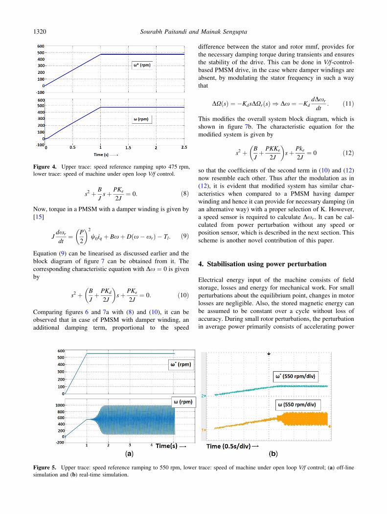
drive. Figure 4 shows machine speed when the speed refer-
ence ramps from 0 to 475 rpm (ramping time is 1 s) under
open-loop V/f control. It can be seen that the machine is
stable at this speed. Figure 5 clearly shows that the machine
becomes unstable when the speed reference is changed to
550 rpm under open-loop V/f control. The PMSM becomes
unstable after the speed reference reaches steady value of
57 rad/s (550 rpm). The same has also been verified by per-
forming real-time simulation of open-loop V/f control of
PMSM (figure 5b) at identical conditions.
3. Simplified analysis and stabilisation of V/fcontrol drive
The state space model described earlier is for open-loop
systems. However, the electrical time constant is much
lesser than the mechanical time constant. Thus we can
simplify (5) to (6) as follows;
pDxr
Dd
� �¼ � J
B0
1 0
� �Dxr
Dd
� �þ 0 P
2J
1 0
� �DxDTl
� �:
ð6Þ
For a small Dd ¼ d1, sin d1 �! d1. Thus, restoring torque
DTe is given by
DTe ¼ KeDd: ð7Þ
The capital letters inserted in the block diagram stand, as
per established convention, as the Laplace domain coun-
terpart of the time domain. The block diagram of the system
described in (6) is shown in figure 6. For constant-fre-
quency operation, under steady-state condition, Dx ¼ 0.
Hence, the characteristic equation of the system in figure 6
is given by
Figure 2. Phasor diagram of PMSM.
Figure 3. Power angle change of PMSM during transients.
Table 1. Eigenvalues of system matrix under open-loop V/f
control at different stator frequencies.
Sl.
no.
x(rad/
s) k1 k2 k3 k4
1 105 -61?j327 -61-j327 -48?j99 -48-j99
2 220 -107?j324 -107-j324 -2.2?j233 -2.2-j233
3 230 -112?j328 -112-j328 3.4?j240 3.4-j240
4 314 -130?j378 -130-j378 21?j269 21-j269
Analysis, design and implementation of sensorless V/f 1319
s2 þ B
Js þ PKe
2J¼ 0: ð8Þ
Now, torque in a PMSM with a damper winding is given by
[15]
Jdxr
dt¼ P
2
� 2
w0iq þ Bxþ D x� xrð Þ � Tl: ð9Þ
Equation (9) can be linearised as discussed earlier and the
block diagram of figure 7 can be obtained from it. The
corresponding characteristic equation with Dx ¼ 0 is given
by
s2 þ B
Jþ PKd
2J
� s þ PKe
2J¼ 0: ð10Þ
Comparing figures 6 and 7a with (8) and (10), it can be
observed that in case of PMSM with damper winding, an
additional damping term, proportional to the speed
difference between the stator and rotor mmf, provides for
the necessary damping torque during transients and ensures
the stability of the drive. This can be done in V/f-control-
based PMSM drive, in the case where damper windings are
absent, by modulating the stator frequency in such a way
that
DXðsÞ ¼ �KdsDXrðsÞ ) Dx ¼ �Kd
dDxr
dt: ð11Þ
This modifies the overall system block diagram, which is
shown in figure 7b. The characteristic equation for the
modified system is given by
s2 þ B
Jþ PKKe
2J
� s þ Pke
2J¼ 0 ð12Þ
so that the coefficients of the second term in (10) and (12)
now resemble each other. Thus after the modulation as in
(12), it is evident that modified system has similar char-
acteristics when compared to a PMSM having damper
winding and hence it can provide for necessary damping (in
an alternative way) with a proper selection of K. However,
a speed sensor is required to calculate Dxr. It can be cal-
culated from power perturbation without any speed or
position sensor, which is described in the next section. This
scheme is another novel contribution of this paper.
4. Stabilisation using power perturbation
Electrical energy input of the machine consists of field
storage, losses and energy for mechanical work. For small
perturbations about the equilibrium point, changes in motor
losses are negligible. Also, the stored magnetic energy can
be assumed to be constant over a cycle without loss of
accuracy. During small rotor perturbations, the perturbation
in average power primarily consists of accelerating power
Figure 4. Upper trace: speed reference ramping upto 475 rpm,
lower trace: speed of machine under open loop V/f control.
Figure 5. Upper trace: speed reference ramping to 550 rpm, lower trace: speed of machine under open loop V/f control; (a) off-linesimulation and (b) real-time simulation.
1320 Sourabh Paitandi and Mainak Sengupta

and change in load power. The power balance equation can
be written as,
pe ¼ Pe þ Dpe
¼ Losses þ dWfe
dtþ 2
P
� 2
Jdx2
r
dtþ 2
P
� 2
Bx2r
þ 2
PxrDTl: ð13Þ
Neglecting change in losses and stored magnetic field
energy,
Dpe ¼2
P
� 2
2Jx0
dDxr
dtþ 2
PTl0Dxr: ð14Þ
Comparing (11) and (14) it can be observed that �Dpe, can
be used to modulate the frequency reference (Dx):
Dx ¼ �KDpe
¼ K2
P
� 2
2Jx0
d �Dxrð Þdt
þ 2 �Dxrð ÞP
Tl0
� : ð15Þ
This modifies the system in figure 7b into the system of
figure 8. The characteristic equation for the modified sys-
tem is given by
s2 þ sB
2Jþ 4KKexr
P
� þ k2
2JP þ KKeTl0ð Þ ¼ 0: ð16Þ
It is interesting to note that additional damping can be
provided through proper selection of K in Eq. (16).
4.1 Stability verification of the proposed closed-
loop V/f control
In the proposed control scheme, the stator frequency varies
in accordance with active power perturbation. Hence, the
stator frequency x has to be included as a new state vari-
able in the state space description of the system. The
change in active power, Dpe, can be obtained using a high-
pass filter (figure 23). Hence
DPeðsÞ ¼s
s þ 1s
PeðsÞ ð17Þ
where s is the time constant of high-pass filter. Using (15)
and (17)
D _xþ Dxs
¼ �K _pe: ð18Þ
Now, power input to the machine is
pe ¼ vdid þ vqiq: ð19Þ
Assuming that the supply voltage remains constant [15]
(figure 2)
pe ¼ ð�Vs sin dÞid þ ðVs cos dÞiq: ð20Þ
Hence
_pe ¼ Vs � _id sin dþ _iq cos d� is cos dþ iq sin d� �
_d �
:
ð21Þ
Replacing for _id; _iq; _d (using (5)) in (18) we get
D _x ¼ KVs xr cos d�R
Lsin dþ x� xrð Þ cos d
� id
þ KVs xr sin d�R
Lcos dþ x� xrð Þ sin d
� iq
þ KVs
w0 cos dL
xr þKVs
L� Dx
s:
ð22Þ
Equation (22) represents the fifth state equation. Lineari-
sation of this gives the new system for stability analysis. It
can be observed from (22) and (12) that the stability of the
Figure 6. Block diagram of the simplified small signal mechan-
ical model of PMSM without damper winding under V/f control.
Figure 7. Block diagram of simplified small-signal model of mechanical dynamics under V/f control: (a) PMSM with damper winding
and (b) PMSM without damper winding with controlled frequency modulation.
Analysis, design and implementation of sensorless V/f 1321

system depends upon value of K and the cut-off frequency
ð1=sÞ of the high-pass filter. It has been found from table 2
that for K ¼ 0:02; k1 and k2 (sl. no. 1, table 2) become
positive and for K ¼ 0:001; k3 and k4 (sl. no. 4, table 2)
become positive. The system is unstable when
0:002[K [ 0:015 for any value of s. Here, K ¼ 0:005 is
chosen. The maximum possible cut-off frequency (here,
16 Hz) for proper damping can be obtained from the pole
locations (table 3) at rated speed under full-load condition.
However here the cut-off frequency of the high-pass filter is
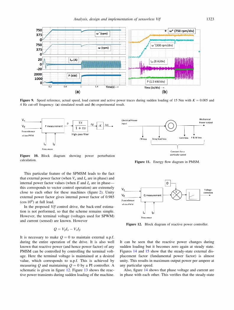
chosen as 3.5 Hz to keep a safe margin. Figure 9 shows the
speed response during starting from 0 speed to 750 rpm and
during sudden loading of the motor at 750 rpm with the cut-
off frequency of 4 Hz (sl. no. 1, table 3). Very low cut-off
frequency makes the settling of speed transients more
sluggish.
It can be observed from figure 9 that during sudden
loading the actual speed falls for a very short transient
period. Simultaneously the frequency reference (i.e. speed
reference) reduces, unlike conventional V/f control, where
the frequency reference is independent of load and speed
variations. This automatic change of supply frequency
during speed transients ensures the stability of the system.
The change in frequency depends on the amount of loading,
gain K and cut-off frequency of HPF. Selection of proper
value of K and cut-off frequency ensures proper frequency
modulation and hence stability of the drive. Finally the
speed comes back to its original value, verifying that there
is very good speed regulation.
4.2 Measurement of power perturbation
Input power in any 3-phase machine can be calculated as
[15] follows:
P ¼ VaIa þ VbIb: ð23Þ
Input power of the PMSM can be calculated using (23)
with the help of reference voltages generated for sine PWM
and sensed phase current for any chosen DC-link voltage of
the inverter. Active power perturbations can be measured
using a high-pass filter using the block schematic shown in
figure 10.
5. Power factor control and efficiency optimisation
For a surface-mounted PMSM, maximum efficiency oper-
ation (g) is achieved when Id ¼ 0. Hence, Ia ¼ Iq. It can be
understood from figure 11 that the maximum efficiency
operation is obtained by minimising the stator copper loss,
since other losses are constant. The PMSM used here (ac-
tually for all the surface mounted PMSM) has very low
inductance (Ld ¼ Lq ¼ 5:5mH; Xpu ¼ 0:14 pu) which
results in a low value of full-load torque angle (here full-
load torque angle dFL ¼ 10�).
Zbase ¼Vbaseðrated phase voltageÞIbaseðrated phase currentÞ
¼ 145
12¼ 12:1X
Xpu ¼ Xactual
Zbase
¼ 314� 5:5� 10�3
12:1¼ 0:14 pu
Figure 8. Block diagram of simplified small-signal model of
PMSM without damper winding with controlled frequency
modulation.
Table 2. Eigenvalues of system matrix under closed loop V/f control at different values of K;x0 ¼ 314 rad/s and s ¼ 0:04 under no
load.
Sl. no. K k1 k2 k3 k4 k5
1 0.02 27?j415 27?j415 -76?j199 -76-1j99 -130
2 0.01 -19?j377 -19-j377 -61?j252 -61-j252 -81
3 0.005 -78?j359 -78-j359 -19?j276 -19-j276 -32
4 0.001 -114?j379 -114-j379 7.74?j261 7.74-j261 -15
Table 3. Eigenvalues of system matrix under closed-loop V/f control at different values of s;x0 ¼ 314 rad/s and K ¼ 0:005 under full
load.
Sl. no. s ðsÞ [f (Hz)] k1 k2 k3 k4 k5
1 0.04 (4) -69?j358 -69-j358 -19?j232 -19-j232 -24
2 0.02 (8) -73?j381 -73-j381 -14?j234 -14-j234 -41
3 0.01 (16) -79?j391 -79-j391 -2.5?j235 -2.5-j235 -56
4 0.005 (32) -85?j396 -85-j396 3?j239 3-j239 -66
1322 Sourabh Paitandi and Mainak Sengupta
This particular feature of the SPMSM leads to the fact
that external power factor (when Va and Ia are in phase) and
internal power factor values (when E and Ia are in phase—
this corresponds to vector control operation) are extremely
close to each other for these machines (figure 2). Unity
external power factor gives internal power factor of 0.985
(cos 100) at full load.
In the proposed V/f control drive, the back-emf estima-
tion is not performed, so that the scheme remains simple.
However, the terminal voltage (voltages used for SPWM)
and current (sensed) are known. However
Q ¼ VbIa � VaIb
It is necessary to make Q ¼ 0 to maintain external u.p.f.
during the entire operation of the drive. It is also well
known that reactive power (and hence power factor) of any
PMSM can be controlled by controlling the terminal volt-
age. Here the terminal voltage is maintained at a desired
value, which corresponds to u.p.f. This is achieved by
measuring Q and maintaining Q ¼ 0 by a PI controller. A
schematic is given in figure 12. Figure 13 shows the reac-
tive power transients during sudden loading of the machine.
It can be seen that the reactive power changes during
sudden loading but it becomes zero again at steady state.
Figures 14 and 15 show that the steady-state external dis-
placement factor (fundamental power factor) is almost
unity. This results in maximum output power per ampere at
any particular speed.
Also, figure 14 shows that phase voltage and current are
in phase with each other. This verifies that the steady-state
Figure 9. Speed reference, actual speed, load current and active power traces during sudden loading of 15 Nm with K ¼ 0:005 and
4 Hz cut-off frequency: (a) simulated result and (b) experimental result.
Figure 10. Block diagram showing power perturbation
calculation.Figure 11. Energy flow diagram in PMSM.
Figure 12. Block diagram of reactive power controller.
Analysis, design and implementation of sensorless V/f 1323

fundamental power factor is unity and the system achieves
zero reactive power operation. Figure 16 provides experi-
mental results showing the dynamic performance at low
speed (150 rpm, 0.2 pu speed). It can be verified from
figure 16a that the PMSM operation remains stable under
this condition also and speed remains constant even after
sudden loading at low speeds also. The reactive power
drawn, as claimed earlier, also becomes zero after the
transient period. Figure 16b shows steady-state operation at
low speed (150 rpm, corresponds to 10 Hz frequency) with
a load of 15 Nm. It can be observed that the external dis-
placement factor is almost unity even at this low speed.
The values of Kp (0.2, here) and Ki (1, here) are chosen
(by iteration) in such a way that it does not affect transient
response of the machine. This is because the control is
being done on stator reference frame without any decou-
pling between d and q-axis. Higher values of Kp and Ki
cause the transient reactive power to get reset to zero faster
but result in speed oscillations during starting of the motor
(figure 17).
It will be worthwhile to mention that this reactive power
controller automatically acts to change the voltage com-
mand even when the DC-link voltage falls/rises from the
chosen DC-link voltage (during loading or due to input
voltage sag, etc.). Thus the reactive power always remains
zero and the fundamental power factor remains unity.
The tests results of V/f control-based-PMSM drive (ma-
chine ratings are given in the ‘‘Appendix’’) at rated speed
with different loads are given in table 4. It can be seen from
results that the efficiency of the drive is very high (close to
efficiency values achievable under vector control operation)
at rated conditions. The torque–speed and power–speed
characteristics for rated current under close-loop V/f control
are shown in figure 18. The torque–speed characteristics
are very similar to that of a separately excited DC machine
(or PMSM under vector control).
It can observed from figure 18 that for constant armature
current of 12 A (rated current) the output power of the
machine increases linearly with speed and gives rated output
power of 5 kW at rated speed of 750 rpm (sl. no. 4, table 4)
and the output shaft torque remains almost constant at 63 Nm
(this is also the rated output torque) up to the rated speed. This
proves that the internal power factor remains very close to
unity, i.e., back emf (E) and phase current (Ia) are almost in
phase for the entire speed range. Figure 18 shows that the
torque remains almost constant for the entire speed range and
the output power increases linearly with speed.
Now the output torque and power are given by
Te ¼P
2w0iq � 3i2ara � core loss � Bx; ð24Þ
P ¼ xP
2w0iq � 3i2ara � core loss � Bx
� : ð25Þ
From (24), constant torque for constant Ia (where, Ia ¼Id þ jIq (figure 2)) proves that Ia ’ Iq and Id ’ 0 at steady
state for the entire speed range. Thus, the speed–torque
characteristics of the proposed control resemble the steady-
state performance of a vector-control-based PMSM drive
where Ia ¼ Iq and Id ¼ 0. A complete photograph of the
test set-up is shown in figure 19.
6. Speed reversal and 2Q operation
The speed reversal and 2Q operation of a 3-phase IM,
running under V/f control, can be done by plugging.
However, for the SPMSM the plugging (sudden inter-
Figure 13. Active power, reactive power and phase during sudden loading of 25 Nm at 750 rpm, (a) simulated result and
(b) experimental result.
1324 Sourabh Paitandi and Mainak Sengupta

change between 2-phases) will make the machine fall out-
of-step. Hence a novel speed reversal technique is used here
for V/f-controlled SPMSM and is shown in figure 20. Here,
the rate limiter changes the speed reference slowly to
reverse polarity. The polarity of frequency modulation used
for stabilisation also has to be reversed for reverse rotation
of the motor. Figure 21 shows the change in speed refer-
ence and frequency reference during speed reversal. Fig-
ure 22 shows the speed reversal of motor from 750 to
-750 rpm with a constant load of 25 Nm.
Figure 22 shows that during sudden speed reversal
command, actual speed reference decreases slowly, then
reverses and finally reaches the reference value. The slope
of the frequency rate limiter is decided from motor inertia.
Actual speed of the machine follows the reference speed,
decreases slowly and finally reverses. It can also be verified
that the magnitude of current remains constant. However,
the frequency of phase current decreases and again
increases as the motor reverses.
7. Starting of the motor
Here the V/f drive is started with the conventional V/f
control method of boosting the voltage command (repre-
sented in the V–f block/curve in figure 1) at low frequency
(from crawling speeds up to 5 Hz, here). This is required
for starting with load, as at low speeds the drop across
stator impedance is not negligible compared with the sup-
ply voltage and constant V/f relation at low speed does not
ensure constant /. It is also observed through off-line and
real-time simulation that the motor can start from any initial
position of the rotor, i.e., initial angular displacement h0(i.e., the angle between d-axis and R-phase axis at t ¼ 0)
Figure 14. (a) Simulated Result: Vph (scale: X-axis, 10 ms/div; Y-axis, 100 V/div) and, Iph (scale: X-axis, 10 ms/div; Y-axis, 12 A/div)
at steady state and (b) experimental result: Vph (scale: X-axis, 5 ms/div; Y-axis, 250 V/div) and Iph (scale: X-axis, 5 ms/div; Y-axis,
20 A/div) at steady state.
Figure 15. (a) Simulated result: Vph�ref and Iph at steady state and (b) experimental result: Vph�ref and Iph at steady state.
Analysis, design and implementation of sensorless V/f 1325

estimation, which involves complex algorithms and lesser
accuracy for SPMSM (i.e., no saliency), is not required for
the proposed V/f control system. This is a major practical
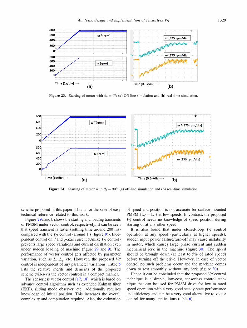
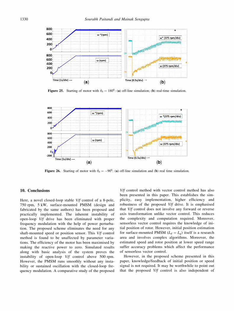
advantage of this proposed scheme. Figures 23–26 show
starting of the PMSM with a load of 10 Nm for various
initial positions. It can be seen in the simulated results that
the motor starts and rotates smoothly in forward direction
for different rotor positions. The same has been experi-
mentally verified also and presented here. This is another
highlight of this paper.
Figure 16. (a) Channel 1: active power (scale 1 kW/div), Channel 2: reactive power (500 VA/div), Channel 3: phase current (5 A/div),
Channel 4: actual speed (150 rpm/div) during sudden loading of 15 Nm; (b) Channel 1: phase voltage (scale 250 V/div Channel 2: phase
current (5 A/div), Channel 3: actual speed (75 rpm/div).
Figure 17. Voltage command (V�) (scale: X-axis: 50 ms/div, Y-axis: 50 V/div) and x (scale: X-axis: 50 ms/div, Y-axis: 50 elec. rad/s)
(a) for Kp ¼ 0:2;Ki ¼ 1 and (b) for, Kp ¼ 0:4;Ki ¼ 2.
Table 4. Test results of a 5 kW PMSM under closed-loop V/f
control.
Sl.
no. VLLðVÞ IphðAÞSpeed
(rpm)
Output
power
(W)
Load
(%)
Efficiency
(%)
1 264 0.6 750 100 2 36.8
2 268 2.1 750 690 14 71
3 273 6.7 749 2815 57 89
4 278 12 748 5135 102 92
1326 Sourabh Paitandi and Mainak Sengupta

Particularly, we can observe in figures 23– 26 that the
actual torque angle during starting depends on the initial
position of rotor (d-axis) with respect to R-phase axis.
Hence, the torque produced during starting varies for dif-
ferent initial positions. Depending on the initial position the
starting torque may be positive or negative. However, as the
frequency increases slowly (depends on the slope on rate
limiter of frequency command) and hence the rotating
magnetic field produced by the stator current slowly
develops speed, the rotor gets locked with the rotating
magnetic field and starts to rotate in forward direction.
8. Vector control implementation
The control technique for vector-control-based PMSM
drive is well established [2, 3] and has been implemented in
this PMSM also. The basic block diagram [16] of con-
ventional vector-control-based PMSM drive is shown in
figure 27. It is being briefly discussed here. Vector control
involves unit vector generation with rotor angle feedback
from the position encoder, forward and reverse reference
frame transformations, implementation of PI controller for
speed and current control. Continuous feedback of the
stator currents and rotor position is therefore required for
vector control operation. All these point towards the need
for a high-end digital controller (here FPGA). As the unit
vectors are generated from machine position and speed,
vector control always maintains synchronism even under
transient load and speed variation.
The vector control is implemented on rotor reference
frame (unlike the V/f control, which is implemented in
stator reference frame). The primitive machine model of the
PMSM (without any damper winding) may be developed
following [15] and is given by
vd ¼ Rid þ Ld
did
dt� weLqiq; ð26Þ
vq ¼ Riq þ Lq
diq
dtþ weLdid: ð27Þ
Torque produced by the PMSM can be written as [15]
follows:
Te ¼P
2wdiq � wqid
� �
where wd ¼ Ldid þ w0 and wq ¼ Lqiq. The mechanical
dynamics can be described by
Jdwm
dt¼ Te � TL � Bwm:
All the notations carry their usual meanings [15].
Vector control of PMSM involves the following steps:
1. Speed need to be sensed and it should remain constant at
the set reference irrespective of load variation. This
implies control of developed torque, which means that iq
needs to be controlled.
2. id is usually set to zero.
Figure 18. Torque–speed and power–speed characteristics of
PMSM under close loop V/f control at a constant current of 12 A.
Figure 19. Photograph of the complete test set-up of the PMSM
with loading arrangements and the converter.
Figure 20. Block diagram of the proposed closed loop V/f control
of PMSM with 2Q operation.
Analysis, design and implementation of sensorless V/f 1327

3. Armature currents need to be sensed.
4. Coupling exists between d � q axis voltages. This needs
to be decoupled.
5. Stator voltage in d � q reference frame has to be
transformed to stationary reference frame.
6. PWM algorithm has to be executed to generate gating
signals.
From (26) and (27), it is seen that the d and q-axis
voltages are coupled. However, for independent control of
d and q-axis quantities, it is necessary to decouple the d and
q-axis voltages.
The same is accomplished following established methods
[2]. The development is repeated here for the sake of ready
reference. The output of the d-axis current controller (fig-
ure 28) leads to the relation
vsd0 ¼ Risd þ L
disd
dt:
Hence, the response of the d-axis current controller is
decoupled from the effect of q-axis current.
vsd ¼ v0sd � weLisq:
Similarly, the q-axis current controller output leads to the
relation
v0sq ¼ Risq þ Ldisq
dt:
Hence
vsq ¼ v0sq þ weLisq þ wew0:
The detailed control procedure is shown in the block dia-
gram in figure 27.
9. Comparison of proposed V/f control with vectorcontrol
As mentioned earlier the popular vector control scheme was
implemented in this machine to set up a solid basis for
establishing the merits and demerits of the novel
Figure 21. (a) Speed reference, (b) frequency reference after rate limiter, (c) actual speed, (d) theta generated from frequency
reference, and (e) omega perturbation during speed reversal of 750 to -750 rpm.
Figure 22. Speed reference, actual speed and phase current during speed reversal from 750 to -750 rpm: (a) off-line simulation and
(b) experimental result.
1328 Sourabh Paitandi and Mainak Sengupta
scheme proposed in this paper. This is for the sake of easy
technical reference related to this work.
Figure 29a and b shows the starting and loading transients
of PMSM under vector control, respectively. It can be seen
that speed transient is faster (settling time around 200 ms)
compared with the V/f control (around 1 s (figure 9)). Inde-
pendent control on d and q-axis current (Unlike V/f control)
prevents large speed variations and current oscillation even
under sudden loading of machine (figure 29 and 9). The
performance of vector control gets affected by parameter
variation, such as Ld; Lq, etc. However, the proposed V/f
control is independent of any parameter variations. Table 5
lists the relative merits and demerits of the proposed
scheme (vis-a-vis the vector control) in a compact manner.
The sensorless vector control [17, 18], which is based on
advance control algorithm such as extended Kalman filter
(EKF), sliding mode observer, etc., additionally requires
knowledge of initial position. This increases the overall
complexity and computation required. Also, the estimation
of speed and position is not accurate for surface-mounted
PMSM ðLd ¼ LdÞ at low speeds. In contrast, the proposed
V/f control needs no knowledge of speed position during
starting or at any other speed.
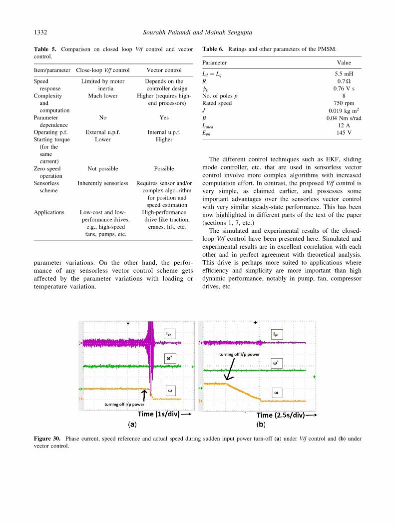
It is also found that under closed-loop V/f control
operation at any speed (particularly at higher speeds),
sudden input power failure/turn-off may cause instability
in motor, which causes large phase current and sudden
mechanical jerk in the machine (figure 30). The speed
should be brought down (at least to 5% of rated speed)
before turning off the drive. However, in case of vector
control no such problems occur and the machine comes
down to rest smoothly without any jerk (figure 30).
Hence it can be concluded that the proposed V/f control
technique is a simple, low-cost, sensorless control tech-
nique that can be used for PMSM drive for low to rated
speed operation with a very good steady-state performance
and efficiency and can be a very good alternative to vector
control for many applications (table 6).
Figure 24. Starting of motor with h0 ¼ 900: (a) off-line simulation and (b) real-time simulation.
Figure 23. Starting of motor with h0 ¼ 00: (a) Off-line simulation and (b) real-time simulation.
Analysis, design and implementation of sensorless V/f 1329
10. Conclusions
Here, a novel closed-loop stable V/f control of a 8-pole,
750 rpm, 5 kW, surface-mounted PMSM (design and
fabricated by the same authors) has been proposed and
practically implemented. The inherent instability of
open-loop V/f drive has been eliminated with proper
frequency modulation with the help of power perturba-
tion. The proposed scheme eliminates the need for any
shaft-mounted speed or position sensor. This V/f control
method is found to be unaffected by parameter varia-
tions. The efficiency of the motor has been maximised by
making the reactive power to zero. Simulated results
along with basic analysis of the system proves the
instability of open-loop V/f control above 500 rpm.
However, the PMSM runs smoothly without any insta-
bility or sustained oscillation with the closed-loop fre-
quency modulation. A comparative study of the proposed
V/f control method with vector control method has also
been presented in this paper. This establishes the sim-
plicity, easy implementation, higher efficiency and
robustness of the proposed V/f drive. It is emphasised
that V/f control does not involve any forward or reverse
axis transformation unlike vector control. This reduces
the complexity and computation required. Moreover,
sensorless vector control requires the knowledge of ini-
tial position of rotor. However, initial position estimation
for surface-mounted PMSM (Ld ¼ Lq) itself is a research
area and involves complex algorithms. Moreover, the
estimated speed and rotor position at lower speed range
suffer accuracy problems which affect the performance
of sensorless vector control.
However, in the proposed scheme presented in this
paper, knowledge/feedback of initial position or speed
signal is not required. It may be worthwhile to point out
that the proposed V/f control is also independent of
Figure 25. Starting of motor with h0 ¼ 1800: (a) off-line simulation; (b) real-time simulation.
Figure 26. Starting of motor with h0 ¼ �900: (a) off-line simulation and (b) real time simulation.
1330 Sourabh Paitandi and Mainak Sengupta

Figure 27. Block diagram of vector-control-based PMSM drive.
Figure 28. (a) d-axis current control loop and (b) q-axis current control loop.
Figure 29. Vector control operation: (a) PMSM ramping up from 0 to 750 rpm, id; iq; (b) actual speed, iq; id during sudden loading of
0.8 kW at 750 rpm.
Analysis, design and implementation of sensorless V/f 1331
parameter variations. On the other hand, the perfor-
mance of any sensorless vector control scheme gets
affected by the parameter variations with loading or
temperature variation.
The different control techniques such as EKF, sliding
mode controller, etc. that are used in sensorless vector
control involve more complex algorithms with increased
computation effort. In contrast, the proposed V/f control is
very simple, as claimed earlier, and possesses some
important advantages over the sensorless vector control
with very similar steady-state performance. This has been
now highlighted in different parts of the text of the paper
(sections 1, 7, etc.)
The simulated and experimental results of the closed-
loop V/f control have been presented here. Simulated and
experimental results are in excellent correlation with each
other and in perfect agreement with theoretical analysis.
This drive is perhaps more suited to applications where
efficiency and simplicity are more important than high
dynamic performance, notably in pump, fan, compressor
drives, etc.
Table 5. Comparison on closed loop V/f control and vector
control.
Item/parameter Close-loop V/f control Vector control
Speed
response
Limited by motor
inertia
Depends on the
controller design
Complexity
and
computation
Much lower Higher (requires high-
end processors)
Parameter
dependence
No Yes
Operating p.f. External u.p.f. Internal u.p.f.
Starting torque
(for the
same
current)
Lower Higher
Zero-speed
operation
Not possible Possible
Sensorless
scheme
Inherently sensorless Requires sensor and/or
complex algo–rithm
for position and
speed estimation
Applications Low-cost and low-
performance drives,
e.g., high-speed
fans, pumps, etc.
High-performance
drive like traction,
cranes, lift, etc.
Figure 30. Phase current, speed reference and actual speed during sudden input power turn-off (a) under V/f control and (b) undervector control.
Table 6. Ratings and other parameters of the PMSM.
Parameter Value
Ld ¼ Lq 5.5 mH
R 0:7Xw0 0.76 V s
No. of poles p 8
Rated speed 750 rpm
J 0.019 kg m2
B 0.04 Nm s/rad
Irated 12 A
Eph 145 V
1332 Sourabh Paitandi and Mainak Sengupta

Acknowledgements
The authors would like to express their gratitude for the
generous fund support received from the NaMPET-II
initiative of the DeitY, MCIT, Government of India. The
authors wish to thank GE Motors, Sheoraphully, specially
Mr Kausik Pyne, for the support in prototype fabrication.
The authors also thank Veeral Controls, Gandhinagar, for
fabrication of the converter and the assistance received
from the IIEST authorities and research colleagues at the
Advanced Power Electronics Laboratory, Department of
EE, IIEST, particularly Mr N Dutta.
Appendix
See table 6.
References
[1] Zhong L, Rahman M F, Hu W Y and Lim K W 1997
Analysis of direct torque control in permanent magnet syn-
chronous motor drives. IEEE Trans. Power Electron. 12(3):
528–536
[2] Bae B H, Sul S K, Kwon J H and Byeon J S 2003 Imple-
mentation of sensorless vector control for super-high-speed
PMSM of turbo-compressor. IEEE Trans. Ind. Appl. 39(3):
811–818
[3] Seok J K, Lee J K and Lee D C 2006 Speed-sensorless vector
control for permanent-magnet synchronous motors based on
instantaneous reactive power in the wide-speed region. IEEE
Trans. Ind. Electron. 53(2): 399–405
[4] Fallside F and Wortley A T 1969 Steady-state oscillation and
stabilisation of variable-frequency invertor fed induction
motor drives. Proc. IEEE 116(6): 991–999
[5] Koga K, Ueda R and Sonoda T 1990 Constitution of V/f
control for reducing the steady state speed error to zero in
induction motor drive system. In: Proceeding of the IEE IAS
Annual meeting, vol. 1, pp. 639–646
[6] Cornell E P and Novotny D W 1972 Theoretical and
experimental analysis of operating point stability of syn-
chronous machines. IEEE Trans. Power Apparatus Syst.
PAS-91(1): 241–248
[7] Verghese G C, Lang J H and Casey L F 1986 Analysis of
instability in electric machines. IEEE Trans. Ind. Appl. IA-
22: 853–864
[8] Lipo T A and Krause P C 1967 Stability analysis for variable
frequency operation of synchronous machines. IEEE Trans.
Power Appl. Syst. 3: 227–234
[9] Colby Roy S and Novotny Donald W 1988 An efficiency-
optimizing permanent-magnet synchronous motor drive.
IEEE Trans. Ind. Appl. 24: 104–112
[10] Kiuchi M, Ohnishi T, Hagiwara H and Yasuda Y 2010 V/f
control of permanent magnet synchronous motors suit-
able for home appliances by DC-link peak current control
method. In: Proceedings of the International Power Elec-
tronics Conference, pp. 567–573
[11] Bose B K 1997 Power electronics and variable frequency
drives. Technology and applications. New York: IEEE Press
[12] Chandana Perera P D, Blaabjerg F, Pedersen J K and Tho-
gersen P 2003 A sensorless, stable V/f control method for
permanent-magnet synchronous motor drives. IEEE Trans.
Ind. Appl. 39: 783–791
[13] Paitandi S and Sengupta M 2014 Design, fabrication and
parameter evaluation of a surface mounted permanent mag-
net synchronous motor. In: Proceeding of the IEEE Inter-
national Conference on Power Electronics, Drives and
Energy Systems (PEDES)
[14] Paitandi S and Sengupta M 2013 Design, analysis of a sur-
face mounted permanent magnet synchronous motor and its
comparison with an Induction motor of same nominal rating.
In: Proceedings of the National Power Electronics confer-
ence (NPEC)
[15] O’Kelly D and Simmons S 1968 Generalized electrical
machine theory. London: Mcgraw Hill
[16] Ranganathan V T 2006 Lecture notes on electrical drives.
Bangalore, India: IISc
[17] Quan L, Wang Z and Liu X 2014 Sensorless control of
SPMSM using complex number model based position esti-
mation and EKF. In: Proceedings of the 26th Chinese Con-
trol and Decision Conference (2014 CCDC), pp. 2663–2668
[18] Yaojing F, Kai Y and Thogersen P 2010 Research of sen-
sorless control for permanent magnet synchronous motor
systems. In: Proceedings of the International Conference on
Electrical Machines and Systems (ICEMS), pp. 1282–1286
Analysis, design and implementation of sensorless V/f 1333