analysis and optimization ofprismatic and axisymmetric ...978-0-85729-424-1/1.pdf · of prismatic...
TRANSCRIPT

Analysis and Optimization of Prismatic andAxisymmetric Shell Structures

Springer- J1?rlag London Ltd. http://www.springer.de/engine/

Ernest Hinton, Johann Sienz and Mustafa Özak~a
Analysis and Optimization of Prismatic and Axisymmetric Shell Structures Theory, Praetiee and Software
With 247 Figures
, Springer

Ernest Hinton, BSc, MSc, PhD, SDc, CEng, MIStructE, MBCS Late ofUniversity of Wales Swansea, Department of Civil Engineering, Singleton Park, Swansea SA2 8PP, UK
Johann Sienz, BEng, DipI-Ing (FH), MSc, PhD, Dr-Phil (GB), CEng, MIMeehE, CMath,MIMA
University ofWales Swansea, Department of Mechanical Engineering, Singleton Park, Swansea SA2 8PP, UK
Mustafa Özak«;:a, BSc, MSc, phD University of Gaziantep, Department of Civil Engineering, Faculty of Engineering, 27310 Gaziantep, Turkey
British Library Cataloguing in Publication Data Analysis and optimization of prismatic and axisymmetric
shell structures : theory, practice and software 1. Shells (Engineering) - Computer simulation I. Hinton, E. (Ernest) 624.1'7762'0285
ISBN 978-1-4471-1059-0
Library of Congress Cataloging-in-Publication Data Analysis and optimization of prismatic and axisymmetric shell structures : theory,
practice and software lErnest Hinton ... let al.l. p. cm.
Inc1udes bibliographical references. ISBN 978-1-4471-1059-0 ISBN 978-0-85729-424-1 (eBook) DOI 10.1007/978-0-85729-424-1 1. Shells (Engineering) 2. Structural analysis (Engineering) I. Hinton, E. (Ernest)
TA660.S5 A485 2001 624.1'7762-dc21 2001020291
Apart from any fair dealing for the purposes of research or private study, or criticism or review, as permitted under the Copyright, Designs and Patents Act 1988, this publication may only be reproduced, stored or transmitted, in any form or by any means, with the prior permission in writing of the publishers, or in the case of reprographie reproduction in accordance with the terms of licences issued by the Copyright Licensing Agency. Enquiries concerning reproduction outside those terms should be sent to the publishers.
ISBN 978-1-4471-1059-0
http://www.springer.co.uk
© Springer-Verlag London 2003 Originally published by Springer-Verlag London Limited in 2003 Softcover reprint ofthe hardcover 1st edition 2003 The software disk accompanying this book and all material contained on it is supplied without any warranty of any kind.
The use of registered names, trademarks etc. in this publication does not imply, even in the absence of a specific statement, that such names are exempt from the relevant laws and regulations and therefore free for general use.
The publisher makes no representation, express or implied, with regard to the accuracy of the information contained in this book and cannot accept any legal responsibility or liability for any errors or omissions that may be made.
Typesetting: Camera ready by the authors 69/3830-543210 Printed on acid-free paper SPIN 10762874
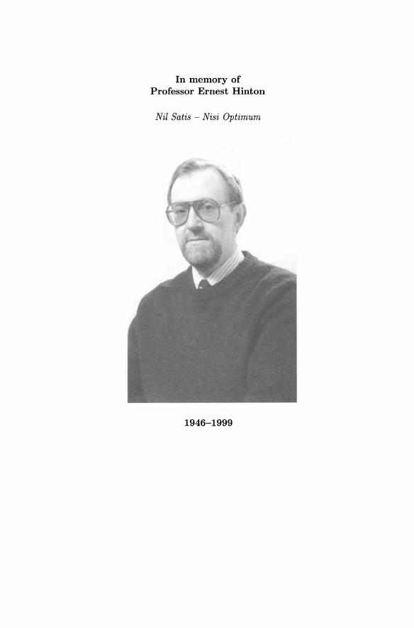
In memory ofProfessor Ernest Hinton
Nil Satis - Nisi Optimum
1946-1999
Preface
Background - During 1989 we, Dr Mustafa Ozakca (MO) and Dr Johann Sienz(JS), arrived here in Swansea to do postgraduate studies in the field of finiteelements (FEs) anslysis in the Department of Civil Engineering jointly withother students. Professor Ernest Hinton , or Ernie as people called him, whohad already published numerous papers and several outstanding books, hadjust been awarded a Personal Chair . Under the supervision of Ernie we startedto work on various aspects of adaptivity and optimization. This led to the successful completion of MO's and JS 's PhDs and numerous publications. The innovative combination of adaptive FE analysis and shape optimization was theinitial thrust of the research . This led to the initiation of the ADOPT researchgroup led by Professor Hinton. Since then, six more students have completedtheir PhDs from the ADOPT group , many more publications have been produced and the group has continuously attracted funding . Ernie adopted themaxim Nil Satis - Nisi Optimum (nothing is satisfactory unless it is the best)for the ADOPT group from Everton FC, of which he was a keen supporter.This phrase is very apt for optimization, but it applies equally to the spirit inwhich he did all his work.
In 1996 Ernie started to plot a series of books publishing the work of theADOPT group, and in 1999 he began to work on this book, the second in theseries. Sadly, he died prematurely at the age of 53 in November 1999. Thisbook is dedicated to Ernie. He was a very important member of the pioneering team at Swansea that made it the home of Computational Mechanics inEurope and the world. His personal contribution to this success at Swanseawas considerable. His early textbooks are essential reading material for students around the world and became benchmarks for later treatises on FEs . Hislegacy will always be remembered by future generations of researchers , and bythe many present students who have benefited from his research work. Thethree co-authors of this book benefited from Ernie's seemingly infinite motivation and inspiration during our PhDs with him and later on as his co-workers.Ernie was an academic, a researcher , and a highly respected and well-lovedindividual, who can best be described as "a scholar and a gentleman havingquality and integrity" .
People who knew Ernie will recognize his hallmark on the book, and theaddition of certain material reflects his personal interests. Ernie was fond ofmusic in general, and part of his work was to look at a variety of instrumentsfrom an acoustic point of view. So it is not surprising that the book containsas one of its Appendices "Musical Scales and Temperament"and some of theoptimization examples deal with the tuning of church bells. Other instrumentslooked at by Ernie are harps - one of Wales' national instruments - and steeldrums as musical instruments, which originated in Trinidad in the pre-WorldWar II period. Steelpan instruments are typically made from 55 gallon drums,
VB

viii Preface
in which musical notes are founded within one of its end surfaces sunk to anapproximately ellipsoidal concave bowl. The cylindrical section of the drum isthen cut to a length thought to be commensurate with the frequency rangeof its notes. The instrument is played with a rubber-tipped mallet (stick) andmay be characterized as an idiophone in the broader category of percussioninstruments. Steelpan instrument types are typically manufactured to mirrorthe frequency range of instruments of the conventional orchestra.
This book follows the long tradition of Ernie's work, in that it combinestheory, applications and software. It is completely self-contained and providesthe reader with source codes backing up the theory developed in the main partof the book, a compiler and a visualization tool.
Objectives - This book is concerned with the development and application of reliable, creative and efficient computational tools for the analysisand structural optimization of variable-thickness shells and folded plate structures. Structural optimization procedures involve the efficient integration ofcomputer-aided curve and surface modelling tools, automatic mesh generation, structural analysis, sensitivity analysis and mathematical programmingmethods.
Layout - The book is divided into five parts:
• Part I: Introduction
• Part II: Static Analysis and Optimization
• Part III : Free-vibration Analysis and Optimization
• Part IV: Dynamic and Buckling Analysis and Optimization
• Part V: CD-ROM
The first part contains the introduction, followed by procedures used todefine the structural shape and for automatic mesh generation. The geometricmodelling is based on cubic splines, these allow for flexible shape generationand control, making it ideally suited for optimization. The loading, boundaryconditions and optimization parameters are all associated with this model.Thereafter comes an outline of the basic algorithm of structural shape optimization. Different approaches to solving the optimization problem are brieflydescribed. The computation of the sensitivities necessary for gradient-basedoptimization is then derived. The sensitivities give a good insight into thestructural behaviour and its response to changes in the design.
The second part of the book deals with the static analysis and shape optimization of shells of revolution and prismatic shell structures, which areidealized as effectively one-dimensional problems. The basic formulations ofcurved, variable thickness, Mindlin-Reissner FEs and finite strips are presented for shells of revolution and prismatic shells respectively. The accuracy

Preface ix
of the elements and strips is verified using several benchmark tests. The basicalgorithm of structural shape optimization is then applied to several examples.
The third part of the book deals with free-vibration analysis and shapeoptimization of axisymmetric and prismatic shell structures, which are idealized as effectively one-dimensional problems. The theoretical formulations offamilies of curved, variable thickness C(O) Mindlin-Reissner FEs and finitestrips are presented for axisymmetric and prismatic shells respectively. Theaccuracy and convergence properties of the elements and strips are establishedusing several benchmark examples. Then , feasible optimum designs for severalvibrating axisymmetric and prismatic shell examples are obtained.
The fourth part of the book deals with the dynamic and buckling analysisand shape optimization of plates , axisymmetric and solids-of-revolution-typestructures. Some closed-form solutions are given, followed by structures idealized using FE and finite prism formulations . The algorithms are tested usingseveral examples and optimal designs are obtained.
Finally, the implementation of software for optimization of both axisymmetric and prismatic shells undergoing static, free vibration, dynamic or buckling behaviour is presented on the included CD-ROM. The structure of theprograms and the function of each subroutine is discussed extensively. Usermanuals and program instructions are also given in this section. Also includedon the CD-ROM are several programs: SANOPT-S , SANOPT-F, SANOPT-P,TRAM, VISOR, PLATES, SPLINE, PREP and OPTIMIZE. All programs arewritten in Fortran and use the FE/finite strip/finite prism method as the analysis tools. Although every attempt has been made to verify the programs, noresponsibility can be accepted for their performance in practice. Furthermore,the CD contains a Tools section with a Fortran compiler and visualizationsoftware.
Johann SienzMustafa Ozakca
Swansea, 9 April 2003
Acknowledgements
It is our pleasure to thank our many friends and colleagues at the University ofWales Swansea in the School of Engineering, especially all the members of theADOPT Research Group and the Centre for Polymer Processing Simulationand Design, both past and present , for their friendship, support and usefultechnical discussions.
JS would like to thank his colleague Dr JFT Pit tman , and Professor K-UBletzinger , Dr R Jones, Dr OM Querin , Professor GP Steven and ProfessorVV Toropov for useful and st imulati ng communicat ions, and for the ir support.Further thanks go to Dr A Polynkin , SJ Bates, H Ettinger , DS Langley andA Rippl for proof-reading parts of the manuscript .
MO wishes to thank his friend Dr IH Giizelbey and graduate students fortheir support and valuable assistance.
The support of the EPSRC UK funding agency and Association of Commonwealth Scholarship Commission in the UK, as well as the st imulat ing forums provided by ISSMO, ASMO UK and EDO-Net , are also grate fully acknowledged.
Finally, our special thanks go to our families for their encouragement, pat ience and moral support .
Johann SienzMustafa Ozakca
Swansea, 9 April 2003
xi

Contents
Contributors xxiii
Notation xxv
Part I: Introduction
1 Introduction 31.1 Background 41.2 Previous work 5
1.2.1 Structural shape opt imizat ion of shells and foldedplates under static condit ions 5
1.2.2 Vibratin g shells of revolution 61.2.3 Vibrati ng prismatic shells and folded plates 7
1.3 Classificat ion of st ructural optimization problems 71.3.1 Classification based on mode of behaviour 71.3.2 Classification according to type of design variable 8
1.4 Classification of shells 81.4.1 Indian Standard classification of shells and folded
plates 91.4.2 Simplified classification of shells and folded plates 91.4.3 Summary of struct ures considered : . . . . . . . . . 9
1.5 Computer-aided shape definit ion 121.5.1 Shape definition of shells of revolut ion and prismatic
shells 121.6 Element technology 12
1.6.1 Elements for shells of revolution 131.6.2 Strips for prismatic shells 14
1.7 Automatic mesh generation 141.7.1 Automatic mesh generation for shells of revolution
and prismatic shells 151.8 Structural shape opt imizat ion 15
1.8.1 The basic algorithm 171.8.2 Sensitivity analysis 181.8.3 Sensitivi ty analysis of static response 181.8.4 Sensitivi ty analysis of dynamic problems 191.8.5 Selection and linking of design variables 191.8.6 Selection of constraint points 201.8.7 Optimiz ation algorithm 20
1.9 Typical shell problems treat ed 201.10 Software developed in this book 201.11 Layout of the book 22References 24
xiii

XIV Contents
2 Structural Shape Definition and Automatic MeshGeneration 27
with contributions from NVR Rao2.1 General perspective 282.2 Structural shape definition 30
2.2.1 Three equivalent representations of a parametriccubic spline 30
2.2.2 The cubic B-spline representation 352.2.3 Terminology 362.2.4 Computer implementation 372.2.5 Specification of end condition of splines 38
2.3 Structural thickness definition 412.4 Automatic mesh generation 42
2.4.1 General requirements 422.4.2 Algorithm for mesh generation 43
2.5 Shape definition and mesh generation in structural analysis . 452.6 Shap e definition and mesh generation in structural
optimiz ation 482.6.1 Shape design variables 482.6.2 Selection of thickness design variables 492.6.3 Linking of design variables 512.6.4 Perturbation of design variables 542.6.5 Prescribed move directions 56
2.7 Other applications of the present tools 56References 58
3 Structural Optimization Methods and Algorithms 593.1 General perspective 60
3.1.1 Problem classification 613.1.2 Problem definition and formulation 653.1.3 Basic algorithm and three- columns concept 683.1.4 Other important aspects 72
3.2 Optimization algorithms 743.2.1 Overview 743.2.2 Mathematical programming 753.2.3 Genetic algorithms 883.2.4 Approximation concepts 99
3.3 Sensitivity analysis 993.3.1 Overview 993.3.2 Global finite differences 1033.3.3 Semi-analytical method 1073.3.4 Analytical or direct sensitivity method 1123.3.5 Adjoint variable method 1133.3.6 Accuracy assessment 114
Contents xv
3.4 Concluding remarks 116References 117
Part II: Static Analysis and Optimization
4 Basic Finite Element Formulation for Shells ofRevolution 1274.1 General perspective 1284.2 Basic formulat ion 1284.3 Finite element idealization 1304.4 Str ain energy evaluation 1324.5 Benchmark examples 133
4.5.1 Cylindrical tank with non-uniform wall thi ckness 1334.5.2 Clamped circular plate 1344.5.3 Spherical dome under uniform pressure 1354.5.4 Toroidal shell under internal pressure 138
4.6 Closing remarks 138References 140
5 Basic Finite Strip Formulation for Prismatic Shells 141
with contributions from NVR Rao5.1 General perspective 142
5.1.1 Preamble 1425.1.2 Simply support ed Euler- Bernou lli beam 1435.1.3 Simply supported Timoshenko beam 146
5.2 Right prismatic shells 1475.2.1 Basic formulation 1485.2.2 Finite strip idealization 1515.2.3 Branched strips 156
5.3 Benchmark examples 1575.3.1 P lates 1575.3.2 Box-girder bridges 1635.3.3 Cylindrical shells 167
5.4 Prismatic st ructures with curved planform 1715.4.1 Basic formulat ion 1745.4.2 Branched strips 181
5.5 Benchmark examples 1825.5.1 Comparisons with known solut ions for right
st ruct ures analyzed as st ructures with curvedplanform 183
5.5.2 Comparison with known solutions for st ructures withcurved planform 186
5.5.3 New solutions for structures with curved planform 192References 199
XVI Contents
6 Structural Optimization of Shells of Revolution andPrismatic Shells 201with contributions from NVR Rao6.1 General perspective 2026.2 Problem definition 203
6.2.1 Selection of objective function for the problem 2036.2.2 Selection of constraints for the problem 203
6.3 Sensitivity analysis 2056.3.1 Analytical method 2066.3.2 Semi-analytical method 2076.3.3 Stress resultant gradients 2076.3.4 Equivalent stress derivative 2086.3.5 Global finite difference method 2086.3.6 Volume gradient 2096.3.7 Strain energy gradient 209
6.4 Shells of revolution examples 2106.4.1 Clamped circular plate subjected to uniformly
distributed load 2106.4.2 Cylindrical tank under hydrostatic pressure 2146.4.3 Spherical shell under ring load 216
6.5 Right prismatic shells and folded plates examples 2196.5.1 Square plates subjected to uniformly distributed load 2196.5.2 Plates on elastic foundations 2236.5.3 Single-cell right box-girder bridge 2246.5.4 Cylindrical shell roof 2266.5.5 Pinched cylindrical shell 229
6.6 Prismatic shells with curved planform examples 2336.6.1 Plates with curved planform subjected to uniformly
distributed load 2336.6.2 Single-cell curved box-girder bridge 2366.6.3 Pinched cylindrical shell with curved planform 238
6.7 Closing remarks 240References 241
Part III: Free Vibration Analysis and Optimization
7 Basic Finite Element Formulation for VibratingAxisymmetric Shells 2457.1 General perspective 246
7.1.1 Analysis methods 2467.1.2 Applications 246
7.2 Structural analysis and finite element formulation 2477.2.1 Finite element formulation 2487.2.2 Finite element idealization 2517.2.3 Branched elements 255
Contents xvii
7.3 Examples 2567.3.1 Thin circular plate 2567.3.2 Annular plates with linearly varying thickness 2567.3.3 Hemispherical dome 2597.3.4 Conical shell with variable thickness 2607.3.5 Cone-cylinder combination 2637.3.6 Hyperboloidal shell 2657.3.7 Hermetic capsule 2677.3.8 Hermetic can 2697.3.9 Bells 270
References 277
8
9
Basic Finite Strip Formulation for Vibrating PrismaticShells .8.1 Introduction .8.2 Prismatic shells with rectangular planform .
8.2.1 Basic finite strip formulat ion .8.2.2 Finite strip idealization .8.2.3 Branched strips .
8.3 Examples .8.3.1 Square plates .8.3.2 Variable-thickness plates .8.3.3 Stiffened panel .8.3.4 Cylindrical shell .8.3.5 Cylinders with interior partitions .8.3.6 Two-cell right box-girder bridge .
8.4 Prismatic structures with curved planform .8.4.1 Basic finite strip formulation .8.4.2 Finite strip idealization .8.4.3 Branched strips .
8.5 Examples .8.5.1 Annular sector plates .8.5.2 Two-cell box-girder bridge with a curved planform .8.5.3 Right cylinders with interior partitions .8.5.4 Cylinders with interior partitions and curved
planforms .References
Structural Shape Optimization of VibratingAxisymmetric and Prismatic Shells .9.1 General perspective .9.2 Problem definition .
9.2.1 Selection of objective function .9.2.2 Selection of design variables .9.2.3 Selection of constraints .9.2.4 Bounds on design variables .
279
280281281284287288288291299300301304306307310312313313317320
321323
325326327327328328328
XVlll Contents
9.3 Sensitivity analysis 3299.3.1 Derivative evaluat ion 3299.3.2 Analytical method 3309.3.3 Semi-analyti cal method 3319.3.4 Finite difference method 3329.3.5 Derivative of volume 332
9.4 Axisymmetri c shells 3329.5 Axisymmetri c shell examples 333
9.5.1 Circular plates 3339.5.2 Conical shell 3399.5.3 Spherical shells 3439.5.4 Branched shell 3469.5.5 Bells 349
9.6 Prismatic folded plates and shells 3549.7 Pri smat ic folded plates and shells: examples 355
9.7.1 Square plates 3559.7.2 Stiffened panel 3619.7.3 Cylindr ical shell 3639.7.4 Box-girder bridge 365
9.8 Prismatic shells with curved planform : examples 3669.8.1 Annular sector plates 3679.8.2 Cylindrical shell segment with curved planform 3729.8.3 Box-girder bridge 373
References 376
Part IV: Dynamic and Buckling Analysis and Optimization
10 Buckling Analysis and Optimization of Plates and Shells 38110.1 Prismatic plates 38210.2 Strip formulat ion for prismati c plates with rectangular
planform 38310.2.1 Str ain energy 383
10.3 Prismat ic plate examples 38710.3.1 Isotropic plates of uniform th ickness 38710.3.2 Square variable-thickness (Sh/Sh/Sh /Sh) isotropic
plates under uniaxial load 39010.3.3 Stiffened panels under uniaxial load 393
10.4 Axisymmetric plates and shells 39710.5 Finite element formulation for axisymmetric plates and
shells 39710.5.1 Strain energy 398
10.6 Axisymmet ric examples 40310.6.1 Circular plates 40310.6.2 Annular plates 40710.6.3 Thin cylindrical shells 410
10.7 Buckling opt imization of structures 411

Contents xix
10.8 Opt imizat ion examples for prismati c and folded plat es 41210.8.1 Rectangular plate examples 41210.8.2 Stiffened panels 418
10.9 Optimization examples for circular and annular plates 41910.9.1 Circular plates 42010.9.2 Annular plates 423
References 427
11 Basic Dynamic Analysis of Plates, Solids of Revolutionand Finite Prism Type Structures 429
11.1 Analytical models for the dynamic analysis of rectangularsimply supported plates 43011.1.1 Int roduction 43011.1.2 Governing equations 43011.1.3 Closed-form solution: vibration analysis 43411.1.4 Stability analysis 43611.1.5 Dynamic t ransient analysis 43711.1.6 Introduction to examples 44311.1.7 Examples: free vibrations 44311.1.8 Examples: initially st ressed vibrat ion and buckling 44411.1.9 Examples: transient dynamic analysis 446
11.2 Finite element analysis of solids of revolution 45011.2.1 Introduction 45011.2.2 Basic formulation 45211.2.3 Solid of revolution element 45311.2.4 Solid of revolution examples 456
11.3 Finite prism models 46011.3.1 Basic formulation 46011.3.2 The finite prism method 46011.3.3 Example 462
11.4 Related closed-form static analysis of rectangular simplysupported plates 46311.4.1 Introduct ion 46311.4.2 Closed-form solutions 46411.4.3 Fourier series representation of the loads 46511.4.4 Sample solut ions 466
References 472
AppendicesA The Evaluation of certain Str ain Terms 475B Evaluation of the Radius of Curvature R 477C Musical Scales and Temperament 479
Author Index
Subject Index
483
489
xx Contents
Part V: CD-ROM
A CD-Rom Overview and Installation Instructions A-IA.l CD-Rom overview A-2
A.l.l Software packages A-2A.l.2 User manuals A-3A.l.3 Tools and other resources A-3
A.2 Installation instructions of PCs A-4A.3 Internet links A-5
B Documentation and User Instructions of Program"SANOPT-S" B-1B.l Program documentation B-2
B.l.l Overview of the program B-2B.l.2 Block structure and main routines B-2B.l.3 File structures B-7B.l.4 Main dimensions and limitations of the program B-8
B.2 Input instructions B-8B.2.l Main structure of input data B-8B.2.2 User hints B-18
B.3 Specimen input data files B-19B.3.l Cylindrical tank under hydrost atic pressure B-19B.3.2 Single-cell right box-girder bridge B-22B.3.3 Pinched cylindrical shell with curved planform B-25
References B-28
C Documentation and User Instructions of Program"SANOPT-F" . . . . . . . . . . . . . . . . . . . . . . . . . . . . . . . . . . . . . . . . . .. C-lC.l Program documentation C-2
C.l.l Overview of the program C-2C.l.2 Block structure and main routines C-2C.l.3 File structures C-6C.l.4 Main dimensions and limitations of the program C-7
C.2 Input instructions C-7C.2.l Main structure of input data C-7C.2.2 User hints C-16
C.3 Specimen input data files C-17C.3.l Conical shell C-17C.3.2 Square plate C-20C.3.3 Cylindrical shell segment with curved planform C-22
References C-24
D Documentation and User Instructions of Program"SANOPT-P" D-lD.l Program documentation D-2
Contents xxi
D.Ll Overview of the program D-2D.1.2 Block structure and main routines D-2D.1.3 File structures D-3D.1.4 Main dimensions and limitations of the program D-3
D.2 Input instruct ions D-4D.2.1 Main st ructure of input data file for static problems . . D-4D.2.2 Main structure of input data file for free-vibration
and buckling problems D-6D.3 Specimen inpu t data files D-8
D.3.1 Cylindrical shell roof subjected to self-weight loading . D-8D.3.2 Thin circular plate D-10
E Documentation and User Instructions of Program"PREP" E-1
E.1 Program documentation B-2E.1.1 Overview of the program E-2E.1.2 Block st ructure and main routines E-2E.1.3 File structures E-4E.1.4 Main dimensions and limitations of the program B-4
E.2 Input instructions E-4E.2.1 Main structure of input data B-4E.2.2 User hints E-lO
E.3 Specimen input data file E-llE.3.1 Cylinder with hemispherical bottom under internal
pressure E-11
F Documentation and User Instructions of Program"SP LIN E" F-lF.l Program documentation F-2
F.1.1 Overview of the program F-2F.1.2 Block st ructure and main rout ines F-2F.1.3 File st ructures F-3F .1.4 Main dimensions and limitations of the program F-3
F.2 Inpu t instructions F-3F.2.1 Main structure of input data F-3F.2.2 User hint s F-6
F.3 Specimen input dat a file F-6F.3.1 Wheel geomet ry F-6
G Documentation and User Instructions of Program"OPTIMIZE" G-1G.1 Program documentation G-2
G.1.1 Overview of the program G-2G.1.2 Block st ructure and main routines G-2G.1.3 File structures G-3

XXll Contents
G.2 Inpu t instructions G-3G.3 Specimen user-supp lied subrout ines and output data file G-4
G.3.1 Example G-4References G-7
H Documentation and User Instructions of Program"TRAM" H-lH.l Program documentation H-2
H.1.1 Overview of the program H-2H.1.2 Main rout ines H-2
H.2 Input instruct ions H-3H.2.1 The glossary of variable names H-3H.2.2 Main st ructure of input data H-4
H.3 Specimen input data files H-7H.3.1 Free-vibrat ion and buckling analysis of square plate H-7
I Documentation and User Instructions of Program"VISOR" 1-11.1 Program documentat ion 1-2
1.1.1 Overview of the program 1-21.1.2 Main routines 1-2
1.2 Inpu t instructions 1-41.2.1 The glossary of variable names 1-41.2.2 Main structure of input dat a 1-6
1.3 Specimen input data files 1-81.3.1 Simply supported circular plate 1-81.3.1 Simply supported square plate 1-10
References 1-11
J Documentation and User Instructions of Program"PLATES" . . . . . . . . . . . . . . . . . . . . . . . . . . . . . . . . . . . . . . . . . . . . . . J- lJ .1 Program documentation J-2
J .1.1 Overview of the program J-2J.1.2 Main rout ines J-2
J .2 Inpu t instructions J-3J .2.1 The glossary of variable names J-3J.2 .2 Main structure of input dat a J-4
J .3 Specimen input data files J-6J .3.1 Homogeneous isotropic rectangular thin plat es J-6
Contributors
Authors
Ernest HintonADOPT Research GroupSchool of EngineeringUniversity of Wales SwanseaSwansea SA2 8PP, UK
Mustafa Ozak~aCivil EngineeringUniversity of Gaziant ep27310 Gaziant epTurkey
Contributors
NVR RaoCivil EngineeringJawaharlal Nehry Technologcial University KukatpallyHyderabad - 500072A.P., India
Johann SienzADOPT Research GroupSchool of EngineeringUniversity of Wales SwanseaSwansea SA2 8PP, UK
Members of ADOPT ResearchGroupSchool of EngineeringUniversity of Wales Swansea,Swansea SA2 8PP, UK
xxiii

NotationAbbreviations
ADOPTASMO UK
BFGSCCADCAGDDoTEDO-NetEPSRCFFDMFEFIDOFSGAGrGISISSMO
MARS
MMAMRndofSAMSESLPSORs
SQPSSOShID2D3D
ADaptivity and OPTimizationAssociation for Structural and Multidisciplinary Optimization in the UKBroydon, Fletcher, Goldfarb and ShannoClamped edgeComputer-aided designComputer-aided geometric designDesign optimization tools: commercial codeEngineering Design Optimization NetworkEngineering and Physical Sciences Research CouncilFree edgeFinite difference methodFinite elementFully integrated design optimizationFinite stripsGenetic algorithmGeneralized reduced gradientsIndian standardInternational Society of Structural and MultidisciplinaryOptimizationMultipoint approximation method based on response surfacefittingMethod of moving asymptotesMindlin-ReissnerNumber of degrees of freedomSemi-analytical-methodStrain energySequential linear programmingShells of revolution (Chapters 1 - 10), solids of revolution(Chapter 11)Sequential quadratic programmingStructural shape optimizationHard simply supported edgeOne dimensionalTwo dimensionalThree dimensional
xxv

xxvi Notation
Scalars
aij
AAa ll
bBi
c,c.»,0(0), 0(2)ddall
dAd£dr,dzDII e 11
2
Ef( ·)e: gi ,f~if$i,f"'ifCxi' fCyi ' s:F(s)Fo,Fl
Fu,Fv,Fw
Fq"P",9g<1gdgVgWgAgj(S)gu,gv ,9w9q,,91jJ9~,9~,9~
p p94> ,9",
CO,C l
hhk(S)IIeJjJI
coefficient of matrix Aareaallowable arealength of the stripcontrol vertices of B-spline curvecontrol vertices of Bezier curvecosine and sine functionorder of continuitydisplacementallowable displacementinfinitesimal areadifferential arc lengthdifferential of rand z coordinatesflexural rigidityerror energyelastic modulusfunction offorces associated with u, v, and wand harmonic pforces associated with ¢ and 'IjJ and harmonic pforces associated with global rotations and harmonic pobjective functionblending functionsdistributed line forcesdistributed line couplesacceleration due to gravitystress constraintdisplacement constraintvolume constraintfrequency constraintsurface area constraintinequality constraint functiondistributed loadings associated with u, v, and w displacementdistributed line couples associated with rotations ¢ and 'IjJdistributed loadings associated with u, v , and wand harmonicpdistributed line couples associated with ¢ and 'IjJ and harmonicp
blending functionsparametric coordinate or thicknessequality constraint functiontotal potential energytotal potential energy from strip eJacobiandeterminant of the Jacobian matrix
Notation xxvii
kK
r,zr i, Zi, t,rk , Sk, tk
RS(£)i
qx , qy, qzQ(2£Qt ,QtyQt,Q'r/QXI,Qylr(h)
«; kuw , kww£l£cL
elastic foundation modulusbuckling factorstiffness terms related to elastic foundationsarc length coordinateprescribed arc lengthbit length of chromosomespan
mq" m,p distributed couplesM couples applied along a circumferential circle
Mt , M,p radial and circumferential bending momentsMt , My , Mty stress resultants due to bendingM«, M'r/ ' Mt'r/ stress resultants due to bendingMX" Myl, M X'yl bending stress resultants in the local coordinate systemn number of nodesnn number of nodesne number of elementsndv number of design variablesN, shape function associated with node iN axial force applied along a circumferential circle
Nt , N ,p radial and circumferential membrane momentNt , Ny , Nty membrane stress resultantsNt, s ; Nt" membrane stress resultantsNx" Nyl , NX'yl membrane stress resultants in the local coordinate systemp, q harmonicsP point loadPI, P2 key points of parametric cubic spline curvePu i , Pv i , Pwi point loads acting at node i in u, v and w directionPq,i , P,pi point couples acting at node i associated with ¢ and 'l/Jq distributed ring pressure loading
uniform loadslateral force applied along a circumferential circleshear forceshear forcesstress resultants due to shearshear forces in the local coordinate systemfunction of parametric polynomialradial and vertical coordinatetypical coordinates and thicknesses at node inodal Cartesian coordinatesradius of curvatureinverse mesh density functiontypical design variablelower bounds of design variableupper bounds of design variablecoordinates of key point k
xxviii
Sksti,
tkt~~
t(u, V)TU,V,W
Ui, Vi, Wi
Ul, Vi, WiUP, VP, wP
uf, Vf, Wfiii, WiU',V' ,W'
Ue
Ve
VVall
Vinitial
\I W\12II W 11 2
Ilwll~II w II~II w II;II w* 11 2
{II W 11~,}2
{II W 1102
{II w IIn2
wXi , Yi
X,Y,Zx',y',z'X,e ,Y,e ,Z,e
Vectors
ddP
Notation
value of design variable k at iteration number qstress levelling functionthicknessthickness at node ithickness at key point k
thickness associated with key point i and segment jthickness at position U and V on a surface patchtemperatureglobal displacementsnodal degrees of freedom associated with node idisplacement components in £,Y and n directionsdisplacement amplitudes of pth harmonictypical nodal degrees of freedom for node i and harmonic pdisplacements u and W at £ = ldisplacements components in the local directionstrain energy for an elementpotential energy of the applied in-plane stresses for an elementvolume of the structureallowable volume of the structureinitial volume of the structurestrain energystrain energy of the finite element solutionmembrane strain energy of the finite element solutionbending strain energy of the finite element solutionshear strain energy of the finite element solution"exact"strain energy valuemembrane strain energy for harmonic pbending strain energy for harmonic pshear strain energy for harmonic pweight of the structuretypical coordinates of node iglobal Cartesian coordinateslocal Cartesian coordinatespartial derivatives with respect to ~
position vector of control vertices of B-spline curveposition vector of control vertices of Bezier curvedisplacement associated with element e and node ivector of nodal degrees of freedomdisplacement vector at node i and harmonic pvector of nodal degrees of freedom for strip e, harmonic p andnode ivector of unknown displacementsmode shape

m
Pp(h)p'(h)pI! (h)
r(u,v)r(u, v),ur(u, v),vr(u, v),uvr(i,j) ,~
r%rk,sk,tkstit(h)uu',v'Ux' ,y',z'x',y' ,z'
Matrices
B~iEmi , Ebi , Esi
BpiB si
C
Notation xxix
vector of structural loadspseudo-load vectorconsistent nodal force vector associated with node iforce vector associated with node i and harmonic pforce vector at node i and harmonic pvector of distributed loadingsvector of distributed line loadingsvector associated with cubic spline representationfirst derivative vectorposition vectorposition vector at parametric coordinate htangent vector at parametric coordinate hsecond derivative of position vector at parametric coordinatehposition coordinates on a parametric surface patchslope in the u-direction at position (u,v)slope in the v-direction at position (u,v)twist at position (u,v)x-component of the tangent in u-directionx-component of vectorunit vectors in the directions rk , Sk, tkvector of design variablespecified tangent valuesunit tangent vectorsvector of parameter upartial derivatives of vector u, vvector of displacements at £ = ltangent vectorsunit tangential vectors along x', y' and z' axes
membrane strain-displacement matrix for element e and nodeiflexural strain-displacement matrix for element e and node ishear strain-displacement matrix for element e and node imembrane strain-displacement matrix for node i and harmonic pbending strain-displacement matrix for node i and harmonicpshear strain-displacement matrix for node i and harmonic ptransformed strain-displacement matricesin-plane strain displacement matrixshear strain displacement matrixelastic constants matrix

xxx Notation
DDm,Db,Dsn;.»,HHJKij[Kij]pq[Kij]pq
KK~ij
Kt,ij
K~ij
K pij
[K~JPp
MMi j
[M]PP[Mij]pqNNP
t
QR,MT
the matrix of rigiditiesmatrices of membrane, flexural and shear rigiditiesin-plane and transverse elasticity matricesmatrix of parametric coordinate hHessian matrixJacobianstiffness matrix associated with element e and nodes i and jstiffness matrix linking nodes i and j and harmonics p and q
elastic foundation stiffness matrix for nodes i and j and p andqsymmetric, banded stiffness matrixmembrane stiffness matrix for element e and nodes i and j
bending stiffness matrix of element e and nodes i and j
shear stiffness matrix of element e and nodes i and j
in-plane stiffness matrix linking nodes i and jgeometric stiffness matric linking nodes i and j and harmonicpglobal mass matrixmass matrix associated with element e and nodes i and j
global mass matrix associated with harmonic pmass matrix linking nodes i and j and harmonics p and q
shape function matrixshape function matrix associated with node i and harmonicp
matrix of reduced in-plane stiffnesses for plane stressmatrices associated with cubic spline representationtransformation matrix
Greek symbols: scalars
ada(31, (32'Yiy
'Yin, 'Yyn
'Y~(" 'Y1)(,
'Yxz , 'Yyz
angle between x and eaxesdifferential anglenormal rotationsshear straintransverse shear strains in the en and yn planestransverse shear strains in the natural coordinate systemtransverse shear strains in the global Cartesian coordinatesystemassumed transverse shear strains in the natural coordinatesystemmesh densityperturbation of design variable Sk
various errors associated with finite differencesradial strain
E,pEs
El, Eyn n n n
El, Erl' Ex' Ey
ABjj
Bxi, Byi, BziB~i' B~i' e;
7r
IIIIerJtPl0"
0-8
O"all
O"avg
O"cr
O"eq
0"z'a a a a
O"l'O"I)'O"X'O"Y
¢,1j;</Y', 1j;P¢f,1j;f
¢(£)iXlX,pW
Wall
DRdD
Notation xxxi
hoop or circumferential strainradial transverse shear strainstrain in £-direction and longitudinal strainsecond-order strainsLagrange multipliersrotational component for shell of revolutionrotation B at £ = lglobal rotational degrees of freedom at node iglobal rotational degrees of freedom at node i and harmonicprotational degree of freedom at node idifferential of Bshear modification factor taken as 5/6 for isotropic materialscurvature in the £-direction and longitudinal curvaturetwisting curvatureshear modification factorsnondimensional foundation modulusPoisson's ratioisoparametric element natural coordinatedifferential element natural coordinatecurvilinear coordinatesa constantpotential energy functionpotential energy contribution from element eobjective functiondensity of £th finite elementstress componentfinite element shear forceallowable stressaverage stresscritical buckling loadequivalent stressstresses in the z'-directionin-plane stressesrotations of the midsurface normal in the £n and yn planesrotation amplitudes for the pth harmonic termstypical rotational degrees of freedom at node i for harmonicp
spacing functionradial curvaturehoop or circumferential curvaturefundamental frequencyallowable frequencyvolume of element £differential of volume

xxxii Notation
Greek symbols: vectors and matrices
€rn
€b
€rn , €b , € s
e'€'
P
€~€€'
A(J
Ub
Urn
uP
u~, u~, uru'u'pu~T
vector of membrane strainsvector of bending strains or curvaturesmembrane, bending and transverse shear strainslocal strain component vectorvector of in-plane strainsvector of transverse shear strainsassumed transverse shear strain vectorstrain components in the local systemvector of Lagrange multipliersdirection cosine matrixvector of finite element bending momentsvector of finite element membrane forcesstress resultant vector for harmonic pmembrane, bending and shear stress resultant vectorsstress component in the local systemin-plane stressestransverse shear stressesshear stress vector
Special symbols
afE
®2:
partial differential of fbelongs totensor productsummation