analysis and optimization of temperature stratification in ... · analysis and optimization of...
TRANSCRIPT

Analysis and optimization of temperature stratification in a thermal energy storage tank
N. Penkova & N. Harryzanov University of Chemical Technology and Metallurgy, Sofia, Bulgaria
Abstract
A mathematical model of the transient temperature and fluid flow fields in the multiphase domain at a water thermal energy storage tank is composed. The model is applied for an analysis of the transport phenomena at the heat storage accumulator, charged by waste heat flows of a cogeneration unit and discharged by thermal energy supply to the heating installation of a conservatory. Numerical investigations of the transient 3D temperature and fluid flow fields in the accumulator at different charging and discharging regimes have been performed in order to estimate the temperature variations of the outflows, situated at different levels. Recommendations for the improvements of the design and the operation of the accumulator are formulated to ensure higher temperature stratification in the water domain and subsequent continuous and smooth work of the CHP and heating installations. Keywords: thermal energy storage, temperature stratification, CFD, turbulence model, operation.
1 Introduction
Thermal stratified storage tanks are widely used in systems with irregular energy source or existing time lag between energy productions and demands (Beckmann and Gilli [1]). The maintenance of the temperature stratification in liquid media is important for the efficient and correct exploitation of the thermal accumulator. The temperature stratification depends on operating flow rates, heat losses to the environment, mixing due to outlet and inlet streams, configurations of the tank, discharging and charging channels (Khalifa et al. [2]). The temperature fields in liquid accumulating media have been subject of various numerical studies [2–5]. The literature revue of the scientific achievement
Energy and Sustainability V 469
www.witpress.com, ISSN 1743-3541 (on-line) WIT Transactions on Ecology and The Environment, Vol 186, © 2014 WIT Press
doi:10.2495/ESUS140401

in that area indicate that the modeling and numerical simulation of thermal and fluid flow processes in accumulating media is a suitable approach for prediction and optimization of the temperature stratification in the energy storage tanks. Modeling investigations of transient temperature fields in two phase domain with liquid accumulating media have not been reported yet. The aim of the present work is to analyze and improve the thermal stratification in water thermal energy storage tank, charged by waste heat flows of a cogeneration unit and discharged by heat supply to a heating installation of a conservatory. The investigations are performed by numerical analyses of the fluid flow processes in the accumulator media based on a model of transient conjugate heat transfer in multiphase (water and air) domain, separated by free surface.
2 Object of investigation
The investigated accumulator is used to accumulate the waste energy of a cogeneration unit and transfer it to a heating installation of a conservatory (figure 1). The tank has cylindrical form (diameter of 11.3m and height of 10.4m) and is situated on a concrete fundament. The metal walls of the accumulator are insulated with of rock-wool layer with thickness of 0.1m. The water level from the bottom can be controlled. At the moment it is kept at 9 meters according the design recommendations. The pressure in the air space is equal to the atmospheric one.
Figure 1: Thermal accumulator, connected with cogeneration and heating installation.
The accumulator is charged thermally by two hot water flows. The first one exchanges heat with the oil, cooling the gas engine of a cogeneration unit and inflows in the tank with temperature of 85°C at level 8.1m from the bottom. The
470 Energy and Sustainability V
www.witpress.com, ISSN 1743-3541 (on-line) WIT Transactions on Ecology and The Environment, Vol 186, © 2014 WIT Press

second charging flow (6m from the bottom) is heated to 55°C in a heat exchanger for utilization of the thermal energy of the engine exhaust gases and inflows at level 6m from the bottom. The discharge of the accumulator is realized by hot water supply, pumped out from the top layers of the storage tank to the heating installation of the conservatory. All returning flows are loaded in the tank at level l meter. Thermal stratification in the tank is important not only for its efficiency, but also for the smooth work of the installation: the water, cooling the oil is leaded to the heat exchanger from the bottom of the tank and has to be with temperature lower than 62°C. If the heating installation in the conservatory is switched off, the discharge of the accumulator stops and the temperature of the bottom increases. This may break down the work of the cogeneration unit due to violating of the requirements for the temperature of cooling oil water.
3 Modelling and numerical simulation of the thermal and fluid flow fields in the energy storage tank
3.1 Model conception
A system, consisting of momentum, continuity and energy equation, turbulence model, and boundary layer model is solved numerically by ANSYS/CFX for the multiphase domain in the accumulator, covering water and air space, and metal charging and discharging pipes (figure 2).
Figure 2: Geometrical model and finite volumes mesh.
The geometrical model corresponds to the design of the working accumulator for the purpose of model validation. The outlets and inlets in the water space of the object of investigation are with cylindrical form. That is not recommended by the design rules of such type of tanks and leads to low temperature stratification.
Energy and Sustainability V 471
www.witpress.com, ISSN 1743-3541 (on-line) WIT Transactions on Ecology and The Environment, Vol 186, © 2014 WIT Press

All bodies of the geometrical model share common faces to ensure proper finite volume mesh for the conjugate heat transfer between the fluid and metal pipes in the tank. RNG k-ε turbulence model, recommended by Yakhot et al. [6] for modeling of circulation zones is used. Buoyancy calculations are implemented by the Full Buoyancy model [7]. The environmental air density is used for the evaluation of the density difference -ref: ref = 1.2 kg/m3. The properties of water and air are determined by IAPWS correlations and ideal gas law correspondently. The free surface between the air and water space is computer by VOF (Volume of Fluid) algorithm for 3D mesh (figure 3). To ensure an acceptable convergence of the solution the mesh has to be finer near the assumed free surface and near the bottom. To evaluate the temperature stratification and its influence on the function of the accumulator numerical simulations of the thermal and fluid flow fields are implemented at:
steady state at simultaneously thermal charging and discharging; transient process of charging without discharging (switched off heating
installation).
3.2 Initial conditions
Transient process is simulated to compute the temperature and fluid flow fields at simultaneously charging and discharging of the accumulator at the initial conditions:
Vx (x, y, z, 0) = Vy (x, y, z, 0) = Vz (x, y, z, 0) = 0 p = p (x, y, z, 0) = 0 T (x, y, z, 0) = 328 K Volume fractions: y < maintained water level: rwater = 1; rair = 0; y > maintained water level: rwater = 0; rair = 1. The maintained water level in the present case study is y = 9m.
The numerical results at the achieved steady state are used as initial for the subsequent simulation of the transient fields at charging of the accumulator without discharging.
3.3 Boundary conditions
The heat transfer from the fluid domain to the environment is modeled as convection with heat transfer coefficients U, reflecting thermal transmittance at the two-layer wall. The cupola of the tank is accepted as opening boundary to model the keeping of atmospheric pressure in the air space. Mass flows or correspondent velocity components, normal to the boundaries are applied on all inlets and outlets outside the tank. Temperatures of the flows are applied at the inlets only: for the outlets they are computed at the numerical simulations. All pipe ends are “opened” inlets and outlets at the process with simultaneously charging
472 Energy and Sustainability V
www.witpress.com, ISSN 1743-3541 (on-line) WIT Transactions on Ecology and The Environment, Vol 186, © 2014 WIT Press
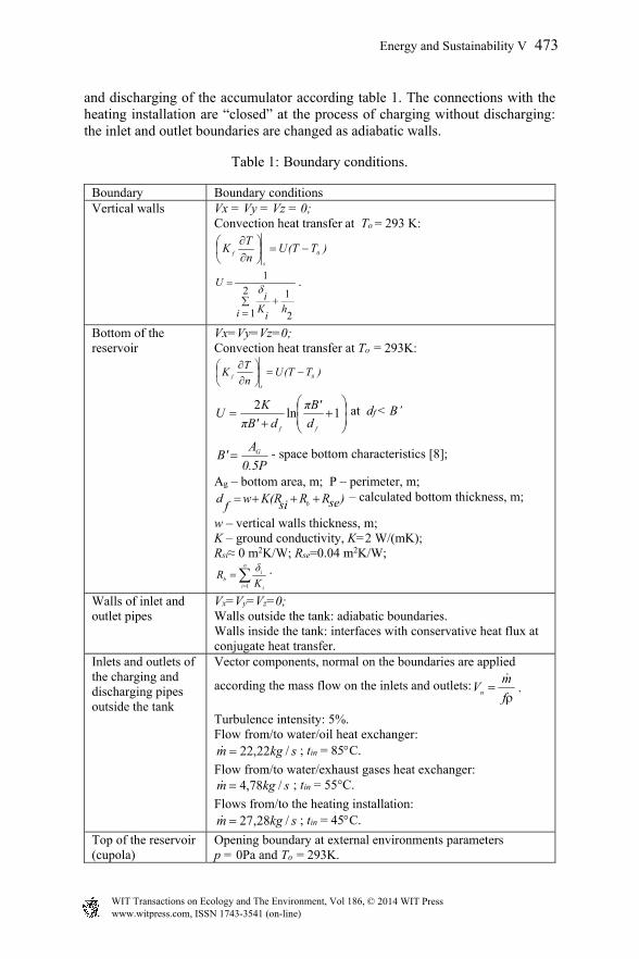
and discharging of the accumulator according table 1. The connections with the heating installation are “closed” at the process of charging without discharging: the inlet and outlet boundaries are changed as adiabatic walls.
Table 1: Boundary conditions.
Boundary Boundary conditions Vertical walls Vx = Vy = Vz = 0;
Convection heat transfer at To = 293 K:
)T(TUn
TK 0
s
f
2
1 2
1
1
i hi
Ki
U
.
Bottom of the reservoir
Vx=Vy=Vz=0; Convection heat transfer at To = 293K:
)T(TUn
TK 0
s
f
1ln
2
ff d
πB'
dπB'
KU at df < B’
0.5P
AB' G - space bottom characteristics [8];
Аg – bottom area, m; P – perimeter, m; )seRRsiK(Rw
fd b – calculated bottom thickness, m;
w – vertical walls thickness, m; K – ground conductivity, K=2 W/(mK); Rsi≈ 0 m2K/W; Rse=0.04 m2K/W;
n
i i
ib K
δR
1
.
Walls of inlet and outlet pipes
Vx=Vy=Vz=0; Walls outside the tank: adiabatic boundaries. Walls inside the tank: interfaces with conservative heat flux at conjugate heat transfer.
Inlets and outlets of the charging and discharging pipes outside the tank
Vector components, normal on the boundaries are applied
according the mass flow on the inlets and outlets:
f
mVn
.
Turbulence intensity: 5%. Flow from/to water/oil heat exchanger:
skgm /22,22 ; tin = 85С.
Flow from/to water/exhaust gases heat exchanger: skgm /78,4 ; tin = 55°С.
Flows from/to the heating installation: skgm /28,27 ; tin = 45С.
Top of the reservoir (cupola)
Opening boundary at external environments parameters р = 0Ра and To = 293K.
Energy and Sustainability V 473
www.witpress.com, ISSN 1743-3541 (on-line) WIT Transactions on Ecology and The Environment, Vol 186, © 2014 WIT Press

4 Temperature and fluid flow fields in the thermal accumulator
4.1 Simultaneously charging and discharging
Numerical simulation of a transient process of charging and discharging of the thermal accumulator varying with the time step from 0.5s initially to 20s finally is implemented. The steady state is established after ½ hour process time. Visualizations of the results are shown figures 3–6.
Figure 3: Water mass fraction and
free surface. Figure 4: Pressure.
Figure 5: Temperature field. Figure 6: Velocity field.
The difference between the temperatures in down and top levels (respectively 1 and 8.1 meter from the bottom) in the water is about 5K. It is not sufficient from the viewpoint of heat supply of the heating installation of the conservatory. The received water temperature at the bottom outflow level is about 50°C that correspond to the measured data at the real object and prove the validity of the used models. The temperatures of the outflows to the heat exchangers at the cogeneration unit are in the permutable boundaries for the smooth work of the installation.
474 Energy and Sustainability V
www.witpress.com, ISSN 1743-3541 (on-line) WIT Transactions on Ecology and The Environment, Vol 186, © 2014 WIT Press

4.2 Charging of the thermal accumulator without discharging
A transient process of thermal charging the storage tank with switched off connections to the heating installation is simulated starting from the received steady state. Increasing of the temperatures at the bottom level near the permutable boundaries for the outflowing flows is established after a process with time duration of 3.20 hours (figure 7). Fluid flow and temperature field at the end of the process are visualized on figures 8–11. The results on the figures above show that the temperatures in water media increase with the time according the expectations. In the same time the temperature difference along the altitude decreases in comparison with the regime of simultaneously charging and discharging of the accumulator. Those small differences are caused by the high velocity of the submerged water jets and respectively high turbulence in the water space causing circulating flows (figure 10).
Figure 7: Temperatures change during the process of thermal charging without discharging of the accumulator.
Figure 8: Temperature field after 3.2 hours charging without discharging. Vertical cross section.
Figure 9: Temperature field after 3.2 hours charging without discharging. Horizontal cross section.
324
326
328
330
332
334
336
338
0 2000 4000 6000 8000 10000 12000 14000
Tem
pera
ture
, K
Time, s
Temperatures at vertical axis of the cylinder
1 meter from the bottom 8.1 meter from the bottom
Energy and Sustainability V 475
www.witpress.com, ISSN 1743-3541 (on-line) WIT Transactions on Ecology and The Environment, Vol 186, © 2014 WIT Press

Figure 10: Streamlines after 3.2 hours charging without discharging.
Figure 11: Turbulent kinetic energy after 3.2 hours charging without discharging.
5 Recommendations for improving the temperature stratification
The numerical results about the transient temperature and fluid flow field in the investigated thermal accumulator show that it can ensure temperature levels of the cooling flows to the heat exchangers at the cogeneration units in a short time (less than 4 hours) in cases of charging without discharging. At the same time the accumulator has a relatively high accumulating potential. The increase of the temperature stratification in the water domain will enable to extend that period, accumulating more thermal energy. The cheaper and easier ways to achieve that purpose at the present construction of the accumulator are: - decreasing of the turbulence in the water space by change of the cylindrical
ends of the charging and discharging pipes with conical diffusors; - rising of the level of the water. That will increase the mass of the
accumulating media and correspondently will reduce the rate of temperature rise in the accumulating media.
The details about the suggestions above can be tested and specified numerically by the presented model conceptions.
6 Conclusions
The presented models and conceptions for numerical simulation enable receiving of detail information for temperature and fluid flow fields in two phase domain in thermal energy storage tanks, connected to small scale power plants and consumers. The modeling investigations can be used for optimization of the accumulator configuration and flow regimes on design or operating level.
476 Energy and Sustainability V
www.witpress.com, ISSN 1743-3541 (on-line) WIT Transactions on Ecology and The Environment, Vol 186, © 2014 WIT Press

Nomenclature
f – surface area, m2 T – temperature, K Vx, Vy, Vz – velocity on x, y, z direction, ms-1 р – pressure, Pa y – water level, m K – conductivity, Wm-1K-1 k – turbulent kinetic energy, Jkg-1 U – thermal transmittance, Wm-2K-1 R – thermal resistance. K m2W -1 m – mass flow, kg/s Greek symbols – density, кgm-3 ε – turbulent kinetic energy dissipation rate, Wkg-1 δ – layer thickness, m Subscripts f – fluid in – inlet si – internal surface se – external surface b – bottom
Acknowledgement
The study was performed with the financial support of Human Resources Development Operational Programme and European Social Fund under project BG051PO0013.3.060014.
References
[1] Beckmann, G. & Gilli, P.V., Thermal energy storage, Springer-Verlag/ Wien, 1984
[2] Khalifa, A. J. N., Mustafa, A.T. & Khammas, F. A., Experimental study of temperature stratification in a thermal storage tank in the static mode for different aspect ratios, ARPN, Journal of Engineering and Applied Sciences, 6(2), pp. 53-60, February 2011
[3] Sameti, M., Kasaeian, A., Mohammadi, S.S., Sharifi, N., Thermal Performance Analysis of a Fully Mixed Solar Storage Tank in a ZEB Hot Water System, Sustainable Energy, 2(2), pp. 52-56, 2014
[4] Altuntop, N., Arslan, M., Ozceyhan, V., Kanoglu, M., Effect of obstacles on thermal stratification in hot water storage tanks, Applied Thermal Engineering, 25, pp. 2285-2298, 2005
Energy and Sustainability V 477
www.witpress.com, ISSN 1743-3541 (on-line) WIT Transactions on Ecology and The Environment, Vol 186, © 2014 WIT Press

[5] Shah, L.J., Furbo, S., Entrance effects in solar storage tanks, Solar Energy, 75(4), pp. 337-348, 2003
[6] Yakhot, V., Orszag, S.A., Thangam, S., Gatski, T.B. & Speziale, C.G., Development of turbulence models for shear flows by a double expansion technique, Physics of Fluids A, Vol. 4, No. 7, pp. 1510-1520, 1992
[7] ANSYS CFX-Solver, Release 12.0: Theory, 2010 [8] BG Code 7/2004: Energy efficiency, thermal accumulation and energy
economy in buildings, 2009
478 Energy and Sustainability V
www.witpress.com, ISSN 1743-3541 (on-line) WIT Transactions on Ecology and The Environment, Vol 186, © 2014 WIT Press