analogue modelling of non-cylindric fold-and-thrust belt
TRANSCRIPT

27
GEOGACETA, 45, 2008
Copyright ® 2008 Sociedad Geológica de España / www.geogaceta.com
Analogue modelling of non-cylindric fold-and-thrust belt arounddiapirs: preliminary results
Modelos analógicos de un cinturón no cilíndrico de pliegues y cabalgamientos alrededor de diapiros: resultadospreliminares
Ana Crespo-Blanc y Eugenio Gálvez
Departamento de Geodinámica, Instituto Andaluz de Ciencias de la Tierra, Facultad de Ciencias, Universidad de Granada, CSIC. Campus Fuentenueva,18071 Granada. [email protected]; [email protected]
RESUMEN
Los modelos analógicos representan una herramienta muy útil para investigar el desarrollo progresivode cinturones de pliegues y cabalgamientos. En este artículo, se presentan resultados preliminares de unaserie de modelos realizados para estudiar el patrón estructural, alrededor de diapiros, de estructurascompresivas desarrolladas sobre un sustrato dúctil. Sobre los diapiros, simulados por cilindros de silicona,se generan pliegues y cabalgamientos. Esta debilidad mecánica produce también falta de cilindrismo.
Palabras claves: Modelos analógicos, diapiros, sustrato viscoso, cinturón de pliegues y cabalgamientos,patrón estructural
Geogaceta, 45 (2008), 27-30ISSN: 0213683X
Introduction
Analogue modelling provides apowerful tool to investigate theprogressive development of fold-and-thrust belts, although the geometry andrheology of analogue models necessarilysimplify the complexities of the naturalcases under investigation. The non-cylindricity in fold-and-thrust beltsdeveloped over viscous materials hasbeen investigated successfully throughthis methodology, in particular in the caseof heterogeneities in the substrate (e.g.Bahroudi and Koyi 2003), or in the caseof salients and recesses of the backstop(e.g. Likorish et al. 2002, Crespo-Blanc,2008, repectively). Salt diapirs can alsobe heterogeneities which may enhancethe lack of cylindricity of compressivestructures situated in their vicinity(Molinaro et al., 2004). As a matter offact, in the Subbetic units of the centralBetics (derived from sediments depositedon the South Iberian paleomargin andfloored by Triassic evaporites), theirpresence have been evoked to explainstrong variations of the structural trend ofthe Subbetic fold-and-thrust belt (Sanz deGaldeano, 1973). Nevertheless, veryscarce literature can be found aboutanalogue models describing diapirsaffected by shortening (Roca et al., 2006;
Rowan and Vendeville, 2006). Moreoverin the cited models, the shorteningimposed to the sandpack floored bysilicone was very low.
In order to test the role of diapirs asheterogeneities which can producevariations of the structural trend ofcompressive structures that developedaround them, a series of analogueexperiments have been realized in theAnalogue modelling Laboratory of theGeodynamic Department of theUniversity of Granada. Diapirs have beensimulated by cylinders of siliconesurrounded by layers of sand, in turnsituated over a viscous substrate. Then,the whole has been shortened. In thispaper, we will present the progressivedeformation of two models in which the
size of the cylinder varied. In bothmodels, the structures nucleate on thesilicone diapirs, which are weaker thenthe surrounding brittle material.Moreover, they are responsible for thelack of cylindricity of the folds andthrusts that developed around them. Thislack of cylindricity is more pronouncedwhen the diapirs are larger.
Model set up and experimentalconditions
In the experiments, sand and siliconewere used as analogue materials in a naturalgravity field to simulate the brittlebehaviour of upper crustal sedimentaryrocks (e.g. Davy and Cobbold, 1991) andthe ductile flow of evaporitic rocks (e.g.
Fig. 1.- A. Simplified sketch of the experimental apparatus and model setting in cross section.B. Initial top surface of the model, with the position of the silicone cylinders (black circles).
Fig. 1.- A. Corte esquemático del aparato experimental y de los materiales que conforman elmodelo inicial. B. Superficie superior del modelo, con la posición de los cilindros de silicona
(círculos negros).
28
GEOGACETA, 45, 2008
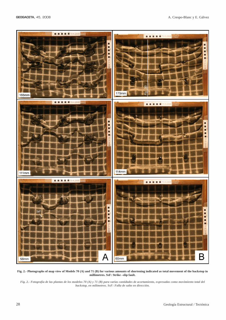
Fig. 2.- Photographs of map view of Models 70 (A) and 71 (B) for various amounts of shortening indicated as total movement of the backstop inmillimetres. SsF: Strike –slip fault.
Fig. 2.- Fotografía de las plantas de los modelos 70 (A) y 71 (B) para varias cantidades de acortamiento, expresadas como movimiento total delbackstop, en milímetros. SsF: Falla de salto en dirección.
Geología Estructural / Tectónica
A. Crespo-Blanc y E. Gálvez

29
GEOGACETA, 45, 2008
Sociedad Geológica de España
Weijermars et al., 1993; Cotton and Koyi,2000), respectively. Dry quartz sand wasused, with a grain size varying between 0.2and 0.3 mm, a coefficient of internal frictionφ = 37º, and density ρbM = 1.77 g/cm3.Coloured sand provided horizontalpassive markers within the undeformedexperimental multilayer. The siliconeputty used in our experiments(transparent Rhodosil Gum FB of Rhone-Poulenc) is a Newtonian material, with adensity ρdM = 0.98 gr cm-3 and a viscosityηM = 0.5 x 10⁵Pa s at room temperature.
The experiments were performed in a52cmx52cm sandbox schematicallyillustrated in Figure 1. Wood strips wereused to confine the whole model, and adrafting film sheet floored the sandbox.The sheet was pulled at a constant rate of2.25 x 10-6m s-1 (0.81cm h-1) by an electricmotor, causing the collision of theundeformed multilayer against the rigid,vertical backstop (Fig. 1). Therheological stratification of theundeformed model consisted of: i) alower ductile layer of silicone putty(0.5cm thick), over which nine cylindersof silicone simulated diapirs (1cm thick,from the top of the silicone basal layer tothe top of the cylinder), and (ii) an upperbrittle layer (1cm thick) composed ofalternating layers of coloured anduncoloured dry sand. The nine diapirs aresituated initially along a square whichsides are perpendicular to and parallelwith the backstop. They are separated15cm from each other (Fig. 1). Thediameter of the diapirs varies: 3.8cm inModel 70, and 2.1cm in Model 71. Thetotal shortening is similar for bothexperiments: 16.6cm and 17.9cm,respectively. A 4cm-side grid was sievedon top of the multilayer, including thediapirs. After completion, each modelunderwent serial sectioning parallel to theshortening direction.
Effects of diapirs on structural trendof the fold-and-thrust belt
The progressive deformation of themodels with diapirs of two different sizesis illustrated by photographs of the topsurface for various amounts of shortening(Fig. 2A and 2B). A general progressionof the deformation from the frontal to therear part of the model can be oberved. Inboth models, shortening is associatedmainly with box folds, accompanied bytheir corresponding forward and rearwardvergent thrusts, which developed almostsimultaneously. The photograph of Figu-re 3A shows a representative cross-section that illustrates the finite 2D
geometry. A very low surface wedge taperenhanced by the lack of dominantvergence, is also clearly illustrated withthe oblique photographs of the final stageof Model 71 (Fig. 3B). In Figures 2 and3B, silicone that reached the surface ofthe sandpack can be observed. Indeed,when shortening proceed, buoyancy-driven processes were enhanced, thesilicone were squeezed and the diapirsgrew until the silicone reached the top ofthe model.
The box-folds and thrust nucleated onthe diapirs, linking the closest ones.Accordingly, as the diapirs are initiallyregularly distributed (Fig. 1), twopossibilities exist concerning theorientation of the folds and thrusts: eithersubparallel to the backstop in the case ofthe smallest diapirs (Model 71), or at 45ºof the backstop when the diapirs arebroader (Model 70).
In the case of the smallest diapirs, thefirst compressive structures developed inthe most external part of the model, linkingthe diapirs parallel to the backstop. Theyshow a feston-like structural trend, convextowards the backstop (Fig. 2B). The anglebetween the laterals of the feston-likestructures is around 130º. Whenshortening proceed, a transfer zonedeveloped on the central diapir of themodel, linking two thrusts with oppositevergence. Its progression is shown in thecentral part of Figure 2B. Its finalgeometry is also illustrated on the obliquephotograph of Fig. 3B (TZ). In the finalstage of Model 71, the box folds areroughly cylindrical and subparallel to the
backstop, with exception of the structuresdragged by the wood strips which confinelaterally the silicone and sandpack.
Fig. 3.- A. Cross-section representative of the structural style of the experimental wedges.(localized in the final stage of Model 71, Fig. 2B). Dashed white line: boundary between sand
and silicone. B. Oblique view of the final stage of Model 71. TZ: Transfer Zone.
Fig. 3.- A. Corte representativo del estilo estructural de una cuña experimental (localizado en elestadio final del Modelo 71, Fig. 2B). Línea punteada: límite entre arena y silicona. B. Vista
oblicua del estadio final del Modelo 71. TZ: Zona de Transferencia.
Fig. 4.- Rose diagrams illustrating thestructural trend of the models (A, B) and of
the central Subbetic (C, Crespo-Blanc,2008).
Fig. 4.- Diagrama de rosas ilustrando elpatrón estructural de los modelos (A, B) y delSubbetico central (C, Crespo-Blanc, 2008).
Analogue modelling of non-cylindric fold-and-thrust belt around diapirs

30
GEOGACETA, 45, 2008
When the diapirs are broader, the finalresult is much less cylindrical (Model 70,Fig 2A). In the first stage of the experiment,it can be seen how the box-folds and thrustgenerated on the diapirs, as in the previousmodel. Nevertheless, in this case, they linkthe diapirs along diagonals of the squaredefined by adjacent diapirs. Accordingly,they are oriented at an angle of 45º withrespect to the backstop. As the structuresdeveloped simultaneously along bothdiagonals, they join in the square center,drawing a knee-like structural trend, inwhich both part of the knee are at an angleof 90º. Moreover, in this model, a discretestrike slip fault (SsF of Fig.2A) evolvinglater to an oblique thrust is observed. Whenshortening proceed, the box-folds andthrust generated in the first stage of theexperiments are slightly rotated andreached a position more parallel to thebackstop.
Discussion and concluding remarks
The experiments presented in thispaper show that in a sand pack situatedover a silicone layer, silicone cylindersrepresent a mechanical weakness whichis high enough to enhance the nucleationof compressive structures whenshortening take place. These structuresare box folds accompanied by theircorresponding forward and rearwardvergent thrusts, characteristic of thedeformation of a sandpack above aductile substrate (e.g. Cotton and Koyi,2000; Bahroudi and Koyi, 2003; Luján etal., 2003).
The generated structures linkadjacent cylinders, whose diameter is animportant factor which controlled thestructural trend and the degree ofcylindricity of the fold-and-thrust belt.The spatial distribution of the structuresand their grade of obliquity can bequantified through rose diagrams (Fig. 4).On the photographs of the final stage, thestructure lines were divided intosegments of 2cm length and their meanorientation measured. The north of therose diagrams corresponds to the
backstop movement and each petalrepresents a variation of 5º of strikeorientation. The folds and thrusts situatedat less than 4cm from the lateral woodstrips that confined the models were notconsidered, as they were twisted by thefriction of the strips. In our experiments,smaller diapirs are less efficient forproducing lack of cylindricity. Indeed,the rose diagram of Model 71 shows asmaller orientation variation of thestructures than that of Model 70, wherethe silicone cylinders are broader (Fig.4A and B).
It must be stressed that both modelspresented in this paper belong to a seriesof experiments raised to address theorigin of strong variations of thestructural trend of the Subbetic fold-and-thrust belt observed in the central Betics(Crespo-Blanc, 2007). Rose diagram Crepresents the variations of structuraltrend for that area (Fig. 4). It wasconstructed in order to respect the scalingfactor, that is, the quotient between thephysical parameters such as length,density or viscosity of the materials inboth the model and the natural case. Asthis scale factor is 2x10⁵, the structurallines of the Subbetic fold-and-thrust beltof the central Betics were divided intosegments of 4 km length, and their meanorientation was measured. The north ofthe stereoplot corresponds to thesupposed compression direction (seemore explanations in Crespo-Blanc,2008). By comparing diagrams A and B(models) with diagram C (natural case), itcan be observed that the structural trendof the central Subbetic shows a muchhigher variation then the modelspresented in this paper. Accordingly, thepresence of diapirs previous to theSubbetic fold-and-thrust belt formation isnot sufficient to induce such trendvariation, at least with the initialgeometric distribution of Models 70 and71. More analogue modelling withdifferent geometries of the siliconecylinder (size, position with respect to thebackstop, height, ...) should be realized inorder to test if the presence of diapirs
before the main compressional event isresponsible for the structural variation inthe Subbetic units of the central Betics.
Acknowledgments
This study was supported by grantsCGL2006-08638/BTE, CTM2005-08071-C03-01/MAR, CONSOLIDER-Ingenio nº CSD2006-00041 (Topo-Iberia) and RNM-215 (Junta de Andalu-cía).
References
Bahroudi, A. and Koyi, H.A. (2003).Journal of the Geological Society ofLondon, 160, 719-733.
Cotton, J. and Koyi, H.A. (2000). Geolo-gical Society of America Bulletin, 112/3, 351-363.
Crespo-Blanc, A. (2007). Journal of thegeological Society of London, 164/2,621-636.
Crespo-Blanc, A. (2008). Journal ofStructural Geology, 30, 65-80.
Davy, P. and Cobbold, P. R. (1991). Tec-tonophysics, 188, 1-25.
Likorish, W.H., Ford, M., Bürgisser, J.and Cobbold, P.R. (2002). GeologicalSociety of America Bulletin, 114, 1089-1107.
Luján, M., F. Storti, Balanyá, J.C., Cres-po-Blanc, A. and Rossetti, F. (2003).Journal of Structural Geology, 25, 867-881.
Molinaro, M., Guézou, J.C., Leturmy, P.,Eshraghi, S.A. and Frizon de Lamotte,D. (2004). Marine and Petroleum Geo-logy, 21/6, 735-752.
Roca, E., Sans, M. and Koyi, H.A.(2006). AAPG Bulletin, 90/1, 115-136.
Rowan, M. and Vendeville, B. (2006).Marine and Petroleum geology, 23,871-891.
Sanz de Galdeano, C. (1973) Geología dela transversal Jaén- Frailes (provinciade Jaén). Tesis Doctoral, Univ. Grana-da, 274pp.
Weijermars, R., Jackson, M.P.A. and Ven-deville, B. (1993). Tectonophysics,217, 143-174.
A. Crespo-Blanc y E. Gálvez
Geología Estructural / Tectónica