analog interfacing - hanyangccrs.hanyang.ac.kr/webpage_limdj/microprocessor/analog.pdf · analog...
TRANSCRIPT

ATmega128
Analog Interfacing
Waveform Sampling and Quantization
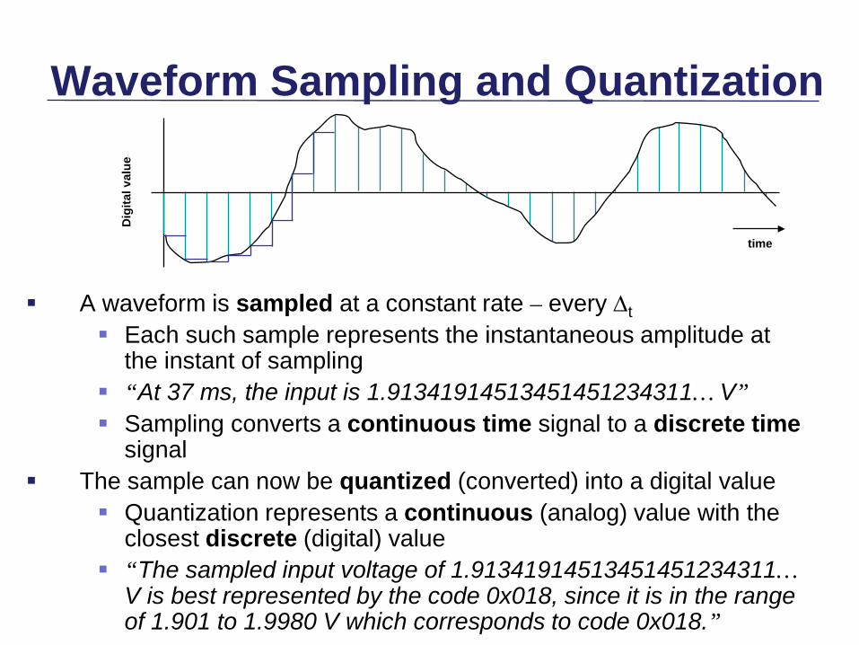
A waveform is sampled at a constant rate – every ∆t Each such sample represents the instantaneous amplitude at
the instant of sampling “At 37 ms, the input is 1.91341914513451451234311… V” Sampling converts a continuous time signal to a discrete time
signal The sample can now be quantized (converted) into a digital value
Quantization represents a continuous (analog) value with the closest discrete (digital) value
“The sampled input voltage of 1.91341914513451451234311… V is best represented by the code 0x018, since it is in the range of 1.901 to 1.9980 V which corresponds to code 0x018.”
time
Dig
ital v
alue

Sample and Hold Devices
Some A/D converters require the input analog signal to be held constant during conversion, (eg. successive approximation devices)
In other cases, peak capture or sampling at a specific point in time necessitates a sampling device.
This function is accomplished by a sample and hold device as shown to the right:
These devices are incorporated into some A/D converters
Analog InputSignal
Samplingswitch
HoldCapacitor
OutputSignal

A/D Converter

A/D Converter
Multi-comparator “flash” Integrating Tracking (counter-comparator) Successive approximation

Multi-comparator “flash”

Integrating

Tracking (counter-comparator)

Successive approximation

D/A Converter

D/A Converter

PWM (Pulse Width Modulation)

PWM (Pulse Width Modulation)

ATmega128 ADC

ADC Multiplexer Selection Register

ADC Multiplexer Selection Register

ADC Control & Status Register

ADC Control & Status Register

ADC Data Register

ADC Differential Mode

Timer PWM mode

Timer PWM mode

Timer PWM mode

Timer PWM mode
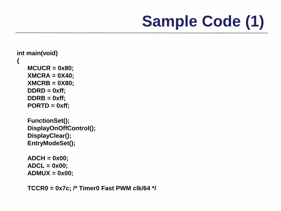
Sample Code (1)
int main(void) { MCUCR = 0x80; XMCRA = 0X40; XMCRB = 0X80; DDRD = 0xff; DDRB = 0xff; PORTD = 0xff; FunctionSet(); DisplayOnOffControl(); DisplayClear(); EntryModeSet(); ADCH = 0x00; ADCL = 0x00; ADMUX = 0x00; TCCR0 = 0x7c; /* Timer0 Fast PWM clk/64 */

Sample Code (2)
while(1) { ADCSR = 0xc7; while((ADCSR & 0x10)==0); ADC_L = ADCL; ADC_H = ADCH; PORTD = ~(ADC_L << 4); OCR0=(ADC_L>>2) | (ADC_H<<6); ADC_RESULT = 0x00; ADC_RESULT = ADC_RESULT | ADC_H; ADC_RESULT = 0x0300 & (ADC_RESULT << 8); ADC_RESULT = ADC_RESULT | ADC_L;

Sample Code (3)
c4 = ADC_RESULT / 1000; c3 = (ADC_RESULT % 1000) / 100; c1 = ADC_RESULT % 100; c2 = c1/10; c1 = c1 % 10; SetLCDAddress(LINE1); DisplayString((unsigned char*)"ADC:"); DisplayChar(c4+0x30); DisplayChar(c3+0x30); DisplayChar(c2+0x30); DisplayChar(c1+0x30); delay_ms(5); } }