an3966 application note - st.com · lwip tcp/ip stack demonstration for stm32f4x7 microcontrollers...
TRANSCRIPT
July 2013 DocID022105 Rev 2 1/48
AN3966Application note
LwIP TCP/IP stack demonstration for STM32F4x7 microcontrollers
IntroductionSTM32F4x7 microcontrollers feature a high-quality 10/100 Mbit/s Ethernet peripheral that supports both Media Independent Interface (MII) and Reduced Media Independent Interface (RMII) to interface with the Physical Layer (PHY).
When working with an Ethernet communication interface, a TCP/IP stack is mostly used to communicate over a local or a wide area network.
This application note presents a demonstration package built on top of the LwIP (Lightweight IP) TCP/IP stack which is an open source stack intended for embedded devices.
This demonstration package contains nine applications running on top of the LwIP stack:• Applications running in standalone mode (without an RTOS):
– A Web server– A TFTP server– A TCP echo client application– A TCP echo server application– A UDP echo client application– A UDP echo server application
• Applications running with the FreeRTOS operating system:– A Web server based on netconn API– A Web server based on socket API– A TCP/UDP echo server application based on netconn API
Note: In this document STM32F4x7 refers to STM32F407xx, STM32F417xx, STM32F427xx and STM32F437xx devices.
Table 1. Applicable productsType Product series
Microcontroller STM32F407xx, STM32F417xx, STM32F427xx, STM32F437xx
www.st.com

Contents AN3966
2/48 DocID022105 Rev 2
Contents
1 LwIP stack overview . . . . . . . . . . . . . . . . . . . . . . . . . . . . . . . . . . . . . . . . . 61.1 Stack features . . . . . . . . . . . . . . . . . . . . . . . . . . . . . . . . . . . . . . . . . . . . . . . 6
1.2 Folder organization of the LwIP stack . . . . . . . . . . . . . . . . . . . . . . . . . . . . 7
1.3 LwIP API overview . . . . . . . . . . . . . . . . . . . . . . . . . . . . . . . . . . . . . . . . . . . 71.3.1 Raw API . . . . . . . . . . . . . . . . . . . . . . . . . . . . . . . . . . . . . . . . . . . . . . . . . . 7
1.3.2 Netconn API . . . . . . . . . . . . . . . . . . . . . . . . . . . . . . . . . . . . . . . . . . . . . . . 9
1.3.3 Socket API . . . . . . . . . . . . . . . . . . . . . . . . . . . . . . . . . . . . . . . . . . . . . . . . 9
1.4 LwIP buffer management . . . . . . . . . . . . . . . . . . . . . . . . . . . . . . . . . . . . . 101.4.1 Packet buffer structure . . . . . . . . . . . . . . . . . . . . . . . . . . . . . . . . . . . . . . 10
1.4.2 API for managing pbufs . . . . . . . . . . . . . . . . . . . . . . . . . . . . . . . . . . . . . 11
1.5 Interfacing LwIP to STM32F4x7 Ethernet network interface . . . . . . . . . . 12
2 STM32F4x7 low level driver overview . . . . . . . . . . . . . . . . . . . . . . . . . . 132.1 Global Ethernet MAC/DMA functions . . . . . . . . . . . . . . . . . . . . . . . . . . . . 13
2.1.1 Ethernet MAC/DMA configuration parameters . . . . . . . . . . . . . . . . . . . 14
2.2 DMA descriptor handling . . . . . . . . . . . . . . . . . . . . . . . . . . . . . . . . . . . . . 172.2.1 DMA descriptors . . . . . . . . . . . . . . . . . . . . . . . . . . . . . . . . . . . . . . . . . . 17
2.2.2 DMA descriptor handling functions . . . . . . . . . . . . . . . . . . . . . . . . . . . . 19
2.3 PHY control functions . . . . . . . . . . . . . . . . . . . . . . . . . . . . . . . . . . . . . . . . 20
2.4 Hardware checksum . . . . . . . . . . . . . . . . . . . . . . . . . . . . . . . . . . . . . . . . . 21
3 Developing applications with LwIP stack . . . . . . . . . . . . . . . . . . . . . . . 223.1 Developing in standalone mode using the Raw API . . . . . . . . . . . . . . . . 22
3.1.1 Model of operation . . . . . . . . . . . . . . . . . . . . . . . . . . . . . . . . . . . . . . . . . 22
3.1.2 Example of the TCP echo server demo . . . . . . . . . . . . . . . . . . . . . . . . . 23
3.2 Developing with an RTOS using Netconn or Socket API . . . . . . . . . . . . . 263.2.1 Model of operation . . . . . . . . . . . . . . . . . . . . . . . . . . . . . . . . . . . . . . . . . 26
3.2.2 Example of a TCP echoserver demo using the Netconn API . . . . . . . . 27
3.3 LwIP memory configuration options . . . . . . . . . . . . . . . . . . . . . . . . . . . . . 29
4 Description of the demonstration package . . . . . . . . . . . . . . . . . . . . . 314.1 Package directories . . . . . . . . . . . . . . . . . . . . . . . . . . . . . . . . . . . . . . . . . 31
4.2 Demonstration settings . . . . . . . . . . . . . . . . . . . . . . . . . . . . . . . . . . . . . . . 32
DocID022105 Rev 2 3/48
AN3966 Contents
3
4.2.1 PHY interface configuration . . . . . . . . . . . . . . . . . . . . . . . . . . . . . . . . . . 32
4.2.2 MAC and IP address settings . . . . . . . . . . . . . . . . . . . . . . . . . . . . . . . . 32
4.2.3 STM324xx-EVAL settings . . . . . . . . . . . . . . . . . . . . . . . . . . . . . . . . . . . 32
5 Using the demos . . . . . . . . . . . . . . . . . . . . . . . . . . . . . . . . . . . . . . . . . . . 335.1 Standalone demos . . . . . . . . . . . . . . . . . . . . . . . . . . . . . . . . . . . . . . . . . . 33
5.1.1 Httpserver demo . . . . . . . . . . . . . . . . . . . . . . . . . . . . . . . . . . . . . . . . . . 33
5.1.2 TCP echo client demo . . . . . . . . . . . . . . . . . . . . . . . . . . . . . . . . . . . . . . 35
5.1.3 TCP echo server demo . . . . . . . . . . . . . . . . . . . . . . . . . . . . . . . . . . . . . 37
5.1.4 UDP echo client demo . . . . . . . . . . . . . . . . . . . . . . . . . . . . . . . . . . . . . . 39
5.1.5 UDP echo server demo . . . . . . . . . . . . . . . . . . . . . . . . . . . . . . . . . . . . . 40
5.1.6 TFTP server demo . . . . . . . . . . . . . . . . . . . . . . . . . . . . . . . . . . . . . . . . . 41
5.2 FreeRTOS demos . . . . . . . . . . . . . . . . . . . . . . . . . . . . . . . . . . . . . . . . . . 425.2.1 HTTP server netconn demo . . . . . . . . . . . . . . . . . . . . . . . . . . . . . . . . . . 42
5.2.2 HTTP server socket demo . . . . . . . . . . . . . . . . . . . . . . . . . . . . . . . . . . . 43
5.2.3 UDP TCP echo server netconn demo . . . . . . . . . . . . . . . . . . . . . . . . . . 43
6 Footprint information . . . . . . . . . . . . . . . . . . . . . . . . . . . . . . . . . . . . . . . 446.1 HTTP server demo . . . . . . . . . . . . . . . . . . . . . . . . . . . . . . . . . . . . . . . . . . 44
6.2 HTTP server netconn demo . . . . . . . . . . . . . . . . . . . . . . . . . . . . . . . . . . . 44
7 Conclusion . . . . . . . . . . . . . . . . . . . . . . . . . . . . . . . . . . . . . . . . . . . . . . . . 46
8 Revision history . . . . . . . . . . . . . . . . . . . . . . . . . . . . . . . . . . . . . . . . . . . 47

List of tables AN3966
4/48 DocID022105 Rev 2
List of tables
Table 1. Applicable products . . . . . . . . . . . . . . . . . . . . . . . . . . . . . . . . . . . . . . . . . . . . . . . . . . . . . . . 1Table 2. TCP Raw API functions . . . . . . . . . . . . . . . . . . . . . . . . . . . . . . . . . . . . . . . . . . . . . . . . . . . . 8Table 3. UDP Raw API functions . . . . . . . . . . . . . . . . . . . . . . . . . . . . . . . . . . . . . . . . . . . . . . . . . . . . 8Table 4. Netconn API functions . . . . . . . . . . . . . . . . . . . . . . . . . . . . . . . . . . . . . . . . . . . . . . . . . . . . . 9Table 5. Socket API functions. . . . . . . . . . . . . . . . . . . . . . . . . . . . . . . . . . . . . . . . . . . . . . . . . . . . . . . 9Table 6. Pbuf API functions . . . . . . . . . . . . . . . . . . . . . . . . . . . . . . . . . . . . . . . . . . . . . . . . . . . . . . . 11Table 7. ethernet_if.c functions description . . . . . . . . . . . . . . . . . . . . . . . . . . . . . . . . . . . . . . . . . . . 12Table 8. Global Ethernet MAC/DMA functions . . . . . . . . . . . . . . . . . . . . . . . . . . . . . . . . . . . . . . . . . 13Table 9. MAC configuration parameters of an ETH_InitTypeDef structure. . . . . . . . . . . . . . . . . . . . 14Table 10. DMA configuration parameters of an ETH_InitTypeDef structure. . . . . . . . . . . . . . . . . . . . 16Table 11. DMA descriptor functions . . . . . . . . . . . . . . . . . . . . . . . . . . . . . . . . . . . . . . . . . . . . . . . . . . 19Table 12. PHY control functions . . . . . . . . . . . . . . . . . . . . . . . . . . . . . . . . . . . . . . . . . . . . . . . . . . . . . 20Table 13. LwIP memory configuration options . . . . . . . . . . . . . . . . . . . . . . . . . . . . . . . . . . . . . . . . . . 29Table 14. STM324xx-EVAL jumper configurations. . . . . . . . . . . . . . . . . . . . . . . . . . . . . . . . . . . . . . . 32Table 15. HTTP server demo footprint . . . . . . . . . . . . . . . . . . . . . . . . . . . . . . . . . . . . . . . . . . . . . . . . 44Table 16. Httpserver netconn demo footprint . . . . . . . . . . . . . . . . . . . . . . . . . . . . . . . . . . . . . . . . . . . 45Table 17. Document revision history . . . . . . . . . . . . . . . . . . . . . . . . . . . . . . . . . . . . . . . . . . . . . . . . . 47

DocID022105 Rev 2 5/48
AN3966 List of figures
5
List of figures
Figure 1. LwIP folder organization . . . . . . . . . . . . . . . . . . . . . . . . . . . . . . . . . . . . . . . . . . . . . . . . . . . . 7Figure 2. Pbuf structure . . . . . . . . . . . . . . . . . . . . . . . . . . . . . . . . . . . . . . . . . . . . . . . . . . . . . . . . . . . 10Figure 3. Ethernet DMA descriptor . . . . . . . . . . . . . . . . . . . . . . . . . . . . . . . . . . . . . . . . . . . . . . . . . . 17Figure 4. Ethernet DMA descriptor chaining . . . . . . . . . . . . . . . . . . . . . . . . . . . . . . . . . . . . . . . . . . . 17Figure 5. STM32F4x7 Ethernet driver buffers and descriptors . . . . . . . . . . . . . . . . . . . . . . . . . . . . . 18Figure 6. Tracking DMA Rx/Tx descriptors to Get/Set . . . . . . . . . . . . . . . . . . . . . . . . . . . . . . . . . . . . 20Figure 7. Standalone operation model . . . . . . . . . . . . . . . . . . . . . . . . . . . . . . . . . . . . . . . . . . . . . . . . 22Figure 8. LwIP operation model with RTOS . . . . . . . . . . . . . . . . . . . . . . . . . . . . . . . . . . . . . . . . . . . 26Figure 9. Demonstration package structure. . . . . . . . . . . . . . . . . . . . . . . . . . . . . . . . . . . . . . . . . . . . 31Figure 10. Home page of the HTTP server demo . . . . . . . . . . . . . . . . . . . . . . . . . . . . . . . . . . . . . . . . 34Figure 11. SSI use in HTTP server demo application . . . . . . . . . . . . . . . . . . . . . . . . . . . . . . . . . . . . . 35Figure 12. TCP echo client demo . . . . . . . . . . . . . . . . . . . . . . . . . . . . . . . . . . . . . . . . . . . . . . . . . . . . 36Figure 13. TCP echo server demo. . . . . . . . . . . . . . . . . . . . . . . . . . . . . . . . . . . . . . . . . . . . . . . . . . . . 38Figure 14. UDP echo client demo . . . . . . . . . . . . . . . . . . . . . . . . . . . . . . . . . . . . . . . . . . . . . . . . . . . . 39Figure 15. UDP echo server demon . . . . . . . . . . . . . . . . . . . . . . . . . . . . . . . . . . . . . . . . . . . . . . . . . . 41Figure 16. TFTP tool (tftpd32) . . . . . . . . . . . . . . . . . . . . . . . . . . . . . . . . . . . . . . . . . . . . . . . . . . . . . . . 42

LwIP stack overview AN3966
6/48 DocID022105 Rev 2
1 LwIP stack overview
1.1 Stack featuresLwIP is a free TCP/IP stack developed by Adam Dunkels at the Swedish Institute of Computer Science (SICS) and licensed under a modified BSD license.
The focus of the LwIP TCP/IP implementation is to reduce the RAM use while still having a full scale TCP/IP stack. This makes LwIP suitable for use in embedded systems.
LwIP comes with the following protocols:• IPv4 and IPv6 (Internet Protocol v4 and v6)• ICMP (Internet Control Message Protocol) for network maintenance and debugging• IGMP (Internet Group Management Protocol) for multicast traffic management• UDP (User Datagram Protocol)• TCP (Transmission Control Protocol)• DNS (Domain Name Server)• SNMP (Simple Network Management Protocol)• DHCP (Dynamic Host Configuration Protocol)• PPP (Point to Point Protocol)• ARP (Address Resolution Protocol)
LwIP has three application programming interface (API) sets:• Raw API is the native API of LwIP. It enables the development of applications using
event callbacks. This API provides the best performance and code size, but adds some complexity for application development.
• Netconn API is a high-level sequential API that requires the services of a real-time operating system (RTOS). The Netconn API enables multi-threaded operations.
• BSD Socket API: Berkeley-like Socket API (developed on top of the Netconn API)
The source code for the LwIP stack can be downloaded at the following link: http://savannah.nongnu.org/projects/LwIP
Note: This application note is based on LwIP v1.4.1

DocID022105 Rev 2 7/48
AN3966 LwIP stack overview
47
1.2 Folder organization of the LwIP stackWhen unzipped, the LwIP stack files can be found under “\Utilities\Third_Party\LwIP-1.4.1” as shown in Figure 1.
Figure 1. LwIP folder organization
• doc: documentation text files• port/STM32F4x7: files implementing the LwIP port to STM32F4x7
– arch: STM32 architecture port files (used data types,...)– FreeRTOS: LwIP port to STM32F4x7 using FreeRTOS– Standalone: LwIP port to STM32F4x7 in Standalone mode
• src: source files of the LwIP stack– api: Netconn and Socket API files– core: LwIP core files– include: LwIP include files– netif: Network interface files
1.3 LwIP API overviewAs mentioned above, three types of APIs are offered by LwIP stack:• Raw API• Netconn API• Socket API
1.3.1 Raw APIThe Raw API is based on the native API of LwIP. It is used to develop callback-based applications.
When initializing the application, the user needs to register callback functions to different core events (such as TCP_Sent, TCP_error,...) . The callback functions will be called from the LwIP core layer when the corresponding event occurs.

LwIP stack overview AN3966
8/48 DocID022105 Rev 2
Table 2 provides a summary of the Raw API functions for TCP applications.
Table 3 provides a summary of the Raw API functions for UDP applications.
Table 2. TCP Raw API functionsAPI function Description
TCP connection setup
tcp_new Creates a new TCP PCB (protocol control block).
tcp_bind Binds a TCP PCB to a local IP address and port.
tcp_listen Starts the listening process on the TCP PCB.
tcp_accept Assigns a callback function that will be called when a new TCP connection arrives.
tcp_accepted Informs the LwIP stack that an incoming TCP connection has been accepted.
tcp_connect Connects to a remote TCP host.
Sending TCP data
tcp_write Queues up data to be sent.
tcp_sent Assigns a callback function that will be called when sent data is acknowledged by the remote host.
tcp_output Forces queued data to be sent.
Receiving TCP datatcp_recv Sets the callback function that will be called when new
data arrives.
tcp_recved Must be called when the application has processed the incoming data packet (for TCP window management).
Application polling tcp_poll
Assigns a callback functions that will be called periodically. It can be used by the application to check if there is remaining application data that needs to be sent or if there are connections that need to be closed.
Closing and aborting connections
tcp_close Closes a TCP connection with a remote host.
tcp_errAssigns a callback function for handling connections aborted by the LwIP due to errors (such as memory shortage errors).
tcp_abort Aborts a TCP connection.
Table 3. UDP Raw API functionsAPI function Description
udp_new Creates a new UDP PCB.
udp_remove Removes and de-allocates a UDP PCB.
udp_bind Binds a UDP PCB with a local IP address and port.
udp_connect Sets up a UDP PCB remote IP address and port.
udp_disconnect Removes a UDP PCB remote IP and port.
udp_send Sends UDP data.
udp_recv Specifies a callback function which is called when a datagram is received.

DocID022105 Rev 2 9/48
AN3966 LwIP stack overview
47
1.3.2 Netconn APIThe Netconn API is a high-level sequential API which has a model of execution based on the blocking open-read-write-close paradigm.
To function correctly, this API must run in a multi-threaded operation mode where there is a separate thread for the LwIP TCP/IP stack and one or multiple threads for the application.
Table 4 provides a summary of the Netconn API functions.
1.3.3 Socket APILwIP offers the standard BSD socket API. This is a sequential API which is internally built on top of the netconn.
Table 4 provides a summary of the main socket API functions.
Table 4. Netconn API functionsAPI function Description
netconn_new Creates a new connection.
netconn_delete Deletes an existing connection.
netconn_bind Binds a connection to a local IP address and port.
netconn_connect Connects to a remote IP address and port.
netconn_send Sends data to the currently connected remote IP/port (not applicable for TCP connections).
netconn_recv Receives data from a netconn.
netconn_listen Sets a TCP connection into a listening mode.
netconn_accept Accepts an incoming connection on a listening TCP connection.
netconn_write Sends data on a connected TCP netconn.
netconn_close Closes a TCP connection without deleting it.
Table 5. Socket API functionsAPI function Description
socket Creates a new socket.
bind Binds a socket to an IP address and port.
listen Listens for socket connections.
connect Connects a socket to a remote host IP address and port.
accept Accepts a new connection on a socket.
read Reads data from a socket.
write Writes data on a socket.
close Closes a socket (socket is deleted).

LwIP stack overview AN3966
10/48 DocID022105 Rev 2
1.4 LwIP buffer management
1.4.1 Packet buffer structureLwIP manages packet buffers using a data structure called pbuf. The pbuf structure enables the allocation of a dynamic memory to hold a packet content and lets packets reside in the static memory.
Pbufs can be linked together in a chain. This enables packets to span over several pbufs.
Figure 2. Pbuf structure
• next: pointer to next pbuf in a pbuf chain• payload: pointer to packet data payload• len: length of the data content of the pbuf• tot_len: sum of pbuf len plus all the len fields of the next pbufs in the chain• ref: (on 4 bits) reference count that indicates the number of pointers that reference the
pbuf. A pbuf can be released from memory only when its reference count is zero.• flags: (on 4 bits) indicate the type of pbuf.
LwIP defines three types of pbufs, depending on the allocation type:• PBUF_POOL: pbuf allocation is performed from a pool of statically pre-allocated pbufs
that have a predefined size. Depending on the data size that needs to be allocated, one or multiple chained pbufs are allocated.
• PBUF_RAM: pbuf is dynamically allocated in memory (one contiguous chunk of memory for the full pbuf)
• PBUF_ROM: there is no allocation for memory space for user payload, the pbuf payload pointer points to data in the ROM memory (it can be used only for sending constant data).
For packet reception, the suitable pbuf type is PBUF_POOL; it allows to rapidly allocate memory for the received packet from the pool of pbufs. Depending on the size of the received packet, one or multiple chained pbufs are allocated. The PBUF_RAM is not suitable for packet reception because dynamic allocation takes some delay. It may also lead to memory fragmentation.
For packet transmission, depending on the data to be transmitted, the user can choose the most suitable pbuf type.
next
payload
len
tot_len
flags refRoom for packet headers
next pbuf structure
MS18173V1

DocID022105 Rev 2 11/48
AN3966 LwIP stack overview
47
1.4.2 API for managing pbufsLwIP has a specific API for working with pbufs. This API is implemented in the pbuf.c core file.
Note: 1 “pbuf” can be a single pbuf or a chain of pbufs.
2 When working with the Netconn API, netbufs (network buffers) are used for sending/receiving data.
3 A netbuf is simply a wrapper for a pbuf structure. It can accommodate both allocated and referenced data.
4 A dedicated API (implemented in file netbuf.c) is provided for managing netbufs (allocating, freeing, chaining, extracting data,...).
Table 6. Pbuf API functionsAPI function Description
pbuf_alloc Allocates a new pbuf.
pbuf_realloc Resizes a pbuf (shrink size only).
pbuf_ref Increments the reference count field of a pbuf.
pbuf_free Decrements the pbuf reference count. If it reaches zero, the pbuf is de-allocated.
pbuf_clen Returns the count number of pbufs in a pbuf chain.
pbuf_cat Chains two pbufs together (but does not change the reference count of the tail pbuf chain).
pbuf_chain Chains two pbufs together (tail chain reference count is incremented).
pbuf_dechain Unchains the first pbuf from its succeeding pbufs in the chain.
pbuf_copy_partial Copies (part of) the contents of a packet buffer to an application supplied buffer.
pbuf_take Copies application supplied data into a pbuf.
pbuf_coalesce Creates a single pbuf out of a queue of pbufs.
LwIP stack overview AN3966
12/48 DocID022105 Rev 2
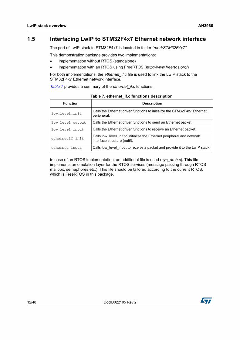
1.5 Interfacing LwIP to STM32F4x7 Ethernet network interfaceThe port of LwIP stack to STM32F4x7 is located in folder “/port/STM32F4x7”.
This demonstration package provides two implementations:• Implementation without RTOS (standalone)• Implementation with an RTOS using FreeRTOS (http://www.freertos.org/)
For both implementations, the ethernet_if.c file is used to link the LwIP stack to the STM32F4x7 Ethernet network interface.
Table 7 provides a summary of the ethernet_if.c functions.
In case of an RTOS implementation, an additional file is used (sys_arch.c). This file implements an emulation layer for the RTOS services (message passing through RTOS mailbox, semaphores,etc.). This file should be tailored according to the current RTOS, which is FreeRTOS in this package.
Table 7. ethernet_if.c functions descriptionFunction Description
low_level_initCalls the Ethernet driver functions to initialize the STM32F4x7 Ethernet peripheral.
low_level_output Calls the Ethernet driver functions to send an Ethernet packet.
low_level_input Calls the Ethernet driver functions to receive an Ethernet packet.
ethernetif_initCalls low_level_init to initialize the Ethernet peripheral and network interface structure (netif).
ethernet_input Calls low_level_input to receive a packet and provide it to the LwIP stack.

DocID022105 Rev 2 13/48
AN3966 STM32F4x7 low level driver overview
47
2 STM32F4x7 low level driver overview
The STM32F4x7 Ethernet low level driver is located in the \Libraries\STM32F4x7_ETH_Driver\ folder.
The set of functions provided in the driver can be divided into the following categories:• Global Ethernet MAC/DMA configuration/control functions • DMA descriptors handling functions • DMA configuration/control functions • PHY control functions • Power Management (PMT) functions • MAC Management Counters (MMC) functions
2.1 Global Ethernet MAC/DMA functionsTable 16 provides a summary of the Global Ethernet MAC/DMA functions used for the configuration of the media access control (MAC) and direct memory access (DMA) features.
Table 8. Global Ethernet MAC/DMA functionsFunction Description
ETH_DeInit Resets the Ethernet peripheral.
ETH_StructInit Fills a configuration structure for an Ethernet peripheral with the default config (see below).
ETH_Init Initializes the Ethernet peripheral (MAC/DMA) registers with the required configuration.
ETH_Start Starts the Ethernet MAC/DMA operation.
ETH_Stop Stops the Ethernet MAC/DMA operation.
ETH_MACTransmissionCmd Enables or disables MAC transmission.
ETH_MACReceptionCmd Enables or disables MAC reception.
ETH_GetFlowControlBusyStatus Checks flow control Busy flag.
ETH_InitiatePauseControlFrame Initiates a Pause frame (full-duplex only).
ETH_BackPressureActivationCmd Enables or disables Back pressure mechanism (half duplex mode).
ETH_GetMACFlagStatus Gets MAC flags status.
ETH_GetMACITStatus Gets MAC interrupts status.
ETH_MACITConfig Configures MAC interrupts.
ETH_MACAddressConfig Configures a MAC address.
ETH_GetMACAddress Gets configured MAC address.
ETH_MACAddressPerfectFilterCmd Enables or disables MAC perfect filtering for a selected MAC address.

STM32F4x7 low level driver overview AN3966
14/48 DocID022105 Rev 2
2.1.1 Ethernet MAC/DMA configuration parametersThe configuration structure for an Ethernet MAC/DMA is ETH_InitTypeDef.This structure is composed of the following MAC and DMA configuration parameters.
ETH_MACAddressFilterConfig Configures the MAC address filtering mode.
ETH_MACAddressMaskBytesFilterConfig
Selects MAC address bytes on which filtering will be performed.
Table 8. Global Ethernet MAC/DMA functions (continued)Function Description
Table 9. MAC configuration parameters of an ETH_InitTypeDef structureParameter Description Default value(1)
ETH_AutoNegotiation Enables PHY Auto-Negotiation. ETH_AutoNegotiation_Enable
ETH_Watchdog
Enables or disables Watchdog timer during frame reception.– When enabled, the MAC allows no more than
2048 bytes to be received.– When disabled, the MAC can receive up to
16384 bytes.
ETH_Watchdog_Enable
ETH_Jabber
– When enabled, the MAC allows no more than 2048 bytes to be sent.
– When disabled, the MAC can send up to 16384 bytes.
ETH_Jabber_Enable
ETH_InterFrameGapSelects the minimum IFG between frames during transmission. ETH_InterFrameGap_96Bit
ETH_CarrierSense Enables the Carrier Sense. ETH_CarrierSense_Enable
ETH_Speed Sets the Ethernet speed: 10/100 Mbps ETH_Speed_100M
ETH_ReceiveOwn
Enables the ReceiveOwn.ReceiveOwn enables the reception of frames when the TX_EN signal is asserted in Half-Duplex mode.
ETH_ReceiveOwn_Enable
ETH_LoopbackMode Enables the internal MAC MII Loopback mode. ETH_LoopbackMode_Disable
ETH_ModeSelects the MAC duplex mode: Half-Duplex or Full-Duplex mode ETH_Mode_FullDuplex
ETH_ChecksumOffloadEnables the IPv4 checksum checking for received frame payloads for TCP/UDP/ICMP packets.
ETH_ChecksumOffload_Disable
ETH_RetryTransmissionEnables the MAC attempt retries transmission when a collision occurs (Half-Duplex mode).
ETH_RetryTransmission_Enable
ETH_AutomaticPadCRCStrip
Enables the Automatic MAC Pad/CRC Stripping. ETH_AutomaticPadCRCStrip_Disable
ETH_BackOffLimit Selects the BackOff limit value. ETH_BackOffLimit_10

DocID022105 Rev 2 15/48
AN3966 STM32F4x7 low level driver overview
47
ETH_DeferralCheckEnables the deferral check function (Half-Duplex mode).
ETH_DeferralCheck_Disable
ETH_ReceiveAllEnables the reception of all frames by the MAC (No filtering). ETH_ReceiveAll_Disable
ETH_SourceAddrFilter Enables Source Address Filter mode. ETH_SourceAddrFilter_Disable
ETH_PassControlFramesSets the forwarding mode of the control frames (including unicast and multicast Pause frames).
ETH_PassControlFrames_BlockAll
ETH_BroadcastFramesReception
Enables the reception of Broadcast frames. ETH_BroadcastFramesReception_Disable
ETH_DestinationAddrFilter
Sets the destination filter mode for both unicast and multicast frames.
ETH_DestinationAddrFilter_Normal
ETH_PromiscuousMode Enables Promiscuous filtering mode. ETH_PromiscuousMode_Disable
ETH_MulticastFramesFilter
Selects the Multicast frames filter mode: None/HashTableFilter/PerfectFilter/PerfectHashTableFilter.
ETH_MulticastFramesFilter_Perfect
ETH_UnicastFramesFilterSelects the Unicast frames filter mode: HashTableFilter/PerfectFilter/PerfectHashTableFilter
ETH_UnicastFramesFilter_Perfect
ETH_HashTableHigh This field holds the higher 32 bits of Hash table. 0x0
ETH_HashTableLow This field holds the lower 32 bits of Hash table. 0x0
ETH_PauseTimeThis field holds the value to be used in the Pause Time field in the transmit of a control frame.
0x0
ETH_ZeroQuantaPauseEnables the automatic generation of Zero-Quanta Pause control frames.
ETH_ZeroQuantaPause_Disable
ETH_PauseLowThresholdConfigures the threshold of the Pause to be checked for automatic retransmission of Pause frame.
ETH_PauseLowThreshold_Minus4
ETH_UnicastPauseFrameDetect
Enables the MAC detection of the Pause frames (with MAC Address0 unicast address and unique multicast address).
ETH_UnicastPauseFrameDetect_Disable
ETH_ReceiveFlowControlEnables the MAC to decode the received Pause frame and disables its transmitter for a specified time (Pause Time).
ETH_ReceiveFlowControl_Disable
ETH_TransmitFlowControlEnables the MAC to transmit Pause frames (Full-Duplex mode) or the MAC back-pressure operation (Half-Duplex mode).
ETH_TransmitFlowControl_Disable
ETH_VLANTagComparisonSelects the 12-bit VLAN identifier or the complete 16-bit VLAN tag for comparison and filtering.
ETH_VLANTagComparison_16Bit
ETH_VLANTagIdentifier Holds the VLAN tag identifier for receive frames. 0x0
1. The Default Value is the value configured by calling the ETH_StructInit function.
Table 9. MAC configuration parameters of an ETH_InitTypeDef structure (continued)Parameter Description Default value(1)

STM32F4x7 low level driver overview AN3966
16/48 DocID022105 Rev 2
Table 10. DMA configuration parameters of an ETH_InitTypeDef structureParameter Description Default value
ETH_DropTCPIPChecksumErrorFrame
Enables the dropping of TCP/IP Checksum Error Frames.
ETH_DropTCPIPChecksumErrorFrame_Disable
ETH_ReceiveStoreForward Enables the Receive store and forward mode. ETH_ReceiveStoreForward_Enable
ETH_FlushReceivedFrame Enables the flushing of received frames. ETH_FlushReceivedFrame_Enable
ETH_TransmitStoreForward
Enables Transmit store and forward mode. ETH_TransmitStoreForward_Enable
ETH_TransmitThresholdControl
Selects of the threshold level of the Transmit FIFO.
ETH_TransmitThresholdControl_64Bytes
ETH_ForwardErrorFramesEnables the forward to the DMA of erroneous frames.
ETH_ForwardErrorFrames_Disable
ETH_ForwardUndersizedGoodFrames
Enables the Rx FIFO to forward Undersized frames (frames with no Error and length less than 64 bytes) including pad-bytes and CRC).
ETH_ForwardUndersizedGoodFrames_Disable
ETH_ReceiveThresholdControl
Selects the threshold level of the Receive FIFO. ETH_ReceiveThresholdControl_64Bytes
ETH_SecondFrameOperate
Enables the Operate on second frame mode, which enables the DMA to process a second frame of Transmit data even before obtaining the status for the first frame.
ETH_SecondFrameOperate_Disable
ETH_AddressAlignedBeats Enables address-aligned beats. ETH_AddressAlignedBeats_Enable
ETH_FixedBurstEnables AHB Master interface fixed burst transfers. ETH_FixedBurst_Enable
ETH_RxDMABurstLengthIndicates the number of beats in an Rx DMA burst transfer.
ETH_RxDMABurstLength_32Beat
ETH_TxDMABurstLengthIndicates the number of beats in a Tx DMA burst transfer.
ETH_TxDMABurstLength_32Beat
ETH_DescriptorSkipLength
Specifies the number of words to skip between two unchained descriptors (Ring mode). 0x0
ETH_DMAArbitration Selects the DMA Tx/Rx arbitration. ETH_DMAArbitration_RoundRobin_RxTx_1_1

DocID022105 Rev 2 17/48
AN3966 STM32F4x7 low level driver overview
47
2.2 DMA descriptor handling
2.2.1 DMA descriptorsThe transfer of Ethernet packets between Transmit/Receive FIFOs and memory is performed by direct memory access (DMA) using transfer descriptors.
Figure 3 illustrates the format of an Ethernet DMA descriptor.
Note: The following description does not apply to enhanced DMA descriptors.
Figure 3. Ethernet DMA descriptor
As shown in Figure 3, the DMA descriptor can have two formats:• The descriptor points to one data buffer only and the Next Descriptor field points on
next DMA descriptor for allowing descriptors chaining mechanism• The descriptor can point to two data buffers, Buffer1 and Buffer2
In the STM32F4x7 Ethernet driver, the selected DMA descriptor format is the one allowing descriptor chaining as shown in Figure 4.
Figure 4. Ethernet DMA descriptor chaining
Note: 1 An Ethernet packet can span over one or multiple DMA descriptors.
2 One DMA descriptor can be used for one Ethernet packet only.
3 The last descriptor in the chain points to the first descriptor for forming a ring of descriptors.
MS18176V1
Control / Status Information
Buffer1 Count / Buffer2 Count
Buffer1 Address
Buffer2 Address / Next Descriptor
Control / Status
Buffer Count
Buffer Address
Next Descriptor
Buffer1 Count & Buffer2 Count
Buffer1 Address
Buffer2 address
Control / Status
Buffer1
Buffer2
Control / Status
Buffer Count
Buffer Address
Next Descriptor
Option 1 Option 2
MS18177V1
Control / Status
Buffer Count
Buffer Address
Next Descriptor
Control / Status
Buffer Count
Buffer Address
Next Descriptor
Control / Status
Buffer Count
Buffer Address
Next Descriptor
Descriptor 0 Descriptor 1 Descriptor n
STM32F4x7 low level driver overview AN3966
18/48 DocID022105 Rev 2
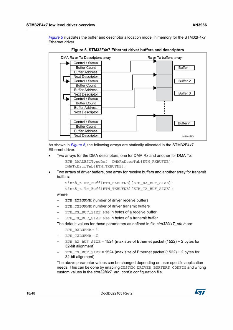
Figure 5 illustrates the buffer and descriptor allocation model in memory for the STM32F4x7 Ethernet driver.
Figure 5. STM32F4x7 Ethernet driver buffers and descriptors
As shown in Figure 5, the following arrays are statically allocated in the STM32F4x7 Ethernet driver:• Two arrays for the DMA descriptors, one for DMA Rx and another for DMA Tx:
ETH_DMADESCTypeDef DMARxDscrTab[ETH_RXBUFNB], DMATxDscrTab[ETH_TXBUFNB];
• Two arrays of driver buffers, one array for receive buffers and another array for transmit buffers:
uint8_t Rx_Buff[ETH_RXBUFNB][ETH_RX_BUF_SIZE];
uint8_t Tx_Buff[ETH_TXBUFNB][ETH_TX_BUF_SIZE];
where:– ETH_RXBUFNB: number of driver receive buffers– ETH_TXBUFNB: number of driver transmit buffers– ETH_RX_BUF_SIZE: size in bytes of a receive buffer– ETH_TX_BUF_SIZE: size in bytes of a transmit bufferThe default values for these parameters as defined in file stm32f4x7_eth.h are:– ETH_RXBUFNB = 4– ETH_TXBUFNB = 2– ETH_RX_BUF_SIZE = 1524 (max size of Ethernet packet (1522) + 2 bytes for
32-bit alignment)– ETH_TX_BUF_SIZE = 1524 (max size of Ethernet packet (1522) + 2 bytes for
32-bit alignment)The above parameter values can be changed depending on user specific application needs. This can be done by enabling CUSTOM_DRIVER_BUFFERS_CONFIG and writing custom values in the stm32f4x7_eth_conf.h configuration file.
MS18178V1
Control / StatusBuffer Count
Buffer AddressNext DescriptorControl / Status
Buffer Count
Buffer AddressNext DescriptorControl / Status
Buffer CountBuffer AddressNext Descriptor
DMA Rx or Tx Descriptors array Rx or Tx buffers array
Buffer 1
Buffer 2
Buffer 3
Buffer nControl / StatusBuffer Count
Buffer AddressNext Descriptor

DocID022105 Rev 2 19/48
AN3966 STM32F4x7 low level driver overview
47
Note: The Ethernet driver allows to have a buffer size (ETH_RX_BUF_SIZE or ETH_TX_BUF_SIZE) that does not exceed the maximum Ethernet packet size (1522 bytes). Ethernet packets (received or to be transmitted) exceeding the configured buffer size will span over multiple buffers (or descriptors).
2.2.2 DMA descriptor handling functionsTable 11 provides a summary of the main driver functions used for handling DMA descriptors.
Table 11. DMA descriptor functionsFunction Description
ETH_DMARxDescChainInit Initializes DMA Rx Descriptor chain (as shown in Figure 5).
ETH_DMATxDescChainInit Initializes DMA Tx Descriptor chain (as shown in Figure 5)
ETH_CheckFrameReceived Checks if the frame is received (polling method on OWN bit and other flags of DMA RX descriptor).
ETH_Get_Received_Frame Gets received frame (when using a polling method).
ETH_Get_Received_Frame_interrupt Gets received frame (when using an interrupt method for detecting received packets).
ETH_Prepare_Transmit_Descriptors Prepares DMA TX descriptors for transmitting a packet (data should already be copied in driver buffers).
ETH_GetRxPktSize Gets the size of a received packet.
ETH_GetDMATxDescFlagStatus Gets flag status of a DMA TX descriptor.
ETH_GetDMARxDescFlagStatus Gets flag status of a DMA RX descriptor.
ETH_DMATxDescTransmitITConfig Configures Interrupts for a DMA TX descriptor.
ETH_DMARxDescReceiveITConfig Configures Interrupts for a DMA RX descriptor.
ETH_EnhancedDescriptorCmd(1)
1. Enhanced descriptors must be used if IPv4 checksum offload is activated. The enhanced descriptor format is enabledeither by: uncommenting USE_ENHANCED_DMA_DESCRIPTORS in stm32f4x7_eth_conf.h file, or, by calling the ETH_EnhancedDescriptorCmd() function.
Enables or disables the Enhanced descriptor structure.
ETH_DMATxDescChecksumInsertionConfig
Enables or disables TCP/UDP/ICMP checksum insertion for transmitted packets.
ETH_DMATxDescCRCCmd Enables or disables CRC generation for transmitted packets.
ETH_DMATxDescShortFramePaddingCmd Enables or disables adding padding to short frame to be transmitted.

STM32F4x7 low level driver overview AN3966
20/48 DocID022105 Rev 2
Note: The Ethernet driver maintains two global pointers for Rx/Tx DMA descriptor tracking, for the next packet to be received or to be transmitted:
__IO ETH_DMADESCTypeDef *DMATxDescToSet;
__IO ETH_DMADESCTypeDef *DMARxDescToGet;
Figure 6. Tracking DMA Rx/Tx descriptors to Get/Set
2.3 PHY control functionsTable 12 provides a summary of the functions implemented for PHY control by the STM32F4x7 Ethernet driver.
Note: The PHY configuration options (Reset delay, Configuration delay, Status register Speed and Duplex mask values) are defined in the stm32f4x7_eth_conf.h configuration file. These values change from a PHY to another, so the user has to update this value depending on the external PHY used.
MS18179V1
Control / Status
Buffer Count
Buffer Address
Next Descriptor
Control / Status
Buffer Count
Buffer Address
Next Descriptor
Control / Status
Buffer Count
Buffer Address
Next Descriptor
Rx Descriptor 0 Rx Descriptor 1 Rx Descriptor n
DMARxDescToGet
Control / Status
Buffer Count
Buffer Address
Next Descriptor
Control / Status
Buffer Count
Buffer Address
Next Descriptor
Control / Status
Buffer Count
Buffer Address
Next Descriptor
Tx Descriptor 0 Tx Descriptor 1 Tx Descriptor nDMATxDescToSet
Table 12. PHY control functionsFunction Description
ETH_ReadPHYRegister Reads a PHY register.
ETH_WritePHYRegister Writes a data into a PHY register.
ETH_PHYLoopBackCmd Enables or disables the PHY loopback mode.
DocID022105 Rev 2 21/48
AN3966 STM32F4x7 low level driver overview
47
The PHY is mainly accessed during the initialization time (by ETH_Init driver function) to:• Reset the PHY.• Enable the PHY auto-negotiation mode or manually select the mode of operation (Full-
speed/Low-speed, Half-duplex/Full-duplex).• If the PHY auto-negotiation mode is selected, the application needs to poll the PHY or
use a PHY interrupt in order to obtain the result of auto-negotiation (speed, duplex mode).
2.4 Hardware checksumThe STM32F4x7 Ethernet controller has an embedded hardware checksum accelerator to off-load the CPU from generating, inserting and verifying the checksums of the IP, UDP, TCP and ICMP protocols.
The checksum for TCP, UDP or ICMP is calculated over a complete frame, and then inserted into its corresponding header field. Due to this requirement, this function is enabled only when the Transmit FIFO is configured for Store-and-Forward mode.
Note: By default, the hardware checksum is enabled. To disable this feature, “comment” the specific CHECKSUM_BY_HARDWARE defined in the LwIPopts.h file under the \inc project folder.

Developing applications with LwIP stack AN3966
22/48 DocID022105 Rev 2
3 Developing applications with LwIP stack
3.1 Developing in standalone mode using the Raw API
3.1.1 Model of operationIn standalone mode, the model of operation is based on continuous software polling to check if a packet is received.
When a packet is received, it is first copied from the Ethernet driver buffers into the LwIP buffers. In order to copy the packet as fast as possible, the LwIP buffers (pbufs) should be allocated from the pool of buffers (PBUF_POOL).
When a packet has been copied, it is handed to the LwIP stack for processing. Depending on the received packet, the stack may or may not notify the application layer.
LwIP communicates with the application layer using event callback functions. These functions should be assigned before starting the communication process.
Figure 7. Standalone operation model
Poll for packet reception
New packet received ?
Copy packet from driver buffers to lwiP buffers
Processing of the packet by the lwIP stack
Processing of application assigned callback function
Application notification needed?
No
No
Yes
Yes
MS18174V1

DocID022105 Rev 2 23/48
AN3966 Developing applications with LwIP stack
47
For TCP applications, the following common callback functions must be assigned:• callback for incoming TCP connection event, assigned by TCP_accept API call• callback for incoming TCP data packet event, assigned by TCP_recev API call• callback for signalling successful data transmission, assigned by TCP_sent API call• callback for signalling TCP error (after a TCP abort event), assigned by TCP_err API
call• Periodic callback (every 1 or 2 s) for polling the application, assigned by TCP_poll API
call
3.1.2 Example of the TCP echo server demoThe TCP echo server example provided in the \Project\Standalone\tcp_echo_server folder is a simple application that implements a TCP server which echoes any received TCP data packets coming from a remote client.
To test the demo, use echotool.exe PC client utility. This utility is located in the \Utilities\Third_Party\PC_Software folder. (Refer to Section 5.1.3: TCP echo server demo for more details about testing the demo).
The following example provides a description about the firmware structure. It is an extract from the main.c file.
int main(void){
...
/* configure Ethernet (GPIOs, clocks, MAC, DMA) */ ETH_BSP_Config(); /* Initilaize the LwIP stack */ LwIP_Init(); /* tcp echo server Init */ tcp_echoserver_init(); /* Infinite loop */ while (1) { /* check if any packet received */ if (ETH_CheckFrameReceived()) { /* process received Ethernet packet */ LwIP_Pkt_Handle(); } /* handle periodic timers for LwIP */ LwIP_Periodic_Handle(LocalTime); } }

Developing applications with LwIP stack AN3966
24/48 DocID022105 Rev 2
Example description:• ETH_BSP_Config function is called to initialize the Ethernet peripheral (GPIOs, Clocks,
MAC and DMA options).• LwIP_Init function is called to initialize the LwIP stack internal structures and for
starting stack operations.• tcp_echoserver_init function is called to initialize the TCP echo server application (see
below).• In the infinite while loop, software polls for packet reception using Ethernet driver
ETH_CheckFrameReceived function. When a packet is received, it should be handled by the LwIP stack using function LwIP_Pkt_Handle.
• LwIP_Periodic_Handle function is called in order to handle certain LwIP internal periodic tasks (protocol timers, retransmission of TCP packets,...).
Function tcp_echoserver_init has the following code:
void tcp_echoserver_init(void){ /* create new tcp pcb */ tcp_echoserver_pcb = tcp_new();
if (tcp_echoserver_pcb != NULL) { err_t err; /* bind echo_pcb to port 7 (ECHO protocol) */ err = tcp_bind(tcp_echoserver_pcb, IP_ADDR_ANY, 7); if (err == ERR_OK) { /* start tcp listening for echo_pcb */ tcp_echoserver_pcb = tcp_listen(tcp_echoserver_pcb); /* initialize LwIP tcp_accept callback function */ tcp_accept(tcp_echoserver_pcb, tcp_echoserver_accept); } else { printf("Can not bind pcb\n"); } } else { printf("Can not create new pcb\n"); }}

DocID022105 Rev 2 25/48
AN3966 Developing applications with LwIP stack
47
Example description:• LwIP API calls tcp_new to allocate a new TCP protocol control block (PCB)
(tcp_echoserver_pcb).• The allocated TCP PCB is bound to a local IP address and port using tcp_bind
function.• After binding the TCP PCB, tcp_listen function is called in order to start the TCP
listening process on the TCP PCB.• Finally a tcp_echoserver_accept callback function should be assigned to handle
incoming TCP connections on the TCP PCB. This is done using tcp_accept LwIP API function.
• Starting from this point, the TCP server is ready to accept any incoming connection from remote clients.
The following example shows how incoming TCP connections are handled by tcp_echoserver_accept user callback function. This is an extract from this function.
static err_t tcp_echoserver_accept(void *arg, struct tcp_pcb *newpcb, err_t err){
...
/* allocate structure es to maintain tcp connection infos */ es = (struct tcp_echoserver_struct *)mem_malloc(sizeof(struct tcp_echoserver_struct)); if (es != NULL) { es->state = ES_ACCEPTED; es->pcb = newpcb; es->p = NULL; /* pass newly allocated es structure as argument to newpcb */ tcp_arg(newpcb, es); /* initialize LwIP tcp_recv callback function for newpcb */ tcp_recv(newpcb, tcp_echoserver_recv); /* initialize LwIP tcp_err callback function for newpcb */ tcp_err(newpcb, tcp_echoserver_error); /* initialize LwIP tcp_poll callback function for newpcb */ tcp_poll(newpcb, tcp_echoserver_poll, 1); ret_err = ERR_OK;
...}
Developing applications with LwIP stack AN3966
26/48 DocID022105 Rev 2
Example description:• The new TCP connection is passed to tcp_echoserver_accept callback function
through newpcb parameter.• An es structure is used to maintain the application status. It is passed as an argument
to the TCP PCB “newpcb” connection by calling tcp_arg LwIP API.• A TCP receive callback function, tcp_echoserver_recv, is assigned by calling LwIP API
tcp_recv. This callback will handle all the data traffic with the remote client.• A TCP error callback function, tcp_echoserver_error, is assigned by calling LwIP API
tcp_err .This callback will handle TCP errors.• A TCP poll callback function, tcp_echoserver_poll, is assigned by calling LwIP API
tcp_poll to handle periodic application tasks (such as checking if the application data remains to be transmitted).
3.2 Developing with an RTOS using Netconn or Socket API
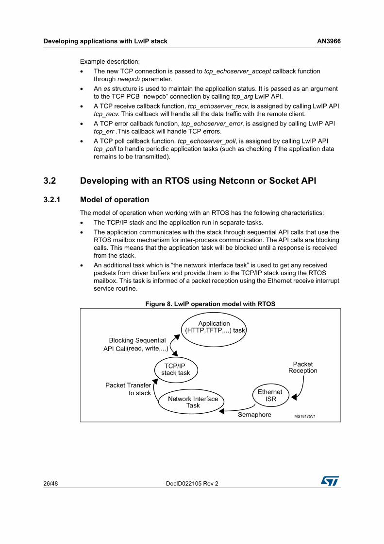
3.2.1 Model of operationThe model of operation when working with an RTOS has the following characteristics:• The TCP/IP stack and the application run in separate tasks.• The application communicates with the stack through sequential API calls that use the
RTOS mailbox mechanism for inter-process communication. The API calls are blocking calls. This means that the application task will be blocked until a response is received from the stack.
• An additional task which is “the network interface task” is used to get any received packets from driver buffers and provide them to the TCP/IP stack using the RTOS mailbox. This task is informed of a packet reception using the Ethernet receive interrupt service routine.
Figure 8. LwIP operation model with RTOS
MS18175V1
Application (HTTP,TFTP,...) task
TCP/IP stack task
Network InterfaceTask
Blocking Sequential
Packet Transferto stack
Packet Reception
Ethernet ISR
Semaphore
(read, write,...)API Call
DocID022105 Rev 2 27/48
AN3966 Developing applications with LwIP stack
47
3.2.2 Example of a TCP echoserver demo using the Netconn APIFrom the application point of view, the Netconn API offers a simpler way for developing TCP/IP applications other than the raw API. This is because it has a more intuitive sequential API.
The following example shows a TCP echoserver demo developed with the Netconn API. This is an extract of the main.c file.
void Main_task(void * pvParameters){ .../* configure ethernet (GPIOs, clocks, MAC, DMA) */ ETH_BSP_Config();/* Initialize the LwIP stack */ LwIP_Init();/* Initialize tcp echo server */ tcpecho_init();...
for( ;; ){ ... }}
Example description:• LwIP_Init function initializes the LwIP stack. This includes the creation of the LwIP
TCP/IP stack task.• tcpecho_thread TCP echo server task is created in tcpecho_init function.
void tcpecho_init(void){ sys_thread_new("tcpecho_thread", tcpecho_thread, NULL,\ DEFAULT_THREAD_STACKSIZE, TCPECHO_THREAD_PRIO);}
The TCP echo server thread has the following code:
static void tcpecho_thread(void *arg){ struct netconn *conn, *newconn; err_t err, accept_err; struct netbuf *buf; void *data; u16_t len; err_t recv_err; LWIP_UNUSED_ARG(arg);
/* Create a new connection identifier. */ conn = netconn_new(NETCONN_TCP);
Developing applications with LwIP stack AN3966
28/48 DocID022105 Rev 2
if (conn!=NULL) { /* Bind connection to well known port number 7. */ err = netconn_bind(conn, NULL, 7); if (err == ERR_OK) { /* Tell connection to go into listening mode. */ netconn_listen(conn); while (1) { /* Grab new connection. */ accept_err = netconn_accept(conn, &newconn); /* Process the new connection. */ if (accept_err == ERR_OK) {
while (( recv_err = netconn_recv(newconn, &buf)) == ERR_OK) { do { netbuf_data(buf, &data, &len); netconn_write(newconn, data, len, NETCONN_COPY); } while (netbuf_next(buf) >= 0); netbuf_delete(buf); } /* Close connection and discard connection identifier. */ netconn_close(newconn); netconn_delete(newconn); } } } else { netconn_delete(newconn); printf(" can not bind TCP netconn"); } } else { printf("can not create TCP netconn"); }}
DocID022105 Rev 2 29/48
AN3966 Developing applications with LwIP stack
47
Example description:• Netconn_new API function called with NETCONN_TCP parameter will create a new
TCP connection.• The newly created connection is then bound to port 7 (echo protocol) by calling
Netconn_bind API function.• After binding the connection, the application starts the listening process on the
connection by calling Netconn_listen API function.• In the infinite while(1) loop, the application waits for a new connection by calling the API
function Netconn_accept. This API call will block the application task when there is no incoming connection.
• When there is an incoming connection, the application can start receiving data by calling netconn_recv API function. Incoming data is received in a netbuf.
• The application can get the received data by calling netbuf_data netbuf API function.• The received data is sent back (echoed) to the remote TCP client by calling
Netconn_write API function.• Netconn_close and Netconn_delete are used to respectively close and delete the
Netconn connection.
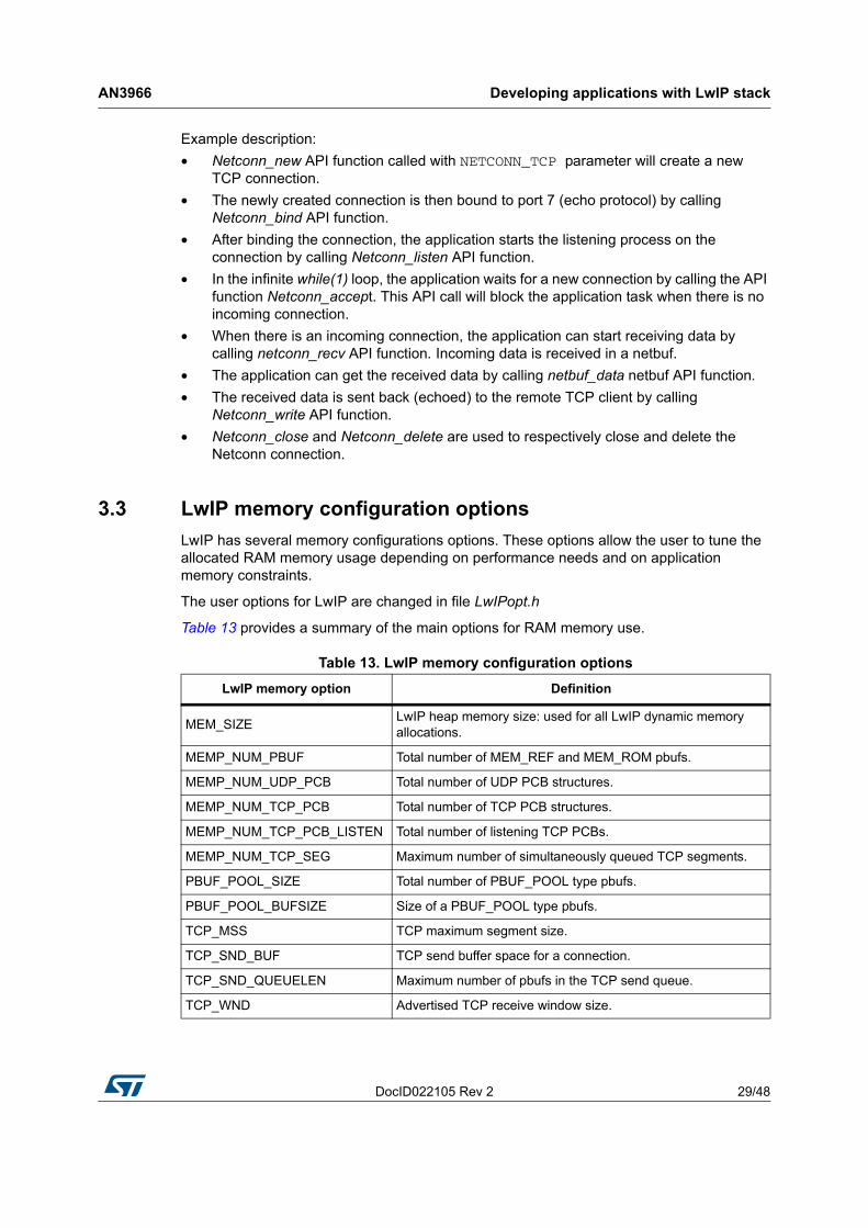
3.3 LwIP memory configuration optionsLwIP has several memory configurations options. These options allow the user to tune the allocated RAM memory usage depending on performance needs and on application memory constraints.
The user options for LwIP are changed in file LwIPopt.h
Table 13 provides a summary of the main options for RAM memory use.
Table 13. LwIP memory configuration optionsLwIP memory option Definition
MEM_SIZE LwIP heap memory size: used for all LwIP dynamic memory allocations.
MEMP_NUM_PBUF Total number of MEM_REF and MEM_ROM pbufs.
MEMP_NUM_UDP_PCB Total number of UDP PCB structures.
MEMP_NUM_TCP_PCB Total number of TCP PCB structures.
MEMP_NUM_TCP_PCB_LISTEN Total number of listening TCP PCBs.
MEMP_NUM_TCP_SEG Maximum number of simultaneously queued TCP segments.
PBUF_POOL_SIZE Total number of PBUF_POOL type pbufs.
PBUF_POOL_BUFSIZE Size of a PBUF_POOL type pbufs.
TCP_MSS TCP maximum segment size.
TCP_SND_BUF TCP send buffer space for a connection.
TCP_SND_QUEUELEN Maximum number of pbufs in the TCP send queue.
TCP_WND Advertised TCP receive window size.

Developing applications with LwIP stack AN3966
30/48 DocID022105 Rev 2
As shown in Table 13, LwIP memory has two main types:• Heap memory for all dynamic allocations defined by MEM_SIZE.• Pool memory for static pool structures defined by MEMP_NUM_xx and PBUF_POOL_xx.
The allocation from these two types of memory will define the total size of memory allocated to LwIP. Below are some recommendations when setting these options:• MEM_SIZE should be set high when the application needs to send a lot of data to be
copied from application buffers to the LwIP send buffer.• PBUF_POOL_BUFSIZE should be set according to the average size of packets to be
received.• PBUF_POOL_SIZE should be tuned as high as possible in order to achieve the best
receive data rate.• TCP_SND_BUF limits the sender buffer space (data queued to be transmitted). For
optimal performance, this parameter should be equal to the TCP window size of the remote host. Keep in mind that every active connection might buffer this amount of data, so make sure there is enough RAM (defined by MEM_SIZE) or limit the number of concurrently active connections.
• TCP_WND is the advertised receive window and should be tuned as high as possible in order to achieve the best performance.

DocID022105 Rev 2 31/48
AN3966 Description of the demonstration package
47
4 Description of the demonstration package
4.1 Package directoriesWhen unzipped, the package has the structure shown in Figure 9.
Figure 9. Demonstration package structure
The demonstration package contains nine applications running on top of the LwIP stack. • Standalone demos:
– A Web server– A TFTP server– A TCP echo client application– A TCP echo server application– A UDP echo client application– A UDP echo server application
• FreeRTOS demos:– A Web server based on the netconn API– A Web server based on the socket API– A TCP/UDP echo server application based on the netconn API
Description of the demonstration package AN3966
32/48 DocID022105 Rev 2
4.2 Demonstration settings
4.2.1 PHY interface configurationThe demonstration firmware is used to interface the PHY with both MII and RMII modes.To select the required PHY interface mode, open the main.h file and choose one of the two “defines”:• #define MII_MODE
• #define RMII_MODE
In the MII mode, the PHY clock can be taken from the external crystal or provided by the STM32 via the MCO pin if both MII_MODE and PHY_CLOCK_MCO are defined in the main.h file.
Note: In the RMII mode, you have to provide the 50 MHz clock by soldering a 50 MHz oscillator (ref SM7745HEV-50.0M or equivalent) on the U3 footprint located under CN3 and also by removing the jumper from JP5. This oscillator is not provided with the board. For more details, please refer to UM1461 STM3240G-EVAL evaluation board user manual.
4.2.2 MAC and IP address settingsThe default MAC address is set to: 00:00:00:00:00:02. To change this address, modify the six bytes defined in the main.h file.
The IP address can be set either as a static address, equal to 192.168.0.10, or as a dynamic address, assigned by a DHCP server.
The IP address configuration mode is selected in the main.h file:• Uncomment #define USE_DHCP to configure the IP address by DHCP• Comment #define USE_DHCP to use the static address (192.168.0.10)
Note: If you choose to configure the IP address by DHCP and the application does not find a DHCP server on the network to which it is already connected, the IP address is then automatically set to the static address (192.168.0.10).
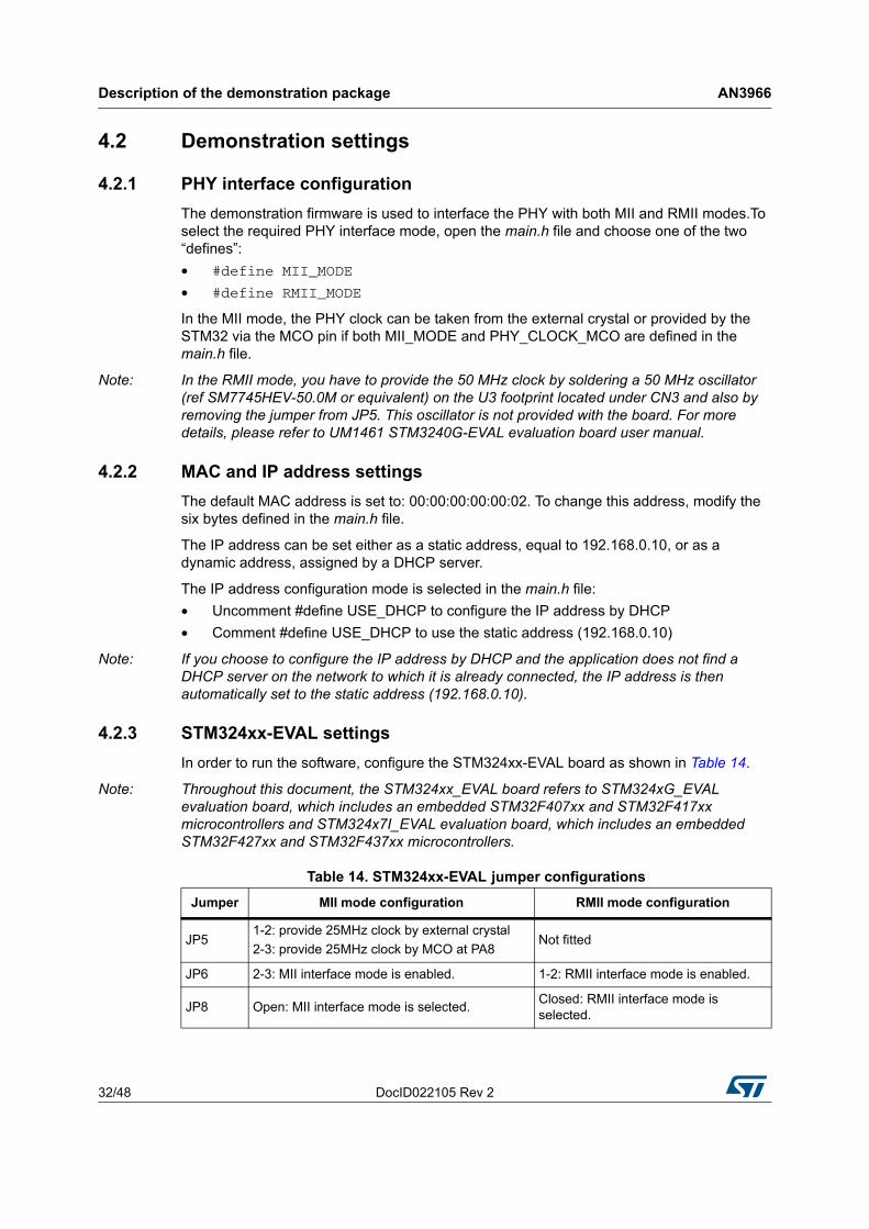
4.2.3 STM324xx-EVAL settingsIn order to run the software, configure the STM324xx-EVAL board as shown in Table 14.
Note: Throughout this document, the STM324xx_EVAL board refers to STM324xG_EVAL evaluation board, which includes an embedded STM32F407xx and STM32F417xx microcontrollers and STM324x7I_EVAL evaluation board, which includes an embedded STM32F427xx and STM32F437xx microcontrollers.
Table 14. STM324xx-EVAL jumper configurationsJumper MII mode configuration RMII mode configuration
JP51-2: provide 25MHz clock by external crystal 2-3: provide 25MHz clock by MCO at PA8
Not fitted
JP6 2-3: MII interface mode is enabled. 1-2: RMII interface mode is enabled.
JP8 Open: MII interface mode is selected. Closed: RMII interface mode is selected.
DocID022105 Rev 2 33/48
AN3966 Using the demos
47
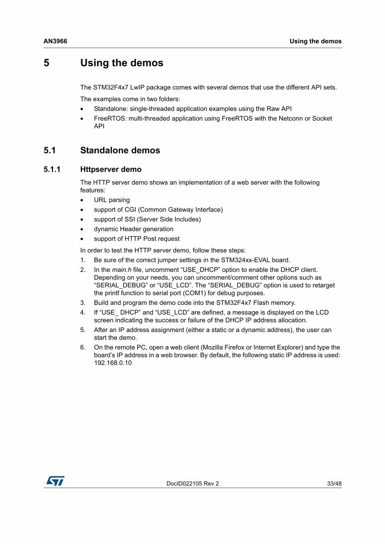
5 Using the demos
The STM32F4x7 LwIP package comes with several demos that use the different API sets.
The examples come in two folders:• Standalone: single-threaded application examples using the Raw API• FreeRTOS: multi-threaded application using FreeRTOS with the Netconn or Socket
API
5.1 Standalone demos
5.1.1 Httpserver demoThe HTTP server demo shows an implementation of a web server with the following features:• URL parsing• support of CGI (Common Gateway Interface) • support of SSI (Server Side Includes)• dynamic Header generation• support of HTTP Post request
In order to test the HTTP server demo, follow these steps:1. Be sure of the correct jumper settings in the STM324xx-EVAL board.2. In the main.h file, uncomment “USE_DHCP” option to enable the DHCP client.
Depending on your needs, you can uncomment/comment other options such as “SERIAL_DEBUG” or “USE_LCD”. The “SERIAL_DEBUG” option is used to retarget the printf function to serial port (COM1) for debug purposes.
3. Build and program the demo code into the STM32F4x7 Flash memory. 4. If “USE_ DHCP” and “USE_LCD” are defined, a message is displayed on the LCD
screen indicating the success or failure of the DHCP IP address allocation.5. After an IP address assignment (either a static or a dynamic address), the user can
start the demo.6. On the remote PC, open a web client (Mozilla Firefox or Internet Explorer) and type the
board’s IP address in a web browser. By default, the following static IP address is used: 192.168.0.10

Using the demos AN3966
34/48 DocID022105 Rev 2
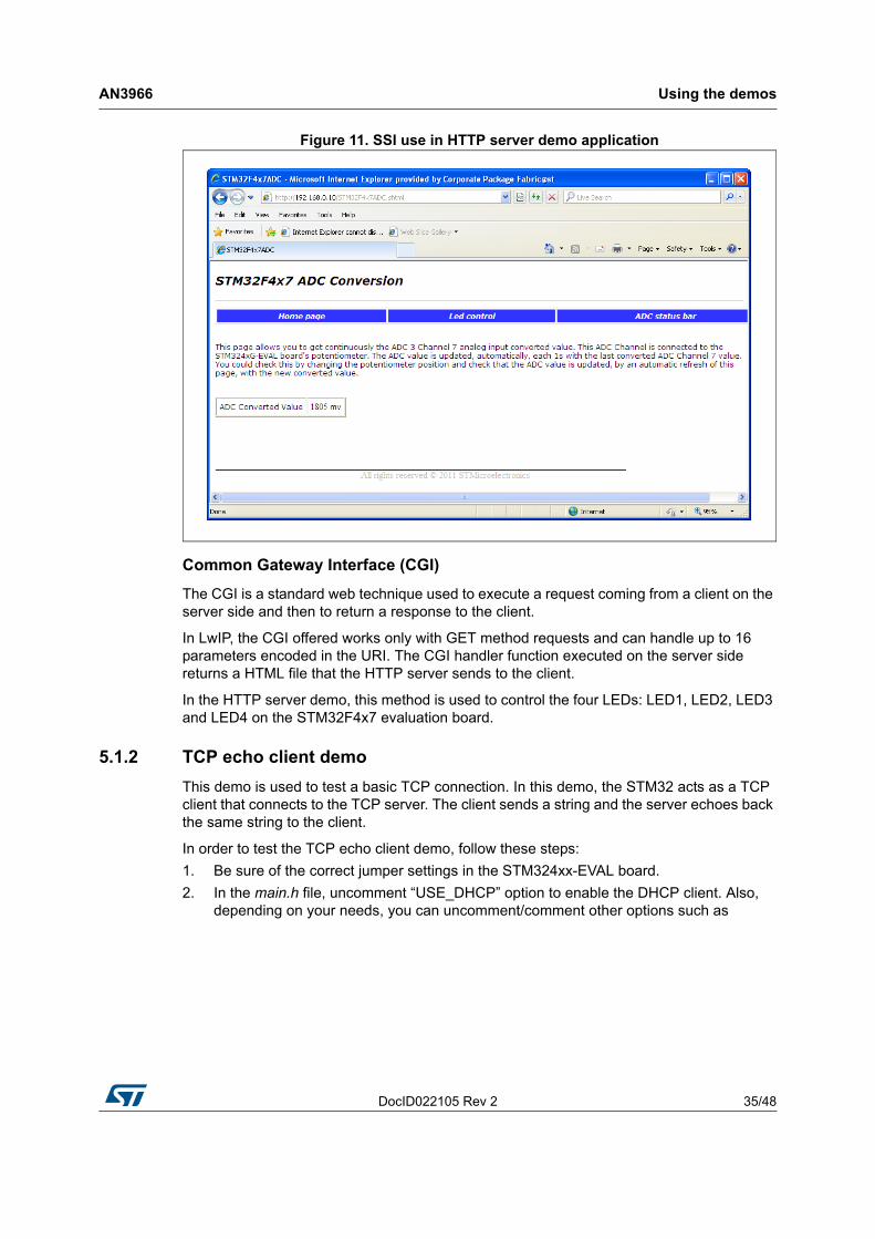
Figure 10. Home page of the HTTP server demo
Server Side Includes (SSI)
SSI is a method used to dynamically include dynamic data in HTML code.
This is done by placing a specific tag inside the HTML code of the web page. The tag should have the following format: <!--#tag-->
For the ADC conversion page, the following tag is used inside the HTML code: <!--#t-->
When there is a request for the ADC webpage (which has a “.shtml” extension), the server will parse the webpage and when the tag is found, it will be replaced by the ADC conversion value.
DocID022105 Rev 2 35/48
AN3966 Using the demos
47
Figure 11. SSI use in HTTP server demo application
Common Gateway Interface (CGI)
The CGI is a standard web technique used to execute a request coming from a client on the server side and then to return a response to the client.
In LwIP, the CGI offered works only with GET method requests and can handle up to 16 parameters encoded in the URI. The CGI handler function executed on the server side returns a HTML file that the HTTP server sends to the client.
In the HTTP server demo, this method is used to control the four LEDs: LED1, LED2, LED3 and LED4 on the STM32F4x7 evaluation board.
5.1.2 TCP echo client demoThis demo is used to test a basic TCP connection. In this demo, the STM32 acts as a TCP client that connects to the TCP server. The client sends a string and the server echoes back the same string to the client.
In order to test the TCP echo client demo, follow these steps:1. Be sure of the correct jumper settings in the STM324xx-EVAL board.2. In the main.h file, uncomment “USE_DHCP” option to enable the DHCP client. Also,
depending on your needs, you can uncomment/comment other options such as
Using the demos AN3966
36/48 DocID022105 Rev 2
“SERIAL_DEBUG” or “USE_LCD”. The “SERIAL_DEBUG” option enables you to retarget the printf function to serial port (COM1) for debug purposes.
3. Build and program the demo code into the STM32F4x7 Flash memory. 4. If “USE_ DHCP” and “USE_LCD” are defined, a message is displayed on the LCD
screen indicating the success or failure of the DHCP IP address allocation.5. After the IP address assignment (either a static or a dynamic address), the user can
start the demo.6. On the remote PC, open a command prompt window. (In Windows, select Start > All
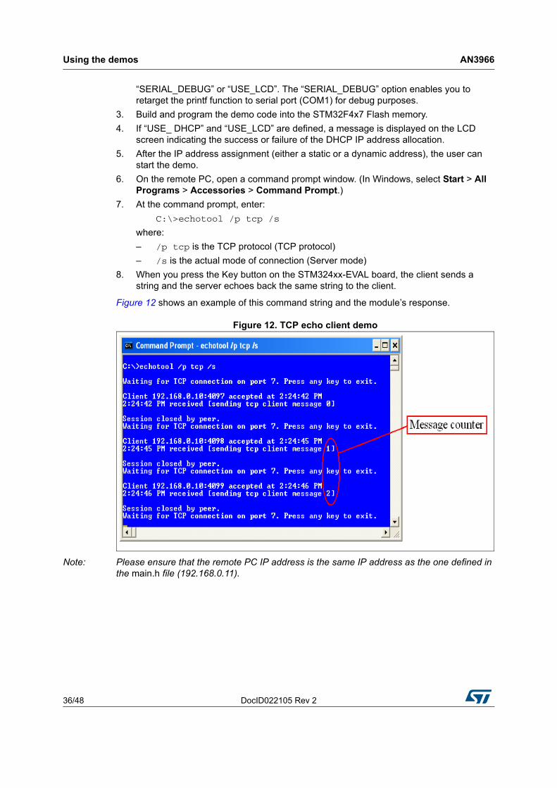
Programs > Accessories > Command Prompt.)7. At the command prompt, enter:
C:\>echotool /p tcp /s
where:– /p tcp is the TCP protocol (TCP protocol)– /s is the actual mode of connection (Server mode)
8. When you press the Key button on the STM324xx-EVAL board, the client sends a string and the server echoes back the same string to the client.
Figure 12 shows an example of this command string and the module’s response.
Figure 12. TCP echo client demo
Note: Please ensure that the remote PC IP address is the same IP address as the one defined in the main.h file (192.168.0.11).
DocID022105 Rev 2 37/48
AN3966 Using the demos
47
5.1.3 TCP echo server demoThis demo is used to test a basic TCP connection. In this demo, the STM32 acts as a TCP server that waits for client requests. It simply echoes back whatever is sent.
In order to test the TCP echo server demo, follow these steps:1. Be sure of the correct jumper settings in the STM324xx-EVAL board.2. In the main.h file, uncomment “USE_DHCP” option to enable the DHCP client. Also
depending on your needs, you can uncomment/comment other options such as “SERIAL_DEBUG” or “USE_LCD”. The “SERIAL_DEBUG” option is used to retarget the printf function to serial port (COM1) for debug purposes.
3. Build and program the demo code into the STM32F4x7 Flash memory. 4. If “USE_ DHCP” and “USE_LCD” are defined, a message is displayed on the LCD
screen indicating the success or failure of the DHCP IP address allocation.5. After an IP address assignment (either a static or a dynamic address), the user can
start the demo. 6. On the remote PC, open a command prompt window. (In Windows, select Start > All
Programs > Accessories > Command Prompt.)7. At the command prompt, enter:
C:\>echotool IP_address /p tcp /r 7 /n 15 /t 2 /d Testing LwIP TCP echo server
where:– IP_address is the actual board’s IP address. By default, the following static IP
address is used: 192.168.0.10– /p tcp is the protocol (TCP protocol)– /r is the actual remote port on the echo server (echo port)– /n is the number of echo requests (for example, 15)– /t is the connection timeout in seconds (for example, 2)– /d is the message to be sent for echo (for example, “Testing LwIP TCP echo
server”)

Using the demos AN3966
38/48 DocID022105 Rev 2
Figure 13 shows an example of this command string and the module’s response.
Figure 13. TCP echo server demo
Note: Statistics providing the number of received and corrupted packets are given at the end of the test.
DocID022105 Rev 2 39/48
AN3966 Using the demos
47
5.1.4 UDP echo client demoThis demo is used to test a basic UDP echo connection. In this demo, the STM32 acts as a UDP client that connects to a UDP server.
In order to test the UDP echo client demo, follow these steps:1. Be sure of the correct jumper settings in the STM324xx-EVAL board.2. In the main.h file, uncomment “USE_DHCP” option to enable the DHCP client. Also,
depending on your needs, you can uncomment/comment other options such as “SERIAL_DEBUG” or “USE_LCD”. The “SERIAL_DEBUG” option is used to retarget the printf function to serial port (COM1) for debug purposes.
3. Build and program the demo code into the STM32F4x7 Flash memory. 4. If “USE_ DHCP” and “USE_LCD” are defined, a message is displayed on the LCD
screen indicating the success or failure of the DHCP IP address allocation.5. After the IP address assignment (either a static or a dynamic address), the user can
start the demo.6. On the remote PC, open a command prompt window. (In Windows, select Start > All
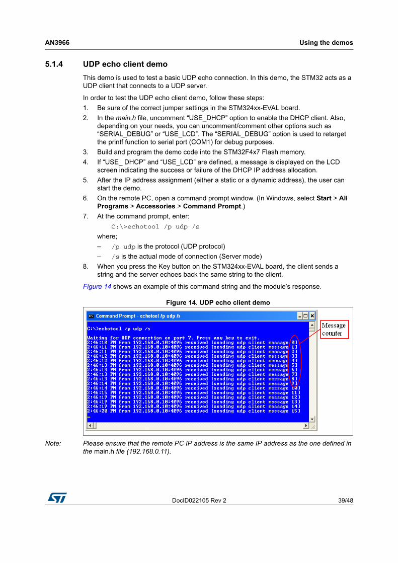
Programs > Accessories > Command Prompt.)7. At the command prompt, enter:
C:\>echotool /p udp /s
where;– /p udp is the protocol (UDP protocol)– /s is the actual mode of connection (Server mode)
8. When you press the Key button on the STM324xx-EVAL board, the client sends a string and the server echoes back the same string to the client.
Figure 14 shows an example of this command string and the module’s response.
Figure 14. UDP echo client demo
Note: Please ensure that the remote PC IP address is the same IP address as the one defined in the main.h file (192.168.0.11).

Using the demos AN3966
40/48 DocID022105 Rev 2
5.1.5 UDP echo server demoThis demo is used to test a basic UDP connection. In this demo, the STM32 acts as a UDP server that waits for client requests.
In order to test the UDP echo server demo, follow these steps:1. Be sure of the correct jumper settings in the STM324xx-EVAL board.2. In the main.h file, uncomment “USE_DHCP” option to enable the DHCP client. Also,
depending on your needs, you can uncomment/comment other options such as “SERIAL_DEBUG” or “USE_LCD”. The “SERIAL_DEBUG” option is used to retarget the printf function to serial port (COM1) for debug purposes.
3. Build and program the demo code into the STM32F4x7 Flash memory. 4. If “USE_ DHCP” and “USE_LCD” are defined, a message is displayed on the LCD
screen indicating the success or failure of the DHCP IP address allocation.5. After the IP address assignment (either a static or a dynamic address), the user can
start the demo.6. On the remote PC, open a command prompt window. (In Windows, select Start > All
Programs > Accessories > Command Prompt.)7. At the command prompt, enter:
C:\>echotool IP_address /p udp /r 7 l/ 7 /n 15 /t 2 /d Testing LwIP UDP echo server
where:– IP_address is the actual board’s IP address. By default, the following static IP
address is used: 192.168.0.10– /p udp is the protocol (UDP protocol)– /r is the actual remote port on the echo server (echo port)– /l is the actual local port for the client (echo port)– /n is the number of echo requests (for example, 15)– /t is the connection timeout in seconds (for example, 2)– /d is the message to be sent for echo (for example, “Testing LwIP UDP echo
server”)

DocID022105 Rev 2 41/48
AN3966 Using the demos
47
Figure 15 shows an example of this command string and the module’s response.
Figure 15. UDP echo server demon
Note: Statistics providing the number of received and corrupted packets are given at the end of the test.
5.1.6 TFTP server demo The TFTP server is a file transfer application that needs a remote TFTP client. The files are transferred to and from the microSD card located on the STM324xx-EVAL board.
The TFTP server waits for a request from a remote TFTP client. The STM324xx-EVAL board must be connected through a remote PC to download or upload a file. To do this, a TFTP client must be installed on the remote PC. This can be done by using the tftpd32 tool, which can be found at http://tftpd32.jounin.net
In order to test the tftpserver demo, follow these steps:1. Be sure of the correct jumper settings in the STM324xx-EVAL board.2. In the main.h file, uncomment “USE_DHCP” option to enable the DHCP client. Also,
depending on your needs, you can uncomment/comment other options such as “SERIAL_DEBUG” or “USE_LCD”. The “SERIAL_DEBUG” option is used to retarget the printf function to serial port (COM1) for debug purposes.
3. Build and program the demo code into the STM32F4x7 Flash memory. 4. If “USE_ DHCP” and “USE_LCD” are defined, a message is displayed on the LCD
screen indicating the success or failure of the DHCP IP address allocation.5. After the IP address assignment (either a static or a dynamic address), the user can
start the demo.6. On the remote PC, open the TFTP client (for example, TFTPD32), and configure the
TFTP server address (host address in TFTPD32).7. Start transferring files to and from the microSD card located on the STM324xx-EVAL
board.

Using the demos AN3966
42/48 DocID022105 Rev 2
Figure 16 gives an overview of the tftpd32 tool.
Figure 16. TFTP tool (tftpd32)
Note: Make sure that the microSD™ card is plugged into the dedicated connector (CN6) prior to downloading/uploading a file from/to the STM324xx-EVAL board.
5.2 FreeRTOS demos
5.2.1 HTTP server netconn demoThe HTTP server netconn demo shows an implementation of a web server application based on the netconn API. This demo is used to connect to the STM324xx-EVAL board from the web browser and to load HTML pages.
This demo has two HTML pages. The first one contains general information about STM32F4x7 microcontrollers, the demonstration package and the LwIP stack. The second one contains the list of running tasks and their status. This page is automatically updated every second.
In order to test the HTTP server netconn demo, follow these steps:1. Be sure of the correct jumper settings in the STM324xx-EVAL board.2. In the main.h file, uncomment “USE_DHCP” option to enable the DHCP client. Also,
depending on your needs, you can uncomment/comment other options such as
DocID022105 Rev 2 43/48
AN3966 Using the demos
47
“SERIAL_DEBUG” or “USE_LCD”. The “SERIAL_DEBUG” option is used to retarget the printf function to serial port (COM1) for debug purposes.
3. Build and program the demo code into the STM32F4x7 Flash memory. 4. If “USE_DHCP” and “USE_LCD” are defined, a message is displayed on the LCD
screen indicating the success or failure of the DHCP IP address allocation.5. After the IP address assignment (either a static or a dynamic address), the user can
start the demo.6. On the remote PC, open a web client (Mozilla Firefox or Internet Explorer) and type the
board’s IP address in a web browser. By default, the following static IP address is used: 192.168.0.10.
5.2.2 HTTP server socket demo The HTTP server socket demo shows an implementation of a web server application based on the socket API. To test this demo, refer to Section 5.2.1: HTTP server netconn demo.
5.2.3 UDP TCP echo server netconn demoThis demo provides the echo service application on both TCP and UDP protocols:• To test the UDP TCP echo server netconn demo in TCP server mode, refer to
Section 5.1.3: TCP echo server demo.• To test the UDP TCP echo server netconn demo in UDP server mode, refer to
Section 5.1.5: UDP echo server demo.

Footprint information AN3966
44/48 DocID022105 Rev 2
6 Footprint information
6.1 HTTP server demoTable 15 provides the HTTP server demonstration footprint, calculated with the following configuration:• 12 buffers of 512 bytes constitute the LwIP pool of buffers. These parameters are
defined in the LwIPopts.h file by PBUF_POOL_SIZE and PBUF_POOL_BUFSIZE.• 10 Kbytes dedicated to the LwIP's heap and defined in the LwIPopts.h file by
MEM_SIZE.• 6 buffers of 1520 bytes dedicated to the Ethernet driver and defined in the
STM32F4x7_eth_conf.h file.
Note: These values are provided for demonstration purposes only. When porting the current package for use with your application, these parameters should be adjusted to your needs.
Note: The software is compiled using IAR EWARM v6.50.1, with a high speed code optimization.
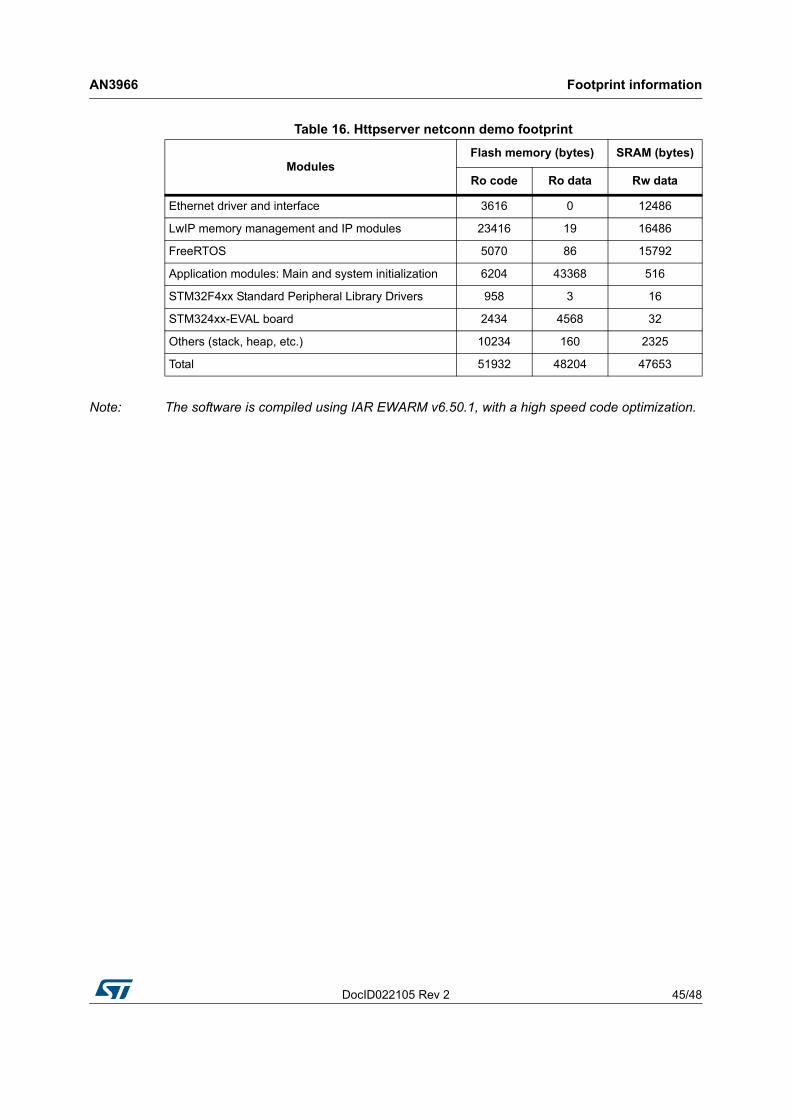
6.2 HTTP server netconn demoTable 16 provides the HTTP server demonstration footprint, calculated with the following configuration:• 12 buffers of 512 bytes constitute the LwIP pool of buffers. These parameters are
defined in the LwIPopts.h file by PBUF_POOL_SIZE and PBUF_POOL_BUFSIZE.• 5 Kbytes dedicated to the LwIP's heap and defined in the LwIPopts.h file by MEM_SIZE.• 8 buffers of 1520 bytes dedicated to the Ethernet driver and defined in the
STM32F4x7_eth_conf.h file.
Note: These values are provided for demonstration purposes only. When porting the current package for use with your application, these parameters should be adjusted to your needs.
Table 15. HTTP server demo footprint
ModulesFlash memory (bytes) SRAM (bytes)
Ro code Ro data Rw data
Ethernet driver and interface 2828 0 9360
LwIP memory management and IP modules 18634 20 19978
Application modules: Main and system initialization 6988 52385 1581
STM32F4xx Standard Peripheral Library Drivers 1270 5 16
STM324xx-EVAL board 2450 4568 32
Others (stack, heap, etc.) 8456 113 1803
Total 40626 57 091 32 770
DocID022105 Rev 2 45/48
AN3966 Footprint information
47
Note: The software is compiled using IAR EWARM v6.50.1, with a high speed code optimization.
Table 16. Httpserver netconn demo footprint
ModulesFlash memory (bytes) SRAM (bytes)
Ro code Ro data Rw data
Ethernet driver and interface 3616 0 12486
LwIP memory management and IP modules 23416 19 16486
FreeRTOS 5070 86 15792
Application modules: Main and system initialization 6204 43368 516
STM32F4xx Standard Peripheral Library Drivers 958 3 16
STM324xx-EVAL board 2434 4568 32
Others (stack, heap, etc.) 10234 160 2325
Total 51932 48204 47653

Conclusion AN3966
46/48 DocID022105 Rev 2
7 Conclusion
The aim of this application note is to show the use of the LwIP TCP/IP stack with the STM32F4x7 family. This open source stack offers the services of a full-scale TCP/IP stack while keeping relatively low RAM/ROM usage.
The application note also shows two approaches for developing TCP/IP applications, either in a Standalone mode, or using a real-time operating system (RTOS) for multi-threaded operations.
DocID022105 Rev 2 47/48
AN3966 Revision history
47
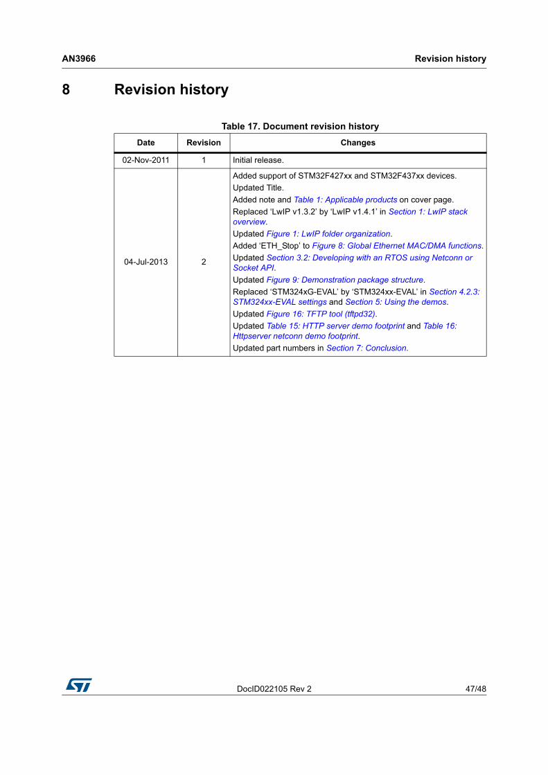
8 Revision history
Table 17. Document revision historyDate Revision Changes
02-Nov-2011 1 Initial release.
04-Jul-2013 2
Added support of STM32F427xx and STM32F437xx devices.Updated Title.Added note and Table 1: Applicable products on cover page.Replaced ‘LwIP v1.3.2’ by ‘LwIP v1.4.1’ in Section 1: LwIP stack overview.Updated Figure 1: LwIP folder organization.Added ‘ETH_Stop’ to Figure 8: Global Ethernet MAC/DMA functions.Updated Section 3.2: Developing with an RTOS using Netconn or Socket API.Updated Figure 9: Demonstration package structure.Replaced ‘STM324xG-EVAL’ by ‘STM324xx-EVAL’ in Section 4.2.3: STM324xx-EVAL settings and Section 5: Using the demos.Updated Figure 16: TFTP tool (tftpd32).Updated Table 15: HTTP server demo footprint and Table 16: Httpserver netconn demo footprint.Updated part numbers in Section 7: Conclusion.

AN3966
48/48 DocID022105 Rev 2
Please Read Carefully:
Information in this document is provided solely in connection with ST products. STMicroelectronics NV and its subsidiaries (“ST”) reserve theright to make changes, corrections, modifications or improvements, to this document, and the products and services described herein at anytime, without notice.
All ST products are sold pursuant to ST’s terms and conditions of sale.
Purchasers are solely responsible for the choice, selection and use of the ST products and services described herein, and ST assumes noliability whatsoever relating to the choice, selection or use of the ST products and services described herein.
No license, express or implied, by estoppel or otherwise, to any intellectual property rights is granted under this document. If any part of thisdocument refers to any third party products or services it shall not be deemed a license grant by ST for the use of such third party productsor services, or any intellectual property contained therein or considered as a warranty covering the use in any manner whatsoever of suchthird party products or services or any intellectual property contained therein.
UNLESS OTHERWISE SET FORTH IN ST’S TERMS AND CONDITIONS OF SALE ST DISCLAIMS ANY EXPRESS OR IMPLIEDWARRANTY WITH RESPECT TO THE USE AND/OR SALE OF ST PRODUCTS INCLUDING WITHOUT LIMITATION IMPLIEDWARRANTIES OF MERCHANTABILITY, FITNESS FOR A PARTICULAR PURPOSE (AND THEIR EQUIVALENTS UNDER THE LAWSOF ANY JURISDICTION), OR INFRINGEMENT OF ANY PATENT, COPYRIGHT OR OTHER INTELLECTUAL PROPERTY RIGHT.
ST PRODUCTS ARE NOT AUTHORIZED FOR USE IN WEAPONS. NOR ARE ST PRODUCTS DESIGNED OR AUTHORIZED FOR USEIN: (A) SAFETY CRITICAL APPLICATIONS SUCH AS LIFE SUPPORTING, ACTIVE IMPLANTED DEVICES OR SYSTEMS WITHPRODUCT FUNCTIONAL SAFETY REQUIREMENTS; (B) AERONAUTIC APPLICATIONS; (C) AUTOMOTIVE APPLICATIONS ORENVIRONMENTS, AND/OR (D) AEROSPACE APPLICATIONS OR ENVIRONMENTS. WHERE ST PRODUCTS ARE NOT DESIGNEDFOR SUCH USE, THE PURCHASER SHALL USE PRODUCTS AT PURCHASER’S SOLE RISK, EVEN IF ST HAS BEEN INFORMED INWRITING OF SUCH USAGE, UNLESS A PRODUCT IS EXPRESSLY DESIGNATED BY ST AS BEING INTENDED FOR “AUTOMOTIVE,AUTOMOTIVE SAFETY OR MEDICAL” INDUSTRY DOMAINS ACCORDING TO ST PRODUCT DESIGN SPECIFICATIONS.PRODUCTS FORMALLY ESCC, QML OR JAN QUALIFIED ARE DEEMED SUITABLE FOR USE IN AEROSPACE BY THECORRESPONDING GOVERNMENTAL AGENCY.
Resale of ST products with provisions different from the statements and/or technical features set forth in this document shall immediately voidany warranty granted by ST for the ST product or service described herein and shall not create or extend in any manner whatsoever, anyliability of ST.
ST and the ST logo are trademarks or registered trademarks of ST in various countries.Information in this document supersedes and replaces all information previously supplied.
The ST logo is a registered trademark of STMicroelectronics. All other names are the property of their respective owners.
© 2013 STMicroelectronics - All rights reserved
STMicroelectronics group of companies
Australia - Belgium - Brazil - Canada - China - Czech Republic - Finland - France - Germany - Hong Kong - India - Israel - Italy - Japan - Malaysia - Malta - Morocco - Philippines - Singapore - Spain - Sweden - Switzerland - United Kingdom - United States of America
www.st.com