an_344 ft51a dfu_sample -...
TRANSCRIPT
Use of FTDI devices in life support and/or safety applications is entirely at the user’s risk, and the user agrees to defend, indemnify and hold FTDI harmless from any and all damages, claims, suits
or expense resulting from such use.
Future Technology Devices International Limited (FTDI) Unit 1, 2 Seaward Place, Glasgow G41 1HH, United Kingdom Tel.: +44 (0) 141 429 2777 Fax: + 44 (0) 141 429 2758
Web Site: http://ftdichip.com Copyright © 2015 Future Technology Devices International Limited
Application Note
AN_344
FT51A DFU Sample
Version 1.0
Issue Date: 2015-12-21
This document provides a guide for using the FT51A development environment to incorporate DFU (Device Firmware Upgrade) support in firmware.
Application Note
AN_344 FT51A DFU Sample Version 1.0
Document Reference No.: FT_001122 Clearance No.: FTDI# 481
2 Product Page Document Feedback Copyright © 2015 Future Technology Devices International Limited
Table of Contents
1 Introduction .............................................................. 4
1.1 Overview ............................................................................. 4
1.2 Features .............................................................................. 4
1.3 Limitations .......................................................................... 4
1.4 Scope .................................................................................. 4
2 DFU Overview ............................................................ 5
2.1 DFU Library Overview .......................................................... 5
2.2 Firmware Overview ............................................................. 6
2.2.1 Run-Time Mode .............................................................................................. 6
2.2.2 DFU Mode ...................................................................................................... 7
2.2.1 FT51 Libraries ................................................................................................ 7
2.3 Host PC Application Overview ............................................. 7
3 DFU Firmware ............................................................ 9
3.1 USB Descriptors .................................................................. 9
3.1.1 Run-Time Descriptors ...................................................................................... 9
3.1.2 DFU Descriptors ........................................................................................... 11
3.1.3 Descriptor Selection ...................................................................................... 13
3.2 USB Class Requests ........................................................... 14
3.3 USB Reset Handler ............................................................ 15
3.4 Timer ................................................................................. 16
3.5 Device Detach-Attach ........................................................ 16
4 DFU Application ....................................................... 17
4.1 libusb-win32 ..................................................................... 17
4.1.1 Installing libusb-win32 Driver ......................................................................... 17
4.2 WinUSB ............................................................................. 17
4.2.1 Installing WinUSB Driver ............................................................................... 17
4.3 Loading Firmware Files ..................................................... 17
4.4 Programming DFU Interfaces ............................................ 17

Application Note
AN_344 FT51A DFU Sample Version 1.0
Document Reference No.: FT_001122 Clearance No.: FTDI# 481
3 Product Page Document Feedback Copyright © 2015 Future Technology Devices International Limited
5 Possible Improvements ........................................... 18
5.1 Obfuscating DFU Commands ............................................. 20
5.2 Adding Manifestation Checks ............................................. 20
5.3 Recovery ........................................................................... 20
5.4 Security ............................................................................. 20
6 Contact Information ................................................ 21
Appendix A – References ............................................. 23
Document References ............................................................... 23
Acronyms and Abbreviations ..................................................... 23
Appendix B – List of Tables & Figures .......................... 24
List of Figures ........................................................................... 24
Appendix C – Revision History ..................................... 25

Application Note
AN_344 FT51A DFU Sample Version 1.0
Document Reference No.: FT_001122 Clearance No.: FTDI# 481
4 Product Page Document Feedback Copyright © 2015 Future Technology Devices International Limited
1 Introduction
This application note documents the FT51A DFU library and provides an example firmware project for the FT51A and host PC application. The host PC application will communicate with the firmware on the FT51A to update the contents of the FT51A MTP Flash. All communication is via the USB interface.
1.1 Overview
The DFU firmware project and host PC application together demonstrate a reusable method for implementing firmware updates to an FT51A device. The FT51A need only be connected to a host PC via the USB interface.
The DFU firmware is added to the normal functional firmware programmed into the FT51A and is
only activated when special commands are sent by the host PC. It can therefore be built-in to any
FT51A firmware and used when required.
An example application would be to allow Field Service Engineers to update firmware on devices embedded in industrial machinery, or end users to apply an update to a device based on an FT51A.
1.2 Features
The DFU library has the following features:
- Open source library layered on FT51A USB Library. - Can be added to existing firmware by adding an interface to the configuration descriptor. - Ability to download firmware from host PC to device.
- User firmware implements the USB requests. This allows non-standard methods to be implemented to add obfuscation.
1.3 Limitations
The DFU library has the following limitations:
- No manifestation stage. The device cannot support manifestation and cannot therefore process a firmware image before programming.
As with most firmware updates, it is imperative that the firmware download is not interrupted either by power interruption or by interrupting the programming application as the data downloaded immediately overwrites the contents of the MTP Flash rendering the existing contents invalid.
A recovery method is to use the FT51A programmer/debugger module and the “FT51prg.exe” tool to re-load valid code to the MTP Flash. Details on this tool can be found in Application Note AN_289 FT51A Programming Guide. The executable and source code for “FT51prg.exe” are available in the FT51A Software Development Kit.
1.4 Scope
The guide is intended for developers who are creating applications, extending FTDI provided applications or implementing example applications for the FT51A.
In the reference of the FT51A, an “application” refers to firmware that runs on the FT51A; “libraries” are source code provided by FTDI to help user’s access specific hardware features of the chip.
The FT51A Tools are currently only available for Microsoft Windows platform and are tested on Windows 7 and Windows 8.1.

Application Note
AN_344 FT51A DFU Sample Version 1.0
Document Reference No.: FT_001122 Clearance No.: FTDI# 481
5 Product Page Document Feedback Copyright © 2015 Future Technology Devices International Limited
2 DFU Overview
The DFU protocol and requirements are documented in the Device Firmware Upgrade 1.1 specification:
http://www.usb.org/developers/docs/devclass_docs/DFU_1.1.pdf
The FT51A implementation is for devices which are capable of downloading and can optionally perform any detach-attach sequence to switch between DFU and run-time modes.
Due to the memory constraints of the FT51A it is not practical to implement manifestation. This
would require storing and validating the firmware before programming the MTP Flash.
2.1 DFU Library Overview
The DFU library uses the FT51A USB library and calls the following functions:
- USB_transfer()
- USB_stall_endpoint()
It is contained in a single source code file “ft51_usb_dfu.c” and has a library header “ft51_usb_dfu.h”.
The DFU Attributes supported by the library, as described in the bmAttributes field of the DFU
Functional Descriptor, are bitWillDetach and bitCanDnload. The bitManifestationTolerant and
bitCanUpload features are not supported.
Calls to the library are made by the firmware when class requests are received for the DFU interface or when a bus state change on the USB is detected.
Additionally there is a timer handler which must be called every millisecond to implement the detach timer described in the specification.
The DFU library implements a state machine to provide the functionality required by the DFU specification. A schematic of the state machine is shown in Figure 2.1. Run-time mode states are
red and DFU mode states are blue.
The “USB Reset” transitions can be either performed by the host resetting the USB or by the device detaching from the USB. If the bitWillDetach attribute is set then the device must perform
detach. If it is not set then the host must reset the USB.

Application Note
AN_344 FT51A DFU Sample Version 1.0
Document Reference No.: FT_001122 Clearance No.: FTDI# 481
6 Product Page Document Feedback Copyright © 2015 Future Technology Devices International Limited
Figure 2.1 DFU States
2.2 Firmware Overview
The firmware is specifically written to allow it to be adapted and easily included in other FT51A projects.
Firmware will initialise and configure the FT51A as normal, setting up the USB device as required. It will however, add some code to the USB standard requests handlers to support the DFU library.
The only libraries required are the FT51A USB library and parts of the FT51A General Config library. If LED indicators are desired then the IOMUX library can be added to configure output pins
for LEDs.
2.2.1 Run-Time Mode
When in run-time mode, the firmware will return a configuration descriptor containing the normal functions of the FT51A firmware plus one additional interface descriptor for the DFU. This is the DFU functional descriptor.
The firmware will decode standard and vendor requests as normal, but check for class requests which are addressed to the DFU interface. If these are found then a function in the DFU library will
be called. From run-time mode the DFU can check the status and state of the DFU state machine and initiate a DFU_DETACH to transition into DFU mode.
appIDLE dfuIDLE
dfuERROR
appDETACH
TIMEOUT
DFU_DETACH request
USB Reset
DFU_DNLOAD request
dfuDNLOAD-IDLE
dfuMANIFEST-WAIT-RESET
DFU_CLRSTATUS request
DFU_DNLOAD end request
DFU_DNLOAD invalid request
dfuMANIFEST-SYNC
dfuDNLOAD-SYNC
DFU_GET_STATUS request
DFU_GET_STATUS request
DFU_DNLOAD request
USB Reset

Application Note
AN_344 FT51A DFU Sample Version 1.0
Document Reference No.: FT_001122 Clearance No.: FTDI# 481
7 Product Page Document Feedback Copyright © 2015 Future Technology Devices International Limited
If the bitWillDetach attribute is not set the DFU_DETACH request will start a timer and continue.
If a USB reset is observed before the timer expires then the DFU state machine will move to DFU mode.
If the bitWillDetach attribute is set the device will detach from the USB using a call to the USB
library. The host will see this as a disconnection and will re-enumerate the device when it reattaches to the USB.
With both methods a function handler for USB reset events will call the DFU library to change from run-time to DFU mode.
2.2.2 DFU Mode
When DFU mode is entered, the normal functions of the firmware are not available and the
firmware will return different device and configuration descriptors. This will have a single interface describing the DFU mode. The device will be re-enumerated by the host and the new device and configuration descriptors read.
Standard USB requests will be handled as normal, but class requests to the DFU interface (this may be a different interface number in DFU mode from the run-time mode) will be passed to the DFU library.
If the bitWillDetach attribute is not set the device will rely on the host performing a USB reset
when programming is finished, otherwise the device will detach from the USB and force the host to re-enumerate the device.
Again, the function handler for USB reset events must also call the DFU library to change from DFU back to run-time mode and resetting the FT51A to run the newly programmed firmware.
2.2.3 FT51A Libraries
The DFU firmware uses the FT51A USB library, DFU library, general config library and the IOMUX
library. The IOMUX library is not used in the example code but is included to allow further functionality to be added.
2.2.4 WinUSB Drivers
The firmware will use WCID (Windows Compatible ID) to tell a Microsoft Windows operating system that is requires WinUSB to be installed for the DFU interface. This is achieved by the firmware responding to a Microsoft defined string descriptor to identify the device as supporting WCID and providing the host PC with a vendor request code for the next stage of WCID.
The second stage tells the host PC which drivers to load for the device by responding to a set of vendor requests with information required.
When this is successfully completed the DFU interface is accessible to host PC applications using the WinUSB API. It is also compatible with libusb for Windows.
Please note that the WinUSB drivers will need to be installed when the device is first connected. They will also need to be installed when the device changes from run-time mode to DFU mode.
Each time the driver is loaded it may go to Windows Update to check for newer drivers.
2.3 Host PC Application Overview
The host PC application recommended is dfu-util. This can be obtained from http://dfu-util.sourceforge.net/
It uses the libusb library to communicate with the device via Microsoft WinUSB drivers.
The dfu-util program is a command line application that programs a binary file onto the device. The FT51A Eclipse plugin has a Post Build step to produce a “.bin” binary file from the IHX (Intel
HeX file) output file using the makebin utility supplied by SDCC.

Application Note
AN_344 FT51A DFU Sample Version 1.0
Document Reference No.: FT_001122 Clearance No.: FTDI# 481
8 Product Page Document Feedback Copyright © 2015 Future Technology Devices International Limited
The format of the dfu-util command line is typically as follows:
dfu-util –D filename.bin
Refer to the documentation for dfu-util for further options.
The first time dfu-util switches the device from run-time to DFU mode it may timeout waiting for Windows to install the WinUSB driver. Re-running dfu-util when this process is complete will re-commence the firmware update correctly.

Application Note
AN_344 FT51A DFU Sample Version 1.0
Document Reference No.: FT_001122 Clearance No.: FTDI# 481
9 Product Page Document Feedback Copyright © 2015 Future Technology Devices International Limited
3 DFU Firmware
The firmware included in the example code demonstrates implementing run-time mode descriptors, DFU mode descriptors, switching from run-time to DFU mode and updating firmware. It has no run-time features; however, these can be added by extending the run-time configuration descriptor and adding code for the features.
The control endpoint max packet size is defined in the header of the firmware code for convenience along with the Product IDs (PIDs) used in the example. The setting of
bMaxPacketSize0 in the device descriptor MUST match the size of the control endpoint max packet size set in the “ep_size” member of the USB_ctx structure when the USB library is initialised.
The following code is used to set the packet sizes for the control endpoint for both the device descriptor and USB initialisation. // USB Endpoint Zero packet size (both must match) #define USB_CONTROL_EP_MAX_PACKET_SIZE 8 #define USB_CONTROL_EP_SIZE USB_EP_SIZE_8
The DFU library does not calculate addresses from the block numbers passed in the DFU_DNLOAD request. The application specifies both the size of the programming block and calculates the address. This increases the flexibility of the library and allows the application to set block sizes and even how addresses are calculated.
The maximum block size for the DFU library is 64 bytes as defined in DFU_MAX_BLOCK_SIZE in
“ft51_usb_dfu.h”. This can be changed to a smaller value by modifying the definition of DFU_BLOCK_SIZE.
#define DFU_BLOCK_SIZE DFU_MAX_BLOCK_SIZE
3.1 USB Descriptors
The DFU firmware stores two sets of device descriptors and configuration descriptors. It stores a
single table of string descriptors as the strings for run-time and DFU modes can be selected by the descriptors as needed from the same table.
The USB class, subclass and protocols along with other general USB definitions are found in the file “ft51_usb.h” library include file.
3.1.1 Run-Time Descriptors
The first set of descriptors is the run-time set. The device descriptor contains the VID and PID for the run-time function.

Application Note
AN_344 FT51A DFU Sample Version 1.0
Document Reference No.: FT_001122 Clearance No.: FTDI# 481
10 Product Page Document Feedback Copyright © 2015 Future Technology Devices International Limited
USB_device_descriptor device_descriptor_runtime = { .bLength = 0x12, .bDescriptorType = 0x01, .bcdUSB = USB_BCD_VERSION_2_0, .bDeviceClass = USB_CLASS_DEVICE, .bDeviceSubClass = USB_SUBCLASS_DEVICE, .bDeviceProtocol = USB_PROTOCOL_DEVICE, .bMaxPacketSize0 = USB_CONTROL_EP_MAX_PACKET_SIZE, .idVendor = USB_VID_FTDI, // 0x0403 (FTDI) .idProduct = DFU_USB_PID_RUNTIME, // 0x0fed .bcdDevice = 0x0101, .iManufacturer = 0x01, // String 1 .iProduct = 0x02, // String 2 .iSerialNumber = 0x03, // String 3 .bNumConfigurations = 0x01 };
The configuration descriptor would normally contain interface descriptors and endpoint descriptors for the run-time function. These are not implemented in this example.
The last interface descriptor, and the only one in this configuration descriptor, is for a DFU
interface that implements no endpoints. All DFU communication is through the control endpoints to the DFU interface.
The USB class of Application Specific allows the subclass to specify that it is a Device Firmware Update (DFU) and the protocol indicates that this is Run-Time mode.
Application Note
AN_344 FT51A DFU Sample Version 1.0
Document Reference No.: FT_001122 Clearance No.: FTDI# 481
11 Product Page Document Feedback Copyright © 2015 Future Technology Devices International Limited
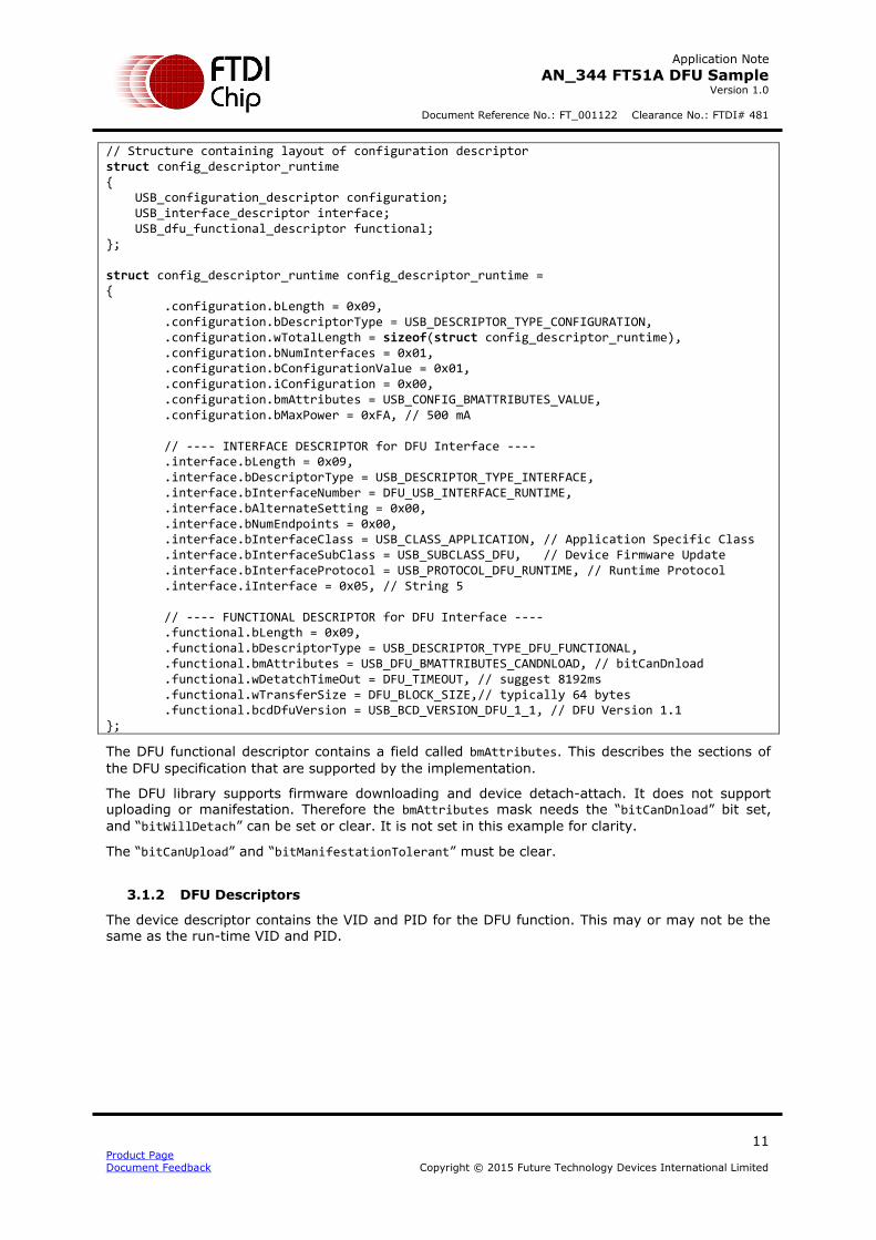
// Structure containing layout of configuration descriptor struct config_descriptor_runtime { USB_configuration_descriptor configuration; USB_interface_descriptor interface; USB_dfu_functional_descriptor functional; }; struct config_descriptor_runtime config_descriptor_runtime = { .configuration.bLength = 0x09, .configuration.bDescriptorType = USB_DESCRIPTOR_TYPE_CONFIGURATION, .configuration.wTotalLength = sizeof(struct config_descriptor_runtime), .configuration.bNumInterfaces = 0x01, .configuration.bConfigurationValue = 0x01, .configuration.iConfiguration = 0x00, .configuration.bmAttributes = USB_CONFIG_BMATTRIBUTES_VALUE, .configuration.bMaxPower = 0xFA, // 500 mA // ---- INTERFACE DESCRIPTOR for DFU Interface ---- .interface.bLength = 0x09, .interface.bDescriptorType = USB_DESCRIPTOR_TYPE_INTERFACE, .interface.bInterfaceNumber = DFU_USB_INTERFACE_RUNTIME, .interface.bAlternateSetting = 0x00, .interface.bNumEndpoints = 0x00, .interface.bInterfaceClass = USB_CLASS_APPLICATION, // Application Specific Class .interface.bInterfaceSubClass = USB_SUBCLASS_DFU, // Device Firmware Update .interface.bInterfaceProtocol = USB_PROTOCOL_DFU_RUNTIME, // Runtime Protocol .interface.iInterface = 0x05, // String 5 // ---- FUNCTIONAL DESCRIPTOR for DFU Interface ---- .functional.bLength = 0x09, .functional.bDescriptorType = USB_DESCRIPTOR_TYPE_DFU_FUNCTIONAL, .functional.bmAttributes = USB_DFU_BMATTRIBUTES_CANDNLOAD, // bitCanDnload .functional.wDetatchTimeOut = DFU_TIMEOUT, // suggest 8192ms .functional.wTransferSize = DFU_BLOCK_SIZE,// typically 64 bytes .functional.bcdDfuVersion = USB_BCD_VERSION_DFU_1_1, // DFU Version 1.1 };
The DFU functional descriptor contains a field called bmAttributes. This describes the sections of
the DFU specification that are supported by the implementation.
The DFU library supports firmware downloading and device detach-attach. It does not support uploading or manifestation. Therefore the bmAttributes mask needs the “bitCanDnload” bit set,
and “bitWillDetach” can be set or clear. It is not set in this example for clarity.
The “bitCanUpload” and “bitManifestationTolerant” must be clear.
3.1.2 DFU Descriptors
The device descriptor contains the VID and PID for the DFU function. This may or may not be the same as the run-time VID and PID.

Application Note
AN_344 FT51A DFU Sample Version 1.0
Document Reference No.: FT_001122 Clearance No.: FTDI# 481
12 Product Page Document Feedback Copyright © 2015 Future Technology Devices International Limited
USB_device_descriptor device_descriptor_dfumode = { .bLength = 0x12, .bDescriptorType = USB_DESCRIPTOR_TYPE_DEVICE, .bcdUSB = USB_BCD_VERSION_2_0, .bDeviceClass = USB_CLASS_DEVICE, .bDeviceSubClass = USB_SUBCLASS_DEVICE, .bDeviceProtocol = USB_PROTOCOL_DEVICE, .bMaxPacketSize0 = USB_CONTROL_EP_MAX_PACKET_SIZE, .idVendor = USB_VID_FTDI, // 0x0403 (FTDI) .idProduct = DFU_USB_PID_DFUMODE, // 0x0fee .bcdDevice = 0x0101, .iManufacturer = 0x01, .iProduct = 0x04, .iSerialNumber = 0x03, .bNumConfigurations = 0x01 };
The configuration descriptor for DFU will contain only an interface descriptor and a functional descriptor for the DFU interface.
The USB class, subclass and protocol indicate that this device is now in DFU mode.
// Structure containing layout of configuration descriptor
struct config_descriptor_dfumode { USB_configuration_descriptor configuration; USB_interface_descriptor interface; USB_dfu_functional_descriptor functional; }; struct config_descriptor_dfumode config_descriptor_dfumode = { .configuration.bLength = 0x09, .configuration.bDescriptorType = USB_DESCRIPTOR_TYPE_CONFIGURATION, .configuration.wTotalLength = sizeof(struct config_descriptor_dfumode), .configuration.bNumInterfaces = 0x01, .configuration.bConfigurationValue = 0x01, .configuration.iConfiguration = 0x00, .configuration.bmAttributes = USB_CONFIG_BMATTRIBUTES_VALUE, .configuration.bMaxPower = 0xFA, // 500 mA // ---- INTERFACE DESCRIPTOR for DFU Interface ---- .interface.bLength = 0x09, .interface.bDescriptorType = USB_DESCRIPTOR_TYPE_INTERFACE, .interface.bInterfaceNumber = DFU_USB_INTERFACE_DFUMODE, .interface.bAlternateSetting = 0x00, .interface.bNumEndpoints = 0x00, .interface.bInterfaceClass = USB_CLASS_APPLICATION, // Application Specific Class .interface.bInterfaceSubClass = USB_SUBCLASS_DFU, // Device Firmware Update .interface.bInterfaceProtocol = USB_PROTOCOL_DFU_DFUMODE, // Runtime Protocol .interface.iInterface = 0x05, // String 5 // ---- FUNCTIONAL DESCRIPTOR for DFU Interface ---- .functional.bLength = 0x09, .functional.bDescriptorType = USB_DESCRIPTOR_TYPE_DFU_FUNCTIONAL, .functional.bmAttributes = USB_DFU_BMATTRIBUTES_CANDNLOAD, // bitCanDnload .functional.wDetatchTimeOut = DFU_TIMEOUT, // suggest 8192ms .functional.wTransferSize = DFU_BLOCK_SIZE,// typically 64 bytes .functional.bcdDfuVersion = USB_BCD_VERSION_DFU_1_1, };

Application Note
AN_344 FT51A DFU Sample Version 1.0
Document Reference No.: FT_001122 Clearance No.: FTDI# 481
13 Product Page Document Feedback Copyright © 2015 Future Technology Devices International Limited
The same bmAttributes mask must appear for the DFU functional descriptor in both run-time and
DFU modes.
3.1.3 Descriptor Selection
The standard request handler for GET_DESCRIPTOR requests needs to select the run time or DFU
mode descriptors. The firmware is responsible for ensuring the correct descriptors are returned to the host PC.
Determining if the firmware is in run-time or DFU mode is achieved by calling the dfu_is_runtime() function from the DFU library.
A non-zero response will select the run-time mode descriptors and a zero response, the DFU mode descriptors.
FT51_STATUS standard_req_get_descriptor(USB_device_request *req) { uint8_t *src = NULL; uint16_t length = req->wLength; uint8_t hValue = req->wValue >> 8; uint8_t lValue = req->wValue & 0x00ff; uint8_t i, slen; switch (hValue) { case USB_DESCRIPTOR_TYPE_DEVICE: if (dfu_is_runtime()) { src = (char *)&device_descriptor_runtime; } else { src = (char *)&device_descriptor_dfumode; } if (length > sizeof(USB_device_descriptor)) // too many bytes requested length = sizeof(USB_device_descriptor); // Entire structure. break; case USB_DESCRIPTOR_TYPE_CONFIGURATION: if (dfu_is_runtime()) { src = (char *)&config_descriptor_runtime; if (length > sizeof(config_descriptor_runtime)) // too many bytes requested length = sizeof(config_descriptor_runtime); // Entire structure. } else { src = (char *)&config_descriptor_dfumode; if (length > sizeof(config_descriptor_dfumode)) // too many bytes requested length = sizeof(config_descriptor_dfumode); // Entire structure. } break;
The FT51A USB library will return the structure pointed to by the standard_req_get_descriptor()
function.
Note that string descriptor selection is not shown in this code sample. It does not depend on the
selection of run-time or DFU modes.

Application Note
AN_344 FT51A DFU Sample Version 1.0
Document Reference No.: FT_001122 Clearance No.: FTDI# 481
14 Product Page Document Feedback Copyright © 2015 Future Technology Devices International Limited
3.2 USB Class Requests
The firmware is responsible for handling USB class requests. It must determine if the firmware is in run-time or DFU mode and whether a request has been directed to the DFU interface. This must not interfere with other class requests that may be decoded in the firmware.
The first check is that the class request is aimed at an interface:
FT51_STATUS class_req_cb(USB_device_request *req) { FT51_STATUS status = FT51_FAILED; uint8_t interface = LSB(req->wIndex) & 0x0F; // For DFU requests ensure the recipient is an interface... if ((req->bmRequestType & USB_BMREQUESTTYPE_RECIPIENT_MASK) == USB_BMREQUESTTYPE_RECIPIENT_INTERFACE) {
If this is correct then the firmware must check if it is in run-time or DFU mode before checking the interface number. The interface number for the DFU mode may differ from that of the run-time mode.
if (dfu_is_runtime()) { if ((interface == DFU_USB_INTERFACE_RUNTIME)) { switch (req->bRequest) { case USB_CLASS_REQUEST_DETACH: dfu_class_req_detach(req->wValue); // Only uncomment if bitWillDetach is set in bmAttributes //usb_detach_attach(); status = FT51_OK; break; case USB_CLASS_REQUEST_GETSTATUS: dfu_class_req_getstatus(); status = FT51_OK; break; case USB_CLASS_REQUEST_GETSTATE: dfu_class_req_getstate(); status = FT51_OK; break; } } }
For run-time mode, only the DFU_DETACH, DFU_GETSTATUS and DFU_GETSTATE requests are valid. All other requests will fail and stall the control endpoint.
The example shows that the DFU_DETACH request will not perform a detach as “bitWillDetach” is
not set in the DFU functional descriptor.
If it is not in run-time mode then a different set of requests are valid.

Application Note
AN_344 FT51A DFU Sample Version 1.0
Document Reference No.: FT_001122 Clearance No.: FTDI# 481
15 Product Page Document Feedback Copyright © 2015 Future Technology Devices International Limited
else { if (interface == DFU_USB_INTERFACE_DFUMODE) { switch (req->bRequest) { case USB_CLASS_REQUEST_DNLOAD: dfu_class_req_download(req->wValue * DFU_MAX_BLOCK_SIZE, req->wLength); status = FT51_OK; break; case USB_CLASS_REQUEST_GETSTATUS: dfu_class_req_getstatus(); if (dfu_is_wait_reset()) { // Only uncomment if bitWillDetach is set in bmAttributes //usb_detach_attach(); } status = FT51_OK; break; case USB_CLASS_REQUEST_GETSTATE: dfu_class_req_getstate(); status = FT51_OK; break; case USB_CLASS_REQUEST_CLRSTATUS: dfu_class_req_clrstatus(); status = FT51_OK; break; case USB_CLASS_REQUEST_ABORT: dfu_class_req_abort(); status = FT51_OK; break; default: case USB_CLASS_REQUEST_UPLOAD: // Unknown or unsupported request. break; } } } } return status; }
In this mode, the DFU_DNLOAD, DFU_GETSTATUS, DFU_CLRSTATUS, DFU_GETSTATE and DFU_ABORT requests are valid. DFU_UPLOAD is specifically checked for and disallowed although ignoring it would have the same effect.
Again the device will not perform any detach as “bitWillDetach” is not set in the DFU functional
descriptor. The DFU_GETSTATUS request is the trigger for a detach-attach sequence when it is
set.
3.3 USB Reset Handler
Transitions from the appDETACH state to the dfuIDLE state and from dfuMANIFEST-WAIT-RESET state to appIDLE are controlled by the USB reset handler function. This is set by the “reset”
member of the USB_ctx structure when the USB library is initialised.
When the reset occurs the dfu_reset() function should be called. If the new firmware which has
been downloaded is to be run then the function will return a non-zero value. If no further action is required then it will return zero.

Application Note
AN_344 FT51A DFU Sample Version 1.0
Document Reference No.: FT_001122 Clearance No.: FTDI# 481
16 Product Page Document Feedback Copyright © 2015 Future Technology Devices International Limited
void reset_cb(uint8_t status) { (void) status; USB_set_state(DEFAULT); if (dfu_reset()) { device_revert(); } }
In this way, when the dfuMANIFEST-WAIT-RESET state is reached the application will wait until a USB bus reset from the host (or a disconnect event) before loading and running the new
application from MTP Flash.
A reset occurring when in appDETACH state will move the DFU state to dfuIDLE. This would be
noticed the next time the firmware calls dfu_is_runtime().
3.4 Timer
The DFU needs a millisecond timer to accurately return to the appIDLE state from the appDETACH state. The dfu_timer() function in the DFU library should be called every millisecond to enable
this.
void detach_interrupt(const uint8_t flags) { (void)flags; // Flags not currently used // The DFU detach timer must be called once per millisecond dfu_timer(); // Reload the timer TH0 = MSB(MICROSECONDS_TO_TIMER_TICKS(1000)); TL0 = LSB(MICROSECONDS_TO_TIMER_TICKS(1000)); } void detach_timer_initialise(void) { // Register our own handler for interrupts from Timer 0 interrupts_register(detach_interrupt, interrupts_timer0); // Timer0 is controlled by TMOD bits 0 to 3, and TCON bits 4 to 5. TMOD &= 0xF0; // Clear Timer0 bits TMOD |= 0x01; // Put Timer0 in mode 1 (16 bit) // Set the count-up value so that it rolls over to 0 after 1 millisecond. TH0 = MSB(MICROSECONDS_TO_TIMER_TICKS(1000)); TL0 = LSB(MICROSECONDS_TO_TIMER_TICKS(1000)); TCON &= 0xCF; // Clear Timer0's Overflow and Run flags TCON |= 0x10; // Start Timer0 (set its Run flag) }
3.5 Device Detach-Attach
A function is provided that will detach and then reattach the device from the USB. This is only required if “bitWillDetach” is set in the DFU functional descriptor.

Application Note
AN_344 FT51A DFU Sample Version 1.0
Document Reference No.: FT_001122 Clearance No.: FTDI# 481
17 Product Page Document Feedback Copyright © 2015 Future Technology Devices International Limited
void usb_detach_attach(void) { // Short delay ms_timer = 10; while (ms_timer > 0); // Disable USB device to force an reset USB_finalise(); ms_timer = 10; while (ms_timer > 0); // Start the USB device. usb_setup(); }

Application Note
AN_344 FT51A DFU Sample Version 1.0
Document Reference No.: FT_001122 Clearance No.: FTDI# 481
18 Product Page Document Feedback Copyright © 2015 Future Technology Devices International Limited
4 WCID Selection
The Windows Compatible ID (WCID) method is used to select the WinUSB driver for the DFU interface.
4.1 WCID String Descriptor
The first step is to respond to a USB String Descriptor request for string number 0xEE with an application specific vendor request code to use for the rest of the WCID process.
This firmware defines the vendor request code to be 0xf1. This can be any value from 0x00 to 0xff.
#define WCID_VENDOR_REQUEST_CODE 0xF1
A macro is defined in ft51_usb.h to craft a Microsoft WCID string descriptor from the required
vendor request code.
__code uint8_t wcid_string_descriptor[USB_MICROSOFT_WCID_STRING_LENGTH] = {
USB_MICROSOFT_WCID_STRING(WCID_VENDOR_REQUEST_CODE)
};
When responding to a GET_DESCRIPTOR request for a string the special case is added for the Microsoft WCID string descriptor.
case USB_DESCRIPTOR_TYPE_STRING: // Special case: WCID descriptor if (lValue == USB_MICROSOFT_WCID_STRING_DESCRIPTOR) { src = (uint8_t *)wcid_string_descriptor; length = sizeof(wcid_string_descriptor); break; }
After this string descriptor check has been performed then the normal string descriptors can be processed and returned.
4.2 WCID Vendor Requests
Once Windows has determined that a device supports WCID then it will issue vendor requests to get further information. This information determines which driver is installed and what GUIDs can be assigned to an interface to identify it to applications.
This firmware will request the WinUSB driver and provide a GUID for a device interface.
Once the vendor request is confirmed as the correct vendor request code then the firmware will respond with a compatible ID or a device GUID.
if (req->bRequest == WCID_VENDOR_REQUEST_CODE) { if (req->bmRequestType & USB_BMREQUESTTYPE_DIR_DEV_TO_HOST) { switch (req->wIndex) { case USB_MICROSOFT_WCID_FEATURE_WINDEX_COMPAT_ID: if (length > sizeof(wcid_feature_runtime)) // too many bytes requested length = sizeof(wcid_feature_runtime); // Entire structure. // Return a compatible ID feature descriptor. if (dfu_is_runtime())

Application Note
AN_344 FT51A DFU Sample Version 1.0
Document Reference No.: FT_001122 Clearance No.: FTDI# 481
19 Product Page Document Feedback Copyright © 2015 Future Technology Devices International Limited
{ USB_transfer(USB_EP_0, USB_DIR_IN, (uint8_t *) &wcid_feature_runtime, length); status = FT51_OK; } else { USB_transfer(USB_EP_0, USB_DIR_IN, (uint8_t *) &wcid_feature_dfumode, length); status = FT51_OK; } break; case USB_MICROSOFT_WCID_FEATURE_WINDEX_DEVICE_GUID: if (length > sizeof(wcid_device_guid_dfu)) // too many bytes requested length = sizeof(wcid_device_guid_dfu); // Entire structure. // Return a compatible ID feature descriptor. if (((dfu_is_runtime()) && (req->wValue == DFU_USB_INTERFACE_RUNTIME)) || ((!dfu_is_runtime()) && (req->wValue == DFU_USB_INTERFACE_DFUMODE))) { USB_transfer(USB_EP_0, USB_DIR_IN, (uint8_t *) &wcid_device_guid_dfu, length); status = FT51_OK; } break; }
Run-time mode and DFU mode compatible IDs are required since the interface number of the DFU interface may differ between the two modes.
The GUID defined in this application for the FT51A is "{1eaaaa95-1bd6-49c2-b4ae-286583f61227}".

Application Note
AN_344 FT51A DFU Sample Version 1.0
Document Reference No.: FT_001122 Clearance No.: FTDI# 481
20 Product Page Document Feedback Copyright © 2015 Future Technology Devices International Limited
5 Possible Improvements
The lack of a manifestation stage could allow unwanted, unauthorised or unverified firmware to be programmed on the device.
If required then some additional checking can be done to protect the device.
5.1 Obfuscating DFU Commands
A simple method would be to change the DFU requests so that they did not match the specification. The host PC application would also change to match this.
Changes could be as simple as changing the values for bRequest in the SETUP token or adding
additional steps into the DFU state machine.
A host PC application could conceivably issue disguised or undocumented commands to the FT51A
to enable the DFU mode without the DFU interface appearing in the run-time mode configuration descriptor.
Note: A USB analyser can be used to reverse engineer these changes.
5.2 Adding Manifestation Checks
A manifestation phase could be implemented by downloading the firmware twice. The first pass could check the validity and checksum of the download and the second pass program the firmware into the MTP Flash.
An alternative method, which would provide a non-secure manifestation check, would be to program the MTP Flash with code and at the same time validate it. If the validation does not succeed then the Shadow RAM could be committed back to the MTP Flash to overwrite the
downloaded firmware. This would not provide a secure solution to validating firmware.
A simpler method would be to implement manifestation in blocks. This could be in the form of
some encryption or validation checksum. The blocks would have to be smaller than the available __xdata area on the FT51A.
All these methods add to the size of the code required to implement DFU on the FT51A.
5.3 Recovery
As implemented, a failed download may have programmed some MTP Flash memory but not completed the whole program. In this case the firmware could “commit” the Shadow RAM contents back to MTP Flash rather than rely on the host PC application trying again. It could result in
corrupt firmware on the device if the device is power cycled with the MTP Flash in an inconsistent state.
5.4 Security
Some firmware could be secured using the TOP_SECURITY_LEVEL register. This can prevent write
access to certain parts of the MTP Flash. It could therefore be manipulated to prevent access to
portions of code while allowing other parts to be modified.

Application Note
AN_344 FT51A DFU Sample Version 1.0
Document Reference No.: FT_001122 Clearance No.: FTDI# 481
21 Product Page Document Feedback Copyright © 2015 Future Technology Devices International Limited
6 Contact Information
Head Office – Glasgow, UK Future Technology Devices International Limited Unit 1, 2 Seaward Place, Centurion Business Park Glasgow G41 1HH United Kingdom Tel: +44 (0) 141 429 2777 Fax: +44 (0) 141 429 2758 E-mail (Sales) [email protected] E-mail (Support) [email protected] E-mail (General Enquiries) [email protected]
Branch Office – Taipei, Taiwan Future Technology Devices International Limited (Taiwan) 2F, No. 516, Sec. 1, NeiHu Road
Taipei 114 Taiwan , R.O.C. Tel: +886 (0) 2 8791 3570 Fax: +886 (0) 2 8791 3576 E-mail (Sales) [email protected] E-mail (Support) [email protected] E-mail (General Enquiries) [email protected]
Branch Office – Tigard, Oregon, USA Future Technology Devices International Limited (USA) 7130 SW Fir Loop Tigard, OR 97223-8160 USA Tel: +1 (503) 547 0988 Fax: +1 (503) 547 0987 E-Mail (Sales) [email protected] E-Mail (Support) [email protected] E-Mail (General Enquiries) [email protected]
Branch Office – Shanghai, China Future Technology Devices International Limited (China) Room 1103, No. 666 West Huaihai Road,
Shanghai, 200052 China Tel: +86 21 62351596 Fax: +86 21 62351595 E-mail (Sales) [email protected] E-mail (Support) [email protected] E-mail (General Enquiries) [email protected]
Web Site http://ftdichip.com
Distributor and Sales Representatives
Please visit the Sales Network page of the FTDI Web site for the contact details of our distributor(s) and sales representative(s) in your country.
System and equipment manufacturers and designers are responsible to ensure that their systems, and any Future Technology
Devices International Ltd (FTDI) devices incorporated in their systems, meet all applicable safety, regulatory and system-level
performance requirements. All application-related information in this document (including application descriptions, suggested
FTDI devices and other materials) is provided for reference only. While FTDI has taken care to assure it is accurate, this
information is subject to customer confirmation, and FTDI disclaims all liability for system designs and for any applications
assistance provided by FTDI. Use of FTDI devices in life support and/or safety applications is entirely at the user’s risk, and the
user agrees to defend, indemnify and hold harmless FTDI from any and all damages, claims, suits or expense resulting from
such use. This document is subject to change without notice. No freedom to use patents or other intellectual property rights is
implied by the publication of this document. Neither the whole nor any part of the information contained in, or the product
described in this document, may be adapted or reproduced in any material or electronic form without the prior written consent of the copyright holder. Future Technology Devices International Ltd, Unit 1, 2 Seaward Place, Centurion Business Park,
Glasgow G41 1HH, United Kingdom. Scotland Registered Company Number: SC136640

Application Note
AN_344 FT51A DFU Sample Version 1.0
Document Reference No.: FT_001122 Clearance No.: FTDI# 481
22 Product Page Document Feedback Copyright © 2015 Future Technology Devices International Limited

Application Note
AN_344 FT51A DFU Sample Version 1.0
Document Reference No.: FT_001122 Clearance No.: FTDI# 481
23 Product Page Document Feedback Copyright © 2015 Future Technology Devices International Limited
Appendix A – References
Document References
FTDI MCU web page: http://www.ftdichip.com/MCU.html
SDCC web page: http://sdcc.sourceforge.net
Eclipse CDT web page: http://www.eclipse.org/cdt
GnuWin32 make web page: http://gnuwin32.sourceforge.net/packages/make.htm
GnuWin32 coreutils web page: http://gnuwin32.sourceforge.net/packages/coreutils.htm
Eclipse SDCC web page: http://eclipse-sdcc.sourceforge.net
Hex2Bin web page: http://hex2bin.sourceforge.net
MinGW web page: http://www.mingw.org
GDB online documentation web page: https://sourceware.org/gdb/onlinedocs/gdb
USB Test and Measurement Class specification: http://www.usb.org/developers/docs/devclass_docs/USBTMC_1_006a.zip
USB Device Firmware Update Class specification: http://www.usb.org/developers/docs/devclass_docs/DFU_1.1.pdf
Acronyms and Abbreviations
Terms Description
DFU Device Firmware Upgrade
MTP Flash Multiple Time Program – non-volatile memory used to store program code
on the FT51A.
SDCC Small Device C Compiler
USB Universal Serial Bus
USB-IF USB Implementers Forum

Application Note
AN_344 FT51A DFU Sample Version 1.0
Document Reference No.: FT_001122 Clearance No.: FTDI# 481
24 Product Page Document Feedback Copyright © 2015 Future Technology Devices International Limited
Appendix B – List of Tables & Figures
List of Figures
Figure 2.1 DFU States.......................................................................................................... 6
Figure 4.1 Installing Device Driver Message ......................................................................... 17
Figure 4.2 Device Driver Software Not Installed Message ....................................................... 17
Figure 4.3 Device Manager Entry for FT51 Runtime ............................................................... 17
Figure 4.4 Windows Security Confirmation Box ..................................................................... 17
Figure 4.5 Update Driver Software Confirmation Box ............................................................. 17

Application Note
AN_344 FT51A DFU Sample Version 1.0
Document Reference No.: FT_001122 Clearance No.: FTDI# 481
25 Product Page Document Feedback Copyright © 2015 Future Technology Devices International Limited
Appendix C – Revision History
Document Title: AN_344 FT51 DFU Sample
Document Reference No.: FT_001122
Clearance No.: FTDI# 481
Product Page: http://www.ftdichip.com/FTProducts.htm
Document Feedback: Send Feedback
Revision Changes Date
1.0 Initial Release 2015-12-21