an untethered miniature origami robot that self-folds, walks
TRANSCRIPT
An Untethered Miniature Origami Robotthat Self-folds, Walks, Swims, and Degrades
Shuhei Miyashita1, Steven Guitron1∗, Marvin Ludersdorfer2∗, Cynthia R. Sung1, and Daniela Rus1
Abstract— A miniature robotic device that can fold-up onthe spot, accomplish tasks, and disappear by degradation intothe environment promises a range of medical applicationsbut has so far been a challenge in engineering. This workpresents a sheet that can self-fold into a functional 3D robot,actuate immediately for untethered walking and swimming, andsubsequently dissolve in liquid. The developed sheet weighs0.31 g, spans 1.7 cm square in size, features a cubic neodymiummagnet, and can be thermally activated to self-fold. Since therobot has asymmetric body balance along the sagittal axis,the robot can walk at a speed of 3.8 body-length/s beingremotely controlled by an alternating external magnetic field.We further show that the robot is capable of conducting basictasks and behaviors, including swimming, delivering/carryingblocks, climbing a slope, and digging. The developed modelsinclude an acetone-degradable version, which allows the entirerobot’s body to vanish in a liquid. We thus experimentallydemonstrate the complete life cycle of our robot: self-folding,actuation, and degrading.
I. INTRODUCTION
There has been increasing demand for ubiquitous on-site construction of complex task-performing robotic deviceslead by tidal progress in rapid and on-demand fabricationtechniques. Such autonomous “4D-printed” robots could beused at unreachable sites, including those encountered inboth in vivo and bionic biological treatment [1]. Althoughthere are various methods for rapid fabrication of robotstructures, a notable approach may be to construct a 3Dstructure by folding a 2D sheet with origami theory [2], [3],and to design the robots’ bodies with the techniques [4]–[6]. Such composition methods, which can be referred toas “reconfiguration-based structuring,” offer inexpensive andrapid manufacturing, as well as compact and lightweighttransportation.
Different techniques have been investigated for self-folding planar materials, including shape memory alloy [7],[8] and shape memory polymer, with initiation by Jouleheating [9], [10], electromagnetic waves [11], water ontracing paper [12], laser light emission on hydrogel [13],and residual tensile stress [14]. The self-folding techniquethat we have developed and used in the study employs heatto trigger deformation of shape memory polymer, whichallows configuration of various structures [15]–[17] whosecrease design can be made automatically [18], such as inself-assembling sensors [19], [20].
Support for this work has been provided by NSF grants 1240383,1138967, and DoD through the NDSEG Fellowship program. 1ComputerScience and Artificial Intelligence Laboratory, MIT. 32 Vassar street, Cam-bridge, MA, 02139, USA. [email protected] 2Departmentof Informatics, Technische Universitat Munchen, Germany. ∗Steven Guitronand Marvin Ludersdorfer contributed equally.
Acetone degradable
model
Conductive modelWater degradable
model
(a)
(b)
2.9s
2.3s2.0s
5mm
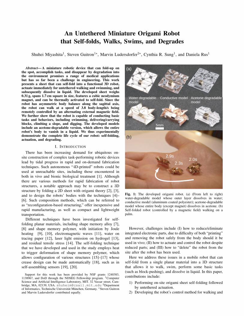
Fig. 1: The developed origami robot. (a) (From left to right)water-degradable model whose outer layer dissolves in water;conductive model (aluminum coated polyester); acetone-degradablemodel whose entire body (except magnet) dissolves in acetone. (b)Self-folded robot (controlled by a magnetic field) walking on apalm.
However, challenges include (I) how to reduce/eliminateintegrated electronic parts, due to difficulty of both “printing”and removing the robot safely from the body should it beused in vivo; (II) how to actuate and control the robot despitereduced parts; and (III) how to “delete” the robot from thesite after the robot has been used.
Here we address these issues in a mobile robot that canself-fold from a single planar material into a 3D structurethat allows it to walk, swim, perform some basic tasks(such as block-pushing), and dissolve in liquid. In this paper,contributions include:
1) Performing on-site origami sheet self-folding followedby untethered actuation.
2) Developing the robot’s control method for walking and
swimming using a newly developed electromagneticsystem.
3) Testing the robot’s ability to perform basic tasks andbehaviors.
4) Demonstrating the robot’s ability to degrade, as a proofof concept.
II. ROBOT STRUCTURE AND BEHAVIOR DESIGN
The goal for our robot is to self-reconfigure from a planarto a 3D structure, execute translational motion by walkingand swimming, and vanish into the environment, all in series.To achieve this goal, we designed an on-stage self-foldingtechnique (using global heating [15], [21] to catalyze therobot’s reconfiguration), employed remote magnetic controlfor the robot’s actuation, and utilized a specific material(polystyrene) for the robot’s structure so that it could dissolvein a liquid (acetone). This section presents the robot’s designand the actuation methods for both walking and swimming.
A. Force and Torque
The motion of the robot may vary depending on thedesired application and environment of use, we aim forwalking and swimming as basic capabilities. For a robotequipped with a magnet with magnetic dipole moment m,the force F and torque T that the robot experiences in amagnetic flux density B are
F = (m · ∇) B, (1)
T = m× B, (2)
where B is the globally created, superimposed magnetic fluxdensity of all the coils in the environment. Assuming that themagnet’s shape can be approximated as a sphere of radius a,m can be described with the saturation magnetization Msat
as
m =4
3πa3Msat, (3)
where Msat is intrinsic to the material of the magnet. Torqueis maximal when the relative angle between the magnetand the applied field reaches 90◦, and force is generatedproportionally to the gradient of the magnetic field.
B. Robot’s Design, Walking and Swimming Motion
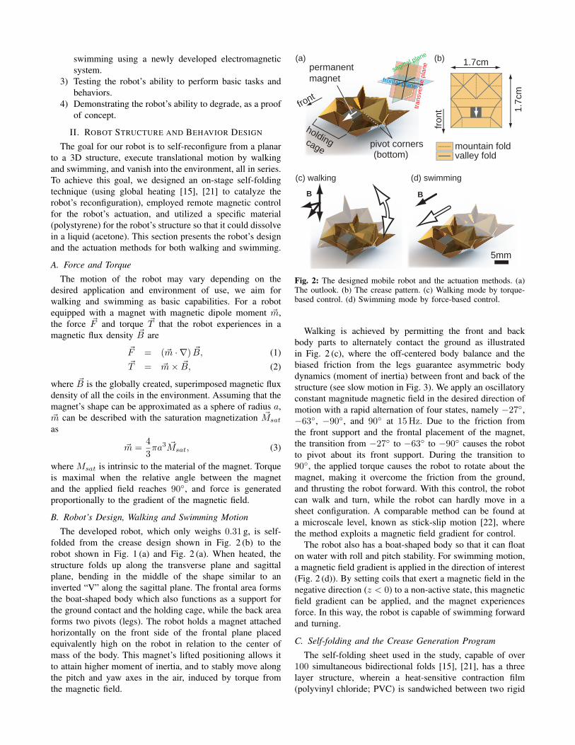
The developed robot, which only weighs 0.31 g, is self-folded from the crease design shown in Fig. 2 (b) to therobot shown in Fig. 1 (a) and Fig. 2 (a). When heated, thestructure folds up along the transverse plane and sagittalplane, bending in the middle of the shape similar to aninverted “V” along the sagittal plane. The frontal area formsthe boat-shaped body which also functions as a support forthe ground contact and the holding cage, while the back areaforms two pivots (legs). The robot holds a magnet attachedhorizontally on the front side of the frontal plane placedequivalently high on the robot in relation to the center ofmass of the body. This magnet’s lifted positioning allows itto attain higher moment of inertia, and to stably move alongthe pitch and yaw axes in the air, induced by torque fromthe magnetic field.
sagittal plane
transvers
e p
lane
frontal plane
mountain foldvalley fold
BB
pivot corners
permanent
magnet
holding cage
front
front
(a) (b)
(c) walking (d) swimming
5mm
1.7cm
1.7
cm
(bottom)
Fig. 2: The designed mobile robot and the actuation methods. (a)The outlook. (b) The crease pattern. (c) Walking mode by torque-based control. (d) Swimming mode by force-based control.
Walking is achieved by permitting the front and backbody parts to alternately contact the ground as illustratedin Fig. 2 (c), where the off-centered body balance and thebiased friction from the legs guarantee asymmetric bodydynamics (moment of inertia) between front and back of thestructure (see slow motion in Fig. 3). We apply an oscillatoryconstant magnitude magnetic field in the desired direction ofmotion with a rapid alternation of four states, namely −27◦,−63◦, −90◦, and 90◦ at 15Hz. Due to the friction fromthe front support and the frontal placement of the magnet,the transition from −27◦ to −63◦ to −90◦ causes the robotto pivot about its front support. During the transition to90◦, the applied torque causes the robot to rotate about themagnet, making it overcome the friction from the ground,and thrusting the robot forward. With this control, the robotcan walk and turn, while the robot can hardly move in asheet configuration. A comparable method can be found ata microscale level, known as stick-slip motion [22], wherethe method exploits a magnetic field gradient for control.
The robot also has a boat-shaped body so that it can floaton water with roll and pitch stability. For swimming motion,a magnetic field gradient is applied in the direction of interest(Fig. 2 (d)). By setting coils that exert a magnetic field in thenegative direction (z < 0) to a non-active state, this magneticfield gradient can be applied, and the magnet experiencesforce. In this way, the robot is capable of swimming forwardand turning.
C. Self-folding and the Crease Generation Program
The self-folding sheet used in the study, capable of over100 simultaneous bidirectional folds [15], [21], has a threelayer structure, wherein a heat-sensitive contraction film(polyvinyl chloride; PVC) is sandwiched between two rigid
1mm
0.798s
0.815s
0.831s
0.848s
0.864s
(a)
(b)
(c)
(d)
pivoting
magnetization
hit the ground
B -90
90
-27
-63
-90
(e) (same posture as (a))
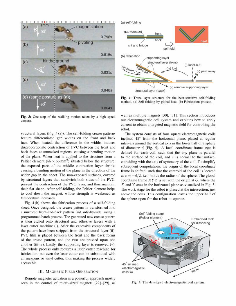
Fig. 3: One step of the walking motion taken by a high speedcamera.
structural layers (Fig. 4 (a)). The self-folding crease patternsfeature differentiated gap widths on the front and backface. When heated, the difference in the widths inducesdisproportionate contraction of PVC between the front andback faces at unmasked regions, causing a bending motionof the plane. When heat is applied to the structure from aPeltier element (55 × 55mm2) situated below the structure,the exposed parts of the middle contraction layer shrink,causing a bending motion of the plane in the direction of thewider gap in the sheet. The non-exposed surfaces, coveredby structural layers that sandwich both sides of the PVC,prevent the contraction of the PVC layer, and thus maintaintheir flat shape. After self-folding, the Peltier element helpsto cool down the magnet, whose strength is weakened astemperature increases.
Fig. 4 (b) shows the fabrication process of a self-foldingsheet. Once designed, the crease pattern is transformed intoa mirrored front-and-back pattern laid side-by-side, using aprogrammed batch process. The generated new crease patternis then etched onto structural and adhesive layers with alaser cutter machine (i). After the excessive components ofthe pattern have been stripped from the structural layer (ii),PVC film is placed between the front and the back formsof the crease pattern, and the two are pressed upon oneanother (iii-iv). Lastly, the supporting layer is removed (v).The whole process only requires a laser cutter machine forfabrication, but even the laser cutter can be substituted withan inexpensive vinyl cutter, thus making the process widelyaccessible.
III. MAGNETIC FIELD GENERATION
Remote magnetic actuation is a powerful approach mostlyseen in the control of micro-sized magnets [22]–[29], as
self-fold
gap (crease)
slit and bridge
front
back heat
supporting layer
structural layer (back)
(iv) fold(iii) insert PVC
structural layer (front)
(v) remove supporting layer
(b) fabrication
(a) self-folding
adhesive
adhesive (ii) peel away
(i) laser cut
Peltier element
Fig. 4: Three layer structure for the heat-sensitive self-foldingmethod. (a) Self-folding by global heat. (b) Fabrication process.
well as multiple magnets [30], [31]. This section introducesour electromagnetic coil system and explains how to applycurrent to obtain a targeted magnetic field for controlling therobot.
The system consists of four square electromagnetic coilsinclined 45◦ from the horizontal plane, placed at regularintervals around the vertical axis in the lower half of a sphereof diameter d (Fig. 5). A local coordinate frame xyz isdefined for each coil, such that the x-y plane is parallelto the surface of the coil, and z is normal to the surface,coinciding with the axis of symmetry of the coil. To simplifysubsequent computations, the origin of the local coordinateframe is shifted, such that the centroid of the coil is locatedat z = −d/2, i.e., minus the radius of the sphere. The globalcoordinate frame XY Z is set with the origin at O, where theX and Y axes in the horizontal plane as visualized in Fig. 5.The work stage for the robot is placed at the intersection, justabove the coils. This configuration leaves the upper half ofthe sphere open for the robot to operate.
45 inclined
electromagnetic
coils x4
Self-folding stage
(Peltier element)Embedded tank
for dissolving
x
yz
X
YZ
O
-d/2
50cm
operation area 20cm
20cm
Fig. 5: The developed electromagnetic coil system.

The magnetic flux density generated around a conductivewire traversed by a current I can be calculated after theBiot-Savart law
db =µ0I
4π
dw × r
|r |2, (4)
where µ0 is the vacuum permeability, dw is an infinitesimalsmall segment of the wire, r is the vector pointing fromdw to the point of interest at which the magnetic fluxdensity is to be calculated, and r is the unit vector pointingin that direction. Evaluating the contour integral over allinfinitesimal segments of the wire gives the overall magneticflux density generated at the point of interest [32]. Adaptingthis to the case of a square coil simplifies the contourintegral to four line integrals [22]. Thus, the magnetic fluxdensity b(x, y, z) generated at a position (x, y, z) relative to acoordinate frame associated with a square coil with N turnsof side length D, traversed by a current I , is given by [22],[33]
b(x, y, z) =
bx(x, y, z)by(x, y, z)bz(x, y, z)
=
µ0NI
4π
2∑k=1
2∑l=1
(−1)k+l+1 (z−c)(y−yl)
rxy
1rx
(−1)k+l+1 (z−c)(x−xk)rxy
1ry
(−1)k+l (x−xk)(y−yl)rxy
(1rx
+ 1ry
) ,
(5)
where x1 = y1 = −D/2, x2 = y2 = D/2,
rxy :=√
(x− xk)2 + (y − yl)2 + (z − c)2,
rx := (z − c)2 + (x− xk)2,
ry := (z − c)2 + (y − yl)2,
and c is the position of the centroid of the coil along thez-direction of the coordinate frame. Here, c = −d/2.
The globally created magnetic flux density B(X,Y, Z) isgiven by the superposition of the individual magnetic fluxdensities bL(X,Y, Z) generated by the four electromagnets,expressed in global coordinates. That is,
B(X,Y, Z) =
4∑L=1
bL(X,Y, Z). (6)
To derive each individual bL(X,Y, Z), (5) has to be rotatedto match the orientation of the respective coil relative to theglobal coordinate frame, as depicted in Fig. 5. Furthermore,a coordinate transform has to be introduced to express eachlocal coordinate set in the global coordinates. This yields
bL(X,Y, Z) = RLb(xL, yL, zL), L = 1, . . . , 4. (7)
The four 3 × 3 rotation matrices RL := R(α), where α ∈{0, π/2, π, 3π/2} describes the orientation of the local framewith respect to the global one [34], are given by
R(α) =
cosα2 + sinα√
2cosα2 − sinα√
2− cosα√
2sinα2 − cosα√
2sinα2 + cosα√
2− sinα√
212
12
1√2
. (8)
With these, the coordinate transform becomesxL
yLzL
= R−1L
XYZ
. (9)
Relation (6) is linear in the currents IL and therefore can berewritten as
B(X,Y, Z) = J(X,Y, Z) I , (10)
where J(X,Y, Z) is a 3×4 Jacobian matrix relating currentI to magnetic flux density B(X,Y, Z).
One solution for the current I required to generate adesired magnetic flux density B(X,Y, Z) at the stage canbe determined by solving the unconstrained least squaresproblem
minimizeI
∥J(X,Y, Z) I − B(X,Y, Z)∥2 (11)
corresponding to the underdetermined system of equations(10). The least squares problem (11) can for instance besolved using the Moore-Penrose pseudo inverse of the Jaco-bian matrix J
I = J#B, J# = JT (JJT )−1, (12)
where the position dependence of J(X,Y, Z) andB(X,Y, Z) has been omitted for clarity. This minimizesthe Euclidean norm of I , thereby minimizing both energyconsumption and heat generation [27].
The torque T acting on a magnet due to B(X,Y, Z)can be calculated from (2). The 3 × 3 skew-symmetricmatrix corresponding to m := (mX mY mZ)
T defined in (3)allows the cross product in (2) to be expressed as a matrixmultiplication. That is,
T =
0 mZ −mY
−mZ 0 mX
mY −mX 0
B(X,Y, Z). (13)
With (10) follows that T is linear in the currents I . Thereforethe previous equation can be rewritten as
T = JT (X,Y, Z) I , (14)
where JT (X,Y, Z) is a 3×4 Jacobian matrix relating currentI to torque T .
The force F acting on a magnet due to B(X,Y, Z) canbe calculated from (1). With equations (13.47a and b) from[35] follows
F =[∂B(X,Y,Z)
∂X∂B(X,Y,Z)
∂Y∂B(X,Y,Z)
∂Z
]m, (15)
where m as defined in (3). Therefore, F is linear in thecurrents I and can be rewritten as
F = JF (X,Y, Z) I , (16)
where JF (X,Y, Z) is a 3×4 Jacobian matrix relating currentI to force F . With (14) and (16) follows(
T
F
)=
[JT (X,Y, Z)JF (X,Y, Z)
]︸ ︷︷ ︸
:=A(X,Y,Z)
I = A(X,Y, Z) I , (17)

(a) (b) (c)
(d) (e) (f)
0s 10s 14s
28s 47s 68s
Fig. 6: Proof of concept of self-folding and immediate actuation of the robot. (a) Placement. (b)-(e) Self-folding. (f) Walking, all done insequence without physical intervention of an operator. See the attached video.
where A(X,Y, Z) is a 6× 4 actuation matrix describing thetorque and force acting on a magnet inside the area of oper-ation due to the currents applied to the four electromagneticcoils [27].
With this coil arrangement, the system is capable ofgenerating a magnetic field in an arbitrary direction at alocation sufficiently close to the center of the sphere. Auniform field is guaranteed with arbitrary strength alongthe X-Y plane, with a non-uniform field along the Z-direction. When a generated magnetic field only has X andY components, a magnet lying on the X − Y plane canturn while keeping its position (yaw motion). By includinga magnetic field component in the Z-direction, the magnetcan also face upwards (pitch motion), pivoting up from theground.
In the developed system, a magnetic field with a strengthof 0.6mT was measured in the Z-direction at point O witha total current flow of 10A (∼ 100W). This magnetic fieldstrength almost matched what was estimated with the model.A robot can be stably actuated within a circle of diameter∼ 20 cm, which is called the “operation area”, by employingrectangular coils of D = 20 cm. This operation area could bescaled up by employing the relationship found in (6). Giventhat c is to be increased while B should remain unchanged,N , D and I need to be adapted according to (5).
The X-Y direction of the magnetic field was controlled bythe joystick on an Arduino Esplora, whose MCU handles allof the computation. Current was drawn from a power supply,and commands were transferred from the MCU to fourSyRen 10 motor drivers (Dimension Engineering) throughpacketized serial communication in real time. Heating andcooling the Peltier element, switching between walking andswimming modes, and changing the magnitude of the mag-
netic field can all be controlled by either pressing a button oradjusting the slider on the Arduino Esplora controller. Therobot can also move from land to water by changing themode from torque-based walking to drag-based swimming.
IV. RESULTS
A. Self-folding and Immediate Action
We demonstrated on-stage self-folding as well as im-mediate actuation and showed the result as snapshots inFig. 6, as a proof of concept. After about 10 s from itsplacement (Fig. 6 (a)), the sheet started to self-fold at around65◦C (Fig. 6 (b)) beginning with longer creases that receivedthermal energy faster than the other creases (Fig. 6 (c)-(d)). The transformation was completed in about one minute(Fig. 6 (e)). The self-folded robot was actuated immediatelywithout human intervention after a short period of coolingdown (Fig. 6 (f)).
This integrated process shows that a functional structurecan be produced from a planar material and instantly beemployed for task operations.
B. Task Performances
The robot can complete various tasks due to its mobilecharacteristics. This section presents some examples of suchactions, controlled with a joystick. The robot can walk ina figure “8” pattern (Fig. 7 (a)), float and swim on water(Fig. 7 (b)), push and deliver a lightweight block (Fig. 7 (c)),carry two times (0.614 g) its weight (0.31 g) (Fig. 7 (d)),climb a slope of 8.5◦ (Fig. 7 (e)), walk on rough terrain(Fig. 7 (f), see also Fig. 1 (b)), and dig into a stack of sponges(Fig. 7 (g)).
During experiments, while the robot’s walking dynamicsmaintained stability, the robot often unexpectedly flipped
(a)
(b)
(c)
(d)
(e)
(f)
(g) robot
Fig. 7: Performances. (a) Walking on a trajectory. (b) Swimming.(c) Block delivery. (d) Carrying a load. (e) Climbing a slope. (f)Walking on rough terrain. (g) Digging through a stack. See theattached video.
over. This flip happened particularly when the robot suddenlychanged its walking direction to 180◦ opposite the originaltrajectory. Such instability can be avoided by restrictingthe change of the robot’s motion. The robot can recoverthe original posture by receiving an impulsive asymmetricmagnetic field.
C. Concept of Degradable Robots
This section demonstrates the degrading process of twodeveloped robots: (I) one whose entire body except for themagnet can dissolve in acetone, and (II) one whose outer
(a) (b)
(c) (d)
0:00
13:2312:57
1:57
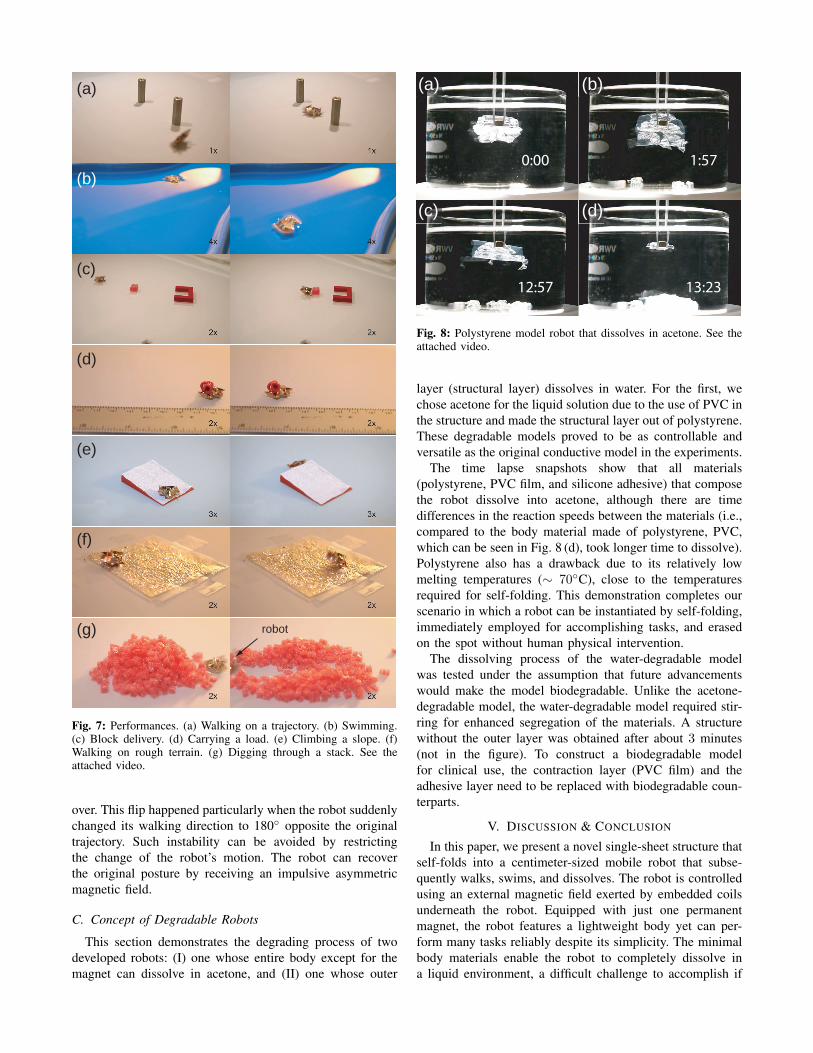
Fig. 8: Polystyrene model robot that dissolves in acetone. See theattached video.
layer (structural layer) dissolves in water. For the first, wechose acetone for the liquid solution due to the use of PVC inthe structure and made the structural layer out of polystyrene.These degradable models proved to be as controllable andversatile as the original conductive model in the experiments.
The time lapse snapshots show that all materials(polystyrene, PVC film, and silicone adhesive) that composethe robot dissolve into acetone, although there are timedifferences in the reaction speeds between the materials (i.e.,compared to the body material made of polystyrene, PVC,which can be seen in Fig. 8 (d), took longer time to dissolve).Polystyrene also has a drawback due to its relatively lowmelting temperatures (∼ 70◦C), close to the temperaturesrequired for self-folding. This demonstration completes ourscenario in which a robot can be instantiated by self-folding,immediately employed for accomplishing tasks, and erasedon the spot without human physical intervention.
The dissolving process of the water-degradable modelwas tested under the assumption that future advancementswould make the model biodegradable. Unlike the acetone-degradable model, the water-degradable model required stir-ring for enhanced segregation of the materials. A structurewithout the outer layer was obtained after about 3 minutes(not in the figure). To construct a biodegradable modelfor clinical use, the contraction layer (PVC film) and theadhesive layer need to be replaced with biodegradable coun-terparts.
V. DISCUSSION & CONCLUSION
In this paper, we present a novel single-sheet structure thatself-folds into a centimeter-sized mobile robot that subse-quently walks, swims, and dissolves. The robot is controlledusing an external magnetic field exerted by embedded coilsunderneath the robot. Equipped with just one permanentmagnet, the robot features a lightweight body yet can per-form many tasks reliably despite its simplicity. The minimalbody materials enable the robot to completely dissolve ina liquid environment, a difficult challenge to accomplish if
the robot had a more complex architecture. This study isthe first to demonstrate that a functional robotic device canbe created and operated from the material level, promisingversatile applications including use in vivo. Our future workinvolves combining the conductive robot body with self-folding sensors [20] to achieve a higher level of autonomyand more versatility in function.
ACKNOWLEDGMENT
We thank Paige Studer, Anna C. Leonard, and AndresSalgado-Bierman for their assistance in experiments and infabrication of the self-folding sheets.
REFERENCES
[1] D. D. Damian, S. Arabagi, A. Fabozzo, P. Ngo, R. Jennings, M. Man-fredi, and P. E. Dupont, “Robotic implant to apply tissue tractionforces in the treatment of esophageal atresia,,” in IEEE InternationalConference on Robotics and Automation (ICRA), 2014, pp. 786–792.
[2] R. J. Lang, Origami Design Secrets. CRC Press, Taylor & FrancisGroup, 2012.
[3] Z. Abel, E. D. Demaine, M. L. Demaine, S. Eisenstat, A. Lubiw,A. Schulz, D. L. Souvaine, G. Viglietta, and A. Winslow, “Algorithmsfor Designing Pop-Up Cards,” in 30th International Symposium onTheoretical Aspects of Computer Science (STACS 2013), vol. 20, 2013,pp. 269–280.
[4] A. M. Hoover, E. Steltz, and R. S. Fearing, “RoACH: An autonomous2.4g crawling hexapod robot,” in IEEE/RSJ International Conferenceon Intelligent Robots and Systems (IROS), 2008, pp. 26–33.
[5] J. P. Whitney, P. S. Sreetharan, K. Ma, and R. J. Wood, “Pop-up bookMEMS,” Journal of Micromechanics and Microengineering, vol. 21,no. 11, p. 115021, 2011.
[6] C. D. Onal, R. J. Wood, and D. Rus, “Towards printable robotics:Origami-inspired planar fabrication of three-dimensional mecha-nisms,” in IEEE International Conference on Robotics and Automation(ICRA), 2011, pp. 4608–4613.
[7] E. Hawkes, B. An, N. M. Benbernou, H. Tanaka, S. Kim, E. D.Demaine, D. Rus, and R. J. Wood, “Programmable matter by folding,”Proceedings of the National Academy of Sciences, vol. 107, no. 28,pp. 12 441–12 445, 2010.
[8] A. Firouzeh, Y. Sun, H. Lee, and J. Paik, “Sensor and actuatorintegrated low-profile robotic origami,” in IEEE/RSJ InternationalConference on Intelligent Robots and Systems (IROS), 2013.
[9] S. M. Felton, M. T. Tolley, C. D. Onal, D. Rus, and R. J. Wood,“Robot self-assembly by folding: A printed inchworm robot,” in IEEEInternational Conference on Robotics and Automation (ICRA), 2013,pp. 277–282.
[10] S. Felton, M. T. Tolley, E. Demaine, D. Rus, and R. J. Wood, “Amethod for building self-folding machines,” Science, vol. 345, pp.644–646, 2014.
[11] K. Yasu and M. Inami, “Popapy: instant paper craft made up in amicrowave oven,” in The 9th International Conference on Advancesin Computer Entertainment, 2012.
[12] C. Guberan. (2012). [Online]. Available: http://vimeo.com/39914902[13] S. Fusco, M. S. Sakar, S. Kennedy, C. Peters, R. Bottani, F. Starsich,
A. Mao, G. A. Sotiriou, S. Pan, S. E. Pratsinis, D. Mooney, and B. J.Nelson, “An integrated microrobotic platform for on-demand, targetedtherapeutic interventions,” Advanced Materials, vol. 26, p. 952957,2013.
[14] N. Bassik, G. M. Stern, and D. H. Gracias, “Microassembly basedon hands free origami with bidirectional curvature,” Applied PhysicsLetters, vol. 95, pp. 091 901–1–091 901–3, 2009.
[15] S. Miyashita, C. D. Onal, and D. Rus, “Self-pop-up cylindricalstructure by global heating,” in IEEE/RSJ International Conferenceon Intelligent Robots and Systems (IROS), 2013.
[16] M. T. Tolley, S. M. Felton, S. Miyashita, D. Aukes, D. Rus, and R. J.Wood, “Self-folding origami: shape memory composites activated byuniform heating,” The IOP Journal Smart Materials and Structures,vol. 23, p. 094006, 2014.
[17] S. Miyashita, I. DiDio, I. Ananthabhotla, B. An, C. Sung, S. Arabagi,and D. Rus, “Folding angle regulation by curved crease design for self-assembling origami propellers,” Journal of Mechanisms and Robotics,2015, doi:10.1115/1.4029548.
[18] B. An, S. Miyashita, M. T. Tolley, D. M. Aukes, L. Meeker, E. D.Demaine, M. L. Demaine, R. J. Wood, and D. Rus, “An end-to-endapproach to making self-folded 3d surface shapes by uniform heating,”in IEEE International Conference on Robotics and Automation (ICRA),2014, pp. 1466–1473.
[19] S. Miyashita, L. Meeker, M. Goldi, Y. Kawahara, and D. Rus,“Self-folding printable elastic electric devices: Resistor, capacitor,and inductor,” in IEEE International Conference on Robotics andAutomation (ICRA), 2014, pp. 1446–1453.
[20] S. Miyashita, L. Meeker, M. Goldi, M. T. Tolley, R. J. Wood, andD. Rus, “Self-folding miniature elastic electric device,” The IOPJournal Smart Materials and Structures, vol. 23, p. 094005, 2014.
[21] S. Miyashita, C. D. Onal, and D. Rus, “Multi-crease self-folding byglobal heating.” To appear in Artificial Life Journal.
[22] S. Floyd, C. Pawashe, and M. Sitti, “Modeling and experimental char-acterization of an untethered magnetic micro-robot.” The InternationalJournal of Robotics Research, vol. 28, pp. 1077–1094, 2009.
[23] T. Honda, K. I. Arai, and K. Ishiyama, “Micro swimming mechani-jsms propelled by external magnetic fields,” IEEE Transactions onMagnetics, vol. 32, pp. 5085–5087, 1996.
[24] K. Ishiyama, M. Sendoh, and K. Arai, “Magnetic micromachines formedical applications,” Journal of Magnetism and Magnetic Materials,vol. 242-245, pp. 41–46, 2002.
[25] S. Martel, J.-B. Mathieu, O. Felfoul, A. Chanu, E. Aboussouan,S. Tamaz, P. Pouponneau, L. Yahia, G. Beaudoin, G. Soulez, andM. Mankiewicz, “Automatic navigation of an untethered device inthe artery of a living animal using a conventional clinical magneticresonance imaging system,” Applied Physics Letters, vol. 90, p.114105, 2007.
[26] K. Vollmers, D. R. Frutiger, B. E. Kratochvil, and B. J. Nelson,“Wireless resonant magnetic microactuator for untethered mobilemicrorobots,” Applied Physics Letters, vol. 92, no. 14, 2008.
[27] M. P. Kummer, J. J. Abbott, B. E. Kratochvil, R. Borer, A. Sengul, andB. J. Nelson, “Octomag: An electromagnetic system for 5-dof wirelessmicromanipulation,” in IEEE International Conference on Roboticsand Automation (ICRA), 2010, pp. 1006–1017.
[28] S. Miyashita, E. Diller, and M. Sitti, “Two-Dimensional MagneticMicro-module Reconfigurations Based on Inter-modular Interactions,”International Journal of Robotics Research, vol. 32, pp. 591–615,2013.
[29] E. Diller, J. Giltinan, G. Z. Lum, Z. Ye, and M. Sitti, “Six-degrees-of-freedom remote actuation of magnetic microrobots,” in Robotics:Science and Systems Conference, 2014.
[30] B. E. Kratochvil, D. R. Frutiger, K. Vollmers, and B. J. Nelson,“Visual servoing and characterization of resonant magnetic actuatorsfor decoupled locomotion of multiple untethered mobile microrobots,”in Proc. IEEE International Conference on Robotics and Automation(ICRA), Kobe, Japan, May 2009, pp. 1010 – 1015.
[31] E. Diller, J. Giltinan, and M. Sitti, “Independent control of multiplemagnetic microrobots in three dimensions,” International Journal ofRobotics Research, vol. 32, no. 5, pp. 614–631, 2013.
[32] P. A. Tipler and G. Mosca, Physics for Scientists and Engineers,6th ed. Palgrave Macmillan.
[33] W. M. Frix, G. G. Karady, and B. A. Venetz, “Comparison ofcalibration systems for magnetic field measurement equipment,” IEEETransactions on Power Delivery, vol. 9, no. 1, pp. 100–108, 1994.
[34] W. Khalil and E. Dombre, Modeling, Identification & Control ofRobots. Hermes Penton Science, 2002.
[35] I. N. Bronshtein, K. A. Semendyayev, G. Musiol, and H. Muhlig,Handbook of Mathematics, 5th ed. Springer-Verlag Berlin Heidelberg,2007.