an overview of offshore oil and gas · pdf filean overview of offshore oil and gas exploration...
TRANSCRIPT
Department of Trade and Industry
AN OVERVIEW OF OFFSHORE OIL AND GASEXPLORATION AND PRODUCTION ACTIVITIES
AUGUST 2001

Overview of Exploration and Production Activities
August 2001 Page 1 DTI SEA
CONTENTS
1 INTRODUCTION ................................................................................................. 3
1.1 Purpose........................................................................................................... 3
1.2 Scope and Structure of the Document ......................................................... 3
2 AN OVERVIEW OF OFFSHORE LICENSING.................................................... 3
3 EXPLORATION AND APPRAISAL .................................................................... 4
3.1 Introduction .................................................................................................... 4
3.2 Geophysical surveys...................................................................................... 5
3.2.1 Potential sources of effect ...................................................................... 6
3.3 Exploration and appraisal drilling................................................................. 8
3.3.1 Well objectives and planning.................................................................. 8
3.3.2 Drilling rigs............................................................................................... 8
3.3.3 Drilling operations ................................................................................... 9
3.3.4 Cementing .............................................................................................. 11
3.3.5 Logging and coring ............................................................................... 11
3.3.6 Well testing............................................................................................. 11
3.3.7 Well suspension and abandonment..................................................... 11
3.3.8 Abnormal operations............................................................................. 11
3.3.9 Appraisal wells....................................................................................... 12
3.3.10 Potential sources of effect................................................................. 12
4 FIELD DEVELOPMENT.................................................................................... 14
4.1 Development drilling.................................................................................... 14
4.2 Construction and installation...................................................................... 16
4.2.1 Possible types of production facility ................................................... 16

Overview of Exploration and Production Activities
DTI SEA Page 2 August 2001
4.2.2 Export facilities ...................................................................................... 18
4.2.3 Potential sources of effect .................................................................... 20
4.3 Commissioning ............................................................................................ 20
4.3.1 Potential sources of effect .................................................................... 21
5 PRODUCTION OPERATIONS.......................................................................... 21
5.1 Introduction .................................................................................................. 21
5.1.1 Atmospheric emissions ........................................................................ 21
5.1.2 Produced water and other aqueous discharges ................................. 22
5.1.3 Process and utility chemicals............................................................... 22
5.1.4 Logistics and support ........................................................................... 22
5.1.5 Well workover ........................................................................................ 22
5.1.6 Potential sources of effect .................................................................... 22
6 DECOMMISSIONING........................................................................................ 24
7 GLOSSARY & ABBREVIATIONS .................................................................... 25
8 SOME FURTHER READING............................................................................. 29
Overview of Exploration and Production Activities
August 2001 Page 3 DTI SEA
1 INTRODUCTION
1.1 Purpose
This document is intended to provide an introduction for non-specialists to the key activitiesand potential sources of environmental effects associated with oil and gas exploration andproduction. It forms part of the information base for the DTI’s Strategic EnvironmentalAssessment process which aims to facilitate public and other consultation on the potentialimplications of future licensing of offshore areas of the United Kingdom Continental Shelf.
1.2 Scope and Structure of the Document
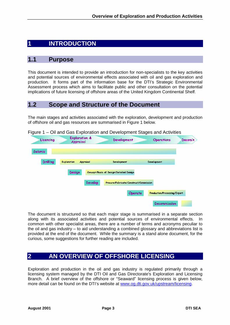
The main stages and activities associated with the exploration, development and productionof offshore oil and gas resources are summarised in Figure 1 below.
Figure 1 – Oil and Gas Exploration and Development Stages and Activities
Seismic
Exploration Appraisal Development DevelopmentDrilling
Concept/Basis of Design/Detailed Design Design
Procure/Fabricate/Construct/CommissionDevelop
Production/Processing/ExportOperate
Decommission
Exploration &Appraisal
Development Operations Decom’nLicensing
SeismicSeismic
Exploration Appraisal Development DevelopmentDrilling Exploration Appraisal Development DevelopmentDrilling
Concept/Basis of Design/Detailed Design Design Concept/Basis of Design/Detailed Design Design
Procure/Fabricate/Construct/CommissionDevelop Procure/Fabricate/Construct/CommissionDevelop
Production/Processing/ExportOperate Production/Processing/ExportOperate
DecommissionDecommission
Exploration &Appraisal
Development Operations Decom’nLicensing
The document is structured so that each major stage is summarised in a separate sectionalong with its associated activities and potential sources of environmental effects. Incommon with other specialist areas, there are a number of terms and acronyms peculiar tothe oil and gas industry – to aid understanding a combined glossary and abbreviations list isprovided at the end of the document. While the summary is a stand alone document, for thecurious, some suggestions for further reading are included.
2 AN OVERVIEW OF OFFSHORE LICENSING
Exploration and production in the oil and gas industry is regulated primarily through alicensing system managed by the DTI Oil and Gas Directorate's Exploration and LicensingBranch. A brief overview of the offshore or “Seaward” licensing process is given below,more detail can be found on the DTI’s website at www.og.dti.gov.uk/upstream/licensing.

Overview of Exploration and Production Activities
DTI SEA Page 4 August 2001
The first offshore licensing round took place in 1964 and the first significant discovery of gaswas made in the southern North Sea in 1965 and oil was discovered four years later in thecentral North Sea. Seaward licensing rounds have been held roughly every two years since1964 with the last, the nineteenth being held in 2000/2001. In January 2000, there were 109oil fields, 87 gas fields and 16 condensate fields in production offshore.
The Petroleum Act 1998, entered into force in 1999 and consolidated a number of provisionspreviously contained in five earlier pieces of primary legislation. The Act vests ownership ofoil and gas within Great Britain and its territorial sea in the Crown, and gives Governmentrights to grant licences to explore for and exploit these resources and those on the UKContinental Shelf (UKCS). Regulations set out how applications for licences may be made,and specify the Model Clauses to be incorporated into the licences.
There are two types of Seaward Licences:
• Exploration Licences which are non-exclusive, permit the holder to conduct non-intrusive surveys, such as seismic or gravity and magnetic data acquisition, over any partof the UKCS that is not held under a Production Licence. Wells may be drilled underthese licences, but must not exceed 350 metres in depth without the approval of theSecretary of State. These licences may be applied for at any time and are granted toapplicants who have the technical and financial resources to undertake such work. Eachlicence is valid for three years, renewable at the Secretary of State’s discretion for onefurther term of three years. Exploration licence holders may be commercial geophysicalsurvey contractors or licence Operators. A commercial contractor acquiring data overunlicensed acreage may market such data.
• Production Licences grant exclusive rights to holders “to search and bore for, and get,petroleum”, in the area of the licence covering a specified block or blocks. For licensingpurposes the UKCS is divided into quadrants of 1° of latitude by 1° of longitude (exceptwhere the coastline, “bay closing line” or a boundary line intervenes). Each quadrant isfurther partitioned into 30 blocks each of 10 x 12 minutes. The average block size isabout 250 square km (roughly 100 square miles). Relinquishment requirements onsuccessive licences have created blocks subdivided into as many as six part blocks insome mature areas. Production Licences are usually issued in periodic “LicensingRounds”, when the Secretary of State for Trade and Industry invites applications inrespect of a number of specified blocks or other areas.
Most activities carried out under a Exploration or Production Licence require the consent ofthe Secretary of State and may require compliance with other legislative provisions andspecific conditions attached to the consent.
3 EXPLORATION AND APPRAISAL
3.1 Introduction
The purpose of exploration activity is to identify commercially viable reserves of oil and gas.The conditions necessary for such reserves to have accumulated are complex and largelydependent on past geological history and present geological formations and structures. Forthe deposits to occur, particular combinations of potential source and reservoir rockstogether with migration pathways and trap structures are needed. Finding such reservoirs

Overview of Exploration and Production Activities
August 2001 Page 5 DTI SEA
and estimating the likelihood of them containing oil and gas is a technically complex processrequiring the use of a range of techniques. Such techniques include deep and shallowgeophysical (seismic) surveys, shallow drilling and coring, aero-magnetic/gravity surveysand exploration and appraisal drilling.
Based on a general geological understanding, broad areas of the earth have been identifiedas prospective, with the potential to contain reserves of oil and gas. Prospective areas arefurther defined using surface/shallow mapping techniques and geophysical (seismic) surveysto aid understanding of deeper, subsurface geology. Aero-magnetic and gravity surveys areuseful in defining general structure such as sedimentary basins but not for pinpointing areaswith potential oil and gas. Areas of potential interest are subjected to further geophysicalstudy, which may involve reinterpreting existing seismic data or conducting new surveys.The only reliable way to determine whether the identified formations contain hydrocarbons isto drill into them. However, the decision to drill is not taken solely on geological grounds.Government requirements, economic factors (drilling costs, transport costs, marketopportunities, relative merit/financial risk) and technical feasibility (including safety andenvironmental considerations) are all factored into the decision.
3.2 Geophysical surveys
Surface techniques do not allow reliable extrapolation as to the subsurface geology.Although other methods may be used for reconnaissance, seismic survey techniques remainthe most effective method of developing an understanding of the deep geology of an area.Seismic surveys are based on the same principles used to record data on subsurfacegeology during earthquakes but utilise a much smaller man-made energy source to generateenergy waves which are directed into the earth’s crust. Some of these energy waves arereflected or refracted back from geological structures deep beneath the surface and picked-up by sensitive detectors (geo- or hydrophones). Geophones are deployed at the ground orsediment surface and detect surface particle velocity whilst hydrophones are used principallyin marine seismic and detect pressure (sound) waves in water. The strength and speed withwhich the waves return is affected by the nature of the formations and other media throughwhich they have travelled. The data are recorded and interpreted using a combination ofcomputer software and experienced judgment to produce geological maps.
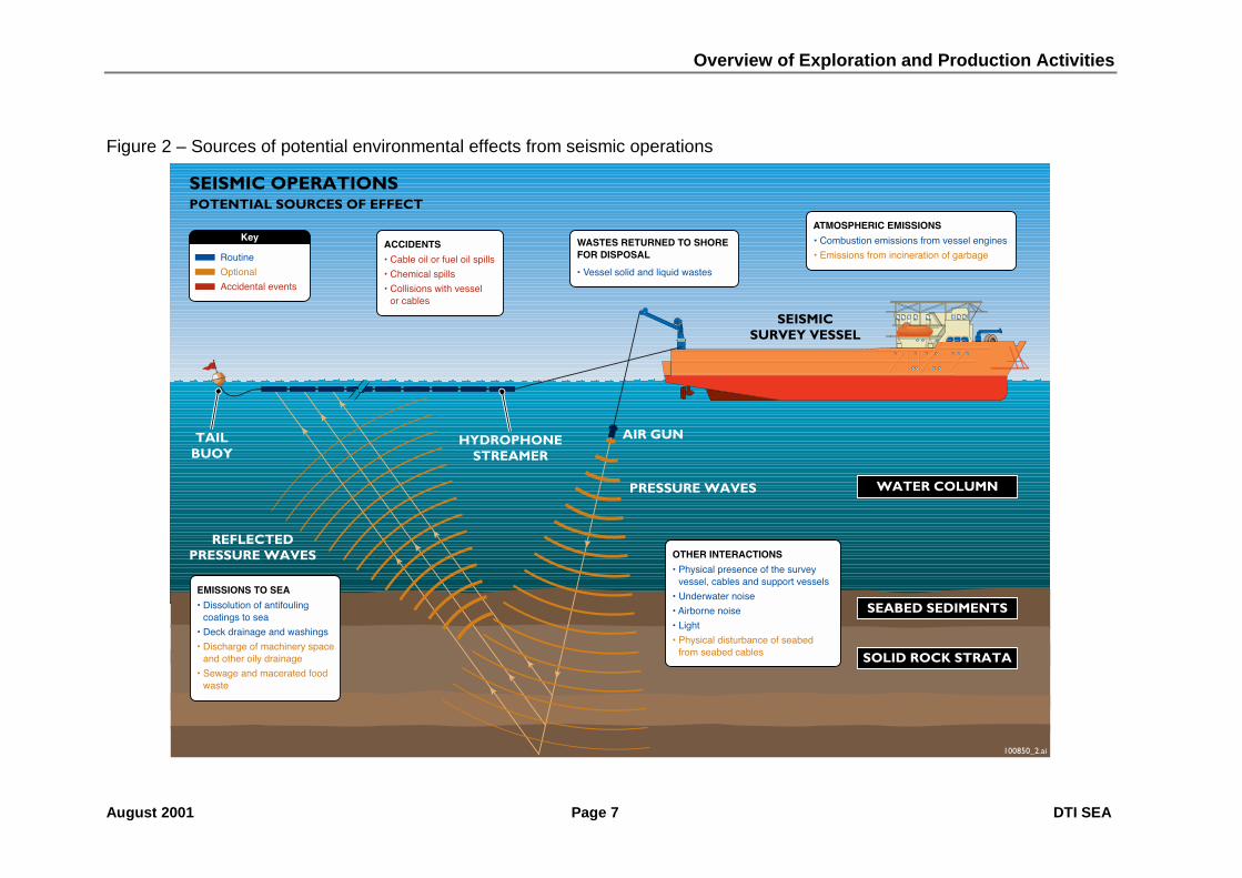
Marine seismic surveys are conducted from survey vessels which deploy a seismic source,normally an array of air guns, beneath the sea surface to generate pressure (sound) waveswhich transmit through the sea, sediment and the subsurface geological structures.Pressure waves reflected from subsurface structures are recorded by a series ofhydrophones, typically arranged at intervals along buoyant streamers towed just beneath thesea surface behind the vessel (Figure 2). Where floating streamers are used, correctionshave to be calculated to compensate for the drift induced by currents (feathering effect).
One or more guard vessels normally accompany marine seismic survey vessels, to liasewith fishermen and other small vessels and prevent collisions with the streamers etc.
On occasion, a multi-component system involving a combination of geophones andhydrophones may be deployed on the surface of the seabed. These are arranged alongcables which may be towed along behind the vessel (dragged array) or lifted and replaced ina new location as the survey progresses. Such surveys normally involve two vessels, oneattached to and processing the data from the sensors and one from which the source isdeployed. Multi component systems are considered to be better at penetrating throughsome structures which are opaque to traditional towed seismic survey techniques. This

Overview of Exploration and Production Activities
DTI SEA Page 6 August 2001
method of hydrophone deployment is not usually used in initial seismic survey. There aretwo types, a dragged array involving up to 750m of cable which can be used down to waterdepths of 2000m, or a dual sensor ocean bottom cable where up to 72km of cable is laid onthe seabed but only in waters of less than 200m. The deployment and retrieval of the cablesis intended to be along straight lines, and without lateral dragging although tidal and othercurrents can cause this to occur.
Seismic surveys mainly use 2-dimensional or 3-dimensional methodologies:• 2-D seismic utilises a single hydrophone streamer towed behind the survey vessel
together with a single source. The reflected pressure waves are assumed to lie directlybeneath the streamer and hence the nomenclature of 2-D. Repeated parallel lines aretypically run at intervals of several kilometres (minimum ca. 0.5km) and a second set oflines at right angles to the first to form a grid pattern. 2-D seismic provides a broadunderstanding of the geology of the area, however, its weakness lies in the interpretationof what is between the grid lines.
• 3-D seismic utilises one or more hydrophone streamers towed behind a vessel. Aseries of closely spaced (some 25 or 30 metres apart) parallel lines are run in a “racetrack” pattern to allow adjacent lines to be run in the same direction. Unlike 2-D no crossover lines are run. In simple terms, 3-D seismic collects a series of 2-D slices at veryclose intervals which can be interpreted to produce a 3-D understanding of the geologyof the surveyed area.
2-D seismic surveys can be conducted relatively quickly and inexpensively but the dataproduced, though valuable, does not give as accurate an understanding as 3-D surveys. Asa result, the majority of marine seismic surveys now conducted to identify oil and gasreserves are 3-D.
Data from seismic surveys may be reinterpreted as the result of information from othersources including exploration drilling. Seismic survey should not be viewed only as anexploration tool. Surveys are periodically conducted in areas with developed fields toprovide new information on the reservoir(s) and input to decisions on development drillingand reservoir management programmes.
In some developed areas, fixed arrays of seismic receivers (multi-component system) havebeen deployed on the seabed connected by a series of parallel cables to allow repeatedsurveys to be conducted over precisely the same area. This method provides as detaileddata as 3-D seismic but in addition, shows the temporal changes as oil is produced. Suchsurveys are therefore referred to as 4-D seismic.
On occasion, vertical seismic profiles (VSP) may be generated through the deployment intoa well of a number of geophones spaced on a cable. The seismic source is deployed in thewater column either suspended from the rig or platform (zero offset VSP) or from a sourcevessel at some distance from the well (offset VSP). VSP allows data from therocks/structures encountered during drilling to be correlated with seismic data. Suchsurveys are usually of short duration (1-2 days) and utilise sources with volumesintermediate between those used in typical seismic and rig site surveys (see Section 3.3.1).3-D VSP may, uncommonly be generated by making multiple passes with the source vessel.
3.2.1 Potential sources of effect
Potential sources of effect from seismic survey are shown on Figure 2.
Overview of Exploration and Production Activities
August 2001 Page 7 DTI SEA
Figure 2 – Sources of potential environmental effects from seismic operations

Overview of Exploration and Production Activities
DTI SEA Page 8 August 2001
3.3 Exploration and appraisal drilling
3.3.1 Well objectives and planningAs described above, the target structures to be drilled (bottom hole location) are identifiedprincipally from the interpretation of seismic survey information. Specific objectives aredefined early in the planning cycle for the well and in many respects define the nature andcost of the well to be drilled. The simplest objective for a first exploration well in an area (a“wildcat well”) may be to determine whether the structure identified contains oil and/or gas.The more complex the objectives, the longer the well may take and the greater the range oftests to be conducted. Objectives will define the information to be gathered during thedrilling including well logs and possible well test, and whether the well would be plugged andabandoned on completion of the programme or suspended for re-entry at a later date. Onoccasion, the well objectives may include provision for a sidetrack to the main well bore inthe event that hydrocarbons are encountered. The majority of hydrocarbon reserves on theUKCS lie between 2000 and 4500m below seabed although there are shallower and deeperreservoirs.
Surface hole locations (and therefore rig position) are normally chosen to achieve theshortest well consistent with avoiding surface hazards and sensitivities. Before a well isdrilled from a mobile drilling unit, information on the stability of surface sediments andpotential subsurface hazards (e.g. shallow gas formations) must be gathered to ensure thatthe rig will not encounter problems when positioning or drilling the surface hole. Rig sitesurveys utilise a range of techniques, including 2-D seismic survey, although for rig sitesurveys a much smaller energy source and shorter hydrophone streamer is used. Thesurvey typically covers a relatively small area of seabed, in the order of 2km or 3km square.The rig site survey vessel may also be used to gather baseline information on the seabedsediment, fauna and background contamination.
In scheduling a drilling operation the following are taken into account:• the weather and current conditions• seasonal environmental conditions and licence conditions• availability of rigs• commitments made to government• other company internal constraints and objectives
The well design, including the length and diameter of the various hole sections and casings,mud types (see Section 3.3.3) to be used, and contingencies allowed for, is dependent onthe nature of the rock formations to be drilled, the length of the well and the well objectives.The well design and plan is subject to external review and approval.
3.3.2 Drilling rigsExploration wells are almost invariably drilled from mobile drilling rigs. Rigs are basically ofthree types:• Jack-up rigs which are based on a buoyant steel hull with 3 or more lattice legs up and
down which the hull can be “jacked”. The rig is towed to location by 2 or more tugs withthe legs jacked up so the hull floats. On reaching the drilling location the rig jacks its hullup the legs until the base of the legs are firmly in contact with the sea floor and its deckpositioned above wave height. The rig's position is maintained by the legs which are infirm contact with the sea floor. No anchors are deployed, although in areas of strong

Overview of Exploration and Production Activities
August 2001 Page 9 DTI SEA
seabed currents where sediment scour may be expected, gravel or rock may be dumpedaround the base of the legs to stabilise the sediments. Jack-up rigs are depth limitedand can only operate in water depths of around 100m or less. These are the rigs whichare most often used in the shallower waters of the southern North Sea.
� Semi-submersible rigs which float at all times on pontoons are the most likely rig typeto be used in the deeper waters of the North Sea. The rig is towed to location by two ormore tugs. The pontoons contain ballast tanks, and the height of the deck above the seasurface can be altered by pumping ballast (sea) water in or out of the pontoons. Duringdrilling operations, the deck is lowered but still kept above wave height. Rigs used indeep water, harsh environments maintain position over the drilling location either byanchors (and where fitted, with rig thruster assistance as necessary) or by dynamicpositioning using a series of computer controller thrusters. Rig anchoring typicallyinvolves the deployment by anchor handler vessel, of eight or more 12 tonne highefficiency seabed penetrating anchors. The anchors are attached to the rig by cable andnear the anchor by chain, of which a proportion (a minimum of 100m) lies on the seabed(the catenary contact). Hauling in of the cables by the rig “sets” the anchors in theseabed after which minor adjustments to the rig position can be made by hauling orpaying out cable. The precise arrangement of anchors around a rig is defined by amooring analysis which takes account of factors including water depth, tidal and othercurrents, winds and seabed features. The relationship between water depth and lateralextent of the anchor pattern is not linear and typical radius of an anchor patterns for asemi-submersible drilling rig operating in a water depth of 100m is 1300 - 1400m.Anchors are retrieved by anchor handler vessels by means of pennant wires which slidedown the cable towards the anchor allowing a more or less vertical retrieval, facilitatinganchor breakout from the seabed.
• Drill-ships are based on a conventional ship’s hull adapted with a moon pool to allowthe deployment of the drill though the hull. They typically have their own motive powerand are not dependent on tugs, maintaining position with DP and/or anchors. Drill-shipscan operate in deep water and are the platform from which the academic Ocean DrillingProgramme is conducted. However because of the hull shape, they are more affectedby wind and wave movement than semi-submersible rigs, and as a consequence wouldbe more likely to suffer from weather down time.
Exploration rigs are self-contained with their own power generation, utilities andaccommodation facilities. Supplies are brought to the rig and wastes returned to shore bysupply boat. Crew are transferred on and off the rig by helicopter. For safety reasons, astand by vessel is deployed in the field for the duration of the drilling programme. A drillingderrick above the drill floor bears the weight of the drillstring, which is a series of 9m longsections of hollow drill pipe, screwed together and to the bottom of which the drill bit isattached. Additional sections of drill pipe are added to the drill string as the well is drilleddeeper. The lower part of the drill string, adjacent to the drill bit, is comprised of a series ofheavy drill collars to give added weight to the drill bit. The drill bit is rotated either by rotatingthe whole drill string by means of a rotary table on the drill floor/topdrive system or by adownhole turbine powered by the flow of mud pumped down the hollow drill pipe.
3.3.3 Drilling operationsOnce the rig is fixed in position, the well is commenced. A wide conductor (typically 30” or36”) is installed (spudded) into the surface of the seabed either by piling or using a water jet.The well is drilled in a series of steps with the hole sizes and casing getting progressivelysmaller. The upper section(s) of oil and gas wells is normally drilled “open” without a riser so

Overview of Exploration and Production Activities
DTI SEA Page 10 August 2001
that displaced sediments and rock are discharged directly around the wellbore. Theuppermost section of the well is sometimes made by water jetting rather than drilling, andcan result in a plume of sediment in the water column. The methods used and the depths towhich a surface hole is drilled are dependant on several factors, particularly well design andintended function and the nature of surface sediment/rock types. Side scan sonar and ROVinspection around exploration wells indicate that surface hole cuttings form a low mound witha radius of 5 to 10m around the wellhead.
A blow out preventer (BOP), comprising a series of hydraulic rams which can close off thewell in an emergency, is installed at the seabed. A riser (pipe) is deployed from the rig andconnected via the wellhead so that drill mud and cuttings from lower hole sections can bereturned to the rig for separation and treatment. The riser is fitted with devices to maintain itunder tension whilst compensating for heave.
Drilling muds are a combination of a weighting agent and other materials suspended in afluid (the base fluid). The choice of mud weight (specific gravity) and base fluid type (water,synthetic "oil" or low-toxicity oil) is dependent on the nature of the formations to be drilled.The weighting agent most commonly used is the dense mineral barites (barium sulphate).However in certain circumstances, including where local environmental sensitivities requirethis (e.g. where scallop beds are present), alternatives such as calcium carbonate may beused. The function of the mud is to provide:
• a circulation to remove cuttings from the hole• to cool the drill bit• and to provide a hydrostatic head to maintain well control by exerting a greater
pressure than that present in the well
Other chemicals are included in the mud formulation to aid its performance. Muds may bepremixed onshore and transported in the mud tanks of the rig, or via supply vessel, oralternatively they can be made on the rig.
The contaminant composition of drilling wastes has changed significantly over the last fewdecades, in response to technical and regulatory developments. Previous widespread andsubstantial discharges of oil-based muds, and later synthetic oil muds, have beensuperseded by alternative disposal methods (either containment and onshore treatment, orreinjection) or by water-based muds. The major environmental effects of development of theNorth Sea in the 1980s and early to mid 1990s, i.e. the formation of cuttings piles beneathplatforms and zones of benthic effects surrounding the platforms, are therefore unlikely to berepeated in future UKCS developments.
Base fluids are chosen on the basis of the formations to be drilled since certain rock types,such as shales, absorb water and expand, thereby potentially causing the drill pipe to stickand disrupting the drilling operation. If formations such as these are expected, then a non-water based fluid, either a synthetic or low-toxicity oil, may need to be used in those sectionsof the well.
Muds and cuttings are returned via the riser to the rig for treatment. Firstly cuttings andmuds are separated on shale shakers (vibrating screens) and the mud returned to the mudtanks for re-use. Cuttings from the shale shakers are normally either discharged, whendrilled with water based muds or in the case of synthetic or low toxicity oil based muds,contained for shipment to shore for further treatment and disposal. The opportunity to re-inject cuttings is not normally available for exploration and appraisal wells. The cuttings aremonitored for evidence of hydrocarbons by the mudlogger.

Overview of Exploration and Production Activities
August 2001 Page 11 DTI SEA
3.3.4 CementingAs each section of the well is drilled, the drill string is removed from the well and steel casinglowered into the well and cemented into place to prevent the well from caving in. Ameasured amount of quick drying cement slurry is pumped into the casing and a pluginserted above it. The cement is forced down to the bottom of the casing and then up theannulus (i.e. the space between the outside of the casing and the wall of the well) bypumping mud on top of the cementing plug. Pumping ceases once some cement isobserved returning with the mud returns indicating that all the mud in the annulus has beenreplaced with cement. Drilling activity is suspended, until the cement has set, the actual timebeing dependent on the cement additives used.
3.3.5 Logging and coringDependent on the original objectives, readings and sampling may be conducted in the lowersections of the well, particularly in potential reservoir rocks. Cores are taken by replacingthe drillbit with a core barrel which can cut rock cores several metres long. Othermeasurements, including porosity/permeability, electrical resistivity and formation densitymay be made using electronic/radiographic instruments lowered into the uncased, lowersections of the well using a wireline unit (wireline logging). If hydrocarbons are found, then adownhole tester is lowered into the well by wireline. This instrument measures fluidpressures and takes samples of the fluids.
3.3.6 Well testingWhere significant hydrocarbons are encountered, the well may be tested by installing asection of production liner in the lower hole and flowing the well to the surface for a shortperiod to measure pressures and flow rates and take samples of well fluids (well test or drillstem test). Prior to a well test, the well is cleaned up using a combination of high-densitybrines and clean-up chemicals to remove all traces of mud and cuttings debris from the bore.The brines are circulated to the rig via the riser and may be contained for reuse/disposal ordischarged overboard. The liner is then perforated in the reservoir section allowing reservoirfluids to flow into the liner bore and up to the rig. A gravel pack may be installed to preventproduction of unconsolidated sand from the reservoir with the fluids. The well fluids areprocessed on the rig, through a surge tank and a test separator, to provide information onthe relative proportions of gas, oil and water. The hydrocarbons produced during a well testare either burned in a high efficiency burner or in the case of oil produced during extendedwell tests, contained typically in a specialist storage vessel for transport to shore fortreatment.
3.3.7 Well suspension and abandonmentFollowing completion of the drilling programme the well is either abandoned or suspended.When being abandoned, the well is plugged with cement and the casing cut below thesurface of the seabed, (using a circular metal cutting tool attached to the bottom of the drillstring, or explosive charges). Suspending a well allows re-entry and involves plugging it withcement and capping the top hole casing. Following suspension or abandonment, a videodebris survey is conducted using a remotely operated vehicle (ROV) and any droppedobjects recovered.
3.3.8 Abnormal operationsOn occasion a mechanical failure of the tools down the hole may occur, for example afracture of the drill pipe. A range of “fishing” techniques and tools may be used to recover

Overview of Exploration and Production Activities
DTI SEA Page 12 August 2001
the equipment to the surface so that drilling can recommence. Should this be unsuccessfulthen the well may be plugged with cement and a (mechanical) sidetrack well drilled from justabove the plug and down to the target location.
The drill pipe may become stuck in some formations. The first approach is to attempt tocarefully jolt the pipe free. If this approach fails then a small amount (a "pill") of synthetic oroil base fluid may be used to help free the pipe, with the fluid recovered for disposal whencirculated to the rig.
Whilst drilling through porous formations, the drill mud may be lost into the pore spaces inthe rock resulting in a dramatic reduction in the amount of mud returned to the rig. Mudreturns are constantly monitored to aid early identification of such lost circulation. Lostcirculation is remedied by loading the mud with various materials to plug the porous rock e.g.cellulose strips, ground walnut shells.
In the event that gas, oil or water pressures exceed the hydrostatic head and invade the well(known as “a kick”) the back pressure is detected on the rig. Normally, the mud weight isincreased through the addition of weighting material to the point where downhole pressuresare balanced and contained. In extreme circumstances the blow-out preventer (a series ofhydraulic rams which can close off the well) is operated.
3.3.9 Appraisal wellsIf a hydrocarbon bearing reservoir is discovered during exploration drilling, one or moreappraisal wells may be drilled. Appraisal wells are used to delineate the physicaldimensions of the field and calculate its development potential. Such information isimportant in determining:
• whether it would be economically viable to develop the field• likely hydrocarbon production rates• appropriate process and export facilities
Most appraisal wells would normally include extensive logging and involve a well test.Because of the cost, as few appraisal wells as possible would be drilled, the actual numberbeing dependent on the particular circumstances of the field. Some appraisal wells aredrilled as future potential production wells and suspended following completion for future re-entry.
3.3.10 Potential sources of effectPotential sources of effect from exploration and appraisal drilling are shown on Figure 3.

Overview of Exploration and Production Activities
August 2001 Page 13 DTI SEA
Figure 3 – Sources of potential environmental effect from semi-submersible drilling operations

Overview of Exploration and Production Activities
DTI SEA Page 14 August 2001
4 FIELD DEVELOPMENT
A number of factors including field economics, availability of export routes, technicalfeasibility and environmental sensitivities are brought to bear on the decisions as to whether,when and how to develop a field for production. The development of a field is a stagedprocess (see Figure 4 below) with a great deal of activity taking place prior to thecommencement of construction work offshore. Environmental Impact Assessment is anintegral part of the selection of options, design, planning and execution processes.
Figure 4 – Offshore Design and Development Process
The summary description below focuses on the nature of the key potential field activities:• Drilling of development wells• Construction and installation of production and export facilities• Commissioning of the systems
4.1 Development drilling
The objective of a development drilling programme is to access as efficiently as possible therecoverable reserves from the field. The number of wells and locations from which they aredrilled are dependent on the size and nature of the reservoir. Development wells are oftendrilled over a period of time and both the temporal and areal spacing of the wells are
Design
Develop
ConceptSelection
Front EndEngineering Design
FEED
DetailedDesign
Operations
Fabrication
Procurement
Commissioning
Construction/Installation
Office
Onshore
Offshore
DevelopmentDrilling
Design
Develop
Design
Develop
ConceptSelection
Front EndEngineering Design
FEED
DetailedDesign
Operations
Fabrication
Procurement
Commissioning
Construction/Installation
Office
Onshore
Offshore
DevelopmentDrilling

Overview of Exploration and Production Activities
August 2001 Page 15 DTI SEA
dependent on the reservoir properties and field economics. The function of the wells thatmay be drilled during the life of a field would fall into the three broad categories:
• Production wells• Injection wells (water or gas)• Disposal wells ( cuttings, produced water or gas)
although it is sometimes possible to convert wells from one function to another.
In terms of operations and activities, development drilling is similar to exploration andappraisal drilling. The surface locations of development wells are normally centred at themain production facility and directional drilling techniques are used to access the differentparts of the reservoir. The drill string incorporates assemblies to weight and deflect the drillbit to the desired angle from vertical. Electronic/radiographic instruments are incorporated inthe string to relay to the surface information on location and angle of deviation of the drill bitand porosity and density of the formations. Because the frictional coefficient increases withthe angle of deviation, turbo drills or jet bit drills are used rather than rotary drills.Particularly where shales may be expected, the rheological properties of an oil based orsimilar mud may be required to prevent stuck pipe in these sections of the well. Thereservoir section of the well may be drilled more or less horizontal. In such cases one ormore horizontal sidetracks may be drilled from the same well to maximise access to thereservoir.
Where it is not technically feasible to drill to the target location from the main facility thendevelopment wells may be drilled at one or more satellite locations. However, to minimisefootprint and maximise use of infrastructure deviated drilling techniques are also used.
To reduce delay between the installation of the main facility and commencement ofproduction, some development wells may be predrilled from a mobile rig and temporarilysuspended. Where a number of wells are to be drilled from the same surface location asteel template may be deployed on the seabed rather than a series of individual guidebases. Templates are normally fixed on the seabed with two or more piles and also providefor accurate subsequent positioning of the jacket relative to the template. Cuttingsreinjection facilities are often not available at this stage and cuttings contaminated withsynthetic or low-toxicity oil based muds are contained and would be shipped to shore fortreatment.
Subsequent development wells at the main facility are either drilled from a drill rigpermanently installed on the facility or from a mobile drilling rig adjacent to a floatinginstallation or cantilevered over a fixed platform. The conductors for wells drilled from a fixedplatform extend from the seabed through slots on the facility with the wellhead and blow outpreventer located on deck. With floating facilities, the wellheads and blow out preventers areon the seabed and connected to the installation by flexible risers (see Figure 5). Followingcompletion of a production well, a valve assembly (Christmas tree) is installed on thewellhead, and production tubing installed in the well. The well is cleaned up using acombination of heavy brines and clean-up chemicals which are either discharged orcontained and shipped to shore for reuse/disposal dependent on type. Once all debris andmud has been cleaned from the well, well fluids will be flowed for a short period. Whereclean-up operations are being conducted on the platform, the well fluids will normally beprocessed. Satellite wells may be cleaned-up via a mobile rig and in these cases, the wellfluids may be disposed of via a high efficiency burner. Subsea wellheads are typically fittedwith various trawl protection structures to avoid snagging.

Overview of Exploration and Production Activities
DTI SEA Page 16 August 2001
Past development drilling using oil based muds has resulted in significant accumulations ofcontaminated cuttings under some platforms in the central and northern North Sea. Sinceonly cuttings from the surface hole and sections drilled with water based muds would bedischarged, significant accumulations of contaminated cuttings would not be expected fromfuture development drilling in the North Sea.
4.2 Construction and installation
4.2.1 Possible types of production facilityA range of different structures have been used to support offshore oil and gas production onthe UKCS including fixed, floating and subsea facilities, see Figure 5.
FixedFixed steel jackets are normally 4 or 6 leg structures, constructed of a welded steel tubularframework. The jackets are normally towed out to the development location andmanipulated into position by a heavy lift barge. Piles are driven into the seabed at each legto fix the jacket into place and the topsides lifted into place by in one or more lifts. Fixedsteel jackets are deployed in water depths of up to 450m. In some instances, to achieveseparation of accommodation and hydrocarbon processing, 2 or more platforms may beinstalled in proximity and bridge linked.
Concrete gravity base platforms are constructed out of concrete reinforced with steel andhave been used in locations where the seabed is too hard to permit piling. The platform issupported on concrete legs, at the base of which are ballast and storage tanks. Havingbeen towed out to the development location, the ballast tanks are flooded and the structuresettled on the seabed. Concrete structures have been used in water depths of up to 350m.
FloatingTension Leg Platforms (TLP) are floating structures, ballasted and anchored by tensionedsteel tendons to templates piled to the seabed. TLPs are relatively stable and can operate ina wide depth range (up to ca. 2,100m).
Floating Production Systems (FPS) and Floating Production, Storage and OffloadingSystems (FPSO) are facilities based either on ships’ hulls or semi-submersibles. They areballasted and anchored to the seabed, can accommodate vertical movement and operate ina wide depth range. Wells are normally fitted with subsea completions and produced to thefacility via flexible risers with built in compensation for vertical movement.
Both types of structures can operate in relatively deep water and are normally towed out tothe development location with the topsides facilities already pre-commissioned onshore.
SubseaSmaller fields or parts of the reservoir, which cannot be successfully accessed by directionaldrilling from the main facility location, are developed using a combination of subseacompletions, manifolds and pipelines tying the development back to a surface facility forfluids processing and export (host facility). Umbilicals with multiple cores are used to injectchemicals at the wellhead/manifold as necessary (e.g. to prevent the formation of hydratesor protect the pipeline from corrosion) and to support electric and hydraulic control of thewellhead and/or manifold valves from the main facility.

Overview of Exploration and Production Activities
August 2000 Page 17 DTI SEA
Figure 5 – Types of offshore facility

Overview of Exploration and Production Activities
DTI SEA Page 18 August 2001
It is not possible to be definitive as to which structures would be used for futuredevelopments in the North Sea, although it is likely that they would be based on acombination of floating and subsea structures and perhaps fixed platforms in the event of avery large discovery. A number of issues affect the selection of production facility includingexpected field life, reservoir fluid type and flow rates and location.
Offshore installations are self contained units with all the facilities needed to support themain processes and export including:
• power generation• pressure relief• water treatment• utilities• drains• helideck• cranes• crew accommodation
Drilling facilities may or may not be permanently installed depending on the type ofdevelopment. Structures are fitted with corrosion protection in the form of sacrificial anodesand/or impressed current systems.
4.2.2 Export facilitiesThe majority of oil production from the UKCS is exported to shore by pipeline with theremainder exported by tanker. Currently gas is only exported by pipeline, althoughtechnologies in development may allow the conversion of gas into liquids (gas to liquids) andtherefore export via tanker or oil pipeline. In fields with no economically viable export routegas surplus to fuel gas requirements is either injected into the reservoir for future recovery orother rock formations via disposal wells. The disposal of surplus gas by routine flaring isunlikely to be approved for any developments on the UKCS.
There is a well developed export pipeline infrastructure in the North Sea and production fromsmall new developments can be expected to be exported via existing facilities. Thedevelopment of very large new reserves could justify the installation of new pipelines andterrestrial reception facilities.
Tanker offloading requires both oil storage and offloading facilities. These may be providedby the main facility as, for example, in the case of FPSOs. Where insufficient storage isavailable on the main facility, a separate storage facility may be permanently anchored in thefield. Where the main or storage facility design does not permit safe approach by tankerthen an alternative mooring, for example, a single point mooring, is located a safe distance(up to several kilometres) away. Oil is transported by short infield pipeline(s) from the hostfacility to the storage and/or offloading units.
Marine oil and gas pipelines are laid either by anchored or dynamically positioned pipelaybarges, where sections of steel pipe are welded together to form the pipeline as the bargeprogresses along the pipeline route. Alternatively, a prefabricated pipeline is laid from alarge reel mounted on a dynamically positioned ship, although this technique has limitationsin terms of the size of pipeline that can be accommodated. Anchored pipelay barges usuallyhave an array of 12 anchors which are redeployed in sequence during pipelaying. Theanchor type is selected according to sediment and weather/current conditions of the areaand are normally either 12 tonne high efficiency seabed penetrating anchors or 20 to 25

Overview of Exploration and Production Activities
August 2001 Page 19 DTI SEA
tonne stockless general marine anchors. The anchors are attached to the barge by steelcables (typically 75mm in diameter) of which about a third to a half forms a catenary contacton the seabed. The anchors are repositioned by anchor handler vessels and dropped in acorridor between 2 and 3km wide centred on the pipeline. Each anchor is advanced about650m which results in a total of 24 anchor drops being made within the pipelay corridor foreach 1300m advanced (24 drops in an area of 2.8km2). Once dropped, the anchor cable ishauled in from the barge until a good hold is achieved. This normally drags the anchor alongthe seabed for between 5m and 50m depending on anchor type. The barge then uses theanchor spread to pull itself along as pipelaying progresses and during this process thecatenary contact cable is dragged across the seabed surface, resulting in cable scrape.Mounds of sediment up to 2m high may be formed in clay and mud seabeds during thepulling against the anchors or when the anchors are retrieved for redeployment.
The degree and nature of seabed scarring or disturbance during pipelay barge operations isdependant on a range of factors including:
• Laybarge type• The anchor type, size and weight• The nature of the seabed sediments• The load placed on the barge and hence the anchors by prevailing weather and
current conditions• Barge and anchor handler crew skill
Dynamically positioned (DP) vessels normally have no contact with the seabed other thanthe pipeline being laid. As a result of continuous thruster use to maintain station, DP vesselscan generate more underwater noise than conventional barges.
Large diameter (greater than 16 inches) pipelines are typically laid directly onto the surfaceof the seabed while smaller ones are normally trenched into it to a depth of about 1m. Thepipeline trench is either cut by plough where displaced sediment is sidecast or made bywater jet which disperses the removed sediment more widely as a plume in the watercolumn. Trenches are either backfilled with sidecast material or allowed to fill naturally overtime with sediments transported by tidal and other currents. Umbilical cables for the controlof subsea facilities are either placed alongside a buried pipeline in its trench or buriedseparately, normally using a marine version of the agricultural mole plough. The trenching istypically undertaken using equipment deployed from the laybarge or other support vessel.
In recent years, pipeline “bundles”, have been used for some developments. Pipelinebundles consist of a large diameter carrier pipe which contains a number of pipelines andoften the umbilical. Bundles are normally surface laid. The bundle is manufactured onshoreand towed out to the location in completed sections which are then filled with sea water(chemically treated to prevent corrosion of the bundle) and lowered to the sea floor.
Pipelines and subsea structures are fitted with corrosion protection in the form of sacrificialanodes, normally of aluminium.
Pressure testing (hydrotesting) of pipelines and subsea equipment with seawater is carriedout to detect leaks prior to use. The seawater typically includes a small quantity of a dyeand is normally. The treated seawater is normally discharged. The pipeline isdewatered/dried prior to use using a quantity of glycol and/or methanol or by using air dryingor vacuum drying techniques.

Overview of Exploration and Production Activities
DTI SEA Page 20 August 2001
4.2.3 Potential sources of effectPotential sources of effect from the construction, installation and pre-commissioning ofexport facilities are:
Atmospheric Emissions• Combustion emissions from vessel power generation
• Fugitive emissions from vessel fuel and chemical storage
Discharges to Sea• Hydrotest water
• Machinery space and other oily drainage from construction vessels
• Deck drainage and washings from construction vessels
• Sewage and food waste from construction vessels
• Dissolution of corrosion and antifouling protection from construction vessels
Other Interactions
• Physical disturbance to seabed from pipelaying/trenching, rock dumping andanchoring
• Physical presence of vessels
• Physical presence of pipelines and facilities
• Airborne noise
• Underwater noise
• Light
Wastes to Shore
• Solid and liquid construction and commissioning wastes
Accidents
• Fuel and other oil spills
• Gas releases
• Chemical spills
• Dropped objects
• Collisions
4.3 Commissioning
Much of the topsides process and utility equipment may be pre-commissioned onshore.Once the well(s) are brought on stream, final commissioning will be completed. As systemsare being fully commissioned and fine-tuned, some process “trips” normally occur, resulting
Overview of Exploration and Production Activities
August 2001 Page 21 DTI SEA
in shut down of part or whole systems and sometimes necessitating the disposal of gas toflare for a period.
4.3.1 Potential sources of effectCommissioning of facilities may result in short term changes in performance of the processsystems resulting in following potential sources of effect:
Atmospheric Emissions• Venting and flaring of gas
• Emissions from power generation
Discharges to water• Discharges of injected chemicals
• Produced water quality
5 PRODUCTION OPERATIONS
5.1 Introduction
The main function of the process system is to separate well fluids into the oil and gas phasesand condition them for transport by removing most of the water and solids.
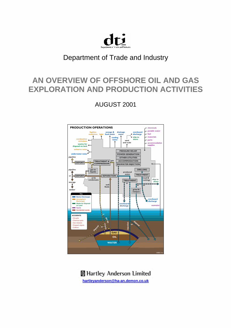
The principal production systems and options for export and disposal of emissions anddischarges are shown in Figure 6 overleaf.
5.1.1 Atmospheric emissionsThe major sources of emissions to atmosphere are internal combustion for power generationby installations, terminals, vessels and aircraft, flaring for pressure relief and gas disposal,cold venting and fugitive emissions.
Power requirements for the offshore industry are dominated by production installations(typically >50MW per platform), with substantially smaller contributions from mobile drillingunits (typically 10MW per unit) and vessels. The major energy requirement for production iscompression for injection and export, with power generated by gas or dual-fuel turbine(gas/diesel). Fuel gas accounts for over 60% of total CO2 emissions from the UKCSoperations.
Flaring from UKCS installations has been substantially reduced relative to historic levels,largely through development of export infrastructure and reinjection. New developments willgenerally flare in substantial quantities only for pressure relief, with “zero routine flaring” nowconsidered a realistic design target for planned developments.

Overview of Exploration and Production Activities
DTI SEA Page 22 August 2001
5.1.2 Produced water and other aqueous dischargesProduced water is derived from reservoir (“fossil”) water and from breakthrough of treatedseawater injected to maintain reservoir pressure, and is generally the largest singlewastewater stream in oil and gas production.
Other overboard discharges are generally of much lower volumes than produced water, andare unlikely to have significant effect, outside the immediate vicinity of fixed or mobileinstallations.
5.1.3 Process and utility chemicalsA range of process and utility chemicals are used in the offshore production of oil and gas.Chemicals may be contained in closed systems e.g. as heating medium or dependent onfunction, partition in whole or part with the oil or water phase. Examples of some of the keyfunctions of chemicals used offshore are to:
• Aid separation of fluids• Prevent foaming in process vessels and piping• Prevent the formation of hydrates• Inhibit corrosion of equipment and piping• Inhibit the build up of scale in equipment and piping• Treat and dry gas• Treat seawater
5.1.4 Logistics and supportSupplies to the facility (chemicals, diesel, parts, consumables, food and other supplies) andreturns from the facility (wastes, unused parts and chemicals etc) are transported to andfrom land by supply boat. Personnel are carried by helicopter.
A stand-by vessel is normally located in the vicinity of the main facility to provide safetycover and for oil spill response.
5.1.5 Well workoverDuring the life of a field, wells may be worked over to remedy faults or to improveperformance. Workovers are conducted either from the main facility, if a drilling rig ispermanently installed, or from a mobile rig brought into the field. The term workover coversa range of well intervention techniques including wireline and coiled tubing operations andoften involves the use of chemicals.
5.1.6 Potential sources of effectPotential sources of effect (in addition to the physical presence of the installation andassociated facilities) from production operations are shown in Figure 6.

Overview of Exploration and Production Activities
August 2001 Page 23 DTI SEA
Figure 6 – Sources of potential environmental effects from production operations

Overview of Exploration and Production Activities
DTI SEA Page 24 August 2001
6 DECOMMISSIONING
At the end of field life (less than 10 to more than 25 years) production and export facilitieswill be decommissioned.
Facilities will be decommissioned according to the requirements of UK, EU, OSPAR andother international regulations and agreements in force at the time. The methods used todecommission individual facilities would be selected on a case-by-case basis. Wells will beplugged with concrete and the conductors cut off below seabed level. Floating installationswould be towed away, potentially to a new location for reuse and associated risers andseabed anchor points removed. Similarly subsea manifolds will be removed. Pipelineswould be considered for removal on a case-by-case basis.
It should be noted that for a few decommissioned fields there may be the potential forredevelopment (re-commissioning) in response to technological advances and improvedeconomic conditions. Such redevelopments, would require the consent of the Secretary ofState and compliance with legislation in force.

Overview of Exploration and Production Activities
August 2001 Page 25 DTI SEA
7 GLOSSARY & ABBREVIATIONS
Term Definition
2D 2 Dimensional
3D 3 Dimensional
4D 4 Dimensional
Annulus The space between the drill string and well bore
Aqueous discharges Watery discharges to the sea
Barite Barium sulphate – a heavy mineral added to drillingmud as a weighting agent to increase its specificgravity and thus the hydrostatic head of the mudcolumn
Base fluid The liquid component of drilling mud
Bathymetry Measurement and study of ocean depth and floor
BOP (Blow-out preventor) Hydraulically operated device used to preventuncontrolled releases of oil or gas from a well
Christmas tree
(xmas tree)
Valve assembly at the top of a well used to controlflow of oil or gas
Combustion emissions Emissions of gases including carbon dioxide andoxides of nitrogen and sulphur, from the burning offossil fuels such as oil or gas
Condensate Liquid hydrocarbons, sometimes produced along withnatural gas
Contaminants Substances which may cause impurity or pollution
Corrosion protection Use of chemicals or sacrificial anodes to protect astructure from progressive breakdown by chemicalattack (or rusting)
Cuttings pile Pile of mainly rock chips deposited on the seabed as aresult of drilling
DP Dynamic Positioning
Drill bit A drilling tool used to cut through rock
Drill casing Steel pipe cemented into a well to prevent cave-in andstop fluids from leaking to or from surrounding rockinto the hole
Drill cuttings Rock chips produced as a result of drilling

Overview of Exploration and Production Activities
DTI SEA Page 26 August 2001
Term Definition
Drill string Lengths of steel tubing roughly 10m long screwedtogether to form a pipe connecting the drill bit to thedrilling rig. It is rotated to drill the hole and deliversdrilling fluids to the bit
Drilling mud Mixture of clays, water and chemicals used to lubricatethe drill bit and return rock cuttings to the surface; alsoused to maintain required pressure
DTI Department of Trade and Industry
Dynamic Positioning Use of thrusters instead of anchors to maintain theposition of a vessel
EC European Community
EEC European Economic Community
Environmental ImpactAssessment
Systematic review of the environmental effects aproposed project may have on its surroundingenvironment
EU European Union
Flare Controlled burning of gas for pressure relief (or duringwell testing to disposal of excess gas)
Formation An assemblage of rocks or strata
FPS Floating Production System
FPSO Floating, Production, Storage and Offloading Facility
Fugitive emissions Very small chronic escape of gas and volatile liquidsfrom equipment and pipework
Geology Physical structure and substance of the earth
GOR Gas Oil Ratio (ratio of gas to oil in producedhydrocarbons - expressed by volume)
Global Warming Rise in the earth’s temperature due to infra-redradiation being trapped in the atmosphere by watervapour, carbon dioxide and other gases
Greenhouse gases Gases believed to contribute to the greenhouse effect,including carbon dioxide, water vapour and methane
Hydrocarbon Compounds containing only the elements carbon andhydrogen, including oil and natural gas
Licence block Area of the sea which has been sub-divided andlicensed to a company or group of companies forexploration and production of hydrocarbons
Licensing round An allocation of licences made to oil companies

Overview of Exploration and Production Activities
August 2001 Page 27 DTI SEA
Term Definition
Liner Small diameter casing placed within a well to carryhydrocarbons back to the surface
Manifold Assembly of pipes, valves and fittings which allowsfluids from more than one source to be directed tovarious alternative routes
Mattresses Concrete structures used to protect pipelines or othersubsea structures
Organic compounds Materials containing carbon combined with hydrogen,often with other elements
OSPAR Oslo and Paris Commission
Permeability Degree to which a solid allows the passage of fluidthrough it
PON Petroleum Operations Notice
Porosity Degree to which a substance allows movement offluids through its pores
Produced water Water removed from the reservoir along with oil andnatural gas
Rheological Relating to flow or current
Riser Pipe connecting a rig or platform to a wellhead orpipeline
ROV Remotely Operated Vehicle
Sacrificial anodes Metal plates placed on underwater structures toprevent corrosion. The seawater attacks the anodesrather than the structure
Satellite wells Wells a considerable distance from the maindevelopment, connected via pipelines
Scale Minerals deposited on the inside of pipework andequipment. Some scales may contain low dose,naturally occurring radiation.
SEA (Strategic EnvironmentalAssessment)
An appraisal process through which environmentalprotection and sustainable development is consideredin decisions on policy, plans and programmes
Sediments Loose material, such as sand and mud, laid down atthe bottom of the sea, river or lake
Seismic Survey technique used to determine the structure ofunderlying rocks by passing acoustic shock waves intothe strata and detecting and measuring the reflectedsignals. Depending on the spacing of survey lines, theseismic is referred to as either 2 or 3-D.

Overview of Exploration and Production Activities
DTI SEA Page 28 August 2001
Term Definition
Shale Mud or claystone rocks
Shallow gas Gas accumulation present near the surface of theseabed
Sidetrack well Creation of a new section of well to detour around anarea or to reach another area
Tank washings Effluent as a result of cleaning tanks from rigs orvessels
Target location Position within a reservoir which is the target of thedrilling
TLP Tension Leg Platform
Trenching Excavation of a trench into the seabed in which apipeline or umbilical can be laid
UK United Kingdom
UKCS United Kingdom Continental Shelf
UKOOA United Kingdom Offshore Operators Association
Umbilical Flexible pipeline containing several different cores,which are used to carry electrical power, chemicalsand control fluids to the wellhead or other equipment
VOC (Volatile organiccompounds)
Organic compounds such as ethylene and benzenewhich evaporate readily and contribute to air pollutiondirectly or indirectly
VSP Vertical Seismic Profile
Wellhead Control equipment fitted at the top of a well
Wildcat well Exploration well in an area not previously drilled

Overview of Exploration and Production Activities
August 2001 Page 29 DTI SEA
8 SOME FURTHER READING
Boesch DF and Rabelais NN (1987). Long-term environmental effects of oil and gasdevelopment. Elsevier Applied Science, London.
Cairns WJ (1992). North Sea oil and the environment: developing oil and gas resources,environmental impacts and responses. Elsevier, Cambridge
DTI (2001). Development of UK Oil and Gas Resources 2001. The Stationery Office.
Engelhardt FR, Ray JP and Gillam AH (eds) (1989). Drilling Wastes. Elsevier AppliedScience, London. 867pp.
Environment Agency (1998). Oil and gas in the environment. Environmental Issues Series,The Stationery Office, 104pp.
Gallaway BJ, Senner RGB, Fechhelm RB and Hubbard GF (1997). Environmental trends inthe Gulf of Mexico in the twentieth century: The role of offshore oil and gas industry. Reportto the American Petroleum Institute, 110pp. Available at www.api.com
Gulland J and Walker C (1998). Marine seismic overview. In, Seismic and MarineMammals Workshop, 23-25 June 1998 (sponsored by AMJIG and IAGC).
Middleditch BS (ed) (1981). Environmental effects of offshore oil production, the Buccaneergas and oil field study. Plenum Press. 446pp.
Reed M and Johnsen S (eds) (1996). Produced Water 2: Environmental Issues andMitigation Technologies. Plenum Press.
Richardson WJ, Greene CR Jr, Malme CI and Thomson DH (1995). Marine Mammals andNoise. Academic Press.
Stockil P (Ed.) (1977). Our Industry Petroleum. The British Petroleum Company Limited,London. 600pp
Swan JM, Neff JM and Young PC (1994). Environmental implications of offshore oil and gasdevelopment in Australia - the findings of an independent scientific review. AustralianPetroleum Exploration Association, Sydney, 695 pp.
UK Offshore Operators Association and the Natural History Museum. Britain’s Oil and Gas.Second Edition. 55pp.
UKOOA (2000). Balancing Needs 2000 Environmental Performance Report.http://www.oilandgas.org.uk