an overview - sindusfarma€¦ · an overview luciana mansolelli ... zone a (e.g. filling machine...
TRANSCRIPT

As BPF aplicadas à produção de medicamentos de origem biológica AN OVERVIEW
Luciana Mansolelli
Microbiological Control and Vaccines
Agenda
The INPUT - OUTPUT Equation
The Challenges
The Tools at our disposal
Facilities – Some Essentials
HVAC - Some Essentials
CIP & SIP – Some Essentials
Utilities – Some Essentials
The INPUT – OUTPUT Equation
Consider sterile manufacturing from an „INPUT – OUTPUT“ point of view
Sterile manufacturing starts with mostly non sterile materials = the INPUT and ends with sterile materials = the OUTPUT
INPUT and OUTPUT are separated by the „point of sterility“
The key challenge of sterile manufacturing is to convert non sterile INPUT into sterile OUTPUT, and to maintain sterility once beyond the „point of sterility“

The INPUT – OUTPUT Equation
Question :
What are the OUTPUTS ?
The OUTPUT is by definition in almost all cases a sterile
product or material.

The INPUT – OUTPUT Equation
In specific cases the output is not necessarily sterile but the manufacturing process itself must be sterile
In biotechnology the upstream (cultivation) process part of e.g. recombinant antibodies production is sterile, but downstream (purification) is not (low bioburden)
In such cases „sterility“ is defined as the absence of contamination with organisms different from the ones we want to cultivate

The INPUT – OUTPUT Equation
Question :
What are the INPUTS ?

The INPUT – OUTPUT Equation
The INPUT consists of all elements involved directly or indirectly in the processes utilized to obtain the sterile OUTPUT
The INPUT consists of a heterogeneous list of items which are at different stages of microbiological purity when entering our processes
The INPUT – OUTPUT Equation
In case of a sterile pharmaceutical drug product the INPUTS are
• The APIs: Usually not sterile, with exceptions
• The inactive components (excipients): Usually not sterile
• The solvents: Usually Water for Injection (WFI), not sterile, at least by definition
• The gases: Air, Nitrogen, etc., usually not sterile, at least by definition
• The container systems: Usually not sterile, with exceptions
Note: In case of a sterile non pharmaceutical product, e.g. a contact lens care solution, the INPUTS are very similar

The INPUT – OUTPUT Equation
In case of a sterile API the INPUTS are
• The starting materials: Usually not sterile
• The solvents: Usually organic solvents and water of different grades, usually not sterile, at least by definition
• The bulk container systems: Usually not sterile, with exceptions

The INPUT – OUTPUT Equation
In case of a sterile biotechnology upstream process the INPUTS are
• The inoculum: Sterile (except for the organisms of interest)
• The media starting materials: Usually not sterile, with exceptions
• The solvents: Usually water of different grades, usually not sterile, at least by definition
• The gases: Air, Nitrogen, etc., usually not sterile, at least by definition
The INPUT – OUTPUT Equation
In case of a sterile contact lens the INPUTS are
• The starting materials: Usually not sterile
• The solvents: Usually water of different grades, usually not sterile, at least by definition
• The container systems: Usually not sterile

Material Raw material
Bioload is link to origin (synthetic vs vegetal or animal)
• Knowledge of bioload
- Bioburden testing/monitoring program
- WFI and Purified Water system monitoring program
Handling of raw material
• Specific sampling and weighing area
- same clean room classification than compounding/blending
• Specific container and wrapping
- To avoid contamination of environment or material
- To ensure proper entrance into the different clean rooms classification

Material Primary packaging material
Primary packaging are either sterile or non-sterile
• Sterile material
- Obtained by Heat sterilization, radio sterilization, Ethylene oxide,…
- Qualified vendor and validated sterilization process (audit program)
- Appropriate QA/QC release process to ensure review/assessment of critical sterilization’s parameters
- Appropriate transfer process in clean room
• Multiple wrapping
• Disinfection process

Material Primary packaging material
• Non sterile material for aseptic filling operation
- To be sterilized locally Heat sterilization (Autoclave, Oven/tunnel )
- Sterilization process to be validated with defined loading pattern or conveyor speed (tunnel)
- Routine operation to be run in line with validation parameters and wherever possible with a safety margin
- Sterilization Process parameters to be monitored and formally reviewed
- Appropriate transfer in Class A to be ensured

Material Transfer of Material
Objective is to avoid transfer of contaminant of lower cleanliness area into the higher cleanliness area
Preparation of material for transport in clean rooms
• Item to be bagged, covered until time of use
• Material used to bag or cover an item should be non particle generating
• Multiple layer of cover should be used to wrap material that have to enter area of different classification
- One layer is removed as item pass from one area to a cleaner one
- Final layer of cover must remain when being in the final area
Material Transfer of Material
Transfer in Class A and Class B processing area
• Preferred method is sterilization of the item using autoclave, dry heat oven or Vaporized Hydrogen Peroxide (VHP) chamber
- When double door sterilization equipment is used, item can be wrapped with one layer and is directly unloaded in the clean environment
- When item can not be unloaded directly in final clean environment it must be wrapped with multiple layer and enter final clean area via material airlock or pass through
• Alternative method is chemical sanitization with validated disinfecting agent and contact time
- After sanitization item is bagged with necessary layers and enter clean area via material airlocks or pass through
- When item can not be bagged after sanitization, environmental monitoring (viable count) should be conducted on the item upon exiting the area

Material Transfer of Material
Transfer in Class A and Class B processing area
• Other transfer method is Rapid Transport Port for isolator
- Pre -sterilized or in house sterilized material in bag with special connection port that allow transfer of material into isolator without breaking integrity

Material Transfer of Material
Key element in transfer of material in clean rooms
• Ensure removal of the different layer of bag protecting a sterilized or clean item without contamination of the next layer
• Use of chemical disinfectant and contact time which are validated for the defined use
• Provide written procedures to described the transfer practice for the different types of material
Operators to be trained on the SOPs and practices
The INPUT – OUTPUT Equation
By extension, the following elements will also be considered as INPUTS for any type of OUTPUT
• The processing equipment , small or large, reusable or disposable: Both not sterile and sterile
• The processing personnel: Never sterile, highly contaminating!
• The processing environment: Usually not sterile
• All other elements brought into the processing areas like gowns, disinfectants, records, monitoring tools
The INPUT – OUTPUT Equation
At all points before & during the process the non sterile INPUTS have to be selected with / kept at the lowest possible level of (micro)biological contamination
Choice of means to achieve this goal
• Purchasing specifications (purchased INPUTS)
• Production techniques & conditions, and specifications (self produced INPUTS)
• Protection by packaging and/or by equipment
• Protective environment
• Equipment cleaning & disinfecting
• (Pre) Filtration
The INPUT – OUTPUT Equation
At some point in the process the non sterile INPUTS have to be made sterile
Choice of means
• Heat : Dry heat, moist heat / steam & superheated water
• Rays : Gamma radiations
• Filtration: 0.2 micron filters
In addition, although not considered as sterilizing but nevertheless very effective
• Gases : Hydrogen peroxide, Peracetic acid
• UV light
• Disinfectants
Note: This point can be the same as for the OUTPUT
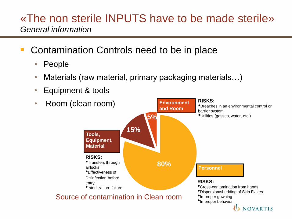
«The non sterile INPUTS have to be made sterile» General information
Contamination Controls need to be in place
• People
• Materials (raw material, primary packaging materials…)
• Equipment & tools
• Room (clean room)
RISKS: •Breaches in an environmental control or
barrier system
•Utilities (gasses, water, etc.)
Personnel
Environment
and Room
Tools,
Equipment,
Material
RISKS: •Cross-contamination from hands
•Dispersion/shedding of Skin Flakes
•Improper gowning
•Improper behavior
RISKS: •Transfers through
airlocks
•Effectiveness of
Disinfection before entry
• sterilization failure
80%
15%
5%
Source of contamination in Clean room

Clean rooms Routine monitoring
Viable particles
• Sampling location are based on the results of the initial qualification
• Minimum frequencies and limits depending on the cleanliness area as well as samples type are described in QM N15.19
• Glove monitoring to be implemented after critical intervention in Zone A (e.g. filling machine set up, …)
• All microorganisms recovered in Class A and B to be identified to the species level
• Trend analysis to be elaborated
• Alert limits to be periodically reevaluated (annually) based on statistical analysis
Clean rooms Routine monitoring
Non viable particle
• Sampling location with portable counter are based on the initial qualification results
• Continuous monitoring during activities in Class A
• No sample volume less than 1cft
• Action limits defined as per regulation requirements and Alert limits to be elaborated (e.g. 50% of action limits)
• Trend analysis to be elaborated
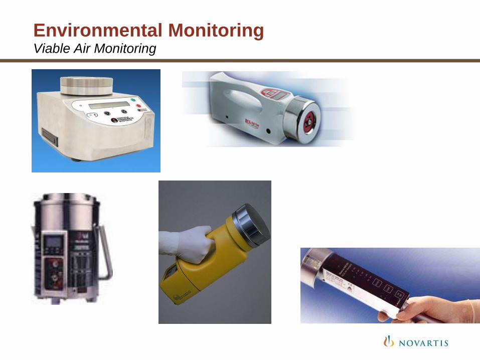
Environmental Monitoring Viable Air Monitoring
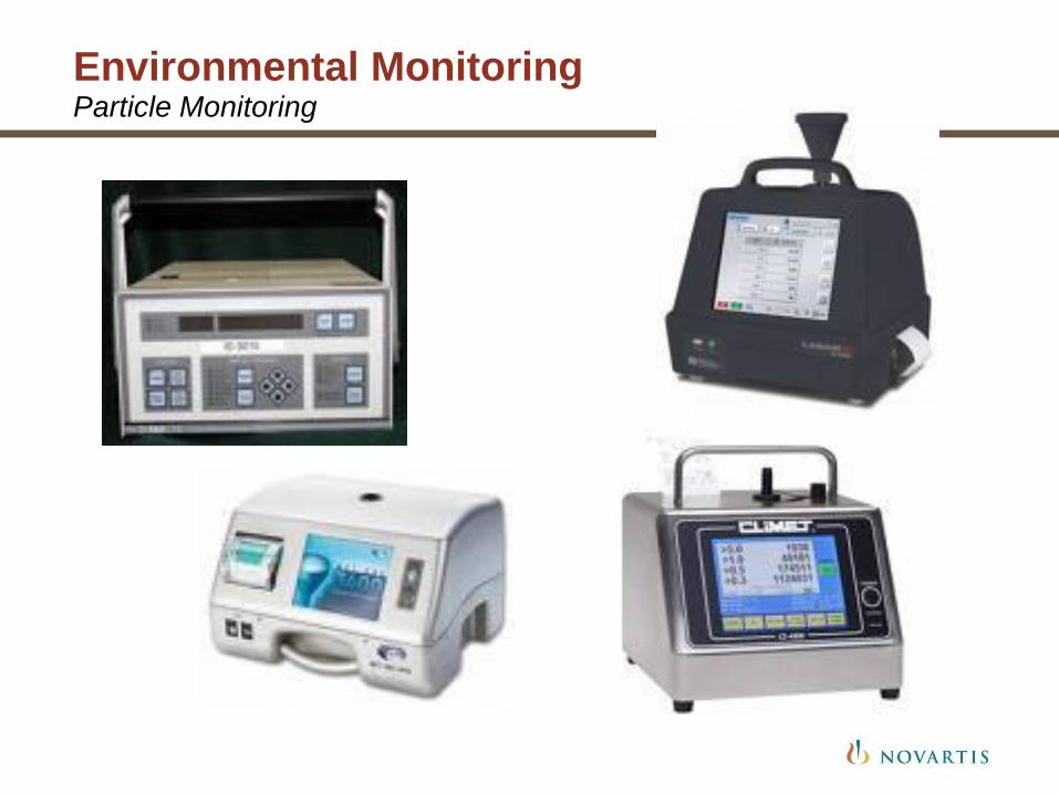
Environmental Monitoring Particle Monitoring
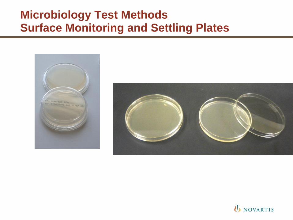
Microbiology Test Methods Surface Monitoring and Settling Plates

Surface Monitoring
Swabs
• Employed for equipment and irregular surfaces
• Sample area is usually 2” x 2” (equivalent to 25 cm2)
Types of Swabs
• Cotton
• Dacron
• Calcium alginate
Personnel Monitoring
Typically monitoring is performed using contact plates
Operators’ gloves are as critical as the surfaces they touch
Gloves can be monitored upon exit or upon completion of an aseptic operation
The outer pair of gloves should be changed upon completion of sampling

Personnel Monitoring
Operators’ sleeves and chest are viewed as critical as the gloves
Gown surfaces are sampled as the person exits from the APA
Gowns should be changed upon completion of sampling

Clean rooms Routine monitoring
Key elements
• All the environmental data generated during manufacturing of a sterile product are part of the batch release process
- Formal assessment of the set of data prior release
- In case of environmental excursion, deviation report to be closed prior release
• EM excursion results and trends
- Any sample result exceeding the action limits must be thoroughly investigated in order to assess product impact, clean room status and to identify Root cause
- Any adverse trend should also trigger similar type of investigation
- Use of CCTV in clean room is recommended as it will help witness the activities and specific situation in case of deviation and investigation

The INPUT – OUTPUT Equation
The INPUT - OUTPUT Equation is unfortunately one with numerous (partly unknown) variables
The sole chance to resolve the Equation is to ensure best possible control of all these variables
Controlling these variables presents however many challenges
We have at our disposal a box of tools
These tools are however only efficient and reliable if we ensure best possible control of them as well
The Challenges
Question :
What are the challenges ?

The Challenges
Almost all INPUTS have potential for transferring contamination into the process and the OUTPUT
Sterilizing of INPUTS and of OUTPUTS requires specific techniques adapted to the nature of the INPUTS, with specific validation
Not all INPUTS and OUTPUTS can be sterilized
Sterilized INPUTS can not all be staged in a Class A environment pending utilization.
The Challenges
Sterilized INPUTS protected by a tight packaging need to be unpacked -often manually- at some point
Sterilized INPUTS protected by a tight equipment need to be transfered into another equipment at some point
Only a Class A environment provides sterility assurance, the other cleanliness classes (2, D, C, B) do not
Full segregation between the sterile process and human operations is not always possible / not always provided
The Challenges
Human operations are always potentially contaminating
Human operations are more prone to errors than automated operations
(Micro)biological contamination is not detectable when it happens
Microbiological tests can not and do not provide an absolute proof of absence of microorganisms
More?

The tools at our disposal
Question :
What are our tools ?
The tools at our disposal
The sterilizing tools
• Dry heat ovens and autoclaves: For containers, short piping & tubing, small equipment, disposables, gowning parts, semi-finished products, batch records
• Sterilizing in place - SIP: For large containers & mobile tanks, fixed installed equipment & complex piping
• Gamma radiation: Only for materials purchased sterile. Small containers, short piping & tubing, disposables, gowning parts
• Sterilizing filtration: Limited to liquids (but not all) and gases
The tools at our disposal
The sanitizing tools
• Sanitizing agents: Applied manually (spray, wipe) or automatically (sanitizing chambers, fogging): For surfaces, non sterilizable materials and equipment
• Sanitizing in place: For large containers & mobile tanks, fixed installed equipment & complex piping that do not need to be sterile
By extension,we can also add
• Cleaning in place - CIP: The primary purpose of CIP is not to remove microbiological contaminants, however it actually often does
The tools at our disposal
The Facility
What tools can a Facility provide?

The tools at our disposal
Facilities permit to
• Control the intrusion of external contamination: HVAC systems, filters, pressure differentials, interlocked doors
• Control the propagation of contamination between areas/rooms : pressure differentials, interlocked doors
• Control contamination that was introduced or generated locally : filters, air exhausts/air changes
• Support segregation between non sterile and sterile process steps : Cleanliness Zones Concept
• Support segregation between non sterile INPUT and sterile INPUT & OUTPUT : Cleanliness Zones Concept

The tools at our disposal
Facilities permit to
• Reduce the contamination potential of the human factor: Changing airlocks, air showers, pressure differentials, interlocked doors
• Protect the sterile process from being contaminated and sterile INPUT & OUTPUT from being recontaminated : Class A air, physical segragation between Class A areas and the manned areas of lower grades
• Optimize process, material and personnel flows, reduce exposure at interfaces : Cleanliness Zones Concept, material airlocks, logical facility design supporting the process and personnel
The tools at our disposal
The Equipment
What tools can Equipment provide ?
The tools at our disposal
Equipment permits to
• Control the intrusion of external contamination: Closed systems, filters, overpressure
• Control contamination that was introduced or generated locally : Cleaning and Sterilizing, manually or CIP and SIP.
• Support segregation between non sterile and sterile process steps and between non sterile INPUT and sterile INPUT & OUTPUT : Segregated equipment trains, adequate transfer interfaces, physical barriers and air barriers
The tools at our disposal
Equipment permits to
• Eliminate the contamination potential of the human factor: closed systems, isolators, automated systems, fast aseptic connecting tools
• Reduce the contamination potential of the human factor:), conventional physical barriers and air barriers, improved physical barriers = Restricted Access Barrier Systems (RABS)
• Protect the sterile process and sterile INPUT & OUTPUT from being recontaminated

The tools at our disposal
Qualification & Validation
• Ensure Preventatively that Facilities, HVAC, Equipment, Utilities, CIP & SIP Systems and Processes are properly designed, constructed, installed, and operated to provide the best possible efficacy, reliability, and controls that technology allows, for the intended purpose

The tools at our disposal
Personnel Selection, Qualification, Training, Motivation, and Supervision
• The human element is the most contaminating and the least reliable element within the system
• The human element is involved directly and indirectly at all stages of sterile manufacturing
• Human errors can jeopardize the quality of the best facilities, equipment, and processes
• Prevention of human errors and detection of human errors is key
• Selection, Qualification, Training, Motivation, Supervision of the personnel are key factors

The tools at our disposal
None of these tools should be considered or optimized in an isolated manner
Only the harmonized combination of the tools and of the way they are utilized and interact provides the required state of the art level of control to resolve the INPUT - OUTPUT Equation satisfactorily
Even the best technology can fail, over confidence in the most sophisticated tools can be a dangereous attitude
Facilities – Some Essentials
A good facility is essential to support sterile manufacturing
A good facility requires a very carefull conception work
A carefull conception work must take into account a large number of factors
Data on these factors has to be as reliable as possible
One essential factor is the proper adjustment of facilities, equipment, and process
Facilities – Some Essentials
There is nothing like a standard facility
The concept should be challenged throroughly
Once built it is very difficult to modify a sterile manufacturing facility in a satisfying manner
„Right first time“ should be the driving idea
The best facility is only as good as the manner it will be operated
Equipment – Some Essentials
Modern technology provides a very wide array of equipment
Equipment should be selected to support the process and protect the sterile process and product from contamination
The best fit is provided by automated and closed equipment trains with no or minimum human interaction, in particular after the „point of sterility“
Where this is not the case the best protection from human-born contamination is never enough
Replacement of legacy equipment should be privileged over modernizing of legacy equipment.
Equipment – Some Essentials
Contamination often results from failing details, e.g. a leaking gasket or valve in a highly automated closed biotechnology upstream cultivation plant
Preventive maintenance is key
Limited savings on „cheep“ replacement parts can become very costly
Proper understanding of sophisticated equipment and of its limitations and potential failures by the users is key
Automation and computerization of equipment should not displace intelligent human thinking

HVAC – Some Essentials
A well designed HVAC concept requires a very accurate integrated conception work
HVAC can not be considered without considering the facility, the processes, the flows
No cleanliness zoning concept is possible without full integration of the HVAC concept
The relevance of HVAC is highest where technologies are conventional, e.g. with partly open processes, and is lowest where modern technologies, closed systems, are implemented.

HVAC – Some Essentials
HVAC (incl. clean rooms) qualification is essential
Airflow patterns qualification („smoke test videos“) at all locations were there is an intended pattern and under all conditions, is the only way to visualize and confirm the intended (designed) protection of the sterile process and product
Particular attention is required for aseptic manipulations involving human interaction in a Class A environment
Proper control, monitoring and alarming systems ensure continuous performance and proper action in case of failures.
CIP & SIP – Some essentials
CIP & SIP are not different from their manual counterparts in principles, objectives, and key constituting elements
Advantages = reproducibilty, no moving and no disassembling, less down times, less risk of damage and less risk of recontamination
Main differences = size, complexity, automation
Quality of design and construction are key
Absence of trapped residues is key in CIP
Saturated steam is key in SIP
CIP & SIP – Some essentials
Qualification & Validation needs are substantial
Validation of CIP is Cleaning Validation as usual
Validation of SIP is similar to validation of steam autoclaves
CIP & SIP even fully automated are not free of risks

Utilities – Some essentials
Water for Injection, Clean Steam, and Gases are the key utilities in sterile manufacturing
Their importance is very high in sterile manufacturing either as integral part of the products, or for being in direct contact with product containers and product contacting equipment surfaces (e.g. CIP and SIP)
The microbial contamination risk associated with these utilities, in particular Water, could in theory be very high, but in practice it is very low. These utility systems are usually well under control.
Exceptions exist but are rather due to a specific utilization or equipment design features than to the utility itself
Product Exposure & Interaction
By definition, the primary risk related to sterile products is the risk of microbial contamination
Terminally sterilized materials/products are at the lowest risk level
For products that are prepared aseptically or under sterile conditions the risk is highest during the process phases after the last step that can eliminate a potential contamination
The factors potentially contributing to microbial contamination are multiple

Product Exposure & Interaction
Thorough risk analyses are mandatory to identify all potential risks and provide the adequate technical and procedural solution(s)
Modern equipment concepts and design, if they can not completely eliminate the contamination risk, can reduce it significantly
Microbial contamination, although the biggest risk, is not the only one

Extended Slide Sets
The Extended Slide Sets are neither a digest of Regulatory Requirements nor a replication of existing Novartis Quality Modules or Implementation Guidelines. You should of course be familiar with these Standards.
The 6 Extended Slides Sets provide you with some considerations related to purpose, design, technologies, qualification & validation, and operation of the systems they cover
In addition they provide you some views of the potential issues linked with the systems based upon practical experience
Extended Slide Sets
Product Exposure & Interaction is a summary of the risks (sterile) products may be exposed to, and as such can serve as a background to the other Sets
I wish you good reading
Feel free to contact me anytime in future in case further clarification is needed

Questions ???
? ? ?

Sterilization processes Steam sterilization
Autoclave

Sterilization processes Steam sterilization
Use
• Sterilization of manufacturing equipment (pumps, filters, filling assemblies).
• Components (stoppers, capsules) .
• Product (buffers, media, final product)
Sterilization processes Steam sterilization
Principle
• Saturated steam
• Phase change from steam at 121ºC to condensate at 121ºC releases a large amount of energy (~2200 KJ/Kg).
• Typical minimum is 121 C for Not Less than 15 minutes (F0 = 15).
• The F0, at a particular temperature other than 121 C, is the time (in minutes) required to provide the lethality equivalent to that provided at 121 C for a stated time.
• Cycle can be controlled by the F0 calculated in real time by the equipment , or by a time / temperature measurement.
• Biological Indicators are used to provide assurance of sterility.
Sterilization processes Steam sterilization
Which of these scenarios do you think has the greatest killing effect?
30 minutes @ 115ºC
10 minutes @ 121ºC
1 minute @ 134ºC

Sterilization processes Steam sterilization validation
Temperature distribution studies: to be performed for each different cycle
• Empty sterilizer chamber:
- verification of consistency of temperature throughout the chamber
- 1 C of the set point (Not Less Than 12 points measured)
- three runs
• Loaded sterilizer chamber:
- verification of consistency of temperature throughout the chamber and the load: 1 C of the set point
- Chamber: same locations as empty chamber studies
- Load: see next slide

Sterilization processes Steam sterilization validation
Temperature penetration studies: to be performed for each different cycle
• Loaded sterilizer chamber: verification of consistency of temperature and lethality throughout the load:
- three runs for each load
- measure temperature and lethality (using BIs) at all “difficult to sterilize” locations in the load
• Examples for equipment load: in the middle of longest tubing; in filling pumps and needles, inside filters and filter housing; inside piles of gowning
• Examples for components: in the middle of the load inside the sterilization bags for rubber components such as stoppers, plungers, …
Validation studies performed using cycles run below the minimum limit of production cycle parameters (safety margin)
Sterilization processes Steam sterilization validation
What are the considerations when designing a load for the following;
• 6 meters of narrow bore silicone tube
• 2 Kg stainless steel valve.
• Product sterilising filters
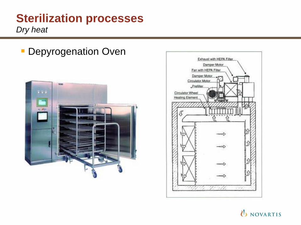
Sterilization processes Dry heat
Depyrogenation Oven
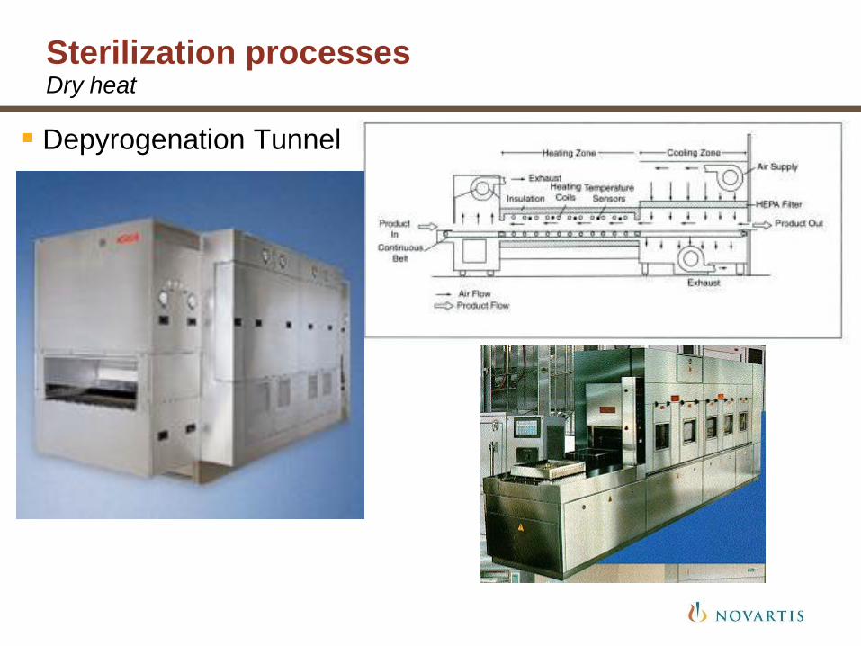
Sterilization processes Dry heat
Depyrogenation Tunnel
Sterilization processes Dry heat
High temperature filtered air used to sterilize and depyrogenate
Usually applies to glass containers
Two main types of sterilizers:
• Static load ovens
• Continuous load fed tunnels
Temperature: NLT 170 C, up to 350 C
Most sterilizers use temperature > 250 C
HEPA filtered air to maintain sterility and particle free environment
Loading in Grade C environment; unloading in Grade A
Sterilization processes Dry heat sterilization validation
Temperature distribution studies: to be performed for each different cycle
• Lethality measured in FH (equivalent to F0 for dry heat sterilization)
• Empty sterilizer chamber or tunnel:
- verification of consistency of temperature throughout the chamber: 5 C of the set point (Not Less Than 12 points measured); three runs
• Loaded sterilizer chamber or tunnel:
- verification of consistency of temperature throughout the chamber and the load: 5 C of the set point
- Chamber: same locations as empty chamber studies (does not apply to tunnels)
- Load: see next slide
Sterilization processes Dry heat sterilization validation
Temperature penetration studies: to be performed for each different cycle
• Loaded sterilizer chamber or tunnel: verification of consistency of temperature and lethality throughout the load:
- three runs for each load (use maximum load)
- measure temperature and lethality (using Endotoxin Indicators) at all “difficult to sterilize” locations in the load
- Endotoxin Indicators: glass containers spiked with reference endotoxin at a level sufficient to demonstrate at least a three log reduction in endotoxin
Validation studies performed using cycles run below the minimum limit of cycle parameters (safety margin)
• Below minimum cycle dwell temperature, shorter dwell time
• For tunnel, faster speed for the conveyor belt
• All parameters to be recorded and documented in validation documentation

Sterilization processes Dry heat sterilization validation
Which of these would be suitable for dry heat sterilisation?
• Glass Vial
• Syringe barrel with needle assembly attached
• Stainless steel tools for use in an isolator

Sterilization processes Sterile filtration
The sterile filtration is the ultimate step that will ensure sterility of a liquid product
There are four main elements, which ensure the sterility of the filtrate:
• The production control and quality assurance system of the filter manufacturer
• The filter sterilization
• The microbiological filter validation covering parameters specific to the product and the filtration process of the solutions.
• The proof of filter-integrity before and after sterile filtration.
Filter user must ensure that all four elements are taken into consideration, that they are in place and remain valid.
Sterilization processes Sterile filtration
Specific filter validation study to be performed
• Integrity test values
• Bacteria challenge test
• chemical compatibility, extractable matters, adsorption
• particle shedding,
• flow parameters (time, pressure differential…)
• toxicity testing,
• resistance to thermal stress (as needed)
Sterilization processes Sterile filtration
Routine activities need to ensure that operation is taking place within the defined filter validation parameters
• Perform pre and post filter integrity test
• Filtration time and pressure differential at the end of the process
• Bioburden test for each batch prior to the final sterilization filter
- Limits: 10 cfu/100 ml
or based on product historical data
to be recorded in Batch Record and formally assess against acceptance criteria
The INPUT – OUTPUT Equation
At all points in the process the already sterile INPUTS have to remain sterile
Choice of means to maintain their sterility
• Physical protection: a tight container or a closed equipment or system, either previously sterilized, or sterilized together with the INPUT.
• Environmental protection: Class A air or gas protection over the exposed / partly exposed INPUT

Introduction General information
The manufacture of sterile products is subject to special requirements in order to minimize risks of microbiological, pyrogen and particulate contamination.
Main objectives during manufacturing operation
• Avoid contamination during the process
• Maintain bioburden level of non sterile process steps to its minimum
• For sterile aseptic processing steps : maintain sterility
N.B.: Sterile pharmaceutical production encompass 2 types of production processes
• Aseptic production
• Final sterilization production
Clean rooms Cleanliness Zones
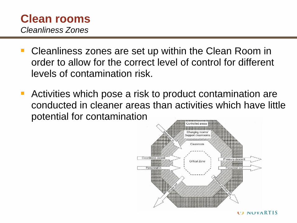
Cleanliness zones are set up within the Clean Room in order to allow for the correct level of control for different levels of contamination risk.
Activities which pose a risk to product contamination are conducted in cleaner areas than activities which have little potential for contamination
Clean rooms Cleanliness Zones
For the manufacturing of sterile drug products and sterile drug substances, five different cleanliness zones (A to E) are applied, depending on the process step and the degree of completion (proximity to the finished form) within the manufacturing sequence (i.e. before or after final filtration, etc.)
Clean rooms Cleanliness Zones
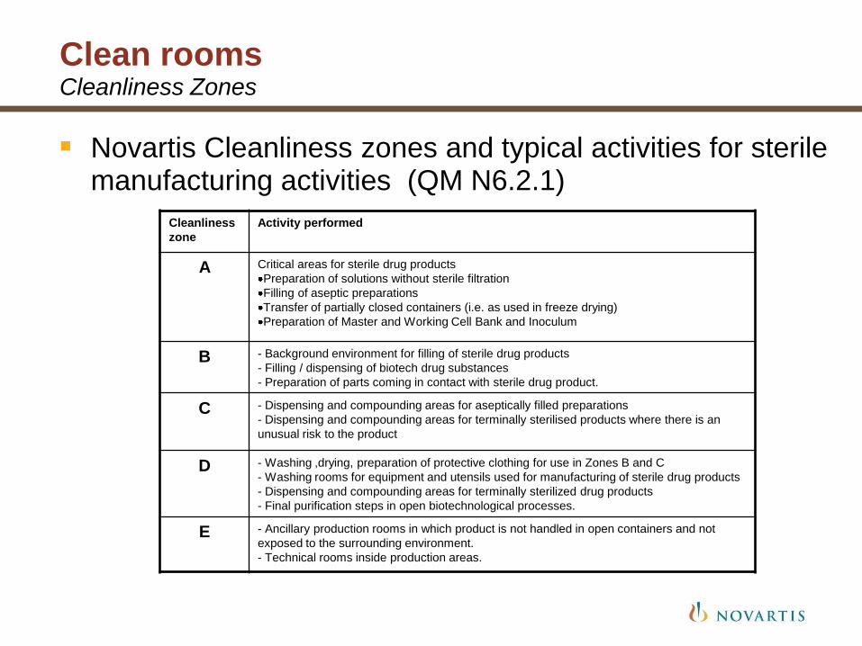
Novartis Cleanliness zones and typical activities for sterile manufacturing activities (QM N6.2.1)
Cleanliness
zone
Activity performed
A Critical areas for sterile drug products
Preparation of solutions without sterile filtration
Filling of aseptic preparations
Transfer of partially closed containers (i.e. as used in freeze drying)
Preparation of Master and Working Cell Bank and Inoculum
B - Background environment for filling of sterile drug products
- Filling / dispensing of biotech drug substances
- Preparation of parts coming in contact with sterile drug product.
C - Dispensing and compounding areas for aseptically filled preparations
- Dispensing and compounding areas for terminally sterilised products where there is an
unusual risk to the product
D - Washing ,drying, preparation of protective clothing for use in Zones B and C
- Washing rooms for equipment and utensils used for manufacturing of sterile drug products
- Dispensing and compounding areas for terminally sterilized drug products
- Final purification steps in open biotechnological processes.
E - Ancillary production rooms in which product is not handled in open containers and not
exposed to the surrounding environment.
- Technical rooms inside production areas.

Clean rooms Cleanliness Zones
Novartis Clean room Environmental limits (QM N15.16)
Zone
Max Non-Viable
Air Particles
(Static)
Max Non-Viable Air
Particles
(Dynamic)
Viable Air
(dynamic)
Settle Plates
(dynamic) Surface
A (ISO 5/5) 3500/ m3 (0.5µm)
20/ m3 (5.0µm)
3500/ m3 (0.5µm)
20/ m3 (5.0µm)
<1 CFU/m3
(average) <1 CFU/4 hr <1 CFU
B (ISO 5/7) 3500/ m3 (0.5µm)
20/ m3 (5.0µm)
350000/ m3 (0.5µm)
2000/ m3 (5.0µm) 10 CFU/m3 5 CFU/4/hr 5 CFU
C (ISO 7/8) 350000/ m3 (0.5µm)
2000/ m3 (5.0µm)
3500000/ m3 (0.5µm)
20000/ m3 (5.0µm) 50 CFU/m3
50 CFU/4 hr
(not required) 25 CFU
D (ISO 8/8)
3500000/ m3
(0.5µm)
20000/ m3 (5.0µm)
3500000/ m3 (0.5µm)
N/S (5.0µm) 100 CFU/m3
100 CFU/4 hr
(not required) 50 CFU
E N/S N/S N/S N/S N/S

Clean rooms Clean room initial qualification (non viable particles)
For the performance qualification minimum number of sampling locations according to EN ISO 14644-1
N = √ (clean room area surface).
in Zone A and B where fixed probes are going to be used the sampling location have to be evaluated in a Risk Assessment prior to initial qualification.

Clean rooms Clean room initial qualification (viable particles)
There are 3 components to Viable Environmental Monitoring Qualification:
• Baseline Monitoring
- to determine the challenge on the cleaning and disinfection regime
- to understand the microbiological flora ubiquitous to the area
• Static Monitoring (after cleaning and disinfection per site SOP)
- following the baseline monitoring when the facility is operating complete with production equipment but with no personnel present.
- to determine that the facility is functioning to its defined parameters microbiologically and that it can maintain its cleanliness zone.
• Dynamic Monitoring
- performed when the production facility is in operation with the defined number of personnel present.
- typically performed after static monitoring.
Clean rooms Clean room initial qualification (viable particles)
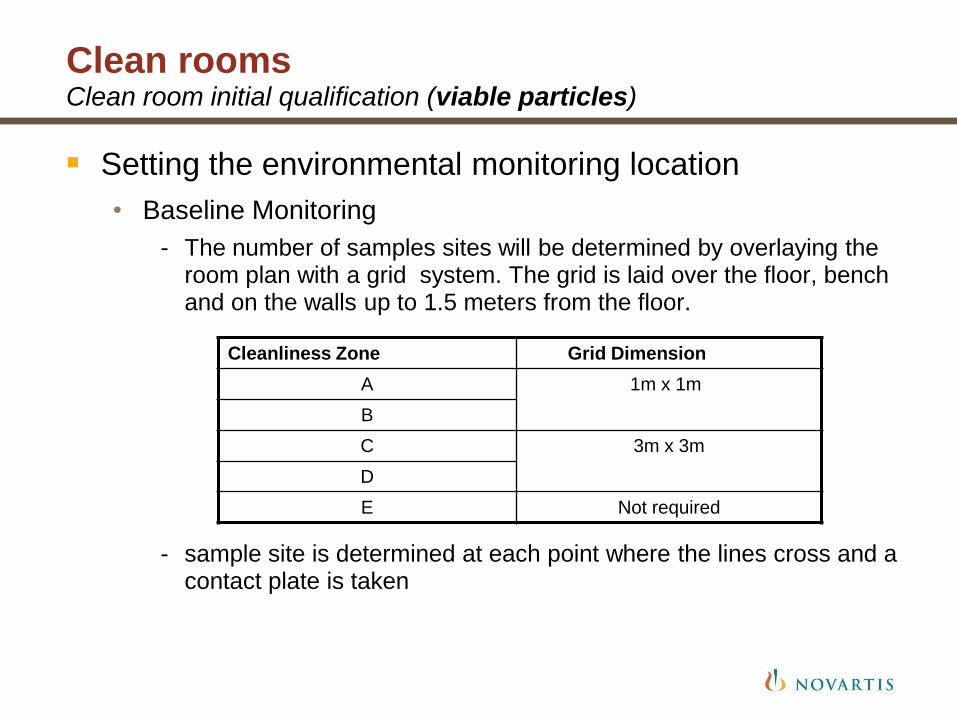
Setting the environmental monitoring location
• Baseline Monitoring
- The number of samples sites will be determined by overlaying the room plan with a grid system. The grid is laid over the floor, bench and on the walls up to 1.5 meters from the floor.
- sample site is determined at each point where the lines cross and a contact plate is taken
Cleanliness Zone Grid Dimension
A 1m x 1m
B
C 3m x 3m
D
E Not required

Clean rooms Clean room initial qualification (viable particles)
Setting the environmental monitoring location
• Static Monitoring
- The number of samples will be determined initially by the following equation:
N= √A
Where N = Number of Samples
A = surface of the room to be monitored
• N Samples are
» active air and settle plates in Zone A & B
» Active air in Zone C & D
- Static Monitoring is performed for a minimum of three occasions.
Clean rooms Clean room initial qualification (viable particles)
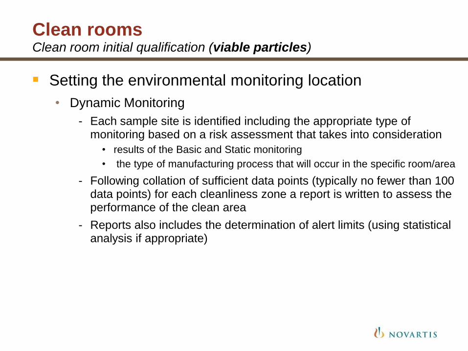
Setting the environmental monitoring location
• Dynamic Monitoring
- Each sample site is identified including the appropriate type of monitoring based on a risk assessment that takes into consideration
• results of the Basic and Static monitoring
• the type of manufacturing process that will occur in the specific room/area
- Following collation of sufficient data points (typically no fewer than 100 data points) for each cleanliness zone a report is written to assess the performance of the clean area
- Reports also includes the determination of alert limits (using statistical analysis if appropriate)
Elements of an Environmental Monitoring Program
Viable air monitoring
Total airborne particulate monitoring
Surface monitoring
Personnel monitoring
Temperature and relative humidity monitoring
Room air pressure differential monitoring
Tests Used for Environmental Monitoring Program
We will now go through each of the environmental monitoring methods used
First there will be a demonstration and discussion for each method
Once we have gone through all methods we will rotate through stations to practice the operation of the equipment and how to take surface monitoring