an ontology for interactive workspaces and their …
TRANSCRIPT

The Pennsylvania State University
The Graduate School
College of Engineering
AN ONTOLOGY FOR INTERACTIVE WORKSPACES
AND THEIR USE CASES WITHIN COLLABORATIVE DESIGN AND
CONSTRUCTION PRACTICES
A Thesis in
Architectural Engineering
By
Jennifer I. Lather
© 2016 Jennifer I. Lather
Submitted in Partial Fulfillment of the Requirements
for the Degree of Master of Science
May 2016

ii
The thesis of Jennifer I. Lather was reviewed and approved* by the following:
John I. Messner Charles and Elinor Matts Professor of Architectural Engineering Thesis Adviser Robert M. Leicht Assistant Professor of Architectural Engineering Chimay J. Anumba Professor of Architectural Engineering Department Head of Architectural Engineering
*Signatures are on file in the Graduate School.
iii
ABSTRACT With increased demand for high performance buildings and more specialized expertise for design and
construction professionals, there is a demand in the building industry to develop new methods to support
collaboration. One collaborative technology is building information modeling (BIM), which uses data and model sharing software to generate and share content across disciplines and organizations facilitating
conveyance of building design information. For project teams, which typically contain newly formed
relationships with unfamiliar individuals, and for integration of complex specialized knowledge, BIM by
itself is not enough to engage participants in collaborative practices. There are both industry and research focus into developing interactive workspaces, technology and media-enabled collocated communication
spaces, which are used by project teams to access and leverage digital content associated with a project
design. These facilities can support large-scale visualization of models, multi-modal interaction, and aid
collaboration of team members.
This research investigates interactive workspaces currently used by architectural, engineering, and construction (AEC) industry teams, and their relative use cases in the design and delivery process. The
steps in the research process were: (1) document the facilities; (2) develop a deeper understanding of their
feature sets, attributes, and use cases; (3) develop an ontology of the interactive workspaces and use
cases; and (4) validate the ontology with industry members. Documentation of facilities occurred by documenting known facilities and content search in literature and publicly available resources. Twelve
interviews were conducted with interactive workspace owners/managers. Documentation of the
similarities and differences in feature sets and use cases was used to develop a list of critical elements in
the ontology development. The ontology was generated based on content analysis of the documented facilities and interviews with experts who have experience with using interactive workspaces. The
ontology was validated through two focus group sessions with architecture, engineering, and construction
industry members.
The results of this research contribute to an understanding of interactive workspaces, their attributes and
their use cases in collaborative project teams in the AEC industry. Through review of literature and publicly available information, 84 facilities across 60 organizations were documented: 9% government,
35% industry, 6% vendor and 50% academic. The ontology was developed to relate core concepts of
interactive workspaces to use cases. The main entities include: interactive workspaces, goal,
meetings/workshops, use cases, users, methods, functional capabilities, and components. The ontology presents the relationship between these entities as well as categorization types and instances. Validation
of the ontology confirmed the direct relationship and organization of categories within the interactive
workspace domain. A final ontology is presented to support interactive workspace implementation,
development, and research purposes.
iv
TABLE OF CONTENTS
LIST OF FIGURES -------------------------------------------------------------------------------------------------- VI
LIST OF TABLES -------------------------------------------------------------------------------------------------- VII
PREFACE ----------------------------------------------------------------------------------------------------------- VIII
ACKNOWLEDGEMENTS ----------------------------------------------------------------------------------------- IX
1 INTRODUCTION ------------------------------------------------------------------------------------------------- 1
1.1 BACKGROUND ---------------------------------------------------------------------------------------------------- 1 1.1.1 Rise in IT Applications for Design and Construction ---------------------------------------------------- 2 1.1.2 Interactive Workspaces --------------------------------------------------------------------------------------- 3 1.1.3 Ontology of Interactive Workspaces ------------------------------------------------------------------------ 3 1.2 RESEARCH FOCUS ----------------------------------------------------------------------------------------------- 4 1.2.1 Research Goal -------------------------------------------------------------------------------------------------- 4 1.2.2 Research Objectives ------------------------------------------------------------------------------------------- 4 1.3 SCOPE OF WORK ------------------------------------------------------------------------------------------------- 4
2 LITERATURE REVIEW ----------------------------------------------------------------------------------------- 7
2.1 INNOVATION AND BUILDING INFORMATION MODELING --------------------------------------------------- 7 2.2 COLLABORATION THEORY ------------------------------------------------------------------------------------- 8 2.2.1 Using Media for Collaboration ------------------------------------------------------------------------------ 8 2.2.2 Asynchronous Tasks vs. Synchronous Tasks -------------------------------------------------------------- 8 2.2.3 Collaboration in Interactive Workspaces ------------------------------------------------------------------- 9 2.3 COLLOCATION THEORY ----------------------------------------------------------------------------------------- 9 2.4 INTERACTIVE WORKSPACES DEFINITION -------------------------------------------------------------------- 10 2.5 RELATED TAXONOMIES ---------------------------------------------------------------------------------------- 11 2.6 ONTOLOGY DEFINITION ---------------------------------------------------------------------------------------- 11 2.7 RELATED ONTOLOGIES ---------------------------------------------------------------------------------------- 12 2.8 IMPLICATIONS AND RESEARCH GAPS ------------------------------------------------------------------------ 15
3 METHODOLOGY ----------------------------------------------------------------------------------------------- 17
3.1 RESEARCH PROCESS -------------------------------------------------------------------------------------------- 17 3.1.1 Step One: Develop List of Known Facilities -------------------------------------------------------------- 18 3.1.2 Step Two: Document IW Attributes and Use Cases ----------------------------------------------------- 18 3.1.3 Step Three: Develop Ontology of Interactive Workspaces and Use Cases --------------------------- 18 3.1.4 Step Four: Validate Ontology with Industry Members -------------------------------------------------- 19 3.2 INTERVIEW PROCESS AND PROTOCOL ----------------------------------------------------------------------- 19 3.3 ONTOLOGY DEVELOPMENT ----------------------------------------------------------------------------------- 19 3.3.1 Ontology Development Steps ------------------------------------------------------------------------------- 19 3.3.2 Categorical Development ------------------------------------------------------------------------------------ 21 3.4 ONTOLOGY VALIDATION -------------------------------------------------------------------------------------- 22 3.4.1 Focus Group Procedure -------------------------------------------------------------------------------------- 22 3.4.2 Focus Group Questions -------------------------------------------------------------------------------------- 22 3.4.3 Initial Validation ---------------------------------------------------------------------------------------------- 23 3.4.4 Second Validation -------------------------------------------------------------------------------------------- 23
v
4 SURVEY OF INTERACTIVE WORKSPACES ------------------------------------------------------------- 25
4.1 DEMOGRAPHICS OF INTERACTIVE WORKSPACES ---------------------------------------------------------- 25 4.1.1 Application Demographics of Interactive Workspaces -------------------------------------------------- 25 4.1.2 Sectors of Interactive Workspaces ------------------------------------------------------------------------- 28 4.1.3 Geographic Distribution of Interactive Workspaces ----------------------------------------------------- 30 4.2 INTERVIEWS WITH WORKSPACE OWNERS ------------------------------------------------------------------- 30 4.3 SUMMARY REPORT ON INTERVIEW FEATURES ------------------------------------------------------------- 30 4.4 SUMMARY REPORT ON INTERVIEW USE CASES ------------------------------------------------------------ 32 4.5 USERS OF FACILITIES ------------------------------------------------------------------------------------------- 33
5 ONTOLOGY ------------------------------------------------------------------------------------------------------ 35
5.1 ONTOLOGY DESCRIPTION -------------------------------------------------------------------------------------- 35 5.1.1 Initial Diagram ------------------------------------------------------------------------------------------------ 35 5.1.2 Interactive Workspace and Use Case Ontology ---------------------------------------------------------- 36 5.1.3 Use Case Categorization ------------------------------------------------------------------------------------- 36 5.1.4 User Group Categorization ---------------------------------------------------------------------------------- 39 5.1.5 Functional Capability Categorization ---------------------------------------------------------------------- 41 5.1.6 Component Categorization ---------------------------------------------------------------------------------- 41 5.2 ONTOLOGY USAGE --------------------------------------------------------------------------------------------- 44 5.2.1 Planning IW Use ---------------------------------------------------------------------------------------------- 44 5.2.2 Planning IW Implementation ------------------------------------------------------------------------------- 44 5.2.3 Research Use -------------------------------------------------------------------------------------------------- 44
6 CONCLUSIONS -------------------------------------------------------------------------------------------------- 45
6.1 FINDINGS --------------------------------------------------------------------------------------------------------- 45 6.2 CONTRIBUTIONS ------------------------------------------------------------------------------------------------ 45 6.3 LIMITAITONS ---------------------------------------------------------------------------------------------------- 46 6.4 FUTURE RESEARCH AREAS ------------------------------------------------------------------------------------ 46 6.4.1 Future Ontology Development ----------------------------------------------------------------------------- 46 6.4.2 Task Based Research ----------------------------------------------------------------------------------------- 47 6.4.3 Use Case Research ------------------------------------------------------------------------------------------- 47 6.4.4 Guideline Application ---------------------------------------------------------------------------------------- 47 6.4.5 Future Interactive Workspace Application Areas -------------------------------------------------------- 47
BIBLIOGRAPHY ----------------------------------------------------------------------------------------------------- 48
APPENDIX A: DEFINITIONS -------------------------------------------------------------------------------------- 51
APPENDIX B: INTERVIEW PROTOCOL ----------------------------------------------------------------------- 54
APPENDIX C: EXAMPLE MIND MAP -------------------------------------------------------------------------- 61
APPENDIX D: ONTOLOGY VALIDATION HANDOUTS --------------------------------------------------- 62

vi
LIST OF FIGURES FIGURE 1-1: MACLEAMY'S CURVE. .............................................................................................................. 2 FIGURE 1-2: DEFINING SCOPE ACROSS SCALAR ATTRIBUTES OF INTERACTIVE WORKSPACES ................... 5 FIGURE 2-1: ADVANCED VISUALIZATION ONTOLOGY SCHEME (RENTZOS ET AL. 2012) .......................... 13 FIGURE 2-2: VISUALIZATION FACILITY HIERARCHY (RENTZOS ET AL. 2012) ........................................... 13 FIGURE 2-3: INTERACTION FACILITY HIERARCHY (RENTZOS ET AL. 2012) ............................................... 14 FIGURE 2-4: THE USES OF BIM COMPONENTS (KREIDER AND MESSNER 2013) ........................................ 15 FIGURE 2-5: PRIMARY AND SECONDARY PURPOSES (KREIDER AND MESSNER 2013) ............................... 15 FIGURE 3-1: WORK PLAN OF TASKS WITH DATA COLLECTION METHODS ................................................... 17 FIGURE 3-2: CONCEPTUALIZATION OF THE INTERACTION BETWEEN INTERACTIVE WORKSPACES AND
THEIR USE CASES ................................................................................................................................ 21 FIGURE 4-1: CHART OF SURVEYED USE CASE PURPOSES .......................................................................... 27 FIGURE 4-2: GENERATE SUBPURPOSE USE CASE BREAKDOWN ................................................................. 27 FIGURE 4-3: ANALYZE SUBPURPOSE USE CASE BREAKDOWN ................................................................... 28 FIGURE 4-4: COMMUNICATE SUBPURPOSE USE CASE BREAKDOWN ......................................................... 28 FIGURE 4-5: DISTRIBUTION OF INTERACTIVE WORKSPACES BY OWNER TYPE ........................................... 29 FIGURE 4-6: GEOGRAPHIC DISTRIBUTION OF KNOWN INTERACTIVE WORKSPACES ................................... 31 FIGURE 5-1: ENTITY-RELATIONSHIP INITIAL DIAGRAM ............................................................................. 35 FIGURE 5-2: CRITICAL ELEMENTS FOR ATTRIBUTE, ENTITY, OR SUB-ENTITY ASSIGNMENT ...................... 36 FIGURE 5-3: ENTITY-RELATIONSHIP FOR INTERACTIVE WORKSPACE AND USE CASE ONTOLOGY ........... 37 FIGURE 5-4: ENTITY-RELATIONSHIP FOR USE CASE CATEGORIZATION DIAGRAM ................................... 38 FIGURE 5-5: USE CASE ACTIVITIES INSTANCES (A) GENERATING USE CASE ACTIVITIES, AND (B)
VISUALIZE/ANALYSIS USE CASE ACTIVITIES ..................................................................................... 40 FIGURE 5-6: ENTITY-RELATIONSHIP FOR USER GROUP CATEGORIZATION DIAGRAM .............................. 40 FIGURE 5-7: ENTITY-RELATIONSHIP FOR FUNCTIONAL CAPABILITY CATEGORIZATION DIAGRAM .......... 42 FIGURE 5-8: ENTITY-RELATIONSHIP FOR COMPONENT CATEGORIZATION DIAGRAM ............................... 43

vii
LIST OF TABLES TABLE 4-1 TABLE OF SURVEYED USE CASES BY PURPOSE AND SUBPURPOSE .......................................... 26 TABLE 4-2: SUMMARY OF REPORTED FUNCTIONAL CAPABILITIES ............................................................ 32 TABLE 4-3: REPORTED INTERVIEW USE CASES .......................................................................................... 34
viii
PREFACE
The following body of work was completed in conjunction with collaborative efforts under the
Consortium of Building Energy Innovation, as part of the 2014-2015 Subtask 3.2 Collaborative
Workspaces and Information Technology. Documentation and categorization of interactive workspaces was performed as a collaborative effort with the research team members who were part of subtask 3.2.
The author’s contribution included analysis and further refinement of categorization of the collaborative
workspaces documented. The output of Subtask 3.2 and the author’s contributions are documented in
Chapter 3: Methodology of this thesis.

ix
ACKNOWLEDGEMENTS
I would like to express my gratitude to my thesis advisor, Dr. Messner, and committee members, Dr.
Leicht and Dr. Anumba, for their support and advice throughout the development and completion of this
master’s thesis.
In addition, I would like to thank the Consortium for Building Energy Innovation and the US Department of Energy for their financial support in the development of this body of work and in continued research
support throughout my Master’s of Science career.
1
1 INTRODUCTION 1.1 BACKGROUND Building project delivery has become increasingly more complex in modern times. Both external and
internal drivers have added to this phenomenon. External drivers include developers or owners
demanding faster turnover of construction projects, fluctuations in cost of materials, increased indirect stakeholder involvement in planning approval, and greater client desire for high performance features in
buildings. Internal drivers include the complexity of delivering a building project, which has increased
through the increase in number of specialists involved in the design and delivery process (i.e., architects,
engineers, consultants, specialist contractors, builders, and construction management). The added expertise and experience of the various players involved create a complex coordination because of the
variety of backgrounds and communication styles involved and the sheer number of stakeholders. The
advent of technological solutions to aid complex project delivery such as virtual modeling aims to
alleviate the problems associated with the addition of large numbers of people involved in project delivery. In order to optimize the virtual modeling tasks for higher performance and better quality
buildings, new processes and techniques must be used to integrate the vast amount of information
generated and used by all the stakeholders involved in a project.
Traditional methods of building design and delivery include a silo approach to the various disciplines
involved. The most common delivery method is Design-Bid-Build, which progresses linearly from design by an architect to specification by engineers followed a by contractor managing the tradesmen who build
the facility. However, many experts believe delivery of high performance and better quality buildings is
facilitated by early involvement of key decision makers before design is completed and passed on to the
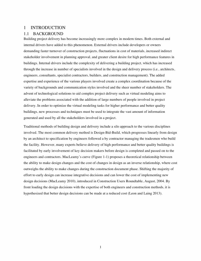
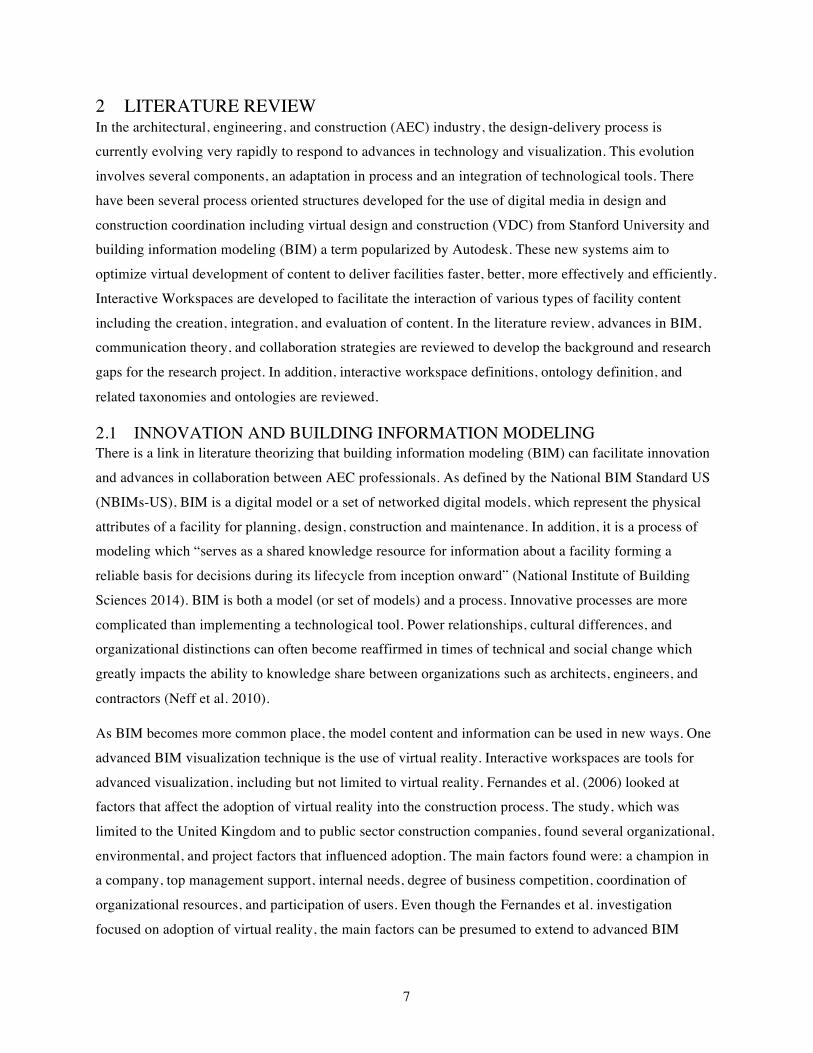
engineers and contractors. MacLeamy’s curve (Figure 1-1) proposes a theoretical relationship between the ability to make design changes and the cost of changes in design as an inverse relationship, where cost
outweighs the ability to make changes during the construction document phase. Shifting the majority of
effort to early design can increase integrative decisions and can lower the cost of implementing new
design decisions (MacLeamy 2010), introduced in Construction Users Roundtable, August, 2004. By front loading the design decisions with the expertise of both engineers and construction methods, it is
hypothesized that better design decisions can be made at a reduced cost (Leon and Laing 2013).
2
Figure 1-1: Most design effort occurs during the construction document phase (MacLeamy 2010).
There is ample debate in current literature as to how to achieve an integrative delivery. There are many methods using contractual agreements (i.e., relational contracts, bridging documents), informal
agreements (in the form of partnering agreements), lean delivery strategies (for faster production, e.g.,
just in time delivery), and value based procurement of design teams (to ensure expertise along with
project pricing). Given the complexity of the industry, research has only begun to investigate the actual process of integrating early expertise on project delivery outcomes. However widely understood the value
of integrating specialist information is, the ability to develop specific strategies is less understood by
practitioners and by researchers.
1.1.1 Rise in IT Applications for Design and Construction It is thought that advances in technology can support the integration of knowledge from various
disciplines and organizations, such as with building information modeling (BIM), virtual facility
prototyping, or virtual design and construction (VDC). For large to medium sized firms, BIM is becoming
a common practice for large and complex projects. However, current implementation of BIM strategies does not bridge knowledge gaps seen across organizational and disciplinary boundaries (Neff et al. 2010).
Interactive workspaces aim to create space for integrating the various expertise used in generating virtual
model content for integrative project delivery. To date, there is little research into the use of immersive
environments or interactive workspaces in industry practice (Kim et al. 2013). In spite of the lack in research, the architectural, engineering, and construction industry is beginning to adopt various complex,
collocated, multi-modal digital facilities to aid integrative and digital design (Khanzode 2012). These
types of facilities can help to develop the current adoption of effective uses with advance BIM implementation. This research is based on an understanding that there is wide variety of integrative
3
strategies and looks to investigate the various immersive workspace applications in use today, which can
enable multi-stakeholder and multi-disciplinary design decisions to optimize effective project delivery.
1.1.2 Interactive Workspaces Interactive workspaces (IWs) can include a variety of features: input, output, and participants. Input
devices can be haptic devices tracking motion of hand or head movement and controller devices such as
keyboard and mouse. Various types of output information are supported by display content and hardware content. Displays can include traditional monitor screens to headmounted-displays to large format
projected screens. This research focuses on interactive workspaces that utilize collocated multi-
stakeholder and multi-disciplinary knowledge in various use cases during the design delivery process.
Interactive workspaces are used within three distinct applications: collaborative, immersive, and flexible.
Collaborative interactive workspaces are those technology-enabled spaces that focus on creating collaborative practices within groups. This can be through simultaneous work or analysis, manipulation of
content, and displaying multi-modal content. In contrast, immersive interactive workspaces are those
spaces that enable a sense of immersion to participants as well as direct user interactivity. Given the
limited nature of processing location of participants in a digital environment and stereoscopic vision (e.g., tracking can occur on only one individual in a typical system), only a limited number of people can
effectively and comfortably participate simultaneously in high-end immersive interactive workspaces
(e.g., CAVE™ systems).
In addition, developers of interactive workspaces have integrated both the collaborative and immersive
features into flexible workspaces. These spaces can move between collaborative tasks and immersive tasks, with technological limitations such as networking, interactivity, and impact on sense of presence.
Depending on the workspace owner’s goals and objectives for using and implementing an interactive
workspace, different technological configurations exist. The application of facilities into collaborative
focused uses and immersive focused uses has its limitations as technology develops. There is cross over between technology which supports collaboration and technology which supports immersion, making this
designation difficult. In this research, the idea of how to categorize these facilities based on their features
and usage is explored in order to create a more robust definition of interactive workspaces.
1.1.3 Ontology of Interactive Workspaces An ontology of interactive workspaces and their use cases was developed to define the domain context
and develop the relationships to their entities and concepts. The research first surveys the current facilities
that support industry applications. A survey of a subset of facilities used in the last 10 years was selected
to generate the ontology of uses for developing this framework. Owners of specific facilities play various roles in the project delivery process (e.g., client, owner, contractor, architect, or consultant). These facility
owners were interviewed to provide information to outline the various projects that used the facility, how

4
they utilized it, and who participated. Literature review helped determined the use cases and to begin the
development of the ontology. Finally, the research culminates in the ontology of interactive workspaces and the elements of their usage for architectural, engineering, and construction (AEC) project teams. The
purpose of the ontology is to create a common language that can be used by researchers, practitioners, and
computer systems. The ontology was validated through two industry focus group meetings.
1.2 RESEARCH FOCUS To design a high performance facility, teams need to perform integrative tasks throughout the building process. However, teams cannot effectively work together without utilizing some form of workspace to
collaborate. Through the investigation of current practices of deploying interactive workspaces, project
teams can more effectively utilize these spaces in future collaborative tasks.
1.2.1 Research Goal The goal of this research is to aid in the AEC industry implementation of interactive and immersive
media-enabled spaces for multidisciplinary teams for complex and high performing buildings. In part, this
research aims to understand the technological feature-sets, and to better understand the usage and adoption of high-end display systems and workspaces, which are presently being deployed in the AEC
industry. Secondarily, the goal of this research is to develop a preliminary list of use cases and technical
attributes to begin to describe the needs of interactive workspaces to aid in specific activities. An axillary
goal of this research is to develop an initial list of use cases for interactive workspaces, so as to guide the
deployment of technology-enable spaces.
1.2.2 Research Objectives The research objectives have been developed to guide the research activities discussed in the
methodology. Given the lack of documented knowledge of uses of media-enabled spaces and their respective uses in industry applications, the research objectives are selected to explore the domain of
interactive workspaces.
RO1. Document interactive workspaces used in the AEC industry including characteristics and features.
RO2. Define the use cases of interactive workspaces in the AEC industry including processes and
characteristics.
RO3. Develop an ontology of interactive workspace functions, components and AEC industry use cases.
1.3 SCOPE OF WORK Interactive workspaces (IWs) are used in a variety of settings both within the AEC domain and outside of
the domain (e.g., psychology, neuroscience, military). Within the built environment, the majority of
research explores using IWs for proof-of-concept, training and educational activities. Most of those
applications will not fall into the scope of this research.

5
The criteria for interactive workspaces are as follows:
• Collaborative (2+ people) • Multidisciplinary • Applied (within the sector of Architecture, Engineering, and Construction) • Teams predominately collocated
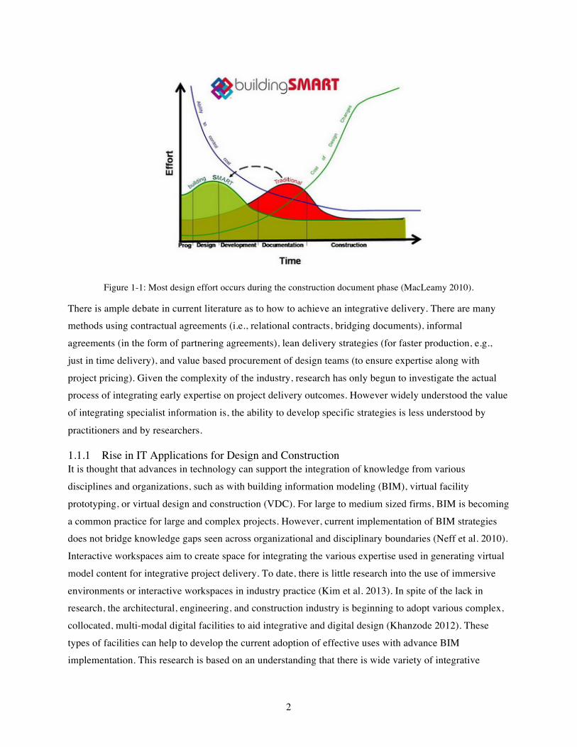
In addition to the above criteria, interactive workspaces have a variety of attributes, such as display size,
network computing systems, space layout system, level of immersion, and input systems. These scalar
elements have been used to further define the scope (Figure 1-2).
Figure 1-2: Defining Scope across Scalar Attributes of Interactive Workspaces
For display size, the scale runs from small to large displays, and this research focuses on facilities that
have a large display environment. Facilities must have large enough displays for multiple people to use and interact with digital content. In addition to display outputs, interactive workspaces have many types
of devices, which can connect and interact with the environment supported by the network computing
system. The scale of the network runs from a single computer to a ubiquitous computing environment.
For this research, focus is on facilities that have some medium to robust ubiquitous computing environment features, which implies that in addition to a large display environment there are other
connected devices within the facility, including personal computers, other devices, and potentially other
Classifying Interactive Workspaces
Display System
Space Layout
Level of Immersion
Input System
Network Computing System
Small Large
Single Computer Ubiquitous Computing
Single User 100+ Users
None Fully Immersive
Standard/Dual modal input Multiple/Custom Modal inputs
6
networked head mounted display devices. Since the criteria for scope includes collaborative collocation in
the space, the space layout system must fall in the middle of the spectrum from a single user to many users (e.g., presentation space), thus the space layout must support groups of people interacting with each
other as well as with digital content. The fourth and fifth attributes of an interactive workspace are the
level of immersion and the input system. These are scalar attributes that change depending on the facility
and their specific area of application, so no further refinement of the scope was performed in those areas. The scalar attributes of an interactive workspace allow for the focus of the criteria to be further refined yet
allow for flexibility in the definition and application of various technology and features deployed across
facilities.
This research focuses on institutions, companies, and professionals with experience using and/or
implementing IW solutions on AEC industry applications for multi-disciplinary, inter-organizational
teams. The scope was partially focused on facilities, industry, and use cases located in the United States, with some input from facilities, industry, and use cases internationally. The research also focuses on all
three areas of IW application: collaborative, immersive and flexible systems.
7
2 LITERATURE REVIEW In the architectural, engineering, and construction (AEC) industry, the design-delivery process is currently evolving very rapidly to respond to advances in technology and visualization. This evolution
involves several components, an adaptation in process and an integration of technological tools. There
have been several process oriented structures developed for the use of digital media in design and
construction coordination including virtual design and construction (VDC) from Stanford University and building information modeling (BIM) a term popularized by Autodesk. These new systems aim to
optimize virtual development of content to deliver facilities faster, better, more effectively and efficiently.
Interactive Workspaces are developed to facilitate the interaction of various types of facility content
including the creation, integration, and evaluation of content. In the literature review, advances in BIM, communication theory, and collaboration strategies are reviewed to develop the background and research
gaps for the research project. In addition, interactive workspace definitions, ontology definition, and
related taxonomies and ontologies are reviewed.
2.1 INNOVATION AND BUILDING INFORMATION MODELING There is a link in literature theorizing that building information modeling (BIM) can facilitate innovation
and advances in collaboration between AEC professionals. As defined by the National BIM Standard US
(NBIMs-US), BIM is a digital model or a set of networked digital models, which represent the physical
attributes of a facility for planning, design, construction and maintenance. In addition, it is a process of modeling which “serves as a shared knowledge resource for information about a facility forming a
reliable basis for decisions during its lifecycle from inception onward” (National Institute of Building
Sciences 2014). BIM is both a model (or set of models) and a process. Innovative processes are more
complicated than implementing a technological tool. Power relationships, cultural differences, and organizational distinctions can often become reaffirmed in times of technical and social change which
greatly impacts the ability to knowledge share between organizations such as architects, engineers, and
contractors (Neff et al. 2010).
As BIM becomes more common place, the model content and information can be used in new ways. One
advanced BIM visualization technique is the use of virtual reality. Interactive workspaces are tools for
advanced visualization, including but not limited to virtual reality. Fernandes et al. (2006) looked at factors that affect the adoption of virtual reality into the construction process. The study, which was
limited to the United Kingdom and to public sector construction companies, found several organizational,
environmental, and project factors that influenced adoption. The main factors found were: a champion in a company, top management support, internal needs, degree of business competition, coordination of
organizational resources, and participation of users. Even though the Fernandes et al. investigation
focused on adoption of virtual reality, the main factors can be presumed to extend to advanced BIM

8
visualization. The aspect of participation of users is of critical interest to usage of interactive workspaces
and thus their use cases for project teams.
2.2 COLLABORATION THEORY There are various collaboration theories that inform this research. The first is the use of media for
communication. In the first section, media communication theory is explored. The second section focuses
on how information processing impacts individuals and team performance. These theories make up the
basis for understanding how people utilize, understand, and digest digital information. Lastly, how these
theories inform interactive workspace usage is discussed.
2.2.1 Using Media for Collaboration In Media Synchronicity Theory (MST), tasks associated with two or more people communicating are defined as either conveyance (exchange of information) or convergence (agreed meaning and verification
of information). There are individual tasks associated with the collaborative task: information
transmission and information processing. Different media capabilities support various communication
processes. Specific digital media is not appropriate given the manner of rapid development in media tools, so it is important to define the feature sets of a given medium. The theory proposes that communication
performance is enhanced through the use of different media at different times, and that the use of media in
tandem or in succession may be necessary, e.g., face-to-face communication supported by documents,
models, etc., or a report first followed by a meeting. There is a cyclical relationship between an individual’s social structure and the media’s physical structure, and both influence how media is used. An
individual’s unfamiliarity with the tasks, individuals, and communication media also increase the need for
higher synchronicity of media. For example, if individuals are less familiar with tasks or individuals,
there is a greater need for media supporting higher synchronicity (Dennis et al. 2008). In the AEC industry, where project teams are created for brief periods of time and then disbanded, communication
performance is a key issue. Dennis et al. (2008) theorized that shared understanding is co-constructed by
the communication participants (or project team members). Communication performance is determined
by the team, and not by an individual. In addition, communication performance is only one factor that influences the choice of a given medium. The media synchronicity theory applies to communication
performance and not media choices, like previous theories it builds upon (e.g., Media Richness Theory).
2.2.2 Asynchronous Tasks vs. Synchronous Tasks The building sciences includes a complex set of project participants who carry specific knowledge for specific tasks within the building process, yet are dependent on the information of each other. Since a set
of highly specialized professional engineers are typically needed on a complex building project, the
ability to share and communicate complex information is necessary within the design and development of a project (Garcia et al. 2004). In the past these tasks have been tackled in an independent manner, creating
9
inconsistencies and rework in project development and delivery. As tasks become more interdependent,
information needs to flow in more than one direction or more rapidly, and synchronous communication tasks increase (i.e., in-person meetings). There have been some instances of infrastructure to support
extreme collaboration or synchronistic tasks for projects teams in the building and airline industries
(Garcia et al. 2004; Mark 2002). The methods of performing synchronistic tasks are still an open area of
research from a usability problem for computer scientists, such as with ubiquitous computing systems (Russell et al. 2005), to building engineers who explore implementation of collaborative workspaces in
the construction sector (Fernando 2008).
2.2.3 Collaboration in Interactive Workspaces Research in task and communication performance theories can highly impact the technology development for collaboration in interactive workspaces. Interactive workspaces are meant to be spaces where
synchronous tasks can be performed and convergence of shared meaning can be achieved with the aid of
multimodal content interaction. These theories focus on the performance of communication in a computer
mediated communication (CMC) context. Other areas of concern are individual performance in a human computer interaction (HCI) context, as the communication performance is only as good as the whole
team. Thus key aspects of collaboration in interactive workspaces include both the ability to perform
conveyance and convergence tasks in both an asynchronous and synchronous manner.
For example a typical meeting will include the following tasks: schedule a meeting; collect supporting
documents and models; review documents and models; identify issues; problem solve potential solutions; adjourn the meeting to rework documents and models; and reconvene to make final decisions. In this
example, individual tasks support the collaborative task of reaching a shared understanding and ultimately
making a final decision (which may or may not be a collaborative task). These individual tasks can
depend on the work of the collective tasks. Both conveying and converging occur during different steps of the collaborative tasks, ultimately helping the team explore and as a group understand all perspectives of
expertise involved. The use of an interactive workspace is meant to aid the convergence by allowing two
potential options (1) all information needed to be available is available synchronously with other media
and (2) information can be viewed in immersive ways, allowing for better analysis of design implications
for complex spatial interactions.
2.3 COLLOCATION THEORY Collaboration can be mediated through both physical and virtual collocation practices. Teams however
are still more effective at collaborating when physically collocated (Olson and Olson 2000). They proposed four key areas for distributive work: common ground (common language), collaboration
readiness, collaboration technologies readiness, and coupling of work. In 2014, Olson and Olson added a
fifth key area: organizational management. Depending on the expertise of the team members and their
10
relative comfort level with collaborative technologies, some teams do find virtual collocation effective
(Bjørn et al. 2014). However, the research of Bjørn et al. (2014) analyzed four instances of distributed teams working within a single organization in the software development industry. The variety of
technological expertise within the AEC industry, lack of common ground or common language among
team participants and clients, and highly coupled work indicates the AEC industry is not yet able to
effectively collaborate with virtual collocation technologies, and may be better suited to physical
collocation collaboration for certain tasks.
There is a vast amount of research and technology on computer supported cooperative work for distributive teams. This body of research focuses on complimenting that work by exploring technology
that aids collaboration in a single physical space or group of collocated spaces, which may include spaces
that support remote collaboration.
2.4 INTERACTIVE WORKSPACES DEFINITION Johanson and Fox (2004) defined interactive workspaces as technology-augmented team-project rooms
that are used by groups for collaborative problem solving. An interactive workspace has characteristics
based on human and technology factors. Human factors included bounded environment, human-centered
interaction and flexible reconfiguration, and human level performance needs. Technology factors included hardware, software and software platforms, changing environment with short and long term
changes (i.e., external device integration and space evolution) (Johanson and Fox 2004).
Fernando (2008) discussed future collaborative workspaces to include support for collocated or
geographically distributed participants, with tools and infrastructure dynamically configured to support
teams of individuals, for both collaborative and individual tasks.
Liston et al. (2000) discussed information workspaces as both physical and virtual workspaces, which may be collocated or virtually collocated. Four task categories were presented for supporting decision
making in these workspaces: descriptive tasks, explanative tasks, evaluative tasks, and predictive tasks.
Liston et al. (2000) hypothesized that these tasks are hierarchical, where spending more time on later
tasks, i.e., predictive tasks, could improve decision making for construction teams. In comparing teams reviewing project content in a 4D immersive virtual environment to traditional paper-based workspace
environments, teams spent more time on explanative tasks and less on descriptive tasks.
A related term to interactive workspaces is collaborative visualization. Isenberg et al. (2011) defines
collaborative visualization as “the shared use of computer-supported, (interactive) visual representations
of data by more than one person with the common goal of contribution to joint information processing
activities (Isenberg et al. 2011).” Although this definition focuses on the general act of visualizing
information collaboratively, it is closely aligned to the definition of interactive workspaces.
11
For this research, interactive workspaces have been defined as a physically located technology-‐‑ and
media-‐‑enabled project spaces facilitating human centered interaction and meaningful collaboration of
project team members utilizing heterogeneous devices and software featuring large format displays, for
content sharing and media viewing, and multi-‐‑modal interaction systems.
2.5 RELATED TAXONOMIES Milgram and Kishino (1994) presented a taxonomy of mixed reality visual displays, a three dimensional continuum of virtuality as displayed in 6 classes of mixed reality. The taxonomy presents an efficient
classification framework based on whether the user primarily focused on virtual content, intended to feel
present in the environment, viewed directly or indirectly the real world, and viewed the environment
scaled to the real world. Papadopoulos et al. (2014) predicts the use of an array of augmented, mixed, and virtual reality will become more ubiquitous in use with human-to-human communication, yet are
dependent on the ability of researchers to pursue a coordinated effort to develop empirical evaluation of
interaction systems.
Laha and Bowman (2012) identified two limitations of research in immersive facilities. They proposed
the need for researchers to develop a component level comparison of facilities and a task taxonomy to address these limitations in the research of facilities. Even though Laha and Bowman’s paper was targeted
for a specific use case (volume data visualization), the task taxonomy and research methodology proposed
were not domain specific and are useful in many fields such as visualization, data analysis, medicine,
psychology, paleontology, archaeology, architecture, engineering, and construction. Their work outlined a need for a user task taxonomy, however only outlined six preliminary task categories: search and counting
tasks, relative 3D position/orientation judgments, shape or density estimation, path-following, pattern
identification, and shape description. Further research refined this task taxonomy specifically for visual
analysis research with healthcare professionals (Laha et al. 2015).
2.6 ONTOLOGY DEFINITION Ontology development has been used within many disciplines to describe, define terms, and categorize
domains, especially noted in recent times in the field of information sciences. The classical definition of
an ontology is the “systematic explanation of existence” (Gómez-Pérez 1999). This definition, while
widely referred to, is not specific about how an ontology differs from defining or categorizing systems.
In the information sciences domain, an ontology has been defined as “an explicit representation of
conceptualization” (Gruber 1995). Gruber’s definition gives more insight into generating an ontology of a
domain, but is still open to a variety of interpretations.
A further definition of an ontology has been given as “a formal explicit description of the concepts in a
domain or discourse, properties of each concept describing various features and attributes of the concept,
12
and restrictions on slots” (Noy and McGuinness 2001). In this definition the components which are
essential for an ontology are exposed: concepts, properties, features, and attributes. Essentially, an ontology includes concepts (their subsequent properties or attributes) and the relationship with other
concepts and sub-concepts. An ontology is a combination of a dictionary and a taxonomy within a
specified domain including an explicit set of definitions, relationships and categorization.
For an interactive workspaces ontology, this general ontology definition means that the concepts and
terms involved in an interactive workspace are given explicit definitions, relationships, and
categorizations. An interactive workspace ontology includes the activities that the workspace is used for, the people involved, the technology deployed, and the characteristics and sub-relationships involved. For
the scope of this research, how the ontology relates to existing literature on meeting ontologies or
business models was not explored, however could be a future area of work. The following section
describes current related ontologies to the domain of interactive workspaces.
2.7 RELATED ONTOLOGIES Garcia et al. (2004) presented a project, organization, and process (POP) ontology for what they called
‘extreme’ collaboration. By comparing the POP ontology to other examples of distributed teams in other
industries, the POP ontology for collaboration was developed for use with rapid prototyping in use with virtual design and construction (VDC). Their ontology was focused on project prototyping for specific
tasks, virtual entities used within a project meeting setting, and their relation to the project and
organization usages.
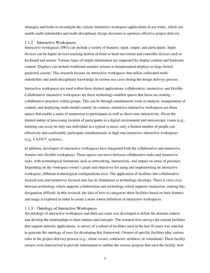
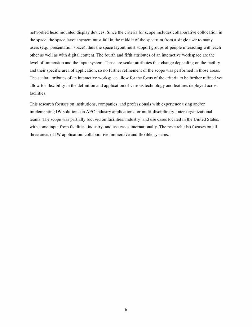
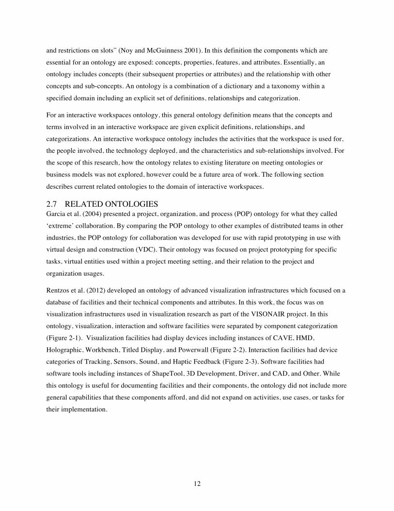
Rentzos et al. (2012) developed an ontology of advanced visualization infrastructures which focused on a
database of facilities and their technical components and attributes. In this work, the focus was on visualization infrastructures used in visualization research as part of the VISONAIR project. In this
ontology, visualization, interaction and software facilities were separated by component categorization
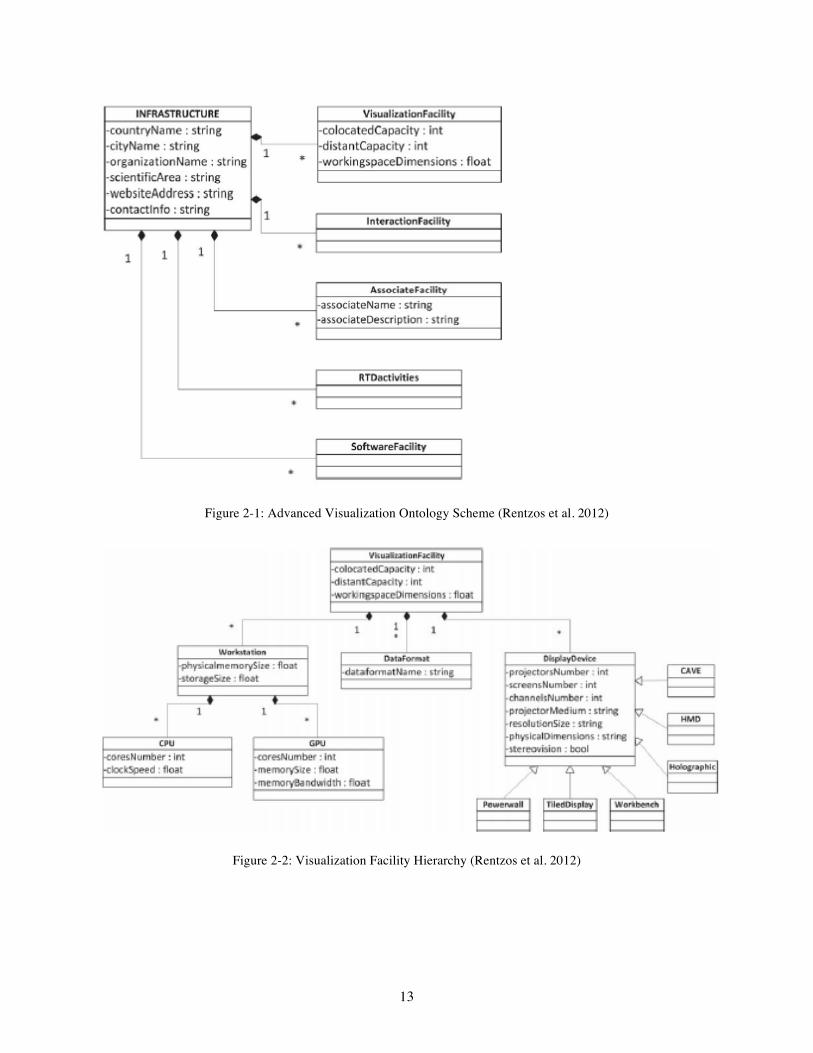
(Figure 2-1). Visualization facilities had display devices including instances of CAVE, HMD,
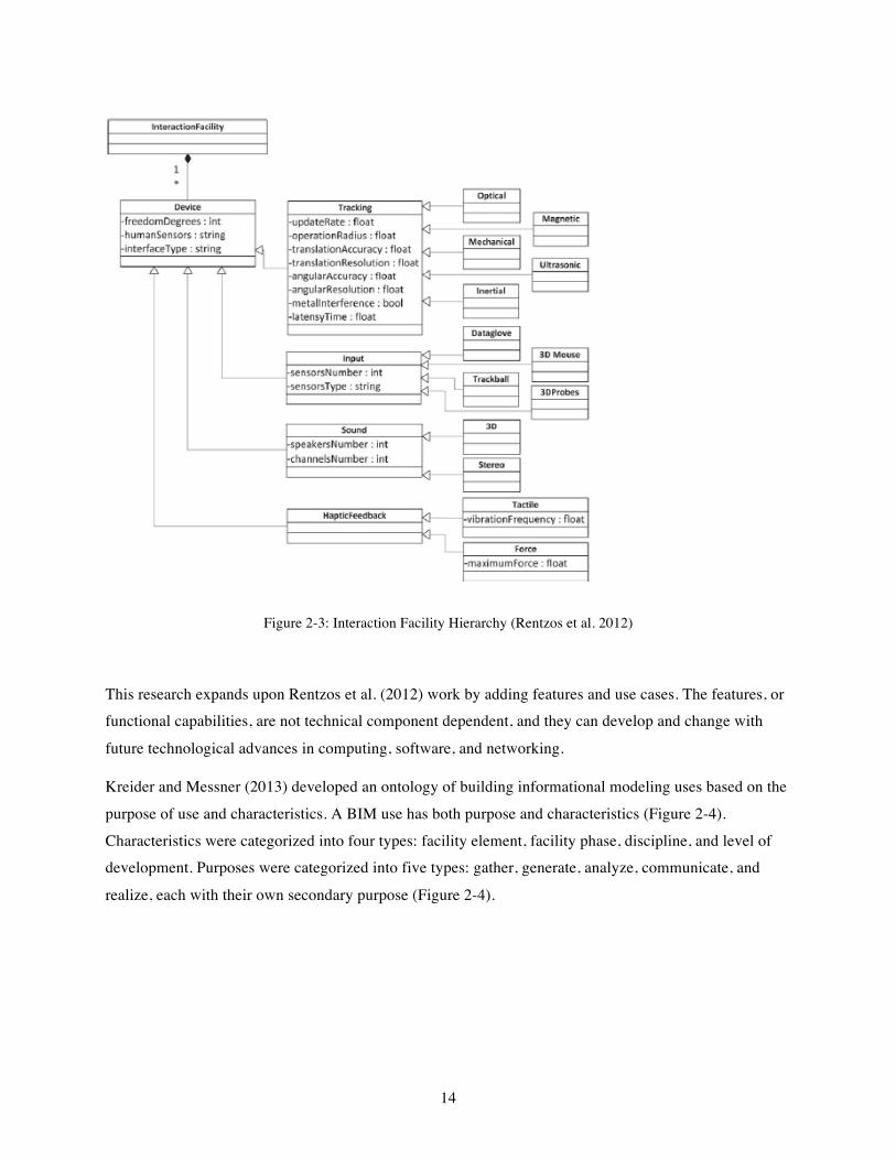
Holographic, Workbench, Titled Display, and Powerwall (Figure 2-2). Interaction facilities had device categories of Tracking, Sensors, Sound, and Haptic Feedback (Figure 2-3). Software facilities had
software tools including instances of ShapeTool, 3D Development, Driver, and CAD, and Other. While
this ontology is useful for documenting facilities and their components, the ontology did not include more
general capabilities that these components afford, and did not expand on activities, use cases, or tasks for
their implementation.
13
Figure 2-1: Advanced Visualization Ontology Scheme (Rentzos et al. 2012)
Figure 2-2: Visualization Facility Hierarchy (Rentzos et al. 2012)
14
Figure 2-3: Interaction Facility Hierarchy (Rentzos et al. 2012)
This research expands upon Rentzos et al. (2012) work by adding features and use cases. The features, or functional capabilities, are not technical component dependent, and they can develop and change with
future technological advances in computing, software, and networking.
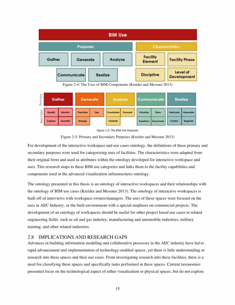
Kreider and Messner (2013) developed an ontology of building informational modeling uses based on the
purpose of use and characteristics. A BIM use has both purpose and characteristics (Figure 2-4).
Characteristics were categorized into four types: facility element, facility phase, discipline, and level of development. Purposes were categorized into five types: gather, generate, analyze, communicate, and
realize, each with their own secondary purpose (Figure 2-4).
15
Figure 2-4: The Uses of BIM Components (Kreider and Messner 2013)
Figure 2-5: Primary and Secondary Purposes (Kreider and Messner 2013)
For development of the interactive workspace and use cases ontology, the definitions of these primary and
secondary purposes were used for categorizing uses of facilities. The characteristics were adapted from
their original form and used as attributes within the ontology developed for interactive workspace and uses. This research maps to these BIM use categories and links them to the facility capabilities and
components used in the advanced visualization infrastructures ontology.
The ontology presented in this thesis is an ontology of interactive workspaces and their relationships with
the ontology of BIM use cases (Kreider and Messner 2013). The ontology of interactive workspaces is
built off of interviews with workspace owners/managers. The uses of these spaces were focused on the uses in AEC Industry, or the built environment with a special emphasis on commercial projects. The
development of an ontology of workspaces should be useful for other project based use cases in related
engineering fields, such as oil and gas industry, manufacturing and automobile industries, military
training, and other related industries.
2.8 IMPLICATIONS AND RESEARCH GAPS Advances in building information modeling and collaborative processes in the AEC industry have led to
rapid advancement and implementation of technology-enabled spaces, yet there is little understanding or
research into these spaces and their use cases. From investigating research into these facilities, there is a need for classifying these spaces and specifically tasks performed in these spaces. Current taxonomies
presented focus on the technological aspect of either visualization or physical spaces, but do not explore

16
use cases within the facilities. Current ontologies of building information modeling uses explored the
purpose of uses, but do not link these uses to the technology and visualization techniques currently available. Exploring and documenting what project teams are doing and what feature sets are being used
are the first steps into understanding future areas of research including effective deployment,
implementation, and research of technology to aid in collaborative tasks and advanced analytical
visualization.
17
3 METHODOLOGY To capture current adoption of technology and media-enable spaces and their respective use cases in the AEC Industry, an exploratory research methodology was used. The research has been broken down into
four steps. The first three steps were investigation and data collection. The final two steps were part of the
analysis and ontology development activities. The first step was to develop an understanding of the
breadth of interactive workspaces that exist and being used within the scope defined in Chapter 1.3. The second step was to develop an understanding of the technical attributes and use cases of the interactive
workspaces through interviews with owners and managers of these facilities. The third step was to
develop a categorization system for interactive workspaces and their respective use cases through the
development of the ontology. The final step was to validate the ontology with industry members. The following sections will introduce the research methods and describe the research process and analysis of
these four steps.
This research is interdisciplinary in nature, pulling research methodology from visualization and project
management. The methodologies deployed in this research are literature review and semi-structured
interviews. The semi-structured interviews were with owners and managers of interactive workspaces.
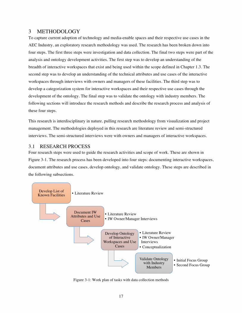
3.1 RESEARCH PROCESS Four research steps were used to guide the research activities and scope of work. These are shown in
Figure 3-1. The research process has been developed into four steps: documenting interactive workspaces,
document attributes and use cases, develop ontology, and validate ontology. These steps are described in
the following subsections.
Figure 3-1: Work plan of tasks with data collection methods
Develop List of Known Facilities • Literature Review
Document IW Attributes and Use
Cases• Literature Review• IW Owner/Manager Interviews
Develop Ontology of Interactive
Workspaces and Use Cases
• Literature Review• IW Owner/Manager Interviews
• Conceptualization
Validate Ontology with Industry
Members
• Initial Focus Group• Second Focus Group
18
3.1.1 Step One: Develop List of Known Facilities The initial step in this research is to document the interactive workspaces being used in application for the
AEC industry. Documentation began with known facilities, and has expanded through review of the
literature (archival and non-archival) and through interviews with owners and managers of these facilities.
A combination of efforts were used in development of this list of known facilities including efforts with the members of the Consortium for Building Energy Innovation (CBEI) 2014-2015 Subtask 3.3
researchers and research assistants. The list of interactive workspaces was filtered by the scope of work
and definition of an interactive workspace, which are presented in Chapter 1.3 and Chapter 2.4,
respectively. There are a number of facilities that exist but may not be found in this investigation. The scope of this research does not intend to create a comprehensive list of interactive workspaces, however it
does aim to gain an understanding of the breadth of workspaces currently being deployed.
3.1.2 Step Two: Document IW Attributes and Use Cases Of the facilities documented in step one, managers and owners were contacted for interviews about their
space and how they are used. The goal of owner/manager interviews was to gain an understanding of the
technical and physical attributes of the workspaces, goals for creating the space, setup, and current
general practices. Managers can be owner representatives, technical specialists, and service providers. These individuals had expertise with using interactive workspaces for AEC applications, development
and implementation process, and/or designing and building the interactive workspace itself.
Documentation included attributes and technical capabilities available in the space and how AEC project
teams use the space. The interviews were semi-structured. For information on the development of the
questions, refer to Section 3.2. For protocol and question documentation refer to Appendix B.
3.1.3 Step Three: Develop Ontology of Interactive Workspaces and Use Cases Once both the technical attributes of interactive workspaces and their use cases have been defined and
documented, relationships between feature sets and their use to support specified use case activities was explored. The analysis included development of a database of workspaces and their respective use cases.
An exploratory investigation occurred to develop an ontology defining key elements, relationships, key
attributes, and categories between current user applications of these technology-enabled spaces. The conceptualization phase used the use cases reported, facility capabilities reported, facility components,
and purposes and characterizations from the Uses of BIM (Kreider and Messner 2013) to develop initial
entity relationship diagrams. A second development phase occurred after initial validation to expand the
ontology with attributes and further refinement of categorizations using input from industry members and review of the ontology of Advanced Visualization Infrastructures (Rentzos et al. 2012). For more
information on ontology development see Section 3.3.
19
3.1.4 Step Four: Validate Ontology with Industry Members The fourth step was to validate the ontology with industry members. Two focus group sessions were
conducted. The first, initial, validation occurred with architects, engineers, and software vendors. The
second validation occurred with construction managers. These sessions included an introduction of the
ontology developed from step three, with subsequent revisions between validation focus groups. A
summary of discussion and recommendations from each session is provided in Section 3.4.
3.2 INTERVIEW PROCESS AND PROTOCOL The interview protocol was created through an iterative review process. Initial questions for interactive
workspace owners and managers were generated and tested in a series of 4 test runs with 4 individuals familiar with the same facility. A panel of four researchers additionally reviewed the interview questions.
The detailed questions are meant as a semi-structured interview, which is dependent on the interviewee’s
experience and type of interactive workspace. A protocol was developed including pre-interview and post
interview steps. For the protocol and interview questions see Appendix B.
Interviewees were identified via known facilities and known experts in utilizing, managing, and/or operating these facilities. Recruitment included emailing potential interviewees, describing the purpose of
the study, and obtaining informed consent before proceeding with the interviews.
Twelve interviews were conducted with thirteen manager representatives of eleven interactive
workspaces. Interviews continued to be conducted until all sectors of owner types and facilities types
were adequately represented. Owner types included academic, industry, vendor, and government. Facilities represented in the interview pool had an application focus in collaboration technology,
immersive technology, and/or flexible technology systems and infrastructure.
3.3 ONTOLOGY DEVELOPMENT The ontology was developed based on investigation of interactive workspaces through survey of
literature, survey of publicly available use cases, and interviews with interactive workspace owners. The information gathered through the literature review, surveying known facilities, and interviews with
manager representatives were used to understand the domain of interactive workspaces and AEC Industry
use cases. These initial concepts were developed into entities and relationships. Further refinement of the
key elements and entities produced attributes for entities and categorization for entities. IDEF1X notation
conventions were used (for conventions see Bruce 1992).
3.3.1 Ontology Development Steps Ontology development can follow many different methodological approaches (Jones et al. 1998). For this research, the main steps roughly followed the Methontology approach to development. Methontology was
initially described in (Gómez-Pérez et al. 1996) and later refined in (Fernandez et al. 1997), and is a
20
method used throughout the life-cycle of an ontology. The focus of this research was on the steps related
to development of ontologies: specification, knowledge acquisition, conceptualization, integration,
implementation, and evaluation.
The phases used in the creation of this ontology are as follows:
Phase 1: Specification (define domain and scope): The development of this ontology is based on exploratory research in the domain of interactive workspaces within the AEC domain. Domain
and scope were further defined in Chapters 1.3 and 2.4. The proposed usage is for usage of
interactive workspaces, implementation (planning) the usage of interactive workspaces,
analyzing domain knowledge, and researching and documenting use cases for collaborative teams. Future development of this ontology includes addition of future features and components
as well as development of tasks used in use cases.
Phase 2: Knowledge Acquisition: Through surveying literature and publicly available documentation of
facilities, facilities used in AEC industry application areas were documented. Several facilities
were selected to provide more detailed information on their facilities through semi-structured interviews with owners and managers. Expert owner/manager interviews were performed from
a variety of owner types similar in representation to the owner types in the population of
documented facilities.
Phase 3: Conceptualization: In the conceptualization phase, the main entities were defined as interactive
workspaces, and the meetings or workshops that occur in them. Use cases were defined as a link between a general meeting/workshop, which AEC team members regularly have, and the
interactive workspace facilities. Other terms investigated as relating to either meetings or
interactive workspaces were defined, and initial relationship diagrams were developed. Through
this conceptualization, meetings and interactive workspaces were deemed as two related domains, where the cross-section of elements experts used to describe usage of these facilities
were used to develop the relationships, attributes, and categorization of terms.
Phase 4: Integration: To integrate this ontology with the developments of other ontologies, definitions
developed in The Uses of BIM (Kreider and Messner 2013) were used for categorizing use
cases of facilities. For facilities, the related Ontology of Advanced Visualization Infrastructures
(Rentzos et al. 2012) was used for differentiating between attributes and entities.
Phase 5: Implementation: The ontology was formally represented in IDEF1X, depicting entities,
relationships, attributes, and instances.
21
Phase 6: Evaluation: Verification of the ontology’s correctness and validation of the completeness,
inconsistencies, and redundancies occurred through two focus group sessions with industry members. The initial session occurred shortly after the initial ontology was developed by
generating initial relationships and initial categorizations. The second session occurred shortly
after categories were refined, instances were developed, and initial attributes were assigned.
Phase 7: Documentation: The initial and second draft of the ontology are documented in Appendix D.
The final ontology is documented in Chapter 5. A definition list is documented in Appendix A.
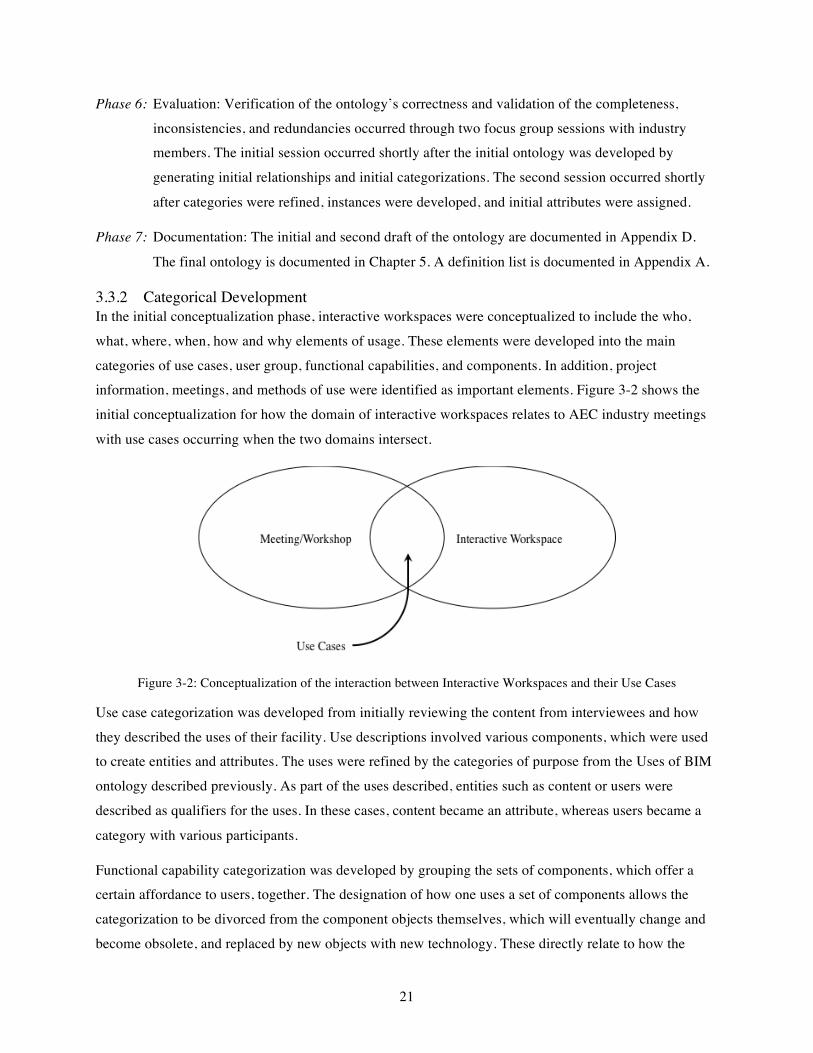
3.3.2 Categorical Development In the initial conceptualization phase, interactive workspaces were conceptualized to include the who,
what, where, when, how and why elements of usage. These elements were developed into the main
categories of use cases, user group, functional capabilities, and components. In addition, project information, meetings, and methods of use were identified as important elements. Figure 3-2 shows the
initial conceptualization for how the domain of interactive workspaces relates to AEC industry meetings
with use cases occurring when the two domains intersect.
Figure 3-2: Conceptualization of the interaction between Interactive Workspaces and their Use Cases
Use case categorization was developed from initially reviewing the content from interviewees and how
they described the uses of their facility. Use descriptions involved various components, which were used to create entities and attributes. The uses were refined by the categories of purpose from the Uses of BIM
ontology described previously. As part of the uses described, entities such as content or users were
described as qualifiers for the uses. In these cases, content became an attribute, whereas users became a
category with various participants.
Functional capability categorization was developed by grouping the sets of components, which offer a certain affordance to users, together. The designation of how one uses a set of components allows the
categorization to be divorced from the component objects themselves, which will eventually change and
become obsolete, and replaced by new objects with new technology. These directly relate to how the
22
users use the facility, such as model visualization, where the GPU isn’t specified, only that a model
visualization needs to be capable.
Component categorization was developed by initially listing all of the pieces and parts of an interactive
workspace, including space infrastructure. These elements were then grouped by similarity: infrastructure elements became spatial components, hardware components were group together, and software
components were grouped together. Software used in an interactive workspace had a second
categorization: the function. The software function was grouped as application, development, or system
software.
3.4 ONTOLOGY VALIDATION The ontology developed was validated through two separate industry focus groups. The validation
process included having representatives from architecture, engineering and construction managers. The
focus groups went through a process of displaying and walking through the current iteration of the ontology with some explanation of a basic overview of the entity relationship diagrams. Questions were
fielded on organization of the ontology. Three thematic questions were asked of participants about any
gaps in content in the ontology, any use cases they would like to see in the ontology, and any future
scenarios for using interactive workspaces (technology and use cases). The paper handouts given for each
validation session are included in Appendix D.
3.4.1 Focus Group Procedure The following steps were part of the focus group procedure and protocol.
(1) Identify group gathering of AEC industry professionals.
(2) Ask permission of organizers to host a breakout session.
(3) Participants were asked to voluntarily attend a breakout session dedicated to reviewing and
commenting on the ontology of interactive workspaces.
(4) Researcher and group conduct focus group:
(a) Researcher distributed printouts of ontology
(b) Researcher gives overview of ontology
(c) Researcher asks three discussion generating questions
(5) Researcher reviews comments and documents recommended changes.
(6) Follow up with participants for any additional comments.
3.4.2 Focus Group Questions Three questions were developed to guide the conversation of the ontology. The first was aimed at identifying any missing elements in the ontology. The second was aimed at investigating current use
23
cases and how they would fit into the ontology. The third was aimed at investigating what other ways
people see future applications within these types of facilities and whether they fit into the ontology.
Q1. Are there any concepts you would like to see in this ontology?
Q2. What other use cases can you think of and do they fit within this ontology?
Q3. Can you think of any future scenarios for using an interactive workspace?
3.4.3 Initial Validation For initial validation, a drafted ontology was presented to architects and engineers as part of a voluntary
session in a workshop on Virtual Reality Applications for the AEC Industry. There were 10 participants
from three architectural firms, one engineering firm, and one software vendor. The session lasted one
hour. It began with a presentation of the ontology, the major relationships and entities, with a handout of the presented material. Secondly a third party organizer of the workshop guided the discussion of the
work with three thematic questions developed by the researcher. The researcher fielded questions
pertaining to clarifications and content questions.
The major outcomes from the initial validation with ten industry members were formatting and the
cyclical nature of collaborative activities. For formatting, the group found it difficult to follow the connections between elements and felt a more fluid mind-mapping format would be helpful for industry
understanding. Participants found the designation of task type into generating and visualize/analyze
useful, and related these concepts to working (generating) and presenting (visualize/analyze) tasks, which
are used throughout the cycle of design. Although the ontology meant to convey how teams use the space, it may support different aspects of the design cycle through variety of features in the facility. The cyclical
nature of the building process was not directly addressed in the ontology, however should be kept in mind
by organizations and researchers when planning implementation.
Generally, participants found the ontology helpful for planning to use a facility and for planning to
implement one in their own organization. Future ideas for how one could use these types of facilities included connecting the facility to the job-site activities through leveraging drone technology, augmented
and mixed reality, and conferencing technology.
3.4.4 Second Validation For the second validation, a revised ontology was presented to construction managers as part of a voluntary session in an industry focused roundtable on research in the construction industry. There were
eleven participants from eight different construction management firms. The session lasted one hour. It
began with a brief introduction of the topic of interactive workspaces followed by a walkthrough of the
ontology, which was presented in handout form. A discussion was fielded by the researcher about
24
questions participants had about the ontology, and then the three thematic questions were asked of the
participants. A third party note-taker was present in the session.
The major outcomes from the second validation with eleven industry members were a discussion of
project vs. client use cases and the identification of a developer as an important user. In order to support the use of a high-tech facility, the participants recommended a ‘developer’ user to be added to the users of
the interactive workspace. For the discussion of project vs. client use cases, there were two perspectives
of the value of using an interactive workspace. These two perspectives were either client focused or
project team focused. Some saw the value of an interactive workspace specifically in conveying and communicating information with stakeholders and clients. Others saw the value of an interactive
workspace specifically in the technology access and availability to project team members. These
perspectives are important for understanding the content purpose and can be compared with the internal
and external team member designation. The ontology is comprised of use cases that can be either client or project focused; yet ultimately it is up to the organization or the project team to determine what the focus
should be for a given project. The technology used should be easy to access for clients and available for
both large and small budget projects so as to not leave a technology gap between project types.
No participants voiced concerns with the revised formatting. In addition, they explained they performed
all the use cases documented, but not necessarily in an interactive workspace. They recommended the goal be the first item that drives the choice of an interactive workspace and that individual users dictate
the choice of technology.
25
4 SURVEY OF INTERACTIVE WORKSPACES During documentation of interactive workspaces, 84 interactive workspaces were found across sectors of architecture, engineering, construction, military, science and technology. Of these facilities, 49 were
found to have been used in some application related to the architecture, engineering, or construction
applications areas. These facilities have a collection of different qualities, which have been roughly
translated into three types of workspaces: immersive, interactive, and flexible workspaces. Immersive facilities are facilities that have a focus on immersive capabilities, including presence and a sense of
immersion. Interactive facilities are facilities that have a focus on interactive and multi-modal content,
including tactile interaction and multi-viewing of content. Flexible facilities are facilities that have
abilities to perform both immersive and interactive functionalities.
These facilities are part of approximately 60 organizations. Of these organizations, 35 of them used their interactive workspaces for some uses in the architecture, engineering, or construction industries. Spaces
are found in organizations categorized as Industry, Government, Vendor, and Academia. Industry owners
include vendors, owners, and AEC professionals. Government owners include United States National
Labs or Government funded research centers. Vendor owners include organizations that supply or construct interactive workspaces. Academia owners include interdisciplinary labs, Architecture,
Engineering, and Computer Science Facilities. Auxiliary industry owner types include manufacturing
(automobile, aircraft, and military) and technology sectors where some exemplary facilities exist.
4.1 DEMOGRAPHICS OF INTERACTIVE WORKSPACES For each of the documented interactive workspaces, the demographics of their application areas, their
organization type, and their location were investigated. Each section below describes each of these areas.
4.1.1 Application Demographics of Interactive Workspaces Through investigating publicly available information on known facilities, the purposes published on publicly available sources were documented. Each use was mapped with the Uses of BIM five categories:
gather, generate, communicate, analysis, and realize. A sixth category was utilized to document
educational use cases, which were either education or training use cases. This additional category was
deemed an organizational use case, because of its primarily non-project based nature. For the 84
interactive workspaces, 126 uses were categorized as AEC industry uses.
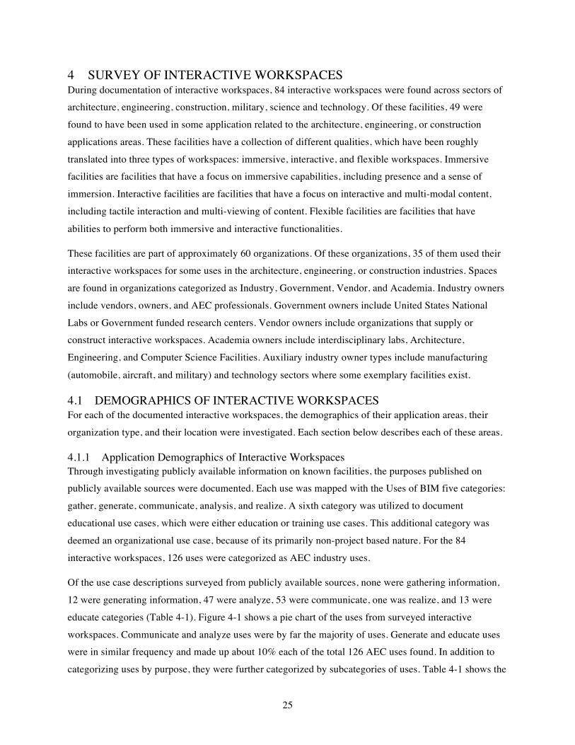
Of the use case descriptions surveyed from publicly available sources, none were gathering information,
12 were generating information, 47 were analyze, 53 were communicate, one was realize, and 13 were
educate categories (Table 4-1). Figure 4-1 shows a pie chart of the uses from surveyed interactive
workspaces. Communicate and analyze uses were by far the majority of uses. Generate and educate uses were in similar frequency and made up about 10% each of the total 126 AEC uses found. In addition to
categorizing uses by purpose, they were further categorized by subcategories of uses. Table 4-1 shows the
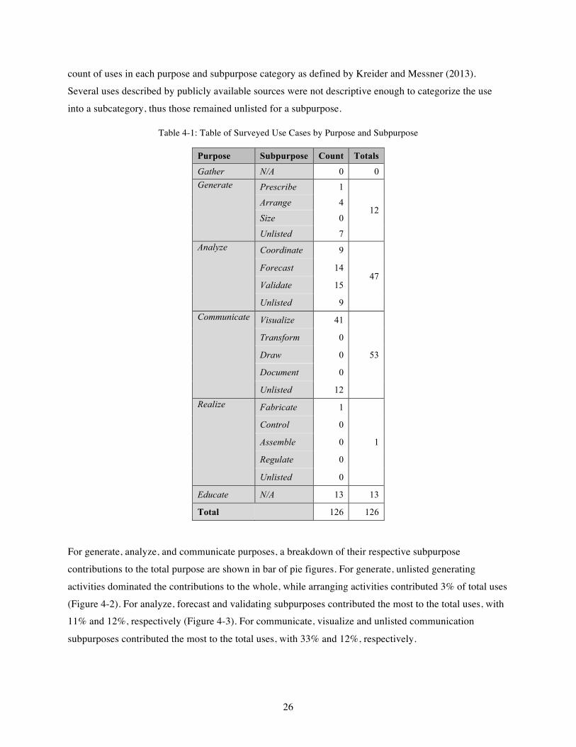
26
count of uses in each purpose and subpurpose category as defined by Kreider and Messner (2013).
Several uses described by publicly available sources were not descriptive enough to categorize the use
into a subcategory, thus those remained unlisted for a subpurpose.
Table 4-1: Table of Surveyed Use Cases by Purpose and Subpurpose
Purpose Subpurpose Count Totals
Gather N/A 0 0 Generate Prescribe 1
12 Arrange 4
Size 0
Unlisted 7 Analyze Coordinate 9
47 Forecast 14
Validate 15
Unlisted 9 Communicate Visualize 41
53
Transform 0
Draw 0
Document 0
Unlisted 12 Realize Fabricate 1
1
Control 0
Assemble 0
Regulate 0
Unlisted 0
Educate N/A 13 13
Total 126 126
For generate, analyze, and communicate purposes, a breakdown of their respective subpurpose
contributions to the total purpose are shown in bar of pie figures. For generate, unlisted generating
activities dominated the contributions to the whole, while arranging activities contributed 3% of total uses
(Figure 4-2). For analyze, forecast and validating subpurposes contributed the most to the total uses, with 11% and 12%, respectively (Figure 4-3). For communicate, visualize and unlisted communication
subpurposes contributed the most to the total uses, with 33% and 12%, respectively.
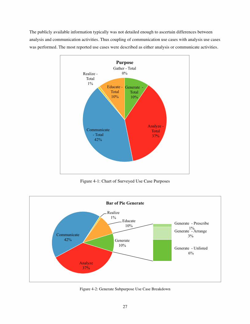
27
The publicly available information typically was not detailed enough to ascertain differences between
analysis and communication activities. Thus coupling of communication use cases with analysis use cases
was performed. The most reported use cases were described as either analysis or communicate activities.
Figure 4-1: Chart of Surveyed Use Case Purposes
Figure 4-2: Generate Subpurpose Use Case Breakdown
Gather - Total 0%
Generate - Total 10%
Analyze - Total 37%
Communicate - Total 42%
Realize - Total 1%
Educate - Total 10%
Purpose
Analyze 37%
Communicate 42%
Realize 1%
Educate 10% Generate - Prescribe
1% Generate - Arrange
3%
Generate - Unlisted 6%
Generate 10%
Bar of Pie Generate
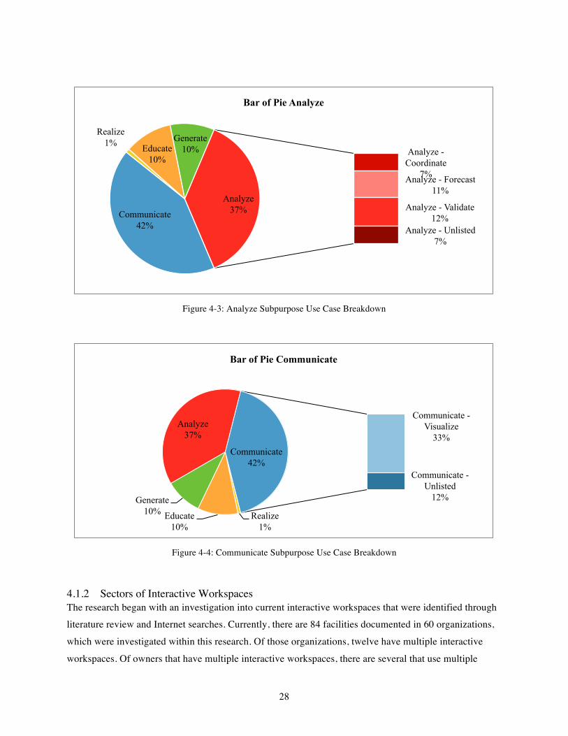
28
Figure 4-3: Analyze Subpurpose Use Case Breakdown
Figure 4-4: Communicate Subpurpose Use Case Breakdown
4.1.2 Sectors of Interactive Workspaces The research began with an investigation into current interactive workspaces that were identified through literature review and Internet searches. Currently, there are 84 facilities documented in 60 organizations,
which were investigated within this research. Of those organizations, twelve have multiple interactive
workspaces. Of owners that have multiple interactive workspaces, there are several that use multiple
Communicate 42%
Realize 1% Educate
10%
Generate 10% Analyze -
Coordinate 7% Analyze - Forecast
11%
Analyze - Validate 12%
Analyze - Unlisted 7%
Analyze 37%
Bar of Pie Analyze
Realize 1%
Educate 10%
Generate 10%
Analyze 37%
Communicate - Visualize
33%
Communicate - Unlisted
12%
Communicate 42%
Bar of Pie Communicate
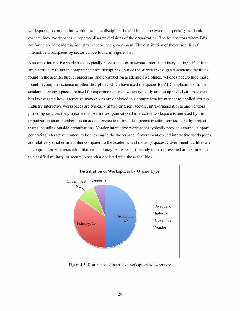
29
workspaces in conjunction within the same discipline. In addition, some owners, especially academic
owners, have workspaces in separate discrete divisions of the organization. The four sectors where IWs are found are in academia, industry, vendor, and government. The distribution of the current list of
interactive workspaces by sector can be found in Figure 4-5.
Academic interactive workspaces typically have use cases in several interdisciplinary settings. Facilities
are historically found in computer science disciplines. Part of the survey investigated academic facilities
found in the architecture, engineering, and construction academic disciplines, yet does not exclude those
found in computer science or other disciplines which have used the spaces for AEC applications. In the academic setting, spaces are used for experimental uses, which typically are not applied. Little research
has investigated how interactive workspaces are deployed in a comprehensive manner to applied settings.
Industry interactive workspaces are typically in two different sectors, intra-organizational and vendors
providing services for project teams. An intra-organizational interactive workspace is one used by the organization team members, as an added service to normal design/construction services, and by project
teams including outside organizations. Vendor interactive workspaces typically provide external support
generating interactive content to be viewing in the workspace. Government owned interactive workspaces
are relatively smaller in number compared to the academic and industry spaces. Government facilities are in conjunction with research initiatives, and may be disproportionately underrepresented at this time due
to classified military, or secure, research associated with those facilities.
Figure 4-5: Distribution of interactive workspaces by owner type
Academic, 42
Industry, 29
Government, 8
Vendor, 5
Distribution of Workspaces by Owner Type
Academic
Industry
Government
Vendor
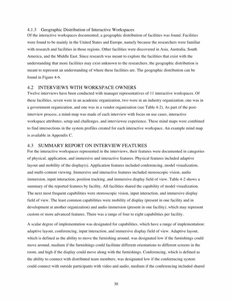
30
4.1.3 Geographic Distribution of Interactive Workspaces Of the interactive workspaces documented, a geographic distribution of facilities was found. Facilities
were found to be mainly in the United States and Europe, namely because the researchers were familiar
with research and facilities in those regions. Other facilities were discovered in Asia, Australia, South
America, and the Middle East. Since research was meant to explore the facilities that exist with the understanding that more facilities may exist unknown to the researchers, the geographic distribution is
meant to represent an understanding of where these facilities are. The geographic distribution can be
found in Figure 4-6.
4.2 INTERVIEWS WITH WORKSPACE OWNERS Twelve interviews have been conducted with manager representatives of 11 interactive workspaces. Of
these facilities, seven were in an academic organization, two were in an industry organization, one was in
a government organization, and one was in a vendor organization (see Table 4-2). As part of the post-
interview process, a mind-map was made of each interview with focus on use cases, interactive workspace attributes, setup and challenges, and interviewee experience. These mind maps were combined
to find intersections in the system profiles created for each interactive workspace. An example mind map
is available in Appendix C.
4.3 SUMMARY REPORT ON INTERVIEW FEATURES For the interactive workspaces represented in the interviews, their features were documented in categories
of physical, application, and immersive and interactive features. Physical features included adaptive
layout and mobility of the display(s). Application features included conferencing, model visualization,
and multi-content viewing. Immersive and interactive features included stereoscopic vision, audio immersion, input interaction, position tracking, and immersive display field of view. Table 4-2 shows a
summary of the reported features by facility. All facilities shared the capability of model visualization.
The next most frequent capabilities were stereoscopic vision, input interaction, and immersive display
field of view. The least common capabilities were mobility of display (present in one facility and in development at another organization) and audio immersion (present in one facility), which may represent
custom or more advanced features. There was a range of four to eight capabilities per facility.
A scalar degree of implementation was designated for capabilities, which have a range of implementation:
adaptive layout, conferencing, input interaction, and immersive display field of view. Adaptive layout,
which is defined as the ability to move the furnishing around, was designated low if the furnishings could move around, medium if the furnishings could facilitate different orientations to different screens in the
room, and high if the display could move along with the furnishings. Conferencing, which is defined as
the ability to connect with distributed team members, was designated low if the conferencing system
could connect with outside participants with video and audio, medium if the conferencing included shared

31
Figure 4-6: Geographic distribution of known interactive workspaces
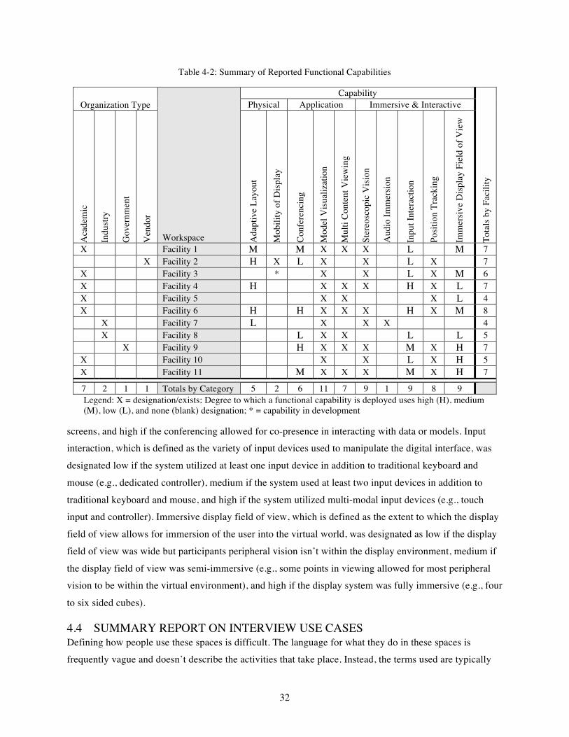
32
Table 4-2: Summary of Reported Functional Capabilities
Organization Type
Workspace
Capability
Tota
ls b
y Fa
cilit
y
Physical Application Immersive & Interactive
Aca
dem
ic
Indu
stry
Gov
ernm
ent
Ven
dor
Ada
ptiv
e La
yout
Mob
ility
of D
ispl
ay
Con
fere
ncin
g
Mod
el V
isua
lizat
ion
Mul
ti C
onte
nt V
iew
ing
Ster
eosc
opic
Vis
ion
Aud
io Im
mer
sion
Inpu
t Int
erac
tion
Posi
tion
Trac
king
Imm
ersi
ve D
ispl
ay F
ield
of V
iew
X Facility 1 M M X X X L M 7
X Facility 2 H X L X X L X 7 X Facility 3 * X X L X M 6 X Facility 4 H X X X H X L 7 X Facility 5 X X X L 4 X Facility 6 H H X X X H X M 8
X Facility 7 L X X X 4
X Facility 8 L X X L L 5
X Facility 9 H X X X M X H 7 X Facility 10 X X L X H 5 X Facility 11 M X X X M X H 7
7 2 1 1 Totals by Category 5 2 6 11 7 9 1 9 8 9 Legend: X = designation/exists; Degree to which a functional capability is deployed uses high (H), medium (M), low (L), and none (blank) designation; * = capability in development
screens, and high if the conferencing allowed for co-presence in interacting with data or models. Input interaction, which is defined as the variety of input devices used to manipulate the digital interface, was
designated low if the system utilized at least one input device in addition to traditional keyboard and
mouse (e.g., dedicated controller), medium if the system used at least two input devices in addition to
traditional keyboard and mouse, and high if the system utilized multi-modal input devices (e.g., touch input and controller). Immersive display field of view, which is defined as the extent to which the display
field of view allows for immersion of the user into the virtual world, was designated as low if the display
field of view was wide but participants peripheral vision isn’t within the display environment, medium if
the display field of view was semi-immersive (e.g., some points in viewing allowed for most peripheral vision to be within the virtual environment), and high if the display system was fully immersive (e.g., four
to six sided cubes).
4.4 SUMMARY REPORT ON INTERVIEW USE CASES Defining how people use these spaces is difficult. The language for what they do in these spaces is frequently vague and doesn’t describe the activities that take place. Instead, the terms used are typically

33
general meeting terms. The most common uses people reported were visualizing design information and
system information. These visualizing tasks were performed by a variety of participants including end users and maintenance personnel in addition to owner representatives, donors, stakeholders, design
professionals, engineers, and construction managers. For a list of reported interview use cases see Table
4-3.
The mode of definition of uses and activities interviewees reported included phase, task, building type,
system, user group, research topic, object of interest (e.g., model, drawing, etc.), and project name
(relevance to the user and their knowledge). These modes of definition were used as the starting point for the critical elements used in generating the ontology. In order to get a full picture of a specific use cases
most of these elements need to be known to represent the who, what, where, and when of a use case.
4.5 USERS OF FACILITIES In addition to facilities that are used for project teams, there are many different companies that have used interactive workspaces for their industry projects. Given the scope of this research and limitations of
identifying a comprehensive list of those who have used a facility, a limited number of organizations and
companies who have used facilities were found. Some instances of public information on a company for a
specific use case were found. These situations provided valuable information on context of project participants involved, more detailed use case information, phase application of use case, and occasionally
project benefits. This information is still anecdotal, yet provides some insight into general categories of
use case popularity. The list of users of facilities is difficult to identify given confidentiality, yet would
provide added details to future development of the ontology.
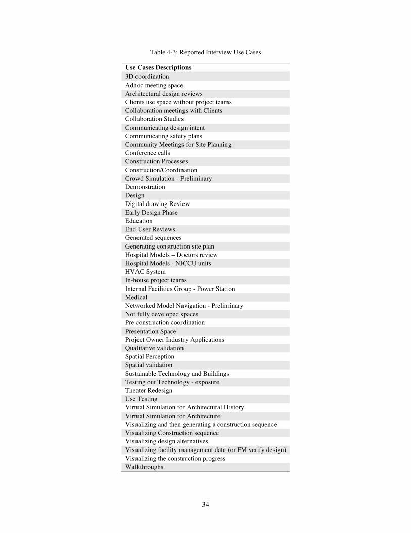
34
Table 4-3: Reported Interview Use Cases
Use Cases Descriptions 3D coordination Adhoc meeting space Architectural design reviews Clients use space without project teams Collaboration meetings with Clients Collaboration Studies Communicating design intent Communicating safety plans Community Meetings for Site Planning Conference calls Construction Processes Construction/Coordination Crowd Simulation - Preliminary Demonstration Design Digital drawing Review Early Design Phase Education End User Reviews Generated sequences Generating construction site plan Hospital Models – Doctors review Hospital Models - NICCU units HVAC System In-house project teams Internal Facilities Group - Power Station Medical Networked Model Navigation - Preliminary Not fully developed spaces Pre construction coordination Presentation Space Project Owner Industry Applications Qualitative validation Spatial Perception Spatial validation Sustainable Technology and Buildings Testing out Technology - exposure Theater Redesign Use Testing Virtual Simulation for Architectural History Virtual Simulation for Architecture Visualizing and then generating a construction sequence Visualizing Construction sequence Visualizing design alternatives Visualizing facility management data (or FM verify design) Visualizing the construction progress Walkthroughs
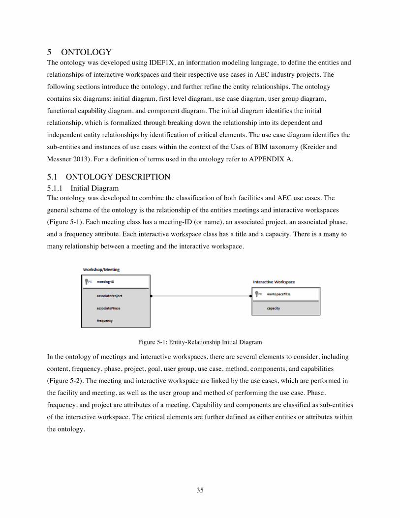
35
5 ONTOLOGY The ontology was developed using IDEF1X, an information modeling language, to define the entities and relationships of interactive workspaces and their respective use cases in AEC industry projects. The
following sections introduce the ontology, and further refine the entity relationships. The ontology
contains six diagrams: initial diagram, first level diagram, use case diagram, user group diagram,
functional capability diagram, and component diagram. The initial diagram identifies the initial relationship, which is formalized through breaking down the relationship into its dependent and
independent entity relationships by identification of critical elements. The use case diagram identifies the
sub-entities and instances of use cases within the context of the Uses of BIM taxonomy (Kreider and
Messner 2013). For a definition of terms used in the ontology refer to APPENDIX A.
5.1 ONTOLOGY DESCRIPTION 5.1.1 Initial Diagram The ontology was developed to combine the classification of both facilities and AEC use cases. The
general scheme of the ontology is the relationship of the entities meetings and interactive workspaces (Figure 5-1). Each meeting class has a meeting-ID (or name), an associated project, an associated phase,
and a frequency attribute. Each interactive workspace class has a title and a capacity. There is a many to
many relationship between a meeting and the interactive workspace.
Figure 5-1: Entity-Relationship Initial Diagram
In the ontology of meetings and interactive workspaces, there are several elements to consider, including
content, frequency, phase, project, goal, user group, use case, method, components, and capabilities (Figure 5-2). The meeting and interactive workspace are linked by the use cases, which are performed in
the facility and meeting, as well as the user group and method of performing the use case. Phase,
frequency, and project are attributes of a meeting. Capability and components are classified as sub-entities
of the interactive workspace. The critical elements are further defined as either entities or attributes within
the ontology.
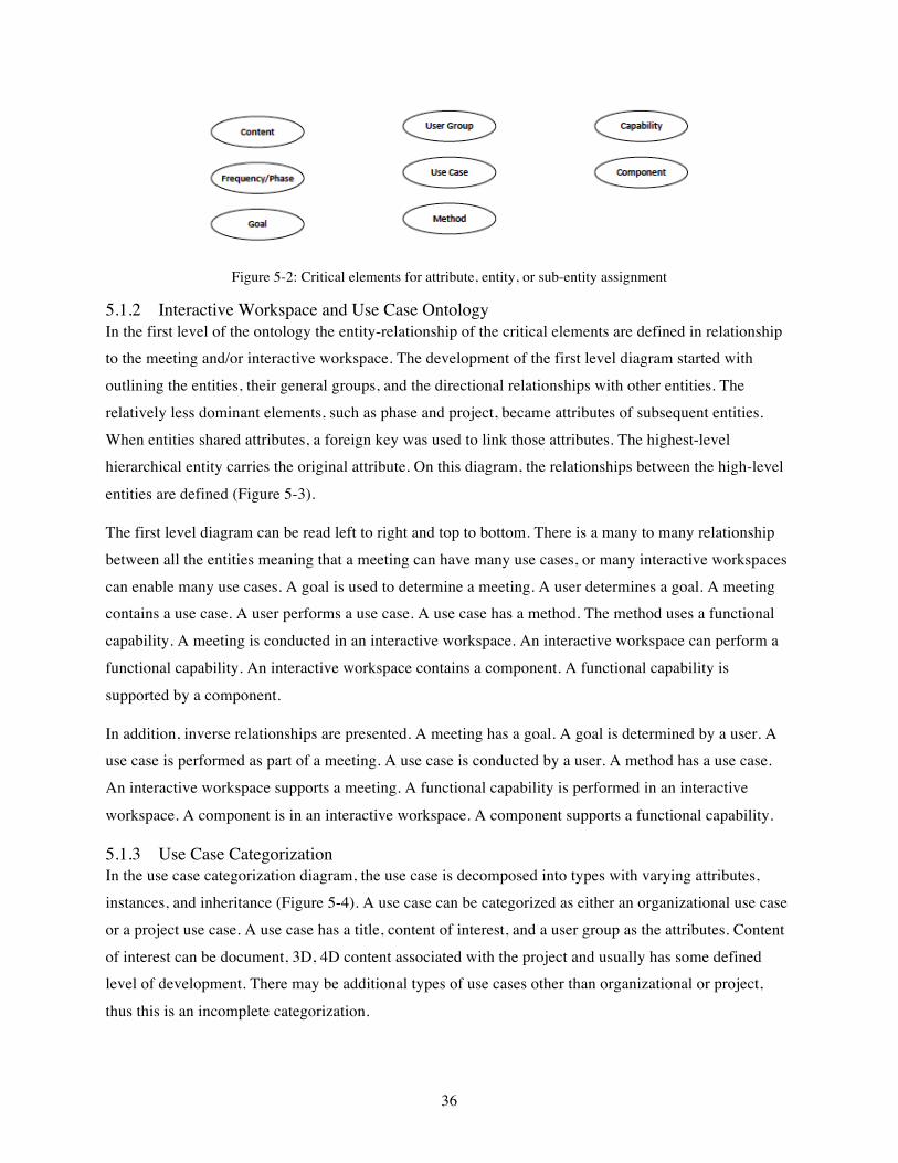
36
Figure 5-2: Critical elements for attribute, entity, or sub-entity assignment
5.1.2 Interactive Workspace and Use Case Ontology In the first level of the ontology the entity-relationship of the critical elements are defined in relationship to the meeting and/or interactive workspace. The development of the first level diagram started with
outlining the entities, their general groups, and the directional relationships with other entities. The
relatively less dominant elements, such as phase and project, became attributes of subsequent entities.
When entities shared attributes, a foreign key was used to link those attributes. The highest-level hierarchical entity carries the original attribute. On this diagram, the relationships between the high-level
entities are defined (Figure 5-3).
The first level diagram can be read left to right and top to bottom. There is a many to many relationship
between all the entities meaning that a meeting can have many use cases, or many interactive workspaces
can enable many use cases. A goal is used to determine a meeting. A user determines a goal. A meeting contains a use case. A user performs a use case. A use case has a method. The method uses a functional
capability. A meeting is conducted in an interactive workspace. An interactive workspace can perform a
functional capability. An interactive workspace contains a component. A functional capability is
supported by a component.
In addition, inverse relationships are presented. A meeting has a goal. A goal is determined by a user. A use case is performed as part of a meeting. A use case is conducted by a user. A method has a use case.
An interactive workspace supports a meeting. A functional capability is performed in an interactive
workspace. A component is in an interactive workspace. A component supports a functional capability.
5.1.3 Use Case Categorization In the use case categorization diagram, the use case is decomposed into types with varying attributes,
instances, and inheritance (Figure 5-4). A use case can be categorized as either an organizational use case
or a project use case. A use case has a title, content of interest, and a user group as the attributes. Content
of interest can be document, 3D, 4D content associated with the project and usually has some defined level of development. There may be additional types of use cases other than organizational or project,
thus this is an incomplete categorization.
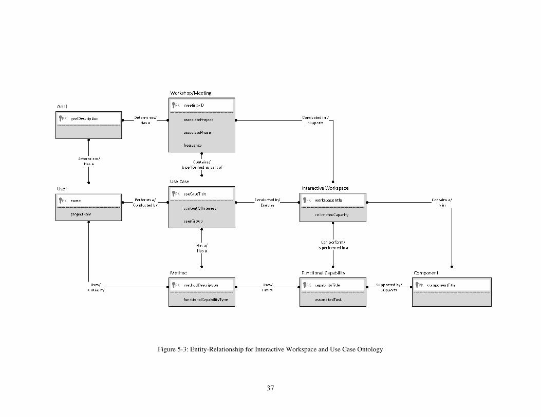
37
Figure 5-3: Entity-Relationship for Interactive Workspace and Use Case Ontology

38
Figure 5-4: Entity-Relationship for Use Case Categorization Diagram
39
An organizational use case has a use case title and an activity description. It has several different
instances: demonstration, outreach, training, and education. An organizational use case is different than a project use case by its application in that it is not project or phase specific. Demonstration can include
demonstrating technical ability, specific use cases, or project competence to a client. Outreach can include
outreach activities more specific than a demonstration such as community service outreach. Training can
include training on technical ability or on specific tasks. Education can include educational materials, serious games, and other education activities with employees. These activities are considered non-project
specific however may use cases developed on project specific use cases.
A project use case has a use case title, activity description, and associated phase. A project use case is
decomposed into two activities types: generating use case and visualize/analysis use case. The
categorization of project use case is an incomplete categorization as there are potentially other use case
activities.
A generating use case is specific to activities that are generating new content used in the project implementation, such as a collaborative planning session where design content or requirements are being
created. A visualize/analysis use case is specific to activities that are reviewing already generated content,
such as design review activities or collaborative analysis activities. A generating use case has attributes of
the generated content, associate phase, and generating activity. A visualize/analysis use case has the
visualized or analysis content, the associate phase, and the visualize/analysis activity.
The use case activities instances for both a generating use case (Figure 5-5a) and a visualize/analysis use
case (Figure 5-5b) are presented as the formalized summary of use cases found in the review of facilities
and in more detailed discussions with facility owners. Similar to results in the survey of spaces and the
use cases reported through interviews, there are more categories of use cases in the visualize/analysis use case activities than in generating use case activities. Generating use case activities include end user
requirement planning, program planning, design charrette, site layout planning, maintenance planning,
constructability planning, and sequence planning. Visualize/analysis use case activities include program
review, master plan review, design review, end user review, operations and maintenance (O&M) review, site safety review, site layout review, constructability review, sequence review, maintenance review, and
system review.
5.1.4 User Group Categorization The user group entity is an attribute of a use case. The user group has a quantity of people and can be composed of the intended user, organizer, technician, and developer (Figure 5-6). An intended user has a
name and a project role. An organizer has a name and a project role similar to a user. A technician has a
name and expertise pertaining to using a facility. A developer has a name and expertise pertaining to
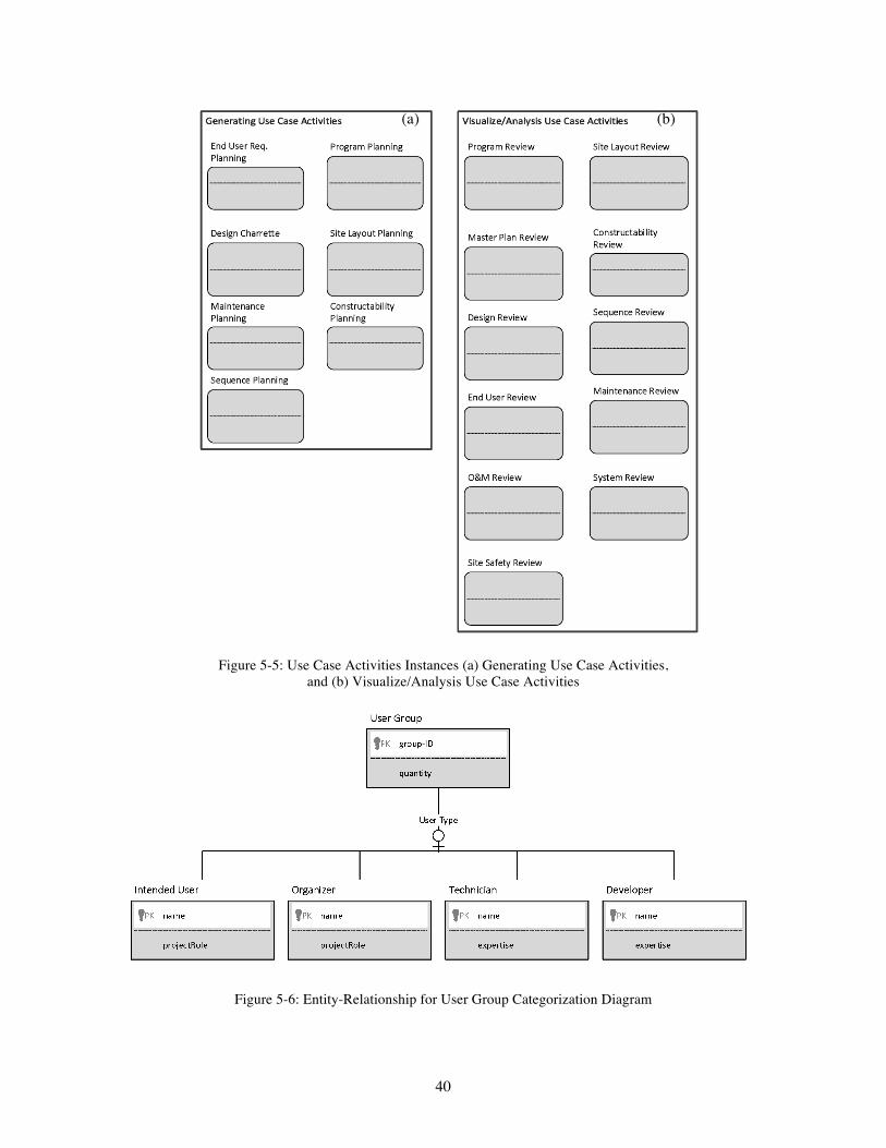
40
Figure 5-5: Use Case Activities Instances (a) Generating Use Case Activities,
and (b) Visualize/Analysis Use Case Activities
Figure 5-6: Entity-Relationship for User Group Categorization Diagram
(a) (b)
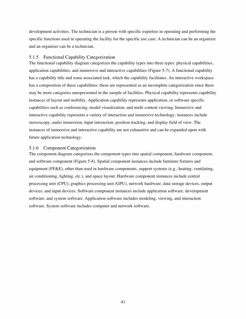
41
development activities. The technician is a person with specific expertise in operating and performing the
specific functions used in operating the facility for the specific use case. A technician can be an organizer
and an organizer can be a technician.
5.1.5 Functional Capability Categorization The functional capability diagram categorizes the capability types into three types: physical capabilities,
application capabilities, and immersive and interactive capabilities (Figure 5-7). A functional capability has a capability title and some associated task, which the capability facilitates. An interactive workspace
has a composition of these capabilities; these are represented as an incomplete categorization since there
may be more categories unrepresented in the sample of facilities. Physical capability represents capability
instances of layout and mobility. Application capability represents application, or software specific capabilities such as conferencing, model visualization, and multi content viewing. Immersive and
interactive capability represents a variety of interaction and immersive technology; instances include
stereoscopy, audio immersion, input interaction, position tracking, and display field of view. The
instances of immersive and interactive capability are not exhaustive and can be expanded upon with
future application technology.
5.1.6 Component Categorization The component diagram categorizes the component types into spatial component, hardware component, and software component (Figure 5-8). Spatial component instances include furniture fixtures and
equipment (FF&E), other than used in hardware components, support systems (e.g., heating, ventilating,
air conditioning, lighting, etc.), and space layout. Hardware component instances include central
processing unit (CPU), graphics processing unit (GPU), network hardware, data storage devices, output devices, and input devices. Software component instances include application software, development
software, and system software. Application software includes modeling, viewing, and interaction
software. System software includes computer and network software.
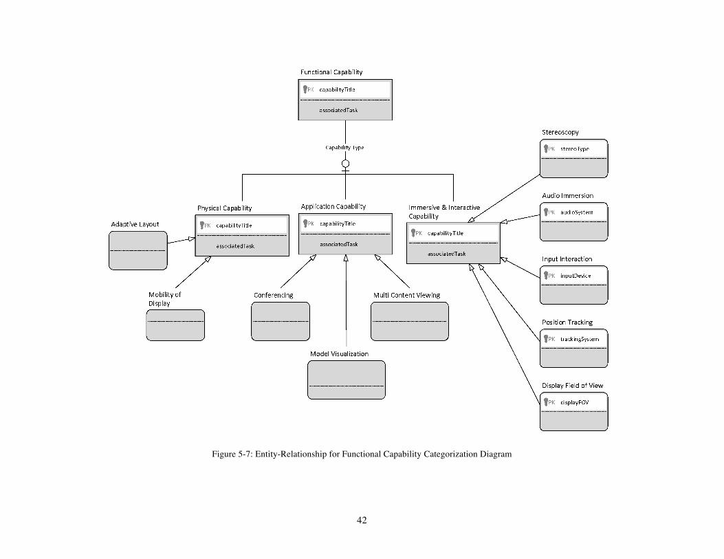
42
Figure 5-7: Entity-Relationship for Functional Capability Categorization Diagram

43
Figure 5-8: Entity-Relationship for Component Categorization Diagram
HVAC & Lighting
44
5.2 ONTOLOGY USAGE The ontology provides an initial structure of the entities, their attributes, their sub-entities, subsequent relationships, and instance. These can be used as a common language and classification system for cross-
disciplinary work in planning IW usage, implementation, and research into advanced visualization and
information technology techniques for group work in the AEC Industry. In addition, it can be useful for
industry sectors dependent on project specific work with multi-disciplinary teams.
The ontology was developed with flexibility in mind. As technology develops and changes instances of capabilities and components will change which can easily be added to the ontological structure. Further
refinement and definition of capabilities can occur. As methodology and process refinement occurs in the
activities conducted by AEC industry teams, the instances of activities can be refined and added.
5.2.1 Planning IW Use The ontology represents the critical entities needed to develop a specific use case in an interactive
workspace. Usage can start with a goal or a meeting definition and selection of specific use case
activities. A project team will need to define their methods and subsequent requirements of the functional capabilities of a specific interactive workspace. If a project team has already identified an interactive
workspace, they can use the ontology to identify some of the types of activities that may work best for the
project teams goals for various meetings.
5.2.2 Planning IW Implementation The ontology presents a variety of functional capabilities and components that can be selected based on
an organizations intended use of a facility. Selection should be based on goals and use cases desired,
however future functionality desires should also be considered. The ontology gives organizations a
structure for defining potential general collaboration activities and functional capabilities in addition to
components when designing a new interactive workspace.
5.2.3 Research Use The ontology can provide a common language and structure for documenting research case studies, facilities, and other research in the domains of AEC and collaborative tasks. The ontology presents a
starting point for visualization research into project team use case research for AEC industry applications.
In addition it can be further developed and refined to include future technology and expanded upon with
future research into specific tasks.

45
6 CONCLUSIONS This research explored interactive workspaces and their use in AEC industry use cases by documenting known facilities and organizing their reported usage in AEC application areas. Interviewing managers of
a selection of facilities gave insight into their attributes and specific information on categorizing use
cases. Analysis occurred of the literature, surveyed facilities, and interview content. Analysis of interview
content provided an overview of interactive workspaces usage in AEC industry application areas, defining the domain. Analysis of interview content also provided a list of critical elements, categories, and
relationships used in the development of the ontology. Two sets of validation occurred, first with initial
entities and relationships, and second with refined relationships and attributes. These validation activities
gave industry feedback into the reasonability of use case activities and relationships between entities.
6.1 FINDINGS In this research, 84 facilities were found, with 49 of them being used in AEC Industry application areas.
Of these facilities, 50% are in academia. A surprising number of these facilities were found in industry,
35% of all interactive workspaces. This indicates an investment of industry in advanced computing
environments to support complex tasks for project teams.
Interactive workspaces were found used predominantly for visualization and analysis purposes. The variety of communication purposes is heavily weighted towards visualization, which logically would
occur with AEC project teams. Analysis purposes were relatively balanced in the breakdown of types of
tasks (coordinate, validate, and forecast tasks). Generating purposes were found to be less frequent, yet
are shown throughout the literature to be some of the more compelling uses of interactive workspaces,
especially within the ubiquitous computing literature.
Of facilities being used in the AEC industry, thirteen interactive workspace representatives were
interviewed, representing eleven facilities. From these interviews a list of uses was developed and list of
critical elements were generated. Using the information gathered from literature and interviews, the list of
critical elements were integrated into an ontology linking use cases to interactive workspaces.
The definition of how interactive workspaces are used is complex, thus a simplified method was used to ensure all elements of a use (the who, what, where, and when) were linked to the why (goal) and how
(functional capabilities). From validation activities, the goal and the task need to be closely aligned and
project teams are recommended to view interactive workspaces as functional throughout iterative tasks in
the development of project.
6.2 CONTRIBUTIONS The main contributions of this research are the interactive workspace analysis and ontology of
workspaces and their use cases. Interactive workspaces in the AEC industry have been discussed in an
46
academic setting for over 15 years, yet surveying the breadth of spaces which are currently being used has
not been previously investigated. The interactive workspace analysis and ontology presents a major contribution to researchers investigating technology enabled collocated collaboration. Research in this
domain is primarily case study and/or proof-of-concept driven, and the ontology allows a method for
documenting case studies and documenting use cases and capabilities to support those activities. This
extends both the definition of interactive workspaces and allows methods for expanding research into
these complex systems.
6.3 LIMITAITONS The focus of this research was primarily on facility owners. Given that, users of facilities could
potentially give more detailed information on tasks and objectives of use cases within a facility. Owners
and managers were selected to provide overview information of current practices, general use cases, and general phase and project information. Future research into activities and tasks within meetings should
consider expert users as the focus.
The research presented is exploratory in nature and the list of facilities generated in preparation and
analysis of use cases and interactive workspace types is not comprehensive. Thus inferences cannot be
made generally to all interactive workspaces, only to those investigated.
As technology develops, new instances of features and components will be generated. The researcher developed the ontology to be categorized in a way that would facilitate future capabilities and use cases.
However, this means that most categories are not complete or cannot be deemed complete.
6.4 FUTURE RESEARCH AREAS There are several thrust of research recommended for future work including further ontology
development, identification of tasks, and research into specific use cases. In addition, an interactive
workspace guide development and future application development are discussed.
6.4.1 Future Ontology Development As with other ontologies, maintenance is a key, yet typically neglected, element. Research into further development, refinement, and validation of the ontology can help maintain the ontology as well as expand
it. Research into more specific relationships of the parts of the ontology is recommended, such as linking
specific functionality to components and linking specific use cases to instances of functionality. These
links can provide additional guidelines and criteria for selecting and using interactive workspaces. In addition, meeting ontologies or business models were not explored for potential integration with the
Interactive workspace and Use Case ontology, however this could be an interesting area for further
development in technology and collaborative interactions.
47
6.4.2 Task Based Research The ontology presented uses a framework of defining AEC activities within use cases of interactive
workspaces. Each category is relatively aligned with different types of tasks, which can be performed.
Research into specific tasks would be beneficial for investigating similarities between AEC activities and
other disciplines, which could aid research and development of visualization and interaction techniques beyond the discipline of the AEC industry and more generally across a variety of analysis, visualization,
and generative tasks used by collaborative teams.
6.4.3 Use Case Research It is recommended that further research occur into specific use cases, which are underrepresented in the
industry to date. The research found generating tasks have been adopted at a low rate, which are possibly
linked to difficulty in implementation given their focus on interaction applications that are still emerging
in the field. Research into specific use cases can give guidance to the limitations and criteria for selecting these use cases, while also providing development criteria to interaction designers, human-computer
interaction researchers, and/or virtual reality developers.
6.4.4 Guideline Application In tandem to this body of research, and as part of some of the initial investigation, the interactive workspace guide was developed and published in 2015 (Leicht et al. 2015, accessible:
interactiveworkspaces.weebly.com). The interactive workspace guide serves as a planning guide for
industry to plan the implementation and usage of interactive workspaces. As part of future development,
the interactive workspace guide should be further developed with integration of the ontology developed and presented here. In addition, the guide or other venue can adopt the ontology for documenting use
cases into a database. Such a depository would be helpful in developing deeper understanding of the
breadth of usage of these spaces, help in researching task specific scenarios, documenting best practices,
and formulating case based reasoning system, which could help implementation decision making.
6.4.5 Future Interactive Workspace Application Areas During the validation sessions, future ideas for how one could use these types of facilities were discussed.
Some of these areas included connecting the facility to the job-site activities through leveraging drone technology, augmented and mixed reality, and conferencing technology. Such application areas can gain
insight from distributed medical practices research. Another area discussed was the use of networked
avatars within a virtual world, either for distributed team members or collocated team members. These
application areas start to blur the line between distributed and collocated teams and present interesting areas of research for use and usability of systems which allow access to the type and quantity of
information needed to support complex tasks for these multidisciplinary project teams.
48
BIBLIOGRAPHY Bjørn, P., Esbensen, M., Jensen, R. E., and Matthiesen, S. (2014). “Does distance still matter? Revisiting
the CSCW fundamentals on distributed collaboration.” ACM Trans. Comput.-Hum. Interact. 21(5), 27:1–27:26.
Bruce, T. A. (1992). Designing Quality Databases with IDEF1X Information Models. Dorset House Pub, New York, NY.
Dennis, A. R., Fuller, R. M., and Valacich, J. S. (2008). “Media, tasks, and communication processes: A theory of media synchronicity.” MIS Quarterly, 32(3), 575–600.
Fernandes, K. J., Raja, V., White, A., and Tsinopoulos, C.-D. (2006). “Adoption of virtual reality within construction processes: a factor analysis approach.” Technovation, 26(1), 111–120.
Fernandez, M., Gomez-Perez, A., and Juristo, N. (1997). “Methontology: From ontological art towards ontological engineering.” Proceedings of the AAAI97 Spring Symposium Series on Ontological Engineering, 33–40.
Fernando, T. (2008). “Future collaborative workspaces for the construction industry.” Virtual Futures for Design, Construction & Procurement, edited by P. Brandon and T. Kocatu ̈rk, Blackwell Publishing Ltd., 278–289.
Garcia, A. C. B., Kunz, J., Ekstrom, M., and Kiviniemi, A. (2004). “Building a project ontology with extreme collaboration and virtual design and construction.” Advanced Engineering Informatics, Ontology and Its Applications to Knowledge-Intensive Engineering, 18(2), 71–83.
Gómez-Pérez, A., Fernández, M., and Vicente, A. de. (1996). “Towards a method to conceptualize domain ontologies.” Proc., 12th European Conference on Artificial Intelligence (ECAI’96), Wiley, 08/13/1996, Budapest, Hungary.
Gruber, T. R. (1995). “Toward principles for the design of ontologies used for knowledge sharing.” International Journal of Human Computer Studies, 43(5), 907–928.
Isenberg, P., Elmqvist, N., Scholtz, J., Cernea, D., Ma, K.-L., and Hagen, H. (2011). “Collaborative visualization: definition, challenges, and research agenda.” Information Visualization Journal, SAGE, 2011, Special Issue on Information Visualization: State of the Field and New Research Directions, 10(4), 310–326.
Johanson, B., and Fox, A. (2004). “Extending tuplespaces for coordination in interactive workspaces.” Journal of Systems and Software, 69(3), 243–266.
Jones, D., Bench-Capon, T., and Visser, P. (1998). “Methodologies for ontology development.” Proc. IT&KNOWS Conference of the 15th IFIP World Computer Congress. OCG. August, 1998, Budapest, Hungary. 62-75.
Khanzode, A. (2012). “Making the integrated big room better.” DPR Construction, <http://www.dpr.com/assets/docs/Big-Room-Whitepaper.pdf> (Mar. 31, 2014).
Kim, M. J., Wang, X., Love, P. E., Li, H., and Kang, S. C. (2013). “Virtual reality for the built environment: a critical review of recent advances.” Journal of Information Technology in Construction, 18(279-305).
Kreider, R., and Messner, J. I. (2013). The Uses of BIM. The Pennsylvania State University, University Park, PA, Available at: bim.psu.edu.
Laha, B., and Bowman, D. A. (2012). “Identifying the benefits of immersion in virtual reality for volume data visualization.” Immersive visualization revisited workshop of the IEEE VR conference, 1–2.
Laha, B., Bowman, D. A., Laidlaw, D. H., and Socha, J. J. (2015). “A classification of user tasks in visual analysis of volume data.” IEEE Scientific Visualization Conference 2015, IEEE, October 25-30, Chicago, IL, USA.
Leicht, R. M. (2009). “A framework for planning effective collaboration using interactive workspaces.” Ph.D., The Pennsylvania State University, University Park, PA.
Leicht, R., Messner, J., and Poerschke, U. (2012a). “INVOLVE: Planning interactive workspaces to improve communication using virtual prototypes.” Computing in Civil Engineering, 191–201.
49
Leicht, R. M., and Messner, J. I. (2009). “Improving site utilization planning through the use of interactive workspaces.” 2009 Construction Research Congress, Seattle, Washington, 45–45.
Leicht, R. M., Messner, J. I., Chen, K., Lather, J., Luttmann, E., Liu, Y., and Macht, G. A. (2015). Interactive workspaces: A guide to integrating interactive workspaces into facility projects. Consortium for Building Energy Innovation, Philadelphia, PA.
Leicht, R. M., Messner, J. I., and Poerschke, U. (2012b). “INVOLVE: Developing interactive workspaces that impact communication and task performance when using virtual prototypes.” Journal of Computing in Civil Engineering, 28(2), 191–201.
Leon, M., and Laing, R. (2013). “Towards a computer mediated methodology for collaborative design during the early architectural design stages.” 2013 IEEE 17th International Conference on Computer Supported Cooperative Work in Design (CSCWD), 489–495.
Liston, K., Fischer, M., and Kunz, J. (2000). “Requirements and benefits of interactive information workspaces in construction.” 8th International Conference on Computing in Civil and Building Engineering, August, 2000, 14–17.
MacLeamy, P. (2010). “The future of the building industry (3/5): the effort curve.” YouTube, <http://www.youtube.com/watch?v=9bUlBYc_Gl4&feature=youtube_gdata_player> (Mar. 31, 2014).
Mark, G. (2002). “Extreme collaboration.” Communications of the ACM, 45(6), 89 – 93. Merschbrock, C., and Munkvold, B. E. (2012). “A research review on building information modeling in
construction: An area ripe for IS research.” Communications of the Association for Information Systems, 31, 207–228.
Messner, J. I., and Leicht, R. M. (2012). “Experiencing digital design: Developing interactive workspaces for visualizing, editing and interacting with digital design artifacts.” Computational Design Methods and Technologies: Applications in CAD, CAM and CAE, IGI Global, 238–256.
Milgram, P., and Kishino, F. (1994). “A taxonomy of mixed reality visual displays.” Transactions on Information Systems, E77-D(12), 1321 – 1329.
National Institute of Building Sciences. (2014). “About the National BIM Standard - United States.” Initiative of the National Institute of Building Sciences buildingSMART alliance (Apr. 28, 2014).
Neff, G., Fiore-Silfvast, B., and Dossick, C. S. (2010). “A case study of the failure of digital communication to cross knowledge boundaries in virtual construction.” Information, Communication & Society, 13(4), 556–573.
Noy, N. F., and McGuinness, D. L. (2001). Ontology Development 101: A Guide to Creating Your First Ontology. Technical Report, Stanford Knowledge Systems Laboratory Technical Report KSL-01-05 and Stanford Medical Informatics Technical Report SMI-2001-0880.
Olson, G. M., and Olson, J. S. (2000). “Distance matters.” Human-Computer Interaction, 15(2/3), 139–178.
Papadopoulos, C., Laha, B., and Kaufman, A. E. (2014). “Interacting with Mixed Reality Systems.” Death of the Desktop: Envisioning Visualization without Desktop Computing Workshop, Paris, France.
Rentzos, L., Smparounis, K., Mavrikios, D., and Chryssolouris, G. (2012). “An Ontology For Classifying Advanced Visualization Infrastructures.” 14th International Conference on Modern Information Technology in the Innovation Processes of Industrial Enterprises (MITIP), Budapest, Hungary.
Russell, D. M., Streitz, N. A., and Winograd, T. (2005). “Building disappearing computers.” Commun. ACM, 48(3), 42–48.
Sanvido, V. E., Khayyal, S. A., Guvenis, M., Norton, K., Hetrick, M., Muallem, M., Chung, E. K., and Medeiros, D. J. (1990). An integrated building process model. Computer Integrated Construction Research Program, Department of Architectural Engineering, the Pennsylvania State University, University Park, PA.
Smith, A., Alexander, D., Fragaki, A., Jones, P., and Lannon, S. (2008). “VIRVIL, A 3D virtual village to assess the impact of low and zero carbon technologies in the built environment.” Visualisation, 2008 International Conference, 23–28.

50
Ware, C. (2012). Information visualization perception for design. Morgan Kaufmann, Boston. Whyte, J. (2002). Virtual reality and the built environment. Architectural Press, Oxford, U.K. Whyte, J. (2003). “Industrial applications of virtual reality in architecture and construction.” ITcon Vol. 8,
(Special Issue Virtual Reality Technology in Architecture and Construction), 43–50. Woksepp, S., and Olofsson, T. (2006). “Using virtual reality in a large-scale industry project.” ITcon, 11,
627–640. Woksepp, S., and Olofsson, T. (2008). “Credibility and applicability of virtual reality models in design
and construction.” PLM Challenges, 22(4), 520–528.
51
APPENDIX A: DEFINITIONS Activity: A set of tasks used to complete a more general use case.
Adaptive Layout: The capability to arrange a facility’s furnishings (e.g., tables and chairs) to facilitate different meeting environments.
Application Capability: A function of an interactive workspace that is based on an application or a set of software.
Application Software: The software used for specific applications, such as model viewers.
Attribute: a property of a functional capability, e.g., location tracking is a functional capability, and one instance of location tracking may have the attribute of IR tracking or use a different property enabling the same function.
Audio Immersion: A function of an interactive workspace to support audio immersion.
Collocated Capacity: The capacity of collocated participants in an Interactive Workspace.
Component: A spatial, hardware, or software element found in the system or in the workspace.
Conferencing: The function of connecting outside meeting participants with support of audio, video, or application tools.
Constructability Planning: An activity to plan and design solutions to enable the efficient construction of a facility.
Constructability Review: An activity focused on the review of project constructability for the proposed project or components of the proposed project.
Content of Interest: The content (e.g., model, plans, section, data, analysis) which is needed to support the goals and purpose of a specific use case
Demonstration Use Case: The use of an interactive workspace for demonstrating some expertise or technological capability for to purpose of exposure to new audiences (e.g., clients).
Design Charrette: An intensive design and planning activity where ideas are formulated on design vision, scope, and/or initial layout and development, usually marked by participation of both project team members and various stakeholders.
Design Review: An activity to review the design, typically performed at various stages of design progression such as conceptual, schematic, design development, and construction documents.
Development Software: The specific software used to develop content for use in the interactive workspace, such as modeling software.
Education Use Case: The use of an interactive workspace for learning activities.
End User Requirement Planning: A planning activity to identify and define project requirements with participation from the end users and other project team members for a proposed project.
End User Review: An activity focused on obtaining feedback about the facility design, requirements, and/or operations from end users of a proposed project.
FF&E: Furnishing, fixtures, and equipment used in the space to support the hardware components (e.g., tables, chairs, etc.)
52
Functional Capability: A function that is capable to be performed in an interactive workspace. A functional capability may contain sets of features that are supported by the environment and components of the system which when combined support the specific function.
Generating Use Case: A use of an interactive workspace for the fulfillment of goals specific to generating content used in the planning, designing, delivery, and/or operations of a project or set of projects.
Goal: A purpose for an instance of utilizing an interactive workspace, such as for a specific review of documents.
HVAC & Lighting: The infrastructure systems used to support the workspace, e.g., cooling systems, specific lighting systems, etc.
Immersive and Interactive Capability: A function of an interactive workspace that is based on a set of hardware and software capabilities allowing for specific immersive and interactive functions.
Immersive Display Field of View: The function of an interactive workspace to support user immersion through the extent of the virtually observable world that is seen at any given moment.
Input Interaction: The function of interaction as specified by a specific input device (e.g., gesture, touch, etc.)
Interactive Workspace (IW): An interactive workspace is a physically located technology-‐‑ and media-‐‑enabled project space facilitating human centered interaction and meaningful collaborations of project team members utilizing heterogeneous devices and software featuring large format displays, for content sharing and media viewing, and multi-‐‑modal interaction systems.
Level of Development: The level by which the content, and specific parts and pieces of the content needs to be developed in order to effectively meet the goals and purpose of a specific use case (or workshop/meeting)
Maintenance Planning: An activity to develop the maintenance plan for a proposed project.
Maintenance Review: An activity focused on reviewing the project to obtain feedback about the maintenance of a proposed project.
Master Plan Review: An activity focused on the review of a master plan (e.g., urban plan, campus plan).
Method: The procedure used for accomplishing a given use case, specific to the functional capabilities deployed.
Mobility of Display: The function of an interactive workspace to be transported and set up in various locations.
Model Visualization: The function of an interactive workspace to view model representations of project content.
Multi Content Viewing: The function of an interactive workspace to view multiple content simultaneously via multi-screens, window in window display, or video switching.
Operations and Management (O&M) Review: A review activity specifically for obtaining feedback about the operations and management of the proposed project, such as reviewing overall efficiency or ease of operations.
Organizational Use Case: A use of an interactive workspace for the fulfillment of goals specific to an organization or company.

53
Outreach Use Case: The use of an interactive workspace for outreaching public or targeted groups (e.g., youth, underrepresented minorities)
Physical Capability: A function of an interactive workspace that is based on the physical or spatial qualities of the facility.
Position Tracking: A function of an interactive workspace to track the position of a user or object in three dimensional space and process that information for interaction with digital content (e.g., position in a virtual world, perspective adjustments for stereoscopic images)
Program Planning: A planning activity focused on the development of project program.
Program Review: A review activity where project program is reviewed.
Project Role: The role a user has in the context of the project.
Project Use Case: A specific use of an interactive workspace for the fulfillment of goals specific to aid the planning, design, delivery, and/or operations of a project or set of projects.
Sequence Planning: A design and planning activity to develop the construction sequences.
Sequence Review: An activity to review the construction sequence of a project, which may include overall project phasing or focus on a specific portion of the construction sequence.
Site Layout Planning: A planning and design activity where the site layout during construction for the temporary equipment, structures, laydown areas, and work plans are developed.
Site Layout Review: A review activity for reviewing site layout of final and/or temporary structures associated with the proposed project.
Site Safety Review: An activity to review the planned construction phases for safety considerations, such as access routes and crane locations, as well as project specific safety concerns.
Space Layout: The spatial configuration of the workspace.
Stereoscopy: A function of a facility to process two images of the same object taken at slightly different angles, creating an impression of depth and solidity, by either passive or active means.
System Review: An activity to review the building system design(s), such as a mechanical system, electrical system, enclosure system, or structural system review.
System Software: The software used by the computer hardware, such as drivers etc.
Training Use Case: The use of an interactive workspace for applied educational activities.
Use Case: A use of an interactive workspace for performing architectural, engineering, or construction tasks.
User Group: The participants needed to perform a use case.
Visualize/Analyze Use Case: A use of an interactive workspace for the fulfillment of goals specific to visualizing and/or analyzing content used in the planning, designing, delivery, and/or operations of a project or set of projects.
Workshop/Meeting: a set of activities performed with purpose by a coordinated set of individuals. For the scope of this ontology, the set of individuals is assumed to be multi-disciplinary and inter-organizational.

54
APPENDIX B: INTERVIEW PROTOCOL IW OWNER/MANAGER INTERVIEW PROTOCOL INTERVIEW STEPS 1. Review any public documentation about the interactive workspace. Fill out Sections A and B
(Interview Background and Interactive Workspace Attributes).
2. Contact Facility Owner/Manager to participate in the interview, include recruitment script, a
personalized email, summary of research, and consent form.
3. Schedule interview.
4. Additional Information. Ask for images or diagram of layout of Interactive Workspace (if not publicly
available and still unknown).
5. Review Sections A &B questions for clarity and completeness. Customize list to validate known
information.
6. Conduct Interview, record if possible.
7. Review interview. Create mind-map of interactive workspace.
8. Follow up.
55
IW OWNER/MANAGER INTERVIEW RECRUITMENT SCRIPT E-mail or verbal Recruitment script to participate in an interview: To Whom It May Concern, Based on your experience with _____________________ interactive workspace, we would like to interview you to gain information about developing and deploying interactive workspaces within the Architectural, Engineering, and Construction industry. The study we are conducting is evaluating the effectiveness of immersive and interactive workspaces to support the design review process. As part of our research, we would like to invite you to participate in an interview and share your experiences with industry projects in your space. Your expertise will be used to benchmark industry adoption of these media-enabled spaces. If you are interested in participating, please respond via e-mail and let us know when is a good time to schedule an interview. Your input in this study would be very valuable given your expertise in ___________________________. With this letter, you will receive a copy of the implied consent document and a project summary with more details on the study. If you do not wish to participate in the study, you can disregard this letter. Please let us know if there are any questions or concerns. Sincerely, John I. Messner Principal Investigator Robert Leicht Yifan Liu, Jennifer Lather, Co-Investigators _____________________________________________________ Dept. Architectural Engineering Penn State University University Park, PA 16802 [email protected] [email protected] [email protected] [email protected]
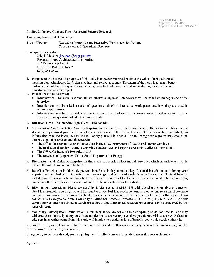
56
57
IW OWNER/MANAGER INTERVIEW PROTOCOL FORM Institution(s):
Interviewee (Title and Name):
Interviewer:
Format: In-Person / Video / Phone Date: Location:
Documents Obtained:
Photos (if not publicly available)
Diagrams of Space (if not publicly available)
Interview Sections Used:
A: Interview Background
B: Interactive Workspace & Attributes
C: Workspace Setup
D: Interactive Workspace Facility
E: Uses of the Interactive Workspace
F: Project Case Studies
G: Wrap up Questions
Other Topics Discussed:
Interview Comments or Leads:
Follow up: Email / Phone Date:
Post Interview Comments or Leads:
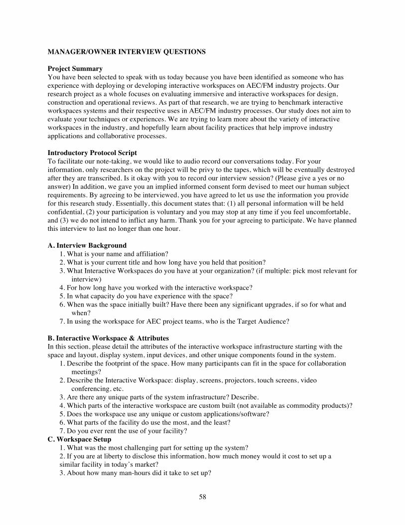
58
MANAGER/OWNER INTERVIEW QUESTIONS Project Summary You have been selected to speak with us today because you have been identified as someone who has experience with deploying or developing interactive workspaces on AEC/FM industry projects. Our research project as a whole focuses on evaluating immersive and interactive workspaces for design, construction and operational reviews. As part of that research, we are trying to benchmark interactive workspaces systems and their respective uses in AEC/FM industry processes. Our study does not aim to evaluate your techniques or experiences. We are trying to learn more about the variety of interactive workspaces in the industry, and hopefully learn about facility practices that help improve industry applications and collaborative processes. Introductory Protocol Script To facilitate our note-taking, we would like to audio record our conversations today. For your information, only researchers on the project will be privy to the tapes, which will be eventually destroyed after they are transcribed. Is it okay with you to record our interview session? (Please give a yes or no answer) In addition, we gave you an implied informed consent form devised to meet our human subject requirements. By agreeing to be interviewed, you have agreed to let us use the information you provide for this research study. Essentially, this document states that: (1) all personal information will be held confidential, (2) your participation is voluntary and you may stop at any time if you feel uncomfortable, and (3) we do not intend to inflict any harm. Thank you for your agreeing to participate. We have planned this interview to last no longer than one hour. A. Interview Background
1. What is your name and affiliation? 2. What is your current title and how long have you held that position? 3. What Interactive Workspaces do you have at your organization? (if multiple: pick most relevant for
interview) 4. For how long have you worked with the interactive workspace? 5. In what capacity do you have experience with the space? 6. When was the space initially built? Have there been any significant upgrades, if so for what and
when? 7. In using the workspace for AEC project teams, who is the Target Audience?
B. Interactive Workspace & Attributes In this section, please detail the attributes of the interactive workspace infrastructure starting with the space and layout, display system, input devices, and other unique components found in the system.
1. Describe the footprint of the space. How many participants can fit in the space for collaboration meetings?
2. Describe the Interactive Workspace: display, screens, projectors, touch screens, video conferencing, etc.
3. Are there any unique parts of the system infrastructure? Describe. 4. Which parts of the interactive workspace are custom built (not available as commodity products)? 5. Does the workspace use any unique or custom applications/software? 6. What parts of the facility do use the most, and the least? 7. Do you ever rent the use of your facility?
C. Workspace Setup 1. What was the most challenging part for setting up the system? 2. If you are at liberty to disclose this information, how much money would it cost to set up a similar facility in today’s market? 3. About how many man-hours did it take to set up?
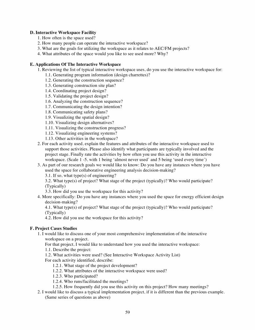
59
D. Interactive Workspace Facility 1. How often is the space used? 2. How many people can operate the interactive workspace? 3. What are the goals for utilizing the workspace as it relates to AEC/FM projects? 4. What attributes of the space would you like to see used more? Why?
E. Applications Of The Interactive Workspace 1. Reviewing the list of typical interactive workspace uses, do you use the interactive workspace for:
1.1. Generating program information (design charrettes)? 1.2. Generating the construction sequence? 1.3. Generating construction site plan? 1.4. Coordinating project design? 1.5. Validating the project design? 1.6. Analyzing the construction sequence? 1.7. Communicating the design intention? 1.8. Communicating safety plans? 1.9. Visualizing the spatial design? 1.10. Visualizing design alternatives? 1.11. Visualizing the construction progress? 1.12. Visualizing engineering systems? 1.13. Other activities in the workspace?
2. For each activity used, explain the features and attributes of the interactive workspace used to support those activities. Please also identify what participants are typically involved and the project stage. Finally rate the activities by how often you use this activity in the interactive workspace. (Scale 1 -5, with 1 being ‘almost never used’ and 5 being ‘used every time’)
3. As part of our research goals we would like to know: Do you have any instances where you have used the space for collaborative engineering analysis decision-making? 3.1. If so, what type(s) of engineering? 3.2. What type(s) of project? What stage of the project (typically)? Who would participate? (Typically) 3.3. How did you use the workspace for this activity?
4. More specifically: Do you have any instances where you used the space for energy efficient design decision-making? 4.1. What type(s) of project? What stage of the project (typically)? Who would participate? (Typically) 4.2. How did you use the workspace for this activity?
F. Project Cases Studies 1. I would like to discuss one of your most comprehensive implementation of the interactive
workspace on a project. For that project, I would like to understand how you used the interactive workspace: 1.1. Describe the project: 1.2. What activities were used? (See Interactive Workspace Activity List) For each activity identified, describe:
1.2.1. What stage of the project development? 1.2.2. What attributes of the interactive workspace were used? 1.2.3. Who participated? 1.2.4. Who runs/facilitated the meetings? 1.2.5. How frequently did you use this activity on this project? How many meetings?
2. I would like to discuss a typical implementation project, if it is different than the previous example. (Same series of questions as above)
60
3. What was the most successful project you had in the workspace? What activities made it successful?
G. Wrap Up Questions
1. What activities would you would be valuable to perform, but you find challenging to implement? 2. What challenges do you have related to finding users for the space? 3. If the interactive workspace was redesigned, what would you do differently? 4. Do you benchmark your workspace performance against any other workspace? 5. Do you mind if we contact your collaborators? (Name & emails will only be used internally for the
scope of this research.)

61
APPENDIX C: EXAMPLE MIND MAP
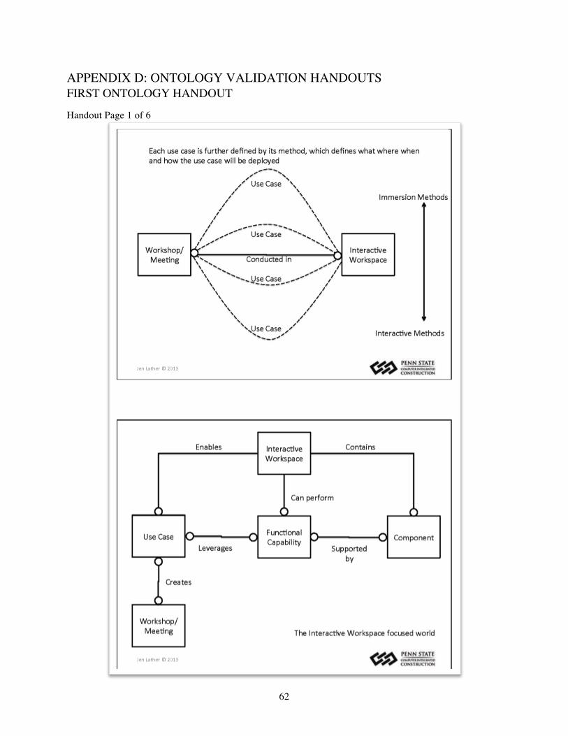
62
APPENDIX D: ONTOLOGY VALIDATION HANDOUTS FIRST ONTOLOGY HANDOUT
Handout Page 1 of 6

63
Handout Page 2 of 6
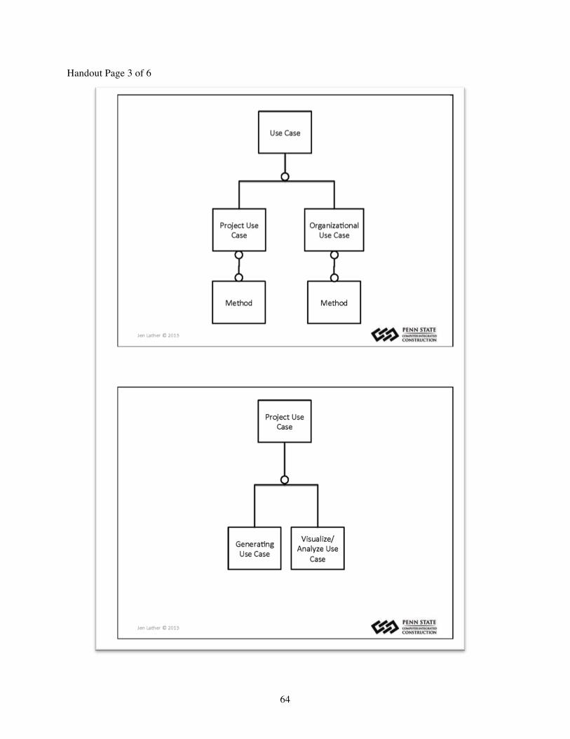
64
Handout Page 3 of 6
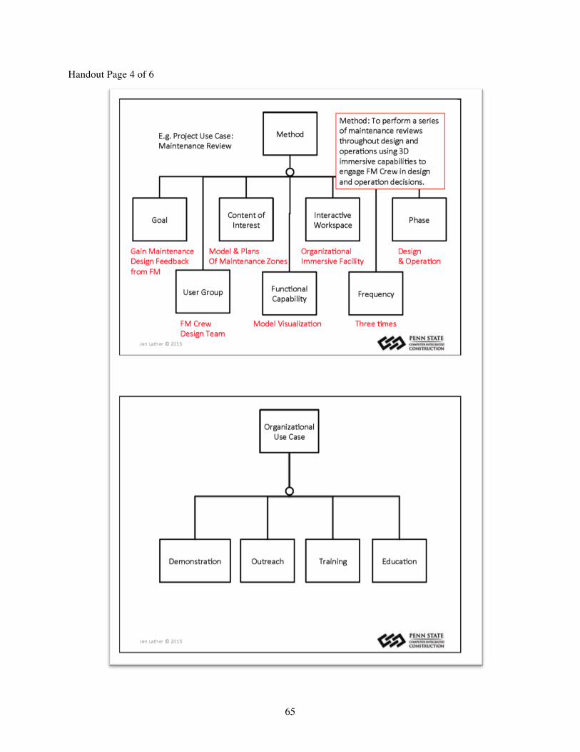
65
Handout Page 4 of 6

66
Handout Page 5 of 6

67
Handout Page 6 of 6
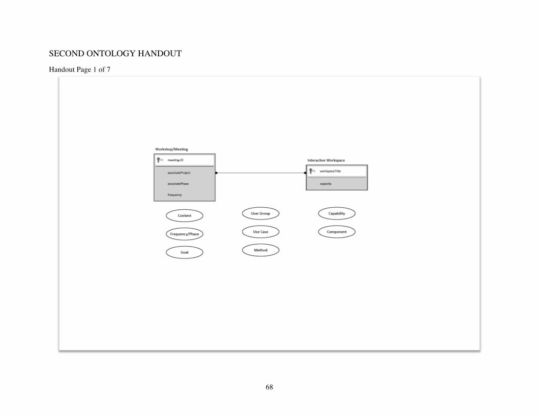
68
SECOND ONTOLOGY HANDOUT
Handout Page 1 of 7
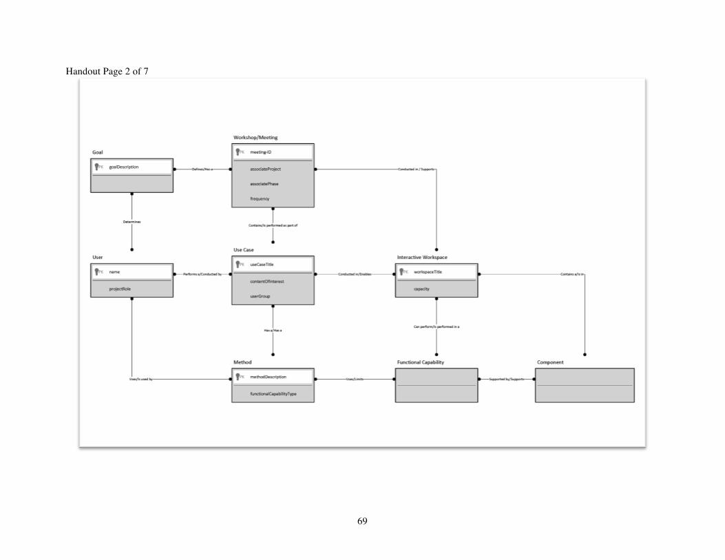
69
Handout Page 2 of 7

70
Handout Page 3 of 7
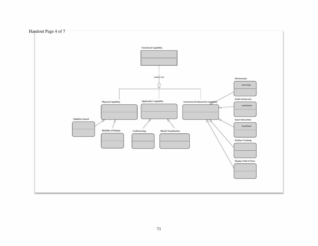
71
Handout Page 4 of 7

72
Handout Page 5 of 7
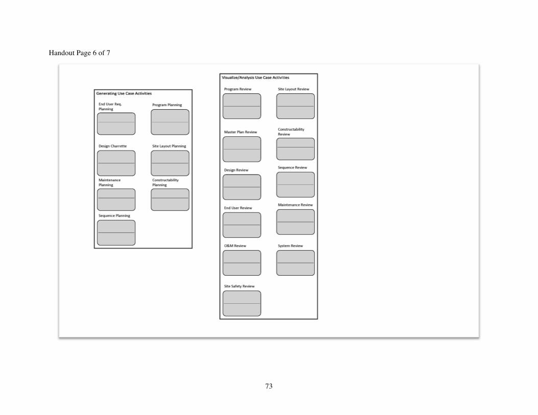
73
Handout Page 6 of 7
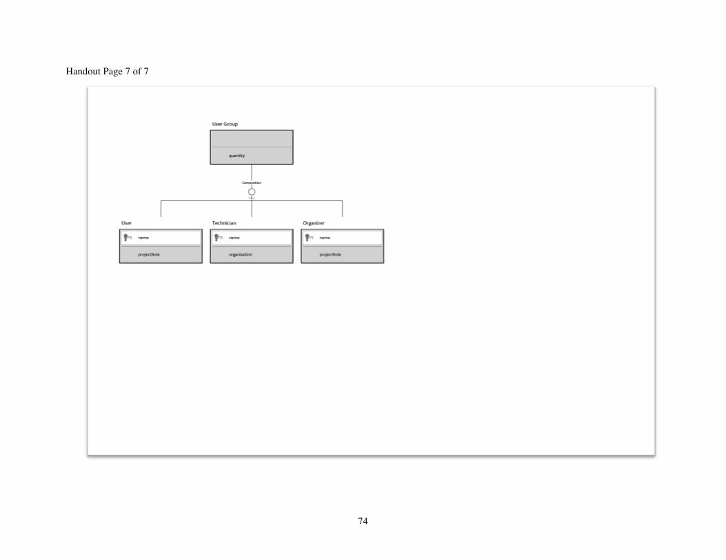
74
Handout Page 7 of 7