an investigation of late palaeolithic stone tool assemblages from
TRANSCRIPT

AN INVESTIGATION OF LATE PALAEOLITHIC STONE TOOL
ASSEMBLAGES FROM THE NEJD PLATEAU, SOUTHERN OMAN
byYamandú Hieronymus Hilbert
A thesis submitted to theUniversity of Birmingham
for the degree ofDOCTOR OF PHILOSOPHY
Institute of Archaeology and AntiquityUniversity of Birmingham September 2012

University of Birmingham Research Archive
e-theses repository This unpublished thesis/dissertation is copyright of the author and/or third parties. The intellectual property rights of the author or third parties in respect of this work are as defined by The Copyright Designs and Patents Act 1988 or as modified by any successor legislation. Any use made of information contained in this thesis/dissertation must be in accordance with that legislation and must be properly acknowledged. Further distribution or reproduction in any format is prohibited without the permission of the copyright holder.


to Eva Hilbert


Abstract
Technological and typological analysis of lithic assemblages from southern
Oman have been undertaken for this study. These assemblages are characterized by the
production of elongated end products (i.e., blades/leptoliths) using varied core reduction
modalities exemplified here. These modalities have been identified based on technological
analysis of production waste and core reconstructions using artefact refittings. Such blade
technologies are accompanied by formal tool such as tanged projectile called Fasad point,
burins, endscrapers and pseude-backed knifes. This technological and typological package
has been identified on both systematic surface collections and stratified sites, making it
possible to place these assemblages chronologically between 10.000 and 7.000 before
present (BP). The chronological and techno-typological characterization of these blade
assemblages warrants its status as a lithic industry of the Late Palaeolithic technocomplex.
At present, blade assemblages from stratified sites in Yemen (Shi’bat Dihya) and Oman (al
Hatab) which dated to 55.000 and 11.000 BP, represent the possible source of the techno/
typological package found across Southern Oman at the beginning of the Holocene. No
technological or typological resemblance with any other industry from outside of Arabia
has been noted, enforcing the local , Arabian, origin of the Early Holocene Populations of
the South Arabian Highlands.
An Investigation of Late Palaeolithic Stone Tool Assemblages from the Nejd Plateau, Southern Oman
Yamandú Hieronymus Hilbert


Acknowledgments
The process of writing this dissertation would not have been possible without the undying support of a few people and a legion of friends; first and foremost I am in debt to my advisor Dr. Jeffrey Rose who has been like a brother to me since I started the Ph.D program in 2009. From letting me live in his house in England for over 6 month (without paying any rent), helping me financially and feeding me across these past three years and so many other things, thanks Jeff ; I will never be able to pay you back. I also owe a great deal to Prof. Anthony Marks, for supporting me from the start when all seemed lost and I was almost ready to look for a real job (a cook or something like that), thanks Tony. For all the help with the bureaucratic jungle nightmare that are English academic institutions I am in debt to Dr. Paul Garwood, my second supervisor. For nearly maddening discussions about technological processes and intentionality outside the Levallois technological mantle I am grateful to Dr. Vitaly Usik. Thanks also goes to the remaining DAP team members, Amir Beshkani, Chris Galletti, Ash Parton, Dr. Mike Morley. I am also grateful for the Australian dating specialists Prof. Bert Roberts and Lauren Linnenlucke; thanks and keep the dates coming. For very insightful discussions and memorable hang over I am grateful to Dr. Rémy Crassard, Ash Parton, Viola Schmidt, Christoph Wissing, Björn Bitterlich, Dominik Koscielny, Dr. Hannes Napirala, Bernd Trautmann, Krischan Hoyer and Dr. Paul Preston. Which comes to show that it has not all been rocks and sand for the past three years, to all those with whom I have spent my spare time and kept me away from work cheers and rock on. In Germany thanks goes out especially to Andreas Taller for all the mountain biking, BBQs, drinks and discussions about technology ; and Markus Schumacher for all the Call of Duty hours in front of the XBOX and for always having a spare beer in his refrigerator. In Oman a big thanks goes to Mags Kleszczewska Rose for letting me spread the rock across the house in Qantab (and all the other cools stuff, rock on Mags), Assad al Hassni, Luca Belfioretti, Valentina Àzzara and many more. Thanks also goes out to my family, my mother Liliana Mendiburu and brother Lautaro in Brazil; my uncle Hannes, aunt Iola and my cousins Pati and Martin in Marburg; my cousin Joschka Scherer in Munich. Last but not least I thank my fiancé J. Marie Geiling for every moment we spent together. I also thank the AHRC for partial funding. I also acknowledge the support from the Ministry of Heritage and Culture of Oman.


IX
TABLE OF CONTENTS
1 Introduction 1
2 Archaeological evidence from South Arabia dating between 50 to 10
ka BP 9
2.1 Assemblages A from Faya NE-1 11
2.2 Shi’bat Dihya 14
2.3 Al Hatab 19
2.4 Summary 28
3 Climate frame and data for South Arabia 31
3.1 The Marine record 32
3.2 The Indian Ocean Monsoon 35
3.3 The terrestrial records 39
3.4 Summary 47
4 Dhofar and the Nejd Plateau: Geomorphology and geography 55
4.1 The Sultanate of Oman 57
4.1.1 The Hajar Mountains and central Omani plain: Geography and
geomorphology 58
4.2 Dhofar: Geography and geomorphology 63
4.2.1 The costal plain and the Dhofar Mountain Chain 64
4.2.2 The Nejd Plateau and the Rub al Khali desert 70
4.3 Summary 86

X
5 Towards understanding lithics: Theory and method 88
5.1 Reconstruction of reduction sequences 89
5.1.1 Refittings 90
5.1.2 Replication studies in lithic technology 93
5.1.3 Chaîne opératoire 94
5.2 Débitage Analysis 96
5.2.1 Blank orientation and measurements 99
5.2.2 Blank Type 101
5.2.2.1 Flake 101
5.2.2.2 Blade 101
5.2.2.3 Technologically diagnostic débitage 102
5.2.3 Blank Condition 103
5.2.4 Patina 104
5.2.5 Edge damage 106
5.2.6 Raw Material 107
5.2.7 Platform Morphology 109
5.2.7.1 Débitage platform types 109
5.2.7.2 Lipping 111
5.2.7.3 Platform abrasion 112
5.2.8 Blank Shape 113
5.2.9 Blank midpoint cross-section 115
5.2.10 Blank distal portion 117
5.2.11 Blank Longitudinal profile 119
5.2.12 Axis 119
5.2.13 Cortical percentage on blanks dorsal surface 120
5.2.14 Scar pattern on dorsal surface 120
5.3 Core Analysis 122

XI
5.3.1 Core orientation, metrics and other numerical attributes 124
5.3.2 Core Typologies 126
5.3.3 Core Striking Platform 129
5.3.4 Cortex 130
5.3.5 Core flaking surface (vertical convexity) 130
5.2.6 Position of Flaking surface (horizontal convexity) 132
5.4 Tool Analysis 135
5.4.1 Tool Type 136
5.4.2 Position of retouch 140
5.4.3 Type of Retouch 140
5.4.4 Characterization of the blank 142
5.5 Summary 142
6 ALPHA Transect 144
6.1 ALPHA Transect Sites 147
6.2 Jebel Eva (TH.67) 153
6.2.1 Site Location 153
6.2.2 Sampling strategies and documentation 154
6.2.3 Spatial distribution 155
6.3 The assemblage 157
6.3.1 Débitage 159
6.3.2 Cores 166
6.3.3 Tools 169
6.3.4 Refittings 170
6.4 ALPHA Transect comments 174
6.4.1 TH.59 174
6.4.2 Jebel Eva (TH.67) 175

XII
7 BRAVO transect 177
7.1 Khumseen Rockshelter (TH.50) 178
7.1.1 Site location 178
7.1.2 Sampling Strategy 183
7.1.3 Spatial Distribution 190
7.1.4 The assemblage 192
7.1.5 Débitage 195
7.1.6 Cores 203
7.1.7 Tools 207
7.1.8 Refittings 208
7.2 Ghazal Rockshelter (TH.47) 216
7.2.1 Site location 216
7.2.2 Sampling Strategy 220
7.2.3 Spatial Distribution 224
7.2.4 The assemblage 227
7.2.5 Level 2 227
7.2.5.1 Débitage 228
7.2.5.2 Cores 235
7.2.5.3 Tools 238
7.2.5.4 Level 2 refittings 240
7.2.6 Level 1 251
7.2.6.1 Débitage 252
7.2.6.2 Cores 255
7.2.6.3 Level 1 refittings 257
7.3 BRAVO Transect Comments 267
7.3.1 Khumseen Rockshelter 267
7.3.2 Ghazal Rockshelter 267

XIII
8 GOLF Transect 270
8.1 Gulf Transect Sites 271
8.1.1 TH.125 271
8.1.2 TH.128 275
8.1.3 TH.133 280
8.2 Wadi Haluf 1 (TH.124b) 283
8.2.1 Site Location 283
8.2.2 Sampling strategy and documentation 285
8.2.3 Spatial distribution 286
8.2.4 The assemblage 288
8.2.5 Débitage 289
8.2.6 Cores 295
8.2.7 Tools 297
8.2.8 Refits 299
8.3 GOLF transect comments 304
8.3.1 TH.125, TH.128 and TH.133 refits 304
8.3.2 Wadi Haluf 1 comments 305
9 Conclusions 307
9.1 The Late Palaeolithic of Dhofar 308
9.1.1 Reduction modalities 309
9.1.2 Débitage and cores 317
9.1.3 Tools 325
9.1.4 Raw material economy 328
9.1.5 The Khashabian: a new south Arabian lithic industry 329
9.2 The Khashabian: landscape and climate 332
9.3 The Khashabian in Arabia 333

XIV
9.4 The Khashabian: local or exogenous? 337
9.4.1 Exogenous 337
9.4.2 A local source 341
9.3.3 Palaeodemographics and genetics 343
9.5 Transition to the Neolithic 345
9.6 Summary 347
Appendix A 349
Appendix B 361
Bibliography 369

XV
Figures
Figure 2.1 Map showing the location of MIS 3 and 2 sites. 10
Figure 2.2 Photograph of the site. 12Figure 2.3 Profile of the main section form Faya NE-1. 12Figure 2.4 Artefacts from assemblage A. 13Figure 2.5 Plan showing the concentration at SD1. 16Figure 2.6 Artefacts from SD1. 17Figure 2.7 Tools from SD1. 19Figure 2.8 Topographic map of al Hatab. 20Figure 2.9 Excavation areas at al Hatab. 21Figure 2.10 Section 2 from al Hatab area 3. 23Figure 2.11 Section 1 from al Hatab area 1. 23Figure 2.12 Artefact patination at al Hatab. 25Figure 2.13. Artefacts from al Hatab. 26Figure 2.14 al Hatab Tools. 28
Figure 3.1 Migration of Indian Ocean Monsoon. 34Figure 3.2 Monsoon intensity. 38Figure 3.3 Linear dunes at the Wahiba Sands, Oman. 42Figure 3.4 Northward migration of the ITCZ. 47Figure 3.5 Sum probability curve fort eh Late Pleistocene of Arabia. 48
Figure 4.1 Map showing the Location of the South Arabian Highlands. 56Figure 4.2 Map of the Sultanate of Oman and its regions. 57Figure 4.3 Photographs of distinct environments within the Hajar Mountains and northern Oman. 59Figure 4.4 Photographs of the Wahiba and Rub al khali deserts. 60Figure 4.5 Sand dune morphology. 61Figure 4.6 Schematic of windborne transport. 62Figure 4.7 Panoramic image of the Salalah costal plain. 66Figure 4.8 Sketch of the main geological formations and schematic profile across the tertiary sediment sequence. 67Figure 4.9 Wadi Darbat waterfall. 68Figure 4.10 Photograph of southern Dhofar during the monsoon. 69Figure 4.11 Transition between the Dhofar escarpment and the Nejd Plateau. 71Figure 4.12 Flint artefact carped. 71Figure 4.13 Photographs of Wadis Aybut. 74Figure 4.14 Photograph of the Mudayy Member near Habarut. 75Figure 4.15 Rockshelter schematic. 76Figure 4.16 Rockshelters and karstic features in South Arabia. 78Figure 4.17 Map of Dhofar showing different ecozones. 78Figure 4.18 Panoramic images of the Southern Nejd. 80Figure 4.19 central Nejd Plateau. 82Figure 4.20 Springs by Mudayy. 83

XVI
Figure 4.21 Northern Nejd and Rub al Khali desert. 85
Figure 5.1 Diverse situations in the field susceptible to production refits. 91Figure 5.2 Example of illustrated refit from SJ. 51. 93Figure 5.3 Blank orientation and measurements. 99Figure 5.4 Edge damage on artefacts for archaeological context. 107Figure 5.5 Raw material nodules in situ at Wadi Haluf . 108Figure 5.6 Blank platform types. 111Figure 5.7 Blank Shape. 115Figure 5.8 Blank midpoint cross-section schematics. 116Figure 5.9 Blank termination. 118Figure 5.10 Blank dorsal scare pattern. 122Figure 5.11 Arabian Middle Palaeolithic core and Late Palaeolithic Core. 123Figure 5.12 core measurements and orientation. 125Figure 5.13 Core convexity schemata. 131Figure 5.14 Core work surface position. 134
Figure 6.1 ALPHA transect and sites mentioned in text. 145Figure 6.2 Panoramic view over large lithic scatter. 146Figure 6.3 Blade scatter at TH.123c. 147Figure 6.4 Photograph of refit #2. 149Figure 6.5 Refit #3 débitage. 150Figure 6.6 Refit #3 stages A and B. 152Figure 6.7 Refit #3 stages C and D. 152Figure 6.8 Photograph of the site prior to collection. 153Figure 6.9 Topographic map of Jebel Eva. 155Figure 6.10 Artefact density at Jebel Eva. 156Figure 6.11 Artefacts patina and photo of refit. 159Figure 6.12 Jebel Eva débitage. 163Figure 6.13 Jebel Eva cores. 167Figure 6.14 Jebel Eva tools. 170Figure 6.15 Jebel Eva refit #4. 172Figure 6.16 Jebel Eva Refit #13. 173
Figure 7.1 BRAVO transect and sites mentioned in text. 176Figure 7.2 Photographs of the sites surrounding area. 179Figure 7.3 Panorama photograph of the Khumseen Rockshelter. 180Figure 7.4 Chert outcropping directly at the site. 181Figure 7.5 Topographic map of Khumseen Rockshelter. 182Figure 7.6 Fireplaces at Khumseen Rockshelter. 184Figure 7.7 East profile of area 1. 186Figure 7.8 South and east sections of area 2. 188Figure 7.9 Area 1 and 2 vertical density. 191Figure 7.10 Photograph of refit # 11. 195Figure 7.11 Khumseen bladelets. 200Figure 7.12 Khumseen blades. 201Figure 7.13 Khumseen cores. 204

XVII
Figure 7.14 Khumseen tools. 207Figure 7.15 Khumseen refit #10 débitage. 209Figure 7.16 Khumseen refit #10. 210Figure 7.17 Khumseen refit #11 débitage. 211Figure 7.18 Khumseen refit #11. 212Figure 7.19 Khumseen refit #16 débitage. 213Figure 7.20 Khumseen refit #16. 214Figure 7.21 Khumseen refit #13. 215Figure 7.22 Khumseen refit #14. 215Figure 7.23 Photograph of the Ghazal prior to excavation and during excavations. 218Figure 7.24 Topographic map of Ghazal. 219Figure 7.25 Surface plot of Ghazal. 221Figure 7.26 Profile EAST 1 from Ghazal. 221Figure 7.27 Profile EAST 2 from Ghazal. 222Figure 7.28 Profile SOUTH 1 from Ghazal. 222Figure 7.29 Photograph of the roof collapse and eolian sediments below. 223Figure 7.30 Artefacts from Ghazal. 225Figure 7.31 Distribution of artefacts per square meter. 226Figure 7.32 Ghazal débordant débitage Level 2. 230Figure 7.33 Ghazal débitage from Level 2. 233Figure 7.34 Ghazal convergent core from Level 2. 236Figure 7.35 Ghazal cores from Level 2. 238Figure 7.36 Ghazal tools from Level 2. 239Figure 7.37 Hammerstone from Ghazal Level 2. 239Figure 7.38 Ghazal level 2 refit #2 débitage. 241Figure 7.39 Ghazal level 2 refit #2. 242Figure 7.40 Ghazal level 2 refit #5 débitage. 243Figure 7.41 Ghazal level 2 refit #5. 244Figure 7.42 Ghazal level 2 refit #20 débitage. 245Figure 7.43 Ghazal level 2 refit #20. 246Figure 7.44 Ghazal level 2 refit #25 débitage. 247Figure 7.45 Ghazal level 2 refit #25. 248Figure 7.45 Ghazal level 2 refit #19 débitage. 249Figure 7.47 Ghazal level 2 refit #19. 250Figure 7.48. Ghazal Level 1 cores. 255Figure 7.49 Ghazal level 1 refit #28 débitage. 258Figure 7.50 Ghazal level 1 refit #28. 259Figure 7.51 Ghazal level 1 refit #29. 260Figure 7.52 Ghazal level 1 refit #30 débitage. 261Figure 7.53 Ghazal level 1 refit #30. 262Figure 7.54 Ghazal level 1 refit #31 débitage. 263Figure 7.55 Ghazal level 1 refit #31. 264Figure 7.56 Ghazal level 1 refit #31. 265Figure 7.57 Ghazal level 1 refit #31. 265Figure 7.58 Ghazal level 1 refit #31. 266Figure 7.59 Ghazal level 1 refit #31. 266

XVIII
Figure 8.1 GULF transect and sites mentioned in text. 270Figure 8.2 Photograph of TH.125 locality. 271Figure 8.3 TH.125 refitting débitage. 272Figure 8.4 TH.125 refitting. 274Figure 8.5 Photograph of TH.128 locality. 275Figure 8.6 Photograph of TH.128 biface. 276Figure 8.7 TH.128 refitting débitage. 277Figure 8.8 TH.128 refitting . 278Figure 8.9 TH.133 refitting débitage. 281Figure 8.10 TH.133 refitting. 282Figure 8.11 Wadi Haluf 1 photographs. 284Figure 8.12 Wadi Haluf 1 artefact density. 286Figure 8.13 Wadi Haluf 1 spatial distribution. 287Figure 8.14 Wadi Haluf 1 débitage. 293Figure 8.15 Wadi Haluf 1 BTF’s . 294Figure 8.16 Wadi Haluf 1 cores. 296Figure 8.17 Wadi Haluf 1 two unopposed platform core 297Figure 8.18 Wadi Haluf 1 tools. 298Figure 8.19 Wadi Haluf 1 trifaces. 299Figure 8.20 Wadi Haluf 1 refit #14 débitage. 300Figure 8.21 Wadi Haluf 1 refit #14. 301Figure 8.22 Wadi Haluf 1 refit #1. 302Figure 8.23 Wadi Haluf 1 refit #5 débitage. 303Figure 8.24 Wadi Haluf 1 refit #5. 303
Figure 9.1 Reduction modality 1 schematic. 311Figure 9.2 Technologically diagnostic débitage produced by Modality 1. 312Figure 9.3 Reduction modality 2 schematic. 313Figure 9.4 Reduction modality 3 schematic. 314Figure 9.5 Technologically diagnostic débitage produced by Modality 3. 315Figure 9.6 Artefact count per site. 318Figure 9.7 Artefact platform type. 319Figure 9.8 Artefact cortical cover. 319Figure 9.9 Artefact longitudinal profile. 319Figure 9.10 Artefact termination. 320Figure 9.11 Artefact midpoint cross section. 320Figure 9.12 Artefact shape. 320Figure 9.13 Artefact scar pattern. 321Figure 9.14 Blade index of elongation. 321Figure 9.15 Blade relative platform size. 322Figure 9.16 Blade index of platform flattening. 322Figure 9.17 Débordant blade index of elongation. 323Figure 9.18 Débordant blade index if relative platform size. 323Figure 9.19 Débordant blade index of platform flattening. 325Figure 9.20 Pseudo-backed knifes. 327Figure 9.21 Selected Artefacts typical for the Khashabian. 331Figure 9.22 Selected Artefacts typical for the PPNB. 339

XIX
Figure 9.23 Selected Artefacts typical for the Proto-Neolithic. 340Figure 9.24 Main branches of the complete R0a mtDNA tree. 344Figure 9.25 Trihedral projectile points from diverse sites across the Nejd. 346

XX
TablesTable 6.1 Jebel Eva assemblage. 158Table 7.1 Dates for Khumseen Rockshelter. 190Table 7.2 Late Paleolithic artefacts from Khumseen. 193Table 7.3 Artefacts from Ghazal Level 2. 229Table 7.4 Artefacts from Ghazal Level 1. 252Table 7.5 Refittings from Ghazal level 1. 258Table 8. 1 Wadi Haluf 1 artefact count. 289Table 9.1 Distribution of the reduction modalities across the analysed samples. 317Table 9.2 Absolute dates for sediments holding Khashabian assemblages. 331

XXI

1
Chapter 1
INTRODUCTION
There is much to be done in South Arabia: a variety of undefined lithic industries carpet the landscape. It is only a matter of time until stratified Palaeolithic sites, which have eluded Arabian archaeologists for over half a century, will be unearthed.− Jeffrey I. Rose, Among Arabian Sands: Defining the Palaeolithic of Southern Arabia (2006, 333)
When I was an undergraduate student starting work in the Arabian Peninsula,
the “tabula rasa” scenario proposed by Rose (2006) was the default model for Palaeolithic
habitation in Arabia. Tabula rasa is based on the assumption that Arabia was only able
to support human populations during pluvial phases - periods of increased rainfall and,
consequently, elevated landscape carrying capacity. Conversely, during glacial phases, the
Arabian climate was characterized by extreme aridity, at which times human populations
were not present. In the words of Thesiger (1959: 1) “a cloud gathers, the rain falls, men
live; the cloud disperses without rain, and men and animals die.” When rainfall increased,
the desiccated Arabian landscapes were transformed into more fertile ecosystems, drawing
in populations from outside the peninsula to colonize these uninhabited territories. Since
each new population would have brought with them the lithic technology from whence
they came, it follows that the tabula rasa model should be verifiable from the material
culture at Stone Age sites in Arabia.
Marks (2008) explores the implications of this point: Palaeolithic sites found
across Arabia will either bear the technological and typological features of their origin,
or show a unique set of characteristics indicating their indigenous development.
Either Palaeolithic sites are the product of local populations that survived at least one
climatic cycle, or were created by foreign groups that moved into Arabia during pluvial
phases. Given that most of the territories surrounding Arabia (i.e. Southwest Asia and

2
Northeast Africa) have enjoyed a long and comprehensive history of archaeological and
paleoanthropological research (e.g. Bar-Yosef, 1980; Hublin, Valladas et al., 1988; 1993;
Schwarcz, 1994; McBrearty & Brookes, 2000; Monigal, 2002; Van Peer & Vermeersch,
2007; Barham & Mitchell, 2008; Van Peer et al., 2010), we should be able to determine if
the various prehistoric populations in Arabia came from the Levant, Africa, or across the
Arabo-Persian Gulf.
Lower Palaeolithic sites are reasonably well known throughout Arabia (e.g.
Amirkhanov, 1994; 2006; Biagi, 1994; Whalen & Schatte, 1997; Zarins, 1998; Whalen et
al., 2002, Petraglia, 2003; Jagher, 2009; Petraglia et al., 2009). Attribution of these sites
to a specific source area outside of Arabia is difficult, because of the homogeneity of the
lower Palaeolithic record across Arabia and its neighbouring regions (Marks, 2008; 2009;
Chauhan, 2009). The archaeological situation is much clearer in the Middle Palaeolithic;
sites discovered in Arabia bear distinct African features and indicate multiple population
expansions into Arabia between 128-75 ka before present (BP) (Petraglia, 2011; Armitage
et al., 2011; Rose et al., 2011a; Usik et al., 2012). Regardless of the route they took entering
Arabia (i.e. Sinai or Bab Al Mandeb), these Middle Palaeolithic/Middle Stone Age (MP/
MSA) sites indicate that hunter-gatherer groups occupied the peninsula during MIS 5, at
least one of which can be confidently ascribed to anatomically modern humans (Rose et
al., 2011a). These expansions out of Africa and into Arabia occurred along the posited
southern dispersal route (e.g. Quintana-Murci, 1999; Stringer, 2000; 2003; Field & Lahr,
2006; Field et al., 2007; Oppenheimer, 2008).
What happened next remains a mystery. Did these MIS 5 populations die out
during the MIS 4 climatic downturn, as the tabula rasa scenario predicts? This question
cannot yet be unanswered, given that there is still too little information on MIS 4 and MIS
3 occupation(s) of Arabian. It is noteworthy that the few dated assemblages from this time
period bear no resemblance to either Levantine or African industries after MIS 5 (<74 ka
BP). The geographic distribution of modern mitochondrial DNA (mtDNA) haplogroups

3
(e.g. Černý et al., 2011; Fernandes et al. 2012; Al-Abri et al., 2012), evidence from Late
Pleistocene archaeological sites (e.g. Armitage et al., 2011; Rose et al., 2011a; Delagnes et
al., 2012; Usik et al., 2012;), and climatic record (e.g. Fleitmann & Matter, 2009; Rosenberg
et a., 2012) hint at some degree of population continuity in the Late Pleistocene of Arabia.
Archaeological evidence from Arabia is even more rare from MIS 2 and early MIS
1. The possibility of population continuity versus discontinuity across this oscillating
hyperarid-pluvial cycle has considerable implications for the demographic source of
“Neolithic” populations in southern Arabia. In the past few years, the Holocene peopling
of Arabia has increasingly become a subject of debate. Uerpmann et al. (2009) propose
that a specific tabula rasa event took place in Arabia between 34 and 12 ka BP. During
this interval, the prehistoric populations that inhabited southern Arabia are thought
to have died out and been replaced by groups emigrating from the Levant in the Early
Holocene. In support of this hypothesis, researchers point to a sterile sand lens found at
Jebel Faya NE-1, which is interpreted as an archaeological hiatus between the Holocene
occupation and Palaeolithic assemblage A. This localized sand layer has been dated by
OSL between 40.2±3ka and 38.6±3.1 ka BP (Uerpmann et al., 2009; Armitage et al., 2011).
The archaeological layer attributed to the Early Holocene at Jebel FayaNE-1 contain
what Uerpmann et al. (2009) refer to as the “post Palaeolithic occupation of Arabia”; a
designation that implies fundamental cultural differences between these two periods.
Blade production and tanged arrowheads characterize the Jebel Faya NE-1 and many other
early Holocene assemblage from southern and eastern Arabia, which has led Uerpmann et
al. (2009, 211) to draw a connection between the Arabian Neolithic and Levantine PPNB:
Putting the observations of blade arrowheads and domestic herds together, many scholars working in eastern Arabia have long supported the tacit assumption that the earliest occupation of the region, which to this day has not demonstrated relationship with earlier Paleolithic populations in the Arabian peninsula, may have had its roots in the stockbreeding, blade arrowhead-using, PPNB cultures of the southern Levant (Uerpmann et al., 2009, 211).
This posited connection between South Arabia and the Levant (dubbed by

4
Uerpmann et al. 2009 the “Levantine Hypothesis”) is based on the results of the Danish
Archaeological Expedition to Qatar in the 1960s. A distinct constellation of sites was
reported by the expedition, containing an elaborate blade production technique1
associated with the manufacture of pressure and flaked tanged arrowheads, which they
termed “Qatar B-type.” These were dated by a single radiocarbon date to the end of the 6th
millennium BC, and were speculatively attributed to a southward migration of Levantine
pastoralists into Arabia (Kapel, 1967).
This dissertation explores an alternate scenario to tabula rasa: did early humans
persist in southern Arabia across one or more climatic downturns? Specifically, this study
examines whether there was population continuity across the Late Glacial Maximum (LGM),
which took place between 20 and 15 ka BP, or whether hyperarid conditions led to an
extinction of the Late Pleistocene indigenous inhabitants of the peninsula. Archaeological
research undertaken throughout Arabia has unearthed some stone tool assemblages that
bear distinct local characteristics that may signal the persistence of human populations
during climatic downturns (e.g. Marks, 2009; Rose & Usik, 2009; Rose, 2010; Armitage
et al., 2011; Delagnes et al., 2012; Usik et al., 2012). The emergence of such local cultural
evolutionary trajectories are possible through the persistence of human populations
within environmental refugia such as the Arabo-Persian Gulf (Rose, 2010) and the Red
Sea basin (Bailey, 2009). An additional refugium within southern Arabia may have been
the landscape spanning the Hadhramaut Plateau, the Yemeni Highlands, the Dhofar
escarpment, and the Nejd Plateau in Oman, which McCorriston et al. (2002, 63) designate
the “South Arabian Highlands.” Providing relatively stable and predictable cycles of annual
precipitation, this region may have provided habitable conditions, in which South Arabian
populations might have survived during hyperarid phases. Such environmental refugia
are posited to have played a significant role in the survival of plant and animal species
throughout the world during Pleistocene glacial cycles (Steward & Stringer, 2012).
1 A bidirectional blade technology that makes use of naviform cores (Inizan, 1978; 1980a; 1980b).

5
It is posited that within these refugia, given time and demographic isolation,
human groups unique cultural features will be formed. In prehistory, where stone tool
technology is the most durable relic of cultural transmission, such distinct cultural
features can be defined through the analysis of technological traditions. This, however, is
complicated by the possibility that the tabula rasa and refugia hypotheses are not mutually
exclusive, particularly given the varied landscapes found across Arabia. It is necessary to
consider that some technological features were erased by population bottlenecks2 linked
to climatic downturns, while others may have survived in more favourable areas, where
they were able to adapt to challenging, albeit still habitable conditions. In any discussion
of prehistoric demographics in Arabia, it must be emphasized that the region is not simply
one homogenous landmass; rather, the peninsula is composed of a mosaic of diverse
environments, as will be seen throughout chapters Three and Four. Therefore, a thorough
understanding of the landscape and a rigorous use of designations concerning stone tool
industries are necessary for a broader understanding of Arabian prehistory.
To address the possibility of demographic continuity in Arabia, this dissertation
explores an indeterminate Late Pleistocene/Early Holocene archaeological tradition in
southern Arabia referred to as the Nejd Leptolithic. This designation, which describes
the morphology of a particular group of assemblages that are ubiquitous across the Nejd
Plateau, derives from the Greek word lepto meaning “slender”, “fine”, and “slight”. The term
was reintroduced into the literature by Monigal (2002) in her monumental dissertation
“The Levantine Leptolithic” (Monigal, 2002). In order to fully define and describe this
lithic technocomplex in southern Arabia, the research presented here uses lithic attribute
analysis, quantitative analysis, and refitting data from fieldwork conducted in the Dhofar
Governorate between 2010 and 2012. For the purposes of this dissertation, the Nejd
Leptolithic tradition falls within the “Late Palaeolithic” of Arabia, a term that shall be used
2 Population bottlenecks are a reduction in size of a population. Such events may be triggered by catastrophic events such as volcanic eruptions, glacial conditions, or severe drought. The major effect of such a population bottleneck is the reduction in genetic variability within a given population (Ambrose, 1998; 2003).

6
to refer to assemblages presenting none MP/MSA features and preceding the emergence
of pastoral communities across southern Arabia.
The definition of various techno/typological packages within the Late Palaeolithic
is achieved by synthesizing these new data collected by the Dhofar Archaeological Project
(DAP) to organize the diverse assemblages into a temporal and geographic framework. I will
explore techno/typological parallels elsewhere within Arabia and outside the peninsula.
In doing so, this dissertation seeks to clarify whether the Late Palaeolithic assemblages
of Dhofar are derived from a northern migration (i.e. Levantine PPNB populations), a
migration from either the Gulf or Yemeni highlands refugia, a population movement from
Africa, the product of endemic development, or a combination of these possibilities.
This thesis is divided into four sections: background information is described
in Chapters Two and Three; analytical methods and research design are presented in
Chapters Four and Five; data and analyses appear in Chapters Six to Eight; and summary,
synthesis, and conclusions are discussed in Chapter Nine.
Chapter Two summarizes the archaeological record of the Late to Terminal
Pleistocene (50 to 10 ka BP), focusing specifically on the stratified and dated sites found
across southern Arabia. Although the record from this period is meagre, the three known
stratified sites provide some insight into this previously unknown archaeological phase.
The sites al Hatab, Shi’bat Dihya and Jebel Faya NE-1 are considered in terms of local and
regional settings, chronology, and lithic assemblage characteristics. The chapter concludes
with a comparison of technological and typological features among the assemblages.
Chapter Three summarizes the available palaeoclimatic data for southern Arabia,
reviewing the substantial climatic and environmental fluctuations that have affected this
region. The terrestrial and marine archives used to reconstruct environmental oscillations
that affected Arabia over the course of the Late Pleistocene and Holocene are presented.
Different climatic regimes influencing southern Arabia, such as the Indian Ocean winter
and summer monsoons, Shamal winds, and Northwesterlies are described. The chapter

7
concludes with a summary of the palaeoenvironmental chronology and implications for
prehistoric demographics.
Chapter Four provides the reader with an overview of arid/semi-arid
geomorphology and the different environments of the study area in the Governorate
of Dhofar. Within Dhofar, the Nejd Plateau deserves special emphasis given its
rich archaeological heritage. Understanding of the dynamics that produced the
geomorphological features found across Dhofar is essential for working in and describing
the immediate surroundings of the prehistoric sites presented in the data chapters.
Following the discussion of landscape geomorphology, Chapter Four reviews the wider
ecological and geographic context of the study area and describes the site sampling
strategies.
Chapter Five addresses the methodology to carry out the lithic analysis that is the
core of this dissertation. The reproduction of specific technological sequences and their
use as descriptive and classificatory aids are explained. The chaîne opératoire concept is
elucidated. The attribute analysis designed specifically for this study is presented and the
qualitative and quantitative attributes that have been recorded on blanks, cores and tools
are defined. Additionally, the various techniques used by archaeologists to reconstruct the
diverse blank production strategies employed by prehistoric flintknappers are explained.
Central to this analysis are the stages of core reduction that are reconstructed by lithic
refitting studies. The methodology section concludes by summarizing the different lines
of evidence used to categorize the samples collected during DAP’s 2010-2012 fieldwork
campaigns.
Chapters Six through Eight present the sites and data that were mapped and
analysed over the course of this study. Comments on the sites’ general location, geological
setting, raw material availability and disposition will be given, providing a comprehensive
description of the localities based on the methodology described in Chapters Four and Five.
The three chapters are organized by survey transect: ALPHA, BRAVO and GULF transects.

8
In the case of buried sites, stratigraphy and dating methods are also provided. The context
of each surface site is considered in regards to horizontal distribution of artefacts and
post-depositional displacement.
The lithic samples from selected, relevant sites found along each transect are
then described. The results of the qualitative and quantitative analyses carried out on the
assemblages are presented. Observations regarding artefact class counts, raw material
type, artefact size, condition, morphology, etc. are provided. Together, these descriptions
serve as the building blocks used to articulate the technological and typological features
of the Late Palaeolithic in Dhofar. Particular effort has been placed on the reconstructions
of the core reduction sequences through refittings, which are described and illustrated.
Chapter Nine synthesizes the archaeological data presented in Chapters Six
to Eight. From this, it is possible to define a specific industry associated with the Late
Palaeolithic of Dhofar. This technocomplex is then considered within an intra- and inter-
regional framework. The Late Palaeolithic of Dhofar is compared to contemporaneous
assemblages within and around the Arabian Peninsula. In particular, its relationship to
the Levantine PPNB is evaluated to assess archaeological affinities. Coeval archaeological
records in the Horn of Africa and the Zagros in Iran are also considered to explore the
possibility that these regions were the source of human populations that moved into the
South Arabian Highlands around the Pleistocene-Holocene transition.

9
Chapter 2
ARCHAEOLOGICAL EVIDENCE FROM SOUTH ARABIA DATING BETWEEN 50 TO 10 KA BP
As the newly found assemblages presented here show, there is much more to the prehistory of southern Arabia than its use by early modern people as a pathway to Australia. What little we know points to a long and complex local prehistory that needs explanation within a local framework. −Anthony E. Marks, Into Arabia, perhaps, but if so, from where? (2008, 16)
Publications on the Pleistocene archaeology of Arabia typically start with
this sentiment: “Very little is known about the Palaeolithic of Arabia”(Marks, 2009,
295); “...the middle Palaeolithic record of the Arabia Peninsula has been sidelined in
Paleoanthropological synthesis...” (Petraglia & Alsharekh, 2003, 671); “Unlike Palaeolithic
studies in other parts of the world, ..., Arabian prehistory has remained (pardon the pun)
in the Stone Age” (Rose & Bailey, 2008, 65); “Over the past 20 years a virtual moribundity
has descended on Palaeolithic research in the region of the Persian Gulf” (Scott-Jackson et
al., 2009, 125). Despite the dearth of physical evidence, for decades, scholars have puzzled
as to the role the peninsula played in hominid dispersals over the course of the Pleistocene
(e.g. Caton-Thompson, 1954; Tchernov, 1992; Lahr & Foley, 1994; Stringer, 2000; 2003;
Derricourt, 2005; Mellars 2006; Field & Lahr, 2006; Field et al., 2007; Rose 2007; Parker
& Rose 2008; Marks 2008, 2009, 2011; Petraglia, 2011).
The situation has changed and Arabia is no longer terra incognita. As this chapter’s
epigraph suggests, we find that prehistoric Arabia was more than just a highway for
population dispersal. On going research continues to produce unexpected data, requiring
a reconsideration of fundamental assumptions. This chapter presents a synthesis of
dated and published assemblages that are beginning to clarify Palaeolithic occupation
in Arabia during the later half of the Late Pleistocene (Rose & Usik, 2009; Armitage et

10
al., 2011; Delagnes et al., 2012; Hilbert et al., 2012). A period that has received copious
amounts of speculation in the literature, specifically in regards to the dispersal of modern
humans out of Africa after 70 ka BP, but has not yet been tested against the archaeological
record (e.g., Mellars, 2006; Field et al., 2007; Oppenheimer, 2009). As the first chapter of
the background section the published data on the Palaeolithic archaeological record of
Southern Arabia will be explored here.
Rather than providing the reader with a detailed overview on the history
of research starting from the first archaeological prospections and survey activities
undertaken in Arabia, a task that has already been carried out by several authors (Zarins,
1998; Rose, 2000; Petraglia & Alsharekh, 2003; Rose, 2006; Crassard, 2007), this chapter
will focus on recently dated archaeological evidence pertaining to the later half of the Late
Pleistocene (MIS 3 and MIS 2 respectively).
Archaeological evidence signalling a human presence in Arabia during MIS 3 (60-
20 ka BP) and MIS 2 (20 – 10 ka BP) comes from Jebel Faya assemblages A in the United
Arab Emirates (Armitage et a. 2011), Shi’bat Dihya 1 and 2 in Yemen (Delagnes et al.,
2012) and a series of collapsed rockshelters in southern Oman (Rose & Usik 2009, Hilbert
et al., 2012) (Figure 2.1).
Figure 2.1 Map showing the location of MIS 3 and 2 sites. 1, Shi’bat Dihya; 2, al Hatab; 3 Jebel Faya NE-1. (Map Google Earth®)

11
2.1 Assemblages A from Faya NE-1
Between 2003 and 2010, a joint German (Institute of Early Prehistory of the
University of Tubingen) and Emirati (Directorate of Antiquities of the Department of
Culture and Information) expedition has conducted archaeological investigations at the
Jebel Faya NE-1 site in the central region of the Emirate of Sharjah (UAE). The site is
characterized by a prominent rockshelter positioned on the northeastern flanks of the
Jebel Faya limestone anticline. To the east of the site, a wide plain dissected by short-
lived erosional gullies transporting water away from the escarpment may be descried. To
the south, a well-developed palaeolake sequence has been mapped and studied (Parton
et al., 2010; 2012). Debouching from the site itself, a small drainage channel meanders
towards the plain. It was this particular geomorphological feature that ensured a constant
supply of water for occupants of the site throughout prehistory, also acting at times as
a highly destructive erosional force. During periods of increased precipitation, sediment
and clastic debris was transported down from the limestone escarpment and deposited in
front of the rockshelter, causing considerable sedimentation over time.
Over the course of eight seasons of excavation, researchers working at Faya have
exposed a five metre deep, multilayer site containing a lithic assemblage bracketed between
MIS 5e (130 – 115 ka BP) and the present. Jebel Faya NE-1 is currently the most extensive
Pleistocene site excavated in Southern Arabia; by the end of the 2008 field campaign,
a total of 150 m2 had been excavated (Figure 2.2 – 2.3). Although detailed publication
of the site is still in preparation (Marks, personal communication), some aspects of the
sites stratigraphy, dating and general observations on the lithic material have been made
available (Marks, 2008; 2009; Uerpmann et al, 2009; Armitage et al. 2011).
According to these publications, four main phases of occupation may be identified
at Jebel Faya NE-1 rockshelter: (1) assemblage C, composed of stone tools tentatively
attributed to an early movement of AMH out of Africa at the onset of the last interglacial
~130 ka BP; (2) assemblage B, which is bracketed between assemblage C and A attesting

12
for a relatively continues occupation of the area across the Late Pleistocene; (3) assemblage
A, in which the associated geological unit was dated by OSL to 40.2±3ka and 38.6±3.1 ka
BP; (4) the overlying Holocene assemblage, for which little has been written other than
that it contains tanged arrowheads (simple arrowheads that present minimalistic retouch
to the hafting element at its base which form a short protruding “foot,” also called a tang
or peduncle), dating to 8,454 – 7,761 Cal. BC (Uerpmann et al., 2009).
Figure 2.2 Photograph of the site. (Left) Excavations at Faya NE-1 during the 2008 field campaign (Photograph by Y. Hilbert).
Figure 2.3 Profile of the main section form Faya NE-1. (Above)(Armitage et al., 2011, fig. S4).
Given the MIS 3 date for assemblage A, this industry falls within the period of
consideration in this dissertation, and so will here be summarized. Assemblage A is separate
from the underlying assemblages B by sterile sediment and may be stratigraphically
distinguished from the overlaying Holocene industries by a localized sand layer; dated to
38.6±3.2 and 34.1±2.8 ka.
Artefacts are manufactured on local raw material, primary chert that outcrops
on the flanks of the Jebel Faya limestone cuesta (from Spanish: a ridge formed by gently
tilted sedimentary rock strata in a homoclinal structure); nodules vary greatly in size
and knapping properties. The technological repertoire of the MIS 3 occupants includes
parallel, kombewa and radial cores (Figure 2.4). Most frequent are multiple platform cores

13
for the production of flakes. Among these types, the reduction sequence is characterized
by alternating platforms where the former plane of removal is used as a new platform
from which further removal on a new plane of the core takes place. No striking platform
preparation, nor preparation of the respective work surfaces was observed on either
blanks or cores. Percussion was administered with the use of the direct hard hammer
technique (Armitage et al., 2011).
Figure 2.4 Artefacts from assemblage A. 1, Converging straight side scraper; 2, Denticulate; 3, inversely retouched endscraper; 4, Multiple platform core; 5, Kombewa core; 6 single platform core; 7, radial core.(After Armitage et al., 2011, fig. S7)

14
Cores and blanks are of small dimensions. Owing to the successive change in
blank removal directionality, débordant elements occur relatively often within assemblage
A. Although blades (Leptoliths) occur within this assemblage, there is no indication of
deliberate blade or bladelet production. Armitage et al. (2011, Supporting online material)
note that “the paucity of retouched tools and the relatively large number of cores indicates
that the Assemblage A represents a primary workshop area.” Tools are of generic character,
consisting of denticulates, endscrapers, a single burin, and informally retouched flakes.
There are no indications of bifacial production, backing, bipolar cores, carinated pieces,
retouched points, or any other such diagnostic UP/LSA techno-typological features found
in surrounding regions.
So far, no comparable assemblages have been found anywhere in or outside the
Arabian Peninsula. As noted by the researchers, the workshop character and generic tool
forms found within assemblage A make the affiliation of this industry challenging. In
southeastern Arabia, the use of multiple platform cores has been documented in several
assemblages of the mid to late Holocene (Usai, 2005; Charpentier, 2008; Rose et al., 2011b;
Hilbert & Azzarra, 2012), making the identification and affiliation of surface sites with a
comparable suit of technologies to Faya assemblage A problematic.
2.2 Shi’bat Dihya
The Shi’bat Dihya site complex, situated at the base of the Yemeni Highlands
and bordering the Tihama coastal plain, has revealed several localities indicating human
occupation during an arid phase in mid-MIS 3 (Delagnes et al., 2012). At the confluence
of Wadi Surdud and two of its tributaries, Shi’bat Dihya and Shi’bat al Sharj, a basin
has formed, where a series of archaeological sites have been found preserved within a
sedimentary sequence composed of interstratified sands and silts (ibid.). At Shi’bat
Dihya 1 (SD1), artefacts were found eroding from a natural section cut by recent fluvial
activity. Archaeological excavation undertaken by the Paleo-Y project between 2006 and

15
2008 (Delagnes et al, 2008; Macchiarelli, 2009), have revealed a rich buried find scatter
composed primarily of flint-knapping debris and a small sample of faunal remains.
All artefacts have been found within the Shi’bat Dihya member, a truncated
alluvial sediment body. Geomorphological and geochemical analysis of this sediment
log indicated that the deposition of the stratums containing the archaeological finds
prevailed during a dry climatic phase. Additional sites have been found by the Paleo-Y
project at two other localities in the area; namely Shi’bat Dihya 2 (SD2) and al-Sharj 1
(AS1). SD2 is situated approximately 100 metres south of SD1 on the opposite side of
the riverbank. Stratigraphically, the SD2 material has been found seven metres above the
stratum containing the SD1 assemblage. Approximately 400 metres further to the west
and stratigraphically six metres above SD2, researchers have found the AS1 material. The
two sites, SD2 and AS1, were found in different stratigraphic positions, although both
within the Shi’bat Dihya member. Thus, SD1 is stratigraphically the oldest occupation of
the three identified sites, while AS1 belongs to the latest phase.
Nineteen OSL samples were taken in order to place these distinct industries into
an absolute chronological framework by dating the deposition of the sediments. From
these samples, an average of 55 ka BP was established for the SD1 sediments. Samples
retrieved from SD2 and AS1 have presented slightly younger mean ages, suggesting that
the deposition of the upper portion of the Shi’bat Dihya member took place between 55 and
45 ka BP. Notably, this 10 thousand year time frame also encompasses the error margin of
the dates provided by the OSL analysis.
All artefacts found were manufactured using local raw material, a large portion of
which (over 93%) was manufactured on fine-grained rhyolite. Within the lithic assemblage
of SD1, a smaller numbers of quartz, basalt, sandstone and phonolite artefacts were found.
These raw materials have been found cropping out from primary deposits on the northern
banks of the Wadi Surdud and in secondary context within the 150 to 200 meter wide
wadi bed.

16
Technological and typological comparisons were made between the samples
from SD2 (n=1.336) and the robust samples from SD1 (n=30.488). Concerning sample
sizes, the authors state that “…archaeological investigations run so far at both SD2 and AS1
have only provided an initial sample of their lithic industries, given the small size of the
excavated areas (for SD2, cleaning of the section)”(Delagnes et al., 2012, 4).
A total of 21 m2 have been excavated at the SD1 locality (Figure 2.5). Excavations
were undertaken in square meter units following the previously identified layers (décapage
method). All artefacts larger than 2 cm have been piece plotted and the excavated
sediments have been sieved. Spatial distribution of the artefacts indicates some degree
of post depositional disturbances caused primarily by the flooding and deflooding of the
overbanked deposits, whish buried the site in the first place. Within the find scatter, the
researchers were able to identify clear concentrations within the scatter that represent
discrete knapping events. Artefacts found within these concentrations are derived from a
specific raw material nodule or raw material type (such as rhyolite, basalt etc…), further
attesting the pristine condition of the site.
Figure 2.5 Plan showing the concentration at SD1. (After Delagnes et al., 2012, fig. 4)

17
The lithic samples from SD1 and SD2 were studied using attribute (qualitative),
metric (quantitative), and refitting analyses. Based on these studies, the researchers were
able to identify techno-typological patterns enabling them to thoroughly describe the
Shi’bat Dihya assemblage. Both samples are chiefly composed of blank production by-
products; including cores, chips and blanks (Figure 2.6). Few tools have been found and
they have not been regarded as particularly indicative of any specific industry.
Figure 2.6 Artefacts from SD1. (Right) elongated débitage form SD1; (Left) principal reductions strategies employed at SD1 and their related end products. (After Delagnes et al., 2012, fig. 9 and 10)
Three distinct volume management strategies have been observed, based on the
refittings of blank production sequence: semi-tournant, frontal (sensu Delagnes, 2000)
and an atypical variation of the Levallois technique. According to the diagram presented
by the authors, it is possible to discern the variability within the reduction modalities and

18
blank shapes produced. It is also evident that the production of Leptoliths was favoured
over the production of flakes. While the semi-tournant and frontal reduction strategies
have preferentially produced elongated blanks, it may also be said that a fair amount of
the flake-proportioned débitage was produced using these strategies. The blade chaîne
opératoire (chain of reduction), aside from the occasional removal of a partial crested
element, or the preparation of the striking platform by a maximum of three removals,
is marked by its simplicity. The raw material volumes are exploited using direct hard
hammer percussion; used hammerstones have been found associated with the lithic
scatters at SD1. Flintknappers took advantage of the raw materials morphology during
the reduction process; in many cases blade production was initiated by the removal of
a naturally crested element (lame d’entame) (Delagnes et al 2012). The Levallois-like
reduction method however, has produced clear distinguishable blanks; mostly short with
rectangular to convergent edges.
It was possible to recognize an association between the reduction method and the
raw material used. The majority of lithics artefacts found at the site have been manufactured
on rhyolite using the two blade and pointed flake-blade reduction strategy and to a lesser
extent the Levallois-like reduction of flat pebbles on their widest dorsal or ventral surface.
Two basalt chopping tool/cores were found at the site, while the remaining artefacts made
on the other raw materials consist of undiagnostic primary flakes or unmodified pebbles.
Tools, purposefully modified volumes of raw material, are rare and consist of
undifferentiated retouched pieces. Among these, notched and denticulated blanks are
most common (Figure 2.7).
Sample sizes for the SD1 and SD2 samples are of different sizes (SD1 n= 30.488
and SD2 n= 1.336), making the direct comparison between the two sites problematic.
While the SD1 assemblage is dominated by blade and point-producing strategies, the SD2
assemblage contains primarily unifacial centripetal cores. The difference between the two
assemblages may be related to the small sample and the scattered disposition of the site

19
showing artefacts concentrations separated by areas of low artefact density. Possibly the
sample from SD2 represents one isolated knapping event within a larger site.
Figure 2.7 Tools from SD1. 1, 2 and 5 retouched blanks; 3, denticulate; 4, atypical endscraper (After Delagnes et al., 2012, fig. 15).
1 23
4 5
2.3 Al Hatab
Evidence for a MIS 2 occupation of southern Arabia comes from Dhofar, in the far
south of Oman. In 2004, the Dhofar Archaeological Project (DAP) research team discovered
the site of Al Hatab (TH.29). The small collapsed rockshelter is situated on the southern

20
Figure 2.8 Topographic map of al Hatab. The image is vertically exaggerated in order to provide better topographic understanding of the site. Cross section showing the talus and rockshelter situation .(Image by Y. Hilbert).
Nejd plateau, just north of the Dhofar Mountains. A preliminary description of the lithic
assemblages, C14 and OSL dating, and stratigraphy are described in Rose & Usik (2009),
while detailed aspects of the lithic technology, namely the blank production sequences,
have recently been published in Hilbert et al. (2012). Two archaeological levels have been
excavated and both are attributed to the Nejd Leptolithic Tradition (Ibid.).
As noted above, Al Hatab is a small collapsed rockshelter on the northern fringe
of Jebel Ardif. South of al Hatab, the Dhofar mountain chain towers nearly 200 metres over
the Nejd Plateau and over 800 metres above sea level (Platel et al., 1992). To the east of the
site there is a tributary of Wadi Dawkah, while to the west and north the plateau is dotted
by occasional limestone inselbergs.
Al Hatab is characterized by a semicircular depression upon which erosion has
carved out a low (max. 120 cm in height) limestone overhang. Two rockshelters situated
on the facing flanks of the depression have been identified; both were scoured of sediments
by erosional action. Two gently grading talus slopes, one on each side, are cut by a small
gully that runs parallel to the longitudinal axis of the site and disembogues into a flat wadi
terrace to the east (Figure 2.8).

21
Al Hatab was excavated intermittently between 2004 and 2010. By the end of the
2010 field season, a total of thirteen square metres had been excavated, yielding 3556
artefacts; including tools, cores, blanks and chips1. During the 2010 field season, the DAP
team conducted additional surface collections above the rockshelter to test for differences
between the surface and buried assemblages (Figure 2.9).
Geoarchaeological investigation have revealed two archaeological levels and
articulated eight geological horizons (GH). The sequence exposed in the eastern section
of area 3 (Figure 2.10) is composed of a minerogenic suite of gravel- and silt-dominated
1 Artefacts smaller than one centimetre.
Figure 2.9 Excavation areas at al Hatab. Topographic map showing the position of the test pits and systematic surface collection undertaken at Al Hatab. (Image by Y. Hilbert).

22
sediments with both natural and chipped chert debris inclusions. Of the eight GH that have
been detected, GH 1 and 2 most likely relate to deposition during the mid to late Holocene,
the GH 2b was cut by an intrusive Iron Age hearth. GH3 is a poorly sorted diamict (a sediment
that consists of a wide range of non-sorted to poorly sorted sands or larger size particles
including a wide range of fine and coarse components), which in this context suggests
a colluvial deposit probably deriving from the mechanical and chemical breakdown of
both the walls and roof of the rockshelter. The thickness of this GH towards the northwest
suggests that the sediments originated from the back of rockshelter and not from the small
tributary wadi in which al Hatab is formed. GH 4 is composed of moderately compacted
sands and silt ordered in a homogenous manners. This depositional sequence may relate
to a brief phase of increased eolian activity. GH 5 and 7 are primarily characterised by
coarse sediments, comprised of fine gravels that do not appear elsewhere in the exposed
profile. While the course inclusions found within GH 3 indicate a downslope movement,
the inclusions in GH 5 and 7 suggest that the wadi deposited these sediments, possibly
during ephemeral flooding events. GH 6 is found sandwiched between the fluvial/colluvial
episodes represented by GH 5 and 7, perhaps due to an intermittent phase of aridity. At
the base of the sequence is GH 8, which is a thick (~40 cm) accumulation of silt and fine
sand that contains occasional coarse components.
Anthropogenic chert debris has been found interstratified throughout most of the
sequence and is attributed to two archaeological horizons (or levels). Archaeological level
1 artefacts have been identified in GH 3 and 4 while artefacts attributed to level 2 have
been excavated from GH 5 and 7.
The two OSL samples (Tube 1 and 2 in Figure 2.11) provide an approximate age
for the al Hatab level 1 and 2 assemblage between 14.1 and 11.7 ka BP. An additional C14
sample from a non-burrowing terrestrial snail (Euryptyxis latirefl exa) from the top of
level 1 produced a date of 10,430 ± 140 cal. BP (Beta-237899) (Rose & Usik, 2009). Thus
placing the al Hatab assemblage at the end of MIS 2 and the beginning of the Holocene.

23
Figure 2.11 Section 1 from al Hatab area 1. The figure depicts the position of the OSL samples and their respective dates(After Rose & Usik., 2009, fig. 5).
Figure 2.10 Section 2 from al Hatab area 3. The figure depicts geological horizons (GH). (Image by Dr. M. Morley and Y. Hilbert).

24
Artefacts have been manufactured exclusively on chert nodules and blocks that
crop out from the Rus Formation. Two distinct raw material types are found within the Rus
Formation, Gahit and the Aybut chert-bearing members. Both geological members have
high to moderate quality chert nodular inclusions that vary greatly in size and disposition.
At al Hatab, three chert varieties have been identified: (a) Gahit 1 is characterized by a
thick chalky cortex, nodules are of medium size (max. 25 cm in diameter) and are of light
grey coloration when freshly knapped; (b) Gahit 2 has a thin dark cortex, when freshly
knapped the raw material presents itself in grey to bluish hues with distinct dark banding;
and (c) the Aybut chert characterized by a thin, yellowish and course cortex, with a yellow
patina; when freshly knapped, the chert is grey and slightly translucent.
Artefacts recovered from both levels have varying gradients of patination, ranging
from white to dark brown. As the geoarchaeological investigation of the site suggests,
both the sediments and the artefacts found there have undergone some degree of post
depositional displacement. Aside from the extreme white to dark brown patination
range, additional taphonomic alteration is exhibited on the artefacts. A small portion of
the sample excavated in 2010 (n=32 from total n=758) has a light red iron oxide film,
while four have a black manganese film. Both features have been found in combination
with minimally weathered, whitish patinated artefacts (Figure 2.12). This divergence in
patination indicates that some amount of redeposition occurred and hints at the different
conservations states within the sediments. Organic materials, however, could not be
detected.
Blank production and tool types are fairly similar in both archaeological levels
(Rose & Usik 2009). Blank production systems are strictly laminar; most commonly,
cores are exploited in unidirectional parallel fashion from either a narrow edge of a raw
material block or the frontal face of a rounded nodule. The use of additional working
surfaces has been attested; these new planes of removal are commonly placed adjacent to
the main work surface (Semi- tournant sensu Delagnes, 2000) (Hilbert et al., 2012). This

25
particular blank reduction modality is linked with the production of blades and bladelets;
nonetheless flake proportionate blanks are also by-products of this reduction modality.
Blank production is dictated by the continuous production of blades. Little preparation to
either the striking platform or the work surface is evident, interconnected core convexity
maintenance measures, called débordant elements, are used to ensure a recurrent
(continuous) blank production. Reduction directionality is strictly unidirectional; the few
examples of bidirectionality are due to the abandonment of a former striking platform
in exchange for the opposed platform, allowing the flintknapper to reduce an untapped
volume on the same nodule (Ibid.). In addition to this particular reduction modality, which
has been reconstructed through refits from Level 1(Figure 2.13), a strictly volumetric
reduction has been observed (Rose & Usik, 2009). To a lesser extent, the production of
kombewa elements was carried out as well (Rose, 2006; Rose & Usik, 2009). The kombewa
method is used to produce small circular flakes with flat cross sections, always struck
from other flakes (e.g. Tixier & Turq, 1999; Usik, 2004).
Figure 2.12 Artefact patination at al Hatab. 1 Patina with red oxide film; 2 two patination phases; 3 dark surface patina; 4 light/whitish patina (Photograph by Y. Hilbert).
12 3
4
26
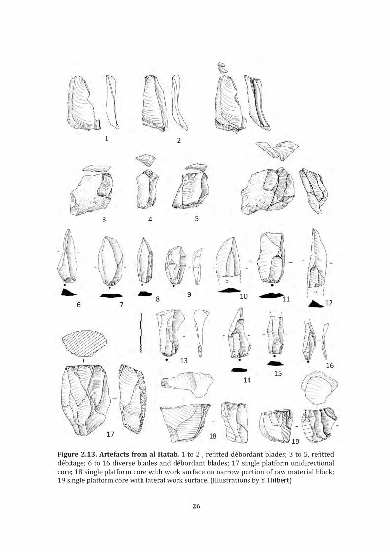
Figure 2.13. Artefacts from al Hatab. 1 to 2 , refitted débordant blades; 3 to 5, refitted débitage; 6 to 16 diverse blades and débordant blades; 17 single platform unidirectional core; 18 single platform core with work surface on narrow portion of raw material block; 19 single platform core with lateral work surface. (Illustrations by Y. Hilbert)
1 2
3 4 5
6 78 9 10 11 12
13
1415
16
17 1819

27
Flakes, blades and chert nodules have been modified into both formal and
informal tools. Formal tools are recognized by a repetitive pattern of shape and/or retouch
including burins, endscrapers, heavy sidescrapers, perforators, and bifacial foliates
(Figure 2.14). While burins show some degree of variability, the majority of these tools
were manufactured on blades. Most often at al Hatab, the characteristic “burin blow” was
administered along the long-axis of the blank, struck from a specially prepared truncation.
Also found within the assemblage are two tanged projectile point, one in each level. These
points show no intentional modification other than the peduncle (tanged) hafting element
at its base, a form resembling the “Fasad point,” which is thought to characterise the Early
Holocene in southern Arabia (Charpentier 2008). A variety of bifacial implements have
also been excavated from both levels at al Hatab (total n=10). These are made by hard
hammer percussion and display a variety of shapes and cross sections. Commonly, these
are biconvex in cross section and of oval to elongated in shape. Notably, they are cruder
in manufacture and do not share the thin, lenticular cross-section that characterise the
“Khasfian” bifacial foliates described in Rose (2006).
The similarities between these two levels cannot be explained by post
depositional mixing. Given the clear differentiation within the sediments in which these
two archaeological horizons were excavated, level 1 being related to the mechanical break
down of the roof and back of the shelter, while level 2 is found within overbank fluvial
deposits. It is unlikely that these artefact were produced elsewhere and brought to the
site by fluvial activity and/or slope waste. Thus, we interpret the OSL and AMS dates to
indicate that the site was visited intermittently between 14 and 10 ka BP, suggesting a
more or less continuous occupation across the Pleistocene-Holocene boundary in Dhofar.

28
Figure 2.14 al Hatab Tools. 1 to 5, diverse burins on truncation; 6 retouched blank; 7 partially retouched point; 8 Fasad point ; 9 and 10, biface. (Illustrations by Dr. V. Usik and W. Spring).
2.4 Summary
From this review, three basic observations can be made: (a) evidence for occupation
of southern Arabia during MIS 3 and 2 is scarce but present; (b) the technological and
typological packages found across southern Arabia are unlike that of its adjacent regions
(a.i. Levant, Africa and Asia); (c) there is a techno-typological discrepancy between Faya
NE-1 assemblage A site and the sites situated in the South Arabian Highlands.

29
While the lithic industry uncovered at Jebel Faya assemblage A has no parallels
anywhere inside or outside Arabia, the SD1/SD2 and al Hatab assemblages share a
specific blade technology. The archaeological finds from Dhofar and western Yemen are
not individual cases and may be related to a pan-southern Arabian leptolithic tradition.
Blade assemblages have been found across the Hadhramaut and Dhofar (e.g. Amirkhanov,
1994; Rose, 2006; Crassard, 2007; Hilbert et al., 2012), while further extensive scatters
have been recorded in central Oman and the Rub al Khaly desert (e.g. Biagi, 1994; Jagher
et al., 2011). To which extent these blade assemblages were coeval still remains to be
determined. Given that the majority of these sites are surface scatters chronological
attribution has to be done in relation to climatic events visible on the landscape and the
findscatters themselves. The next chapter will explore the climate record of southern
Arabia in order to establish a succession of dry and wet phases in order to determined a
relative chronology for the archaeological record.
Although al Hatab, Shi’bat Dihya 1, and Faya NE-1 assemblage A have been found
in different regions of South Arabia and most likely represent different technocultural
units, they all share one thing in common: their deposition did not occur during a wet
phase. In considering the temporal ranges of these assemblages, it should be stressed that
they were all dated using OSL, which does not provide a direct age of the archaeological
occupation, and rather gives a minimum age for the deposition of the sediments in which
the artefacts were buried. This limits our ability to draw conclusions regarding the
significance of these sites, other than their technological description and rough timeframe
during different phases of MIS 3 and MIS 2.
As aforementioned these sites and their assemblages provide a valuable frame of
reference for the many surface sites found in Arabia. Despite the wide differences in age, the
persistence of a laminar technological component throughout the South Arabian Highlands
indicates some degree of technological continuity between the human occupation found at
Shi’bat Dihya, and later occupation excavated al Hatab. The sites presented in this chapter

30
have almost nothing in common with any other techno/typological complex outside of
Arabia, suggesting the development of autochthonous lithic industries regardless of the
climatic conditions governing the peninsula.
The perusal of a possible continues human occupation across Southern Arabia
calls for certain questions and estimations. Namely how variable is the Late Palaeolithic
record across Arabia? Does the Late Palaeolithic of Arabia have a local or exogenous source?
And ultimately what happened to it? Did the local Early Holocene communities of Dhofar
independently developed “Neolithic” subsistence strategies or did populations carrying
these new technologies replace them? The majority of these questions are based on the
premise that population continuity is possible within climatic refugia and that population
continuity causes some degree of material cultural stability, which is detectable through
lithic analysis. Stability within the material cultural record means that decedents of a
given population, archaeologically represented by a lithic industry, will show a techno/
typological package comparable to the package of their ancestors. While this discussion
may be further explored by analysing new assemblages, the issue involving the climatic
oscillations can be elucidated by a review of the South Arabian paleoclimate.

31
Chapter 3
CLIMATE FRAME AND DATA FOR SOUTH ARABIA
Evans and O’Connor defined climate as the interplay of cool and warm air masses,
variation in pressure and humidity, local topography, latitude and global hydrosphere,
whether in the form of oceanic water or polar ice (Evans & O´Connor, 1999, 12-13). The
following background chapter will explore the interplay between the diverse features
named above and synthesise the available climate data of Southern Arabia. From the
review of the archaeological record presented in chapter Two, it is obvious that the Arabian
paleo-climate was subjected to oscillations during the Pleistocene. These oscillations had
some effect on the indigenous populations, possibly constraining their habitat during
climatic downturns. During periods of amelioration the Arabian landscape carrying
capacity increases, allowing expansion from within and possibly outside of the Peninsula
to spread across its landscapes. The perusal of the paleo-climatic record of Arabia may
help to established how intense these climatic oscillations have been and whether
climatic downturns were inevitably responsible for population discontinuity across the
Late Pleistocene.
The published record of Arabia’s paleo-climatic history is rich and manifold (e.g.
McClure 1976; 1978; 1984; 1988; Burns et al., 1998, 2001; Neff, 2001; Preusser et al.,
2002; Parker et al., 2006b; Parker, 2009; Rose, 2006; Rose & Parker, 2008; Fleitmann et al.,
2004, 2007; Hoorn & Cremaschi 2004, Cremaschi & Negrino 2005; Beineke, 2006; Lézine
et al., 2007; Fleitmann &Matter, 2009; Preusser, 2009; Parton et al., 2010; Rosenberg et al.,
2012). It has been pointed out that the emphasis in Arabian climate research has favoured
the reconstruction of the terminal Pleistocene and Holocene environments (Fleitmann
et al., 2003; Parker, 2009). Over the past decade mid- to late Pleistocene environmental

32
reconstruction based on terrestrial records have contributed to an increasingly complex
account of Arabia’s environmental history. The inaccessibility of some key areas in the
Arabian Peninsula and the destructive depositional character of its sediments, however,
still hamper the advance of climate research in the peninsula.
Over the next pages diverse data sets, the deep-see-cores and ice-cores, terrestrial
records, lacustrine deposits, pollen diagrams and alluvial features, will be presented
and discussed as to their implications on the reconstruction of past climatic events. The
Indian Ocean Monsoon, South Arabia’s main weather system will be discussed regarding
its periodicity and intensity. Special attention will be given to the impact this major
force has on Southern Arabia. A short synthesis of Arabian paleoclimate based on the
available literature will follow. In this chapter’s summary the relations between climatic
deterioration, population demographics and environmental deterministic models, such as
the tabula rasa, will be discussed.
3.1 The Marine record
Global climate is dictated, among other elements, by the disposition and amount
of water available in the earth’s weather system. A major role in this equation is played by
the expansion and retreat of glaciers in the northern and southern hemispheres during
cooler climatic phases. These glacial phases had great influence on the global climate given
that they trapped large quantities of water within the glaciers across the planet. Indirect
evidence for climate changes is provided by continuous deep-sea cores and their O¹⁸ and
O¹⁶ isotopic values. During glacial periods, evaporated water containing the lighter O¹⁶
isotope becomes trapped within glaciers, leaving the oceans with a higher concentration
of the heavier O18 Isotope. The O¹⁶ and O¹⁸ isotope ratios become incorporated in the
carbonated skeleton of deep-sea foraminifers that build up the ocean floor sediments.
By analysing the O¹⁶ and O¹⁸ ratios of deep-sea cores, the intensity and periodicity of
glacial and interglacial periods can be estimated. The global Marine Isotope Stage (MIS)

33
sequence consists of even number, representing glacial periods, and uneven number,
representing interglacial or warm phases. The MIS may also been detected on the basis
of ice cores retrieved from the North and South Poles (Webb & Bartlein, 1992; Petit et al.,
1999; Waerlbroeck et al., 2008).
Deep-sea cores relevant for the review at hand were retrieved from the coasts of
Oman, Yemen, the Strait of Hormuz, the north west and east of the Indian Ocean (Schulz
et al., 1998; van Rad et al., 1999; Leuschner & Sirocko, 2000; 2003). The marine cores
provide data that helps understand greater global climatic phenomena. Additionally the
driving forces behind the major weather system acting on the area in focus, the IOM, are
elucidated (Clemens et al., 1991).
Marine sedimentation dynamics in the Arabian Sea are dictated by the seasonality
of the south western and north eastern monsoons. The south western monsoon-induced
upwelling on the South Arabian coast influences the bio-productivity of the Arabian Sea
(Ivanochko, 2004; Schulz et al., 2002a; 2002b; Saher et al., 2007). Indices of bio-productivity
may be used to measure monsoonal intensity over the time spam of the last decades and
beyond. Data on sedimentation rates under present conditions provide scientists with
valuable information when analysing older deep sea sediment cores.
The inversion of the atmospheric pressure zone over the Arabian Peninsula
across the summer and winter months additionally affects marine productivity and
terrestrial climate conditions. During summer months the temperature over the Arabian
Peninsula is higher than the temperature over the sea surface, causing the activation of
south westerly winds bringing in moisture from the sea into South Arabia. The inverse
condition is observed during winter months, when seawater surface temperatures are
higher that over the Arabian land mass, causing dry north-eastern winds to blow toward
the ocean (Zarins, 2001: 22). Past changes in the Earth’s orbit and solar radiation have
greatly influenced the dynamics over the Arabian Peninsula causing a drastic increase in
monsoonal intensity (Clemens et al., 1991; Lézine et al., 1998; Lauchner & Sirocko, 2003).

34
This increase results in higher precipitation levels, which influence the landscape carrying
capacity across the area.
The Intertropical Convergent Zone (ITCZ), which may be described as a narrow
convergent wind and precipitation zone that dictates the onset, periodicity and strength
of the rainfall in tropical zones, additionally played a role in the weather dynamics over
South Arabia (Fleitmann et al., 2007; 2011). Under present conditions, the ITCZ and
its associated precipitation belt rests south of the equator during winter months. This
condition and the high pressure cells over the Eurasian continent result in moderate
north eastern winds over the Indian Ocean. Due to the heating of the northern tropical
and subtropical continental landmasses during spring, the ITCZ migrates northward
resulting in a pressure inversion, causing a shift in the wind regimes over the Indian Ocean
(Figure 3.1). The south westerly winds bring in considerable amount of moisture from
the equatorial zone, which is released over the northern Indian Ocean and subsequently
South Arabia.
Figure 3.1 Migration of Indian Ocean Monsoon. In part 1 of the image the position of the IOM during the summer months is depicted while is part 2 the position during he winter months is shown. The dotted line represents the Inter Tropical Convergence Zone. Arrows in the image indicate the directionality of the prevailing wind regimes. (After Fleitmann et al., 2004, fig. 1)

35
Further implications of the northward migration of the ITCZ during the onset of
the Holocene may be seen in speleothems from three different sites in Yemen (Socotra)
and Oman (Dhofar and Hajar Mountains). Based on four sampled localities researchers
were able to track the migration of this weather-forcing agent by means of dating cave
speleothem growth (using Th-U dating methods1). Speleothem growth provides a reliable
indicator for both constant and periodic rainfalls. According to this study the mean
latitudinal position of the ITCZ and its associated rain belt rapidly migrated northwards
during the early Holocene. Over the course of the mid Holocene, however the ITCZ
gradually migrated back southward as a response to solar insolation; causing decrease
in precipitation and shortening of the summer monsoon phases (Fleitmann et al., 2007).
The ice cores, deep sea cores and other marine data sets are key elements,
helping scientists to understand fluctuations and periodicities of the earth’s climate. Ice
cores allow scientists the measure the content of green house gases in the atmosphere
and the detection of rapid climate fluctuations (Orembelli et al., 2010). Deep sea cores
give information’s regarding climatic fluctuations in the northern hemisphere and their
effect on low-latitude monsoonal climate variability. Both data sets help shed light on
global forcing agents such as green house gasses and atmospheric moisture (Schulz et al
1998). These agents have great affect on global climate; however, in order to understand
the imprint they have on a more regional scale the investigation of local dynamics are
needed. The climate fluctuations over southern Arabia are a response to diverse factors,
as has been see a major role in this equation is played by the IOM and the migration of the
ITCZ. These elements will therefore be further discussed over the next pages.
3.2 The Indian Ocean Monsoon
The Indian Ocean Monsoon (IOM) is the principal weather agent acting over
1 The Uranium Thorium dating method is a radiometric dating method used to date calcium carbonates, such as cave speleothems and flowstones. Based on the detection by mass spectrometry of the Uranium (²³⁴U) and Thorium (²³⁰Th) products of decay and calculating the initial amount of both elements in the sample an absolute age for the carbonates can be obtained (Neff, 2001).

36
the Indian Ocean and the Arabian Sea. Its impact over South-West Asia, Arabia and the
Horn of Africa is great under present conditions and was presumably also fundamental
for prehistoric populations living in those regions during the Pleistocene. Understanding
the elements governing the IOM under present conditions is of vital importance for
comprehension of its past dynamics.
Forcing factors of the IOM intensity and periodicity are, after Clemens et al.,
(1991) mainly related to insolation and heating of the continental and oceanic masses.
Variations in the earth’s obliquity and processional orbit, the availability of latent heat
and the amount of continental albedo, which is linked to the intensity and duration in
continental glaciations, are further agents impelling monsoonal strength. According to
Clemens and his team a strong relation between global insolation and the inclination of
the Earth’s axis during its orbit around the sun can be inferred. An equally fundamental
part is played by the transport and availability of latent heat over the equatorial belt. In
the case of the IOM this part is played by the accumulation and release of heat over the
Asian Plateau (Clemens et al., 1991, 725).
IOM peaks are related to solar radiation and its associated body of traits named
earlier, the interplay of the atmospheric, topographic and climatic traits may be read from
diverse lines of evidence. Deep sea cores bearing laminated layers have been collected
along the Arabian coast. The laminations within these cores are related to silica based
skeletons of planctonites foraminifera, mainly Globigerinoides ruber, Globigerina falconensis
and Globigerina bulloides (Schulz et al., 2002b). The presence and abundance of these
planctonites relates to different oceanic conditions. Productivity levels, post-depositional
and sedimentary factors dictate the presence of planctonites in marine sediment records.
In order to fully comprehend and draw conclusive data out of the marine cores
retrieved from the Arabian Sea, the sedimentation, suspension and transport factors
involved during monsoonal activity must be understood. The north eastern IOM creates
a low pressure zone over Pakistan and north India that draws the equatorial trade winds
37
and subsequently generates a strong low-pressure wind jet, called the Findlater Jet
stream, which blows parallel to the Arabian Peninsula (Rixen et al., 2000). This stream is
responsible for the disturbance of marine sediments along the Southern Arabian coast.
Schulz et al. (2002b) conducted investigations in the northern Arabian Sea off
the Pakistani coast. There the weather regime is dictated by the north eastern monsoon,
which is active during the winter months. Particle flux and plankton foraminifera samples
collected form sediment traps retrieved by Schulz and colleges helped to reconstruct the
seasonal intensity of both, south western and north eastern monsoons for the past 25
ka BP. The researchers conclude that Globigerina bulloides, a foraminifera related to the
south western summer upwelling showed little precipitation in the north eastern Arabian
Sea. Where as Globigerina falconensis, whish is a marker for winter like conditions, was
abundant in the north eastern Arabian Sea. Using the occurrences of these foraminifera,
the settings in which these two specimens occur and the factors that lead to their dispersal
across the Arabian Sea, Schulz et al. concludes that during MIS 2 the south western and
the north eastern monsoons acted independently from each other. During the Heinrich
Meltwater2 and the Younger Dryas event the north eastern monsoon was active while the
south western remained dormant. During the onset of the Holocene both systems become
activated and show levels of intensity above the ones presently observed (Figure 3.2).
In concordance with the data presented by Schulz and colleges, Ivanova et al.
(2003) demonstrates a similar pattern for earlier monsoonal activity discordances. Based
on foraminifera productivity ratios she and her team conclude that during MIS 1, 3 and 5
monsoonal related productivity peaks occurred induced by deep water upwelling. During
the transition between MIS 5 and 4 a high foraminifera productivity event in the northern
Arabian Sea may be marked, whereas the south western monsoon seems to show a low
activity phase (Ivanova et al., 2003, fig. 9).
2 Heinrich events are typical for the North Atlantic Ocean marine cores and are characterized by course grained materials found in oceanic sediments these sediments were caused by ice rafted debris related to massive iceberg discharges into the Atlantic Ocean. These events, which tool place every 10 ka years, had a cooling effect over the global climate (Claussen et al., 2003).

38
Figure 3.2 Monsoon intensity. The graph presents the intensity of the NE-Monsoon and SW- Monsoon in relation to each other. (After Schulz et al., 2002b, fig. 9)

39
The variability and periodicity of the IOM is liked to climatic oscillations that
take place in the northern hemisphere, such processes are known under the term
teleconnections. Glacial periods in the northern hemisphere and the IOM may relate to
higher rations of global insolation (Clemens et al., 1991; Leuchner & Sirocko, 2003; Neff,
2001; Neff et al., 2001). IOM intensity peaks coincides with northern hemisphere insolation
and decrees in glacial ice volumes, therefore this climate agent is of great importance
when analysing changes and variability in the Earth climatic history. In a millennial scale,
monsoonal variations seem to be related to insolation forced pressure gradients over the
central Asian plateau and the Indian Ocean (Leuschner & Sirocko, 2003).
The data and research presented here marks the Earth’s climate as one
interconnected system. The tendencies observed in the Arabian and Indian Ocean
marine records indicate a strong relation between pressure zones, wind regimes, ice
sheet extends and global insolation (Clemens et al., 1991; Schultz et al., 2002; Ivanova et
al., 2003; Leuschner & Sirocko, 2003). The data discusses here indicates that there are
subtle differenced in the south western and north eastern IOM regimes. This difference
in monsoonal intensity over the Late Pleistocene probably influenced the archaeological
record. The dissimilar archaeological pattern expressed by the Shi’bat Dihya and Jebel Faya
NE-1 assemblages may related to two different populations inhabiting two different areas
affected by diverging weather systems. In order to measure the impact of the different
Monsoonal regimes on the Southern Arabian landscape, and test the demographic
implications indicated above, one has to turn his attention to the terrestrial record of this
region.
3.3 The terrestrial records
The terrestrial climate record for Arabia is manifold; (a) ancient lake profiles
that aside from giving information on wet phases may provide important pollen data (e.g.
McCLure, 1976; 1978; Parker et al., 2004; 2006a; 2006b; Lézine et al., 2007; McLaren et

40
al., 2009; Parton et al., 2010); (b) speleothem calcites, giving additional data on wet spells,
variations between winter and summer precipitation rates and average temperatures
(e.g. Burns et al., 1998; Fleitmann et al., 2003, 2004 and 2007; Fleitmann & Matter,
2009); (c) eolian sediments that may be dated using Optical Stimulated Luminescence3
(OSL), providing information about changes in wind regimes and sediment availability
(e.g. Stokes & Bray, 2005; Glennie & Singhvi, 2002); (d) cave deposits (e.g. Cremaschi &
Negrino, 2005; Immenhauser et al., 2007); (e) inland alluvial fans (e.g Blechschmidt et al.,
2009); and (f) coastal sediment deposits (e.g. Hoorn & Cremaschi, 2004).
Eolian environments make up most of the desert landscape in South Arabia.
According to Holms (1960), approximately one third of the Arabian Peninsula is covered
with sand; the Rub al Khali alone covers approximately 600.000 square kilometres of the
1.7 mil square kilometres of the Arabian Peninsula. Sand dune movements are chiefly
dictated by local wind regimes. Arabia’s eolian environments are dictated by two diachronic
wind systems sweeping over the landscape in the past and under present conditions. The
Shamal winds, mainly a winter phenomenon, blow down the Arabian Gulf and reaching
the Emirates turn clockwise towards the Rub al Khali desert and the peninsulas interior.
The south western monsoon winds blow from the African continent towards the Indian
sub-continent and on their way sweep past the South Arabian coast line, passing over the
Wahiba Sand and reaching the Omani Mountains. Those winds blow during the summer
months and are responsible for sporadic torrential thunderstorms in the north of Oman
(Glennie & Singhvi, 2002).
The origin of eolian sediments provides critical data on the variability of the wind
systems over the Arabian Peninsula through time and the disposition of the landscape
itself. During the Late Glacial Maximum (LGM) the global sea levels dropped due to the
3 This dating method makes use of the electrons trapped within the crystalline structure of quartz, feldspate or aluminum oxide grains in sediments or archaeological materials such as pottery and burnt flint. These electrons become exited by solar radiation or heat. Under controlled laboratory conditions, the electrons in a given sample become stimulated again causing them to emanate light. The photons are then detected using a photomultiplier tube. This device calculates the dose the sample had observed. It is then possible to infer the samples last exposure to sunlight or intense heat (Aitken, 1998).

41
amount of water trapped within the Earth’s glaciers. Given the shallow depth of the
Arabian Gulf, a great portion of this area became emerged. This area was dissected by the
paleo-Tigris and Euphrates river basins (Lambeck, 1996). The dry sea bed would have
been a prolific source of eolian sediments (Glennie & Singhvi, 2002).
In contrast to the notion of the dry Gulf being the source of unconsolidated sediment
during the LGM, Stockes and Bray (2005) argue in favour of a divergence between sea level
change and sediment supply. Based on OSL dates from paleo-dunes, test pits and exposed
paleo-dune profiles, the researchers concluded that eolian sediment accumulation in the
Liwa and Al Qafa regions of the Emirate of Abu Dhabi took place during MIS 5 (ca.75-
130ka) and MIS 1 (ca. 2-6 ka). Little evidence for eolian activity during MIS 2-4 could
be found. This could be due to an extensive organic cover over the emerged Gulf-Oasis,
which hampered sediment transport by eolian means. Combined with the north eastern
monsoonal evidence, the eolian terrestrial record provides support for the Gulf-Oasis
Hypothesis (Rose, 2010). Likely this region served as a refugia for human populations
living in the area during MIS 4 and 2.
Using dune size indices, Warren and Alison (1998) reconstruct the paleo-wind
regimes that shaped the Wahiba Sands in the north east of Oman. This sand desert,
approximately 10.000 km2 in size, is characterized by linear dunes with up to 60 metres in
height oriented at a south to north axis (Figure 3.3). The researchers suggest that dune size
is not related to wind intensity and sediment supply only. The periodicity of the weather
regime that gave rise to the winds acting on central coastal Oman also played a considerable
role in the emergence of the Wahiba Sands. Wind cycles trigger diurnal phases of eolian
activity, these cycles coupled with sufficient sediments appropriate for wind transport
lead to dunal displacement, growth or destruction. Past three metres of height, dunes
become susceptible to destruction or redeposition. In order to remain developing in size
a constant weather system are needed. Changes in global climate caused by oscillations
in the Earth’s obliquity, eccentricity and precession deeply influence the consistency of

42
regional wind regimes. Mega-dunes, as observed in the Wahiba Sands, occur because
of long constant phases presenting the same climate or a series of successive, similarly
manifested, phases with the same climate. Mega dunes accumulated in the Wahiba during
the LGM, according to this theory.
Figure 3.3 Linear dunes at the Wahiba Sands, Oman. (Photograph by Y. Hilbert)
Seashell fragments detected in the lithology of the Wahiba Sands sediments
indicates a marine origin, the now submerged Omani continental shelf being the most
probable source of the eolian sediments (Radies et al., 2004). Eolian sediment aggregation
appears to coincide with global low sea level periods. Given the marine environment and
the northward migration of the ITCZ during favourable phases, sediment preservation as
opposed to further transportation was hampered by punctuated wet spells during MIS 6
and 5. These events were responsible for dune stabilization and soil formation processes in
the central Oman. OSL dating on eolian deposits in the area show four phases of deposition,
MIS 1 (10 ka ± 4, 10 ka ± 1), MIS 2 (18 ka ±, 23 ka ±3), early MIS 5 (110 ka ± 11, 117ka ±12,

43
112 ka ± 12) and MIS 7 (229 ka ± 19) (Juyal et al., 2006). Additional OSL dating provided
by Preusser (2009) indicates further eolian accumulation during MIS 6, 5b, 5d, 4 and
increased activity between 3-1, with a peak during the LGM. Apparently eolian sediment
deposition in the Rub al Khali desert and the Wahiba sands were synchronous during dryer
phases of both MIS 6 (186-130ka) and MIS 5d (115-106ka). The lack of eolian deposition
in the Rub al Khali dating to that period may be related to absence of unconsolidated
sediment and their constant redeposition. Probably sediment stabilization related to an
extensive grass cover in the Arabian Gulf Oasis, or cementation of the sediments during
this period would have hampered eolian sediment transport making up for the lack of
deposits dating to the MIS 4 and 2 in central Arabia (Lambeck, 1996; Teller et al., 2000).
The accumulation of eolian sediment in central Oman and the Rub al Khali formed a desert
that may have acted as a barrier hampering human movements between the Gulf Oasis
and the South Arabian Highlands.
Fresh water lake deposits provide indirect evidence for wet phases across Arabia.
McClure published some of the early radiometric dates on lake deposits in Arabia (McClure,
1976). The set of dates acquired from the fossils lakes in the Mundafa area in southern
Saudi Arabia suggests two main phases of lacustrine deposits. The relatively recent
deflation of the surface uncovered approximately twenty-eight metres of lake deposits
consisting of calcareous and fossiliferous marl layers interstratified with eolian deposits.
The two major depositional events were identified based on geomorphological aspects and
radiometric dating methods. The lowest lacustrine deposit rest on top of alluvial deposits
and date roughly to MIS 3, with a peak in deposition between 30 and 21 ka BP. These lake
sediments are covered by eolian sands, which in turn are covered by a second lacustrine
deposit dating to the early Holocene, 9 and 6 ka BP. Additional lake sediments have been
recorded by Schulz and Whitney (1986) in the An Nafud region in northern Arabia. The
sediment sequence is similar to the sequence described by McClure. The early lake phase
consists of calcareous marl interbedet with eolian sediments dating between 8.4 and 5.4

44
ka BP. The lower lake sequences are Late Pleistocene in age and dates between 34.000 and
24.000 BP based on radiocarbon dates. Additional dates on lake sediments from Arabia
come from a site called Al-Quwaiayh in central Saudi Arabia. McLaren and her research
team (McLaren et al., 2009) have produced OSL dated on fluvial deposits associated with
lacustrine accumulations. The lake deposits have formed during more humid phases
of the late Pleistocene, around 54 ka (MIS 3). The aggregation of lacustrine deposits in
central Saudi is indicative of improved climatic conditions occurring across Arabia during
MIS 3. Parallel to these discoveries in Parton et al. (2010) have uncovered a lake sequence
close to Jebel Akhaba in the Emirate of Sharjah. The lake sequence uncovered at Akhaba
presents successive aggregation and desiccation events going back to the MIS 6. Parton
et al. identified a fluvial episode marked by gravels at 56 ka BP, MIS 3, roughly coinciding
with the result from Saudi Arabia.
The geomorphology of South Arabia, with the Red Sea basin and the Arabian
Shield to the west and the Hadhramaut and Dhofar Plateau to the south, may explain why
during wet periods the IOM seldom reached the inland zones (Lézine et al., 2007). The
topography may have functioned as a moisture trap, causing the discharge of rainfall over
these regions. Late Pleistocene and early Holocene lakes in Yemen (Davies, 2006; Lézine
et al., 2007), central Saudi Arabia (McClure, 1976, 1978; Schulz & Whitney, 1986) Oman
(Urban & Buerkert 2009) and the UEA (Parker et al., 2004, 2006a; 2006b; Parton et al.,
2010) support this assumption. In most of the sites the waters feeding the lacustrine
environments during the early Holocene (12-7 ka) derived from run-offs coming from
torrential seasonal precipitation in the mountains. Little evidence supports the notion
that constant inflow from persistent flowing riparian settings have fed the lacustrine
environments of Arabia. The lacustrine sediments are interlaced with eolian sediments, as
seen in the samples from Liwa in the Emirates, the Maqta site in the north of Oman and the
al-Hawa sediment series from Yemen. Such laminated sediments indicate that although
these lakes have been formed rapidly, they persisted and where slow to dry out.

45
Botanical data from South Arabia strengthens the notion of soil formation
processes during the early wet spells of the Holocene. A shift from C4 type vegetation
generally associated with a warm and dry climate, to a C3 vegetation that is related to a
savannah like humid and warm climate may be observed in localities across the Emirates
and Oman (Urban & Buerkert, 2009; Parker et al., 2004). This transition would have
stabilized the large bodies of eolian sediments that accumulated during the dry phases
and the short but rather strong sedimentation phase postdating the late Pleistocene to
Holocene transition, particularly the Younger Dryas4.
While most terrestrial climate records in Arabia are from paleolakes, which are
highly susceptible to C¹⁴ dating errors, cave speleothems may be accurately dated and
therefore provide high-resolution climate data (e.g Fleitmann et al., 2003; Preusser, 2009).
South Arabia provides a variety of cave and travertine environments from where such
information might be gathered. Karstic cave sequences from Dhofar, the north of Oman,
Yemen and Saudi Arabia have yielded valuable Speleothem climatic data (Burns et al.,
1998, 2002; Neff, 2001; Fleitmann et al., 2003; 2004; 2011; Fleitmann & Matter, 2009).
By measuring the oxygen (δ¹⁸O) and the hydrogen (δD) ratios of calcite
speleothems, and analysis of the fluid inclusions trapped within the stalactites, the source
of moisture and the respective intensity of wet spells over Arabia may be detected. Given
the dating advantage of cave speleothems over lake deposits5, tracking wet spells by means
of identifying speleothem growth periods as opposed to growth stagnation may provide
continuous climatic data for South Arabia (Neff, 2001; Fleitmann & Matter, 2009).
A series of eleven stalactites from Dhofar and Northern Oman were analysed in
order to create a reliable data set used to determine the dynamics of the IOM and the
4 The Younger Dryas, or „Big Freeze“, comprises a relatively short phase of approximately 1.300 years of cold climatic conditions in the temperate zones and severe drought across Africa and Arabia. This period of Rapid global climate change took place between 12.900 and 10.000 Bp.
5 Speleothems may be dated using Th-U method, by which samples older then 500ka may be dated, whereas lake deposits are traditionally dated using the C¹⁴ method which becomes highly incurred when the samples surpass the 40ka age barrier.

46
subsequent migration of the ITCZ. Speleothem growth phases and the isotopic signature
of these samples provide further information on the periodicities and paucities of wet
spells in South Arabia. Given that speleothems growth phases require moisture that
seeps through cave systems, displacing and redepositing calcite on its way, Fleitmann
and Matter identified five wet phases over the past 330 ka. These were interrupted by
long periods of growth stagnation, phases where little to no moisture was present in the
regions hydrology. Speleothem deposition coincided with interglacial periods related to
the (Holocene, MIS 5a, 5e, MSI 7a and MIS 9. Speleothem growth seemed to follow phases
of deglaciations in the northern hemisphere, pointing to maximum solar insolation and
minimum glacial extent leading to subsequent albedo, forcing the IOM to discharge high
amounts of moisture over southern Arabia.
Analysis of the speleothems from Hoti Cave (northern Oman) dating to the last
interglacial (5e) revealed relatively low ¹⁸O values, as opposed to the δ¹⁸O water values
recorded under present conditions further inland. The current sources of moisture in
northern Oman are mainly the Northwesterly winds that blow down the Arabian Gulf
bringing in moisture from the Mediterranean. The negative isotopic values identified in the
Hoti Cave speleothems during the period between from 130 to 120 ka suggest a different
source of moisture for this period. Negative isotopic values are recorded in regions where
the main source of water derives from monsoonal rains, like the tropical parts of India and
south East Asia. It is therefore feasible that the recorded values in north Oman are related
to a northward migration of the mean latitudinal position of the ITCZ as it was suggested
for the early Holocene wet phase (Figure 3.4) (Burns et al 1998; Fleitmann et al 2007;
Fleitmann & Matter 2009).
Climatic data presented here consists of a fraction of what is available. The
increasing interest in Arabia’s paleoenvironments and archaeology generates a fair
amount of information every year. The data presented above represents a compromise of
older and newer proxy data available for Arabia.

47
Figure 3.4 Northward migration of the ITCZ. In the maps above depict the position of the ITCZ during its northernmost reach within a year cycle for dry phases (left) and wet phases (right). (After Neff, 2001, fig. 4.5)
3.4 Summary
Intensity and paucity of wet and dry spells have affected the landscape in very
distinct ways. During periods of environmental deterioration, depending on local wind
regimes, the overall availability and disposition of eolian sediments, the accumulation
of sand seas like the Nafud, Wahiba and Rub al Khali desert took place. During phases
of environmental restoration, induced by both global and solar agents, the northward
migration of the mean latitudinal position of the ITCZ would bring in considerable
amounts of moisture to South Arabia. Coupled with the rise of global ocean water level
and subsequent rise of the ground water level in South Arabia during pluvial phases
increase in precipitation would have triggered a landscape reactivation event visible in
the diverse terrestrial climate records (Figure 3.5). These landscape activation phases had
great affect on human populations and subsequently, the archaeological record. The focus
of the following discussion is the integration of the climatic data presented here with the
review of the archaeological record presented in chapter Two.

48
During periods of climate amelioration, South Arabia was considerably wetter
than under present conditions. The reactivation of dormant springs would feed the once
seasonally active wadis. These would run year round given the rise of the ground water
level. The consequences of this would be a shift from a deserted rocky landscape to a
Highland savannah across southern Arabia. The increase in moisture would serve as a
temperature regulation agent and further increase precipitation. Following the advance
of this savannah-like flora, medium to large herbivore populations would procreate
and expand, attracting top predators like Panthera pardus (Leopard), Acinonyx jubattus
(Cheetah) and Homo sapiens.
Figure 3.5 Sum probability curve fort eh Late Pleistocene of Arabia. (Parker & Rose, 2008, fig. 4)

49
While environmental amelioration was relatively fast-paced in South Arabia,
southward migration of the ITCZ and subsequent climatic deterioration of inhabitable
landscapes occurred over longer periods (e.g. Beineke, 2006; Fleitmann et al., 2007;
Fleitmann & Matter 2009). Gradually, as the Monsoonal belt drifts southward, desertification
advances. The ground water levels sink and the rare seasonal storms cause the erosional
depletion of the available soils and the transport of piedmont debris creating large alluvial
fans in the inland of South Arabia. Those factors had great influence on the character of
the archaeological record of Arabia, which is marked by artefact surface scatters that have
once been buried.
With the erosion of the fertile soil cover the savannah grassland gives way to
arid adapted scrubs. The biomass, including human groups, contract into refugia, like
the Dhofar Mountains in the south, the Red Sea Basin to the west or the Arabian Gulf
(Parker & Rose, 2008; Bailey, 2009; Fedele, 2009; Rose & Petraglia, 2009; Rose, 2010).
The expansion and contraction of this semiarid belt and the conjectured movements of
the human groups expanding within those regions is of relevance to understanding the
archaeological material present in the diverse ecological zones of Southern Arabia. The
archaeological background presented in chapter Two focused on sites dating to the MIS
3. Based on the investigation of the lithic technology and stone tool spectrum researchers
postulated local origins for the industries uncovered at Jebel Faya NE-1 and Shi’bat Dihya
(Armitage et al., 2011; Delagnes et al., 2012). This implies that these populations are
descendent of human groups that expanded into Arabia during or before MIS 4.
Climate proxies for MIS 6 consist of eolian accumulation dated by OSL method in
the Liwa region of the Rub al Khali and the Wahiba sands, indicating that this period was
marked by dry and inhospitable conditions (Preusser et al., 2002; Radies et al., 2004).
Population movements into the Peninsula recorded for the MIS 6 are non-existent, nor
are any archaeological sites dating to this period known in Arabia. Following the climatic
pattern of global amelioration triggered by the retreat of the northern hemisphere glaciers,

50
the increase in solar insolation and the rise of global sea level, the last interglacial in South
Arabia is marked by phases of increased precipitation. The northward migration of the
IOM precipitation belt may be held responsible for an expansion of the savannah belt
across South Arabia. The speleothem record of northern Oman signals a major wet phase
at the onsets of the last interglacial that appears to have been stronger than the post-
dating pluvial events in the course of the quaternary (Burns et al, 1998; 2001; Fleitmann
& Matter 2009). Between 130 and 120 ka BP (MIS 5e) the ITCZ migrated northward
bringing in substantial amount of rain to the Arabian Peninsula, causing a stabilization of
the eolian bodies and ceasing dune accumulations.
Archaeologists working across Southern Arabia believe that Anatomical Modern
Humans (AMH) left Africa and expanded into Arabia during the onset of the MIS 5 pluvial
phase. Although human remains attesting this hypothesis have not been found yet, the
archaeological evidence uncovered at Faya NE-1 presents general African traits (Armitage
et al., 2011, 455) hinting at possible connections between assemblage C and East Africa.
A stronger case is provided by the presence of Nubian technology found in Dhofar dating
to the MIS 5c (Rose et al., 2011; Usik et al., 2012). Both discoveries point to Africa as the
source of human populations living in Arabia during MIS 5.
It has been argued that the transition between MIS 5 to 4 was triggered by the
mega eruption of the Toba Volcano. This catastrophic event is thought to have plunged
global climate into a volcanic winter that lasted several years, possibly decimated human
populations living outside of isolated refugia (e.g. Ambrose, 1998; Steward & Stringer,
2012). Contrary opinions have been uttered by many scholars regarding the impact of
this event on both climate and human evolution (Schulz et al., 2002a; Oppenheimer,
2002; Gathorne-Hardy & Harcourt-Smith, 2003; Petraglia et al., 2007). One of the main
arguments brought by Schulz et al. (1998, 2002b) is that the onset of glacial conditions and
their further development showed little susceptibility to the Toba “super eruption”. Global
climate was shifting towards glacial condition before the Toba eruption happened. Arabia

51
climate during MIS 4 was marked by dry condition, the ceasing of speleothem growth
and eolian accumulation in the Wahiba Sands represented by four IRSL dates clustering
between 79.9 ±7.6 ka and 63±4 ka BP(Radies et al., 2004) support this notion. Also, the
onset of a super dry phase recorded in Africa by 74 ka, visible in the maximum extension
of the Sahara and the Kalahari Desert (Bahrman & Mitchels, 2008) may be noted here.
In general the overall lack of data from MIS 4 (Parker, 2009) hampers interpretations
regarding the extent of this phase throughout Arabia. While archaeological sites dating
to the MIS 4 are unknown in southern Arabia, Usik et al. (2012) explore the possibility of
a persistence of the Dhofar Nubian Complex across the MIS 5 and MIS 4. This persistence
is visible on the basis of technological continuity of the Nubian reduction method and its
use during the Mudayyan industry. Additional data supporting the persistence of human
occupation across southern Arabia comes from Jebel Faya NE-1 assemblage B, which
possibly represents the source for assemblage A (Armitage et al., 2011).
The MIS 3 wet phase is signalized by a diverse set of paleoenvironmental data.
While there seems to be little resonance of this phase in the speleothem and marine records
of Arabia, researchers have reported a large number of lacustrine deposits throughout
the interior of the Peninsula. Whereas most of those lakes, which have been dated using
fervently disputed C¹⁴ samples from fresh water molluscs (Preusser, 2009; Parker, 2009;
Wilkinson, 2009), cluster around 30-21 ka and 34-24 ka BP, newly acquired dates from
Saudi Arabia obtained using the OSL method yielded a lacustrine phase dating to the
early MIS 3 (53-39 ka). Marine records support the notion that MIS 3 fluctuated between
periods of aridity and increased precipitation (Schulz et al., 1998; Beineke, 2006). The
actual imprints of those fluctuations during MIS 3 on the South Arabian climate record
seem to be manifested by the reactivation of the older Pliocene and Pleistocene riparian
systems culminating in the accumulation of large bodies of water in depressions within
the landscape. Given the sedimentary scope of the lakes identified in the Rub al Khali,
Beineke (2006) concludes that these would have formed relatively fast and were slow

52
to dry out. Varying greatly in size, these lakes would have offered both flora and fauna
sufficient moisture to transform the immediate surroundings of those environments into
semiarid savannahs. Dating of fossil groundwater from Saudi Arabia and central Oman
have the accumulation of rain waters between 24,630±500 BP and 20,400±500 BP for the
western Rub al Khali and 30 KA BP to 20 Ka BP for the Nejd Plateau (Ibid. 54). Landscape
revival around these lakes would have been short lived, as stated above. Nonetheless,
archaeological evidence for MIS 3 in Arabia is consistent and shows, as has been stated
in chapter Two, some variability. This variability may relate to two different populations
living in separate refugia; one in the Gulf and one in western Yemen.
The last glacial period in Arabia is marked by a drastic sea level drop and intense
eolian reactivation. Signs of this arid phase are visible in the marine record, showing a
decrease in the south western monsoonal activity (Schulz et al., 1998; Leuschner & Sirocko,
2000, 2003), and increase in north eastern winter Monsoonal conditions (Schulz et al.,
2002b). Eolian reactivation is principally observed in the Wahiba Sands and in the marine
sediment cores. Here the changes in wind pattern induced by the southward migration
of the ITCZ are visible in the linear deposition of mega dunes in this region (Warren &
Alison, 1998; Glennie & Singhvi, 2002; Preusser et al., 2002). Evidence for a short-lived
wet phase during MIS 2 has been summarized by Parker (2009). Marine records from the
northern Indian Ocean, off the coast of Pakistan show an oscillating regional record for the
glacial/interglacial transition in concordance with the H1 event (Heinrich) in the northern
latitudes (Schulz et al., 1998 fig. 3). Speleothem growths dating back to 15,78±0.15 KA BP
from the Summan-Plateau in Saudi Arabia and travertine deposits from the Nizwa region,
Oman, dated between 16.3 and 13 ka BP, indicate the presence of some regionally specific
wet phenomena around the Later LGM (Fleitmann et al., 2004; Clark & Fontes, 1990). This
period was then again interrupted by the onset of the Pleistocene/Holocene dry phase, a
phase related to the YD event in the northern hemisphere. In Arabia this period is visible
in the dune displacements in the Wahiba sands and the Awadi region dating between 13-

53
9ka (Warren & Alison 1998; Goudi et al., 2000).
The dry conditions during the MIS 2 and the lack of archaeological horizons dating
to this period at Jebel Faya NE-1 led Uerpmann et al. (2009) to flag a tabula rasa event for
this period. An alternate model explaining the lack of archaeological material from the MIS
2 at Jebel Faya envisions the abandonment of the area in favour of refugia within the Gulf
Oasis. At al Hatab, Rose and Usik (2009) uncovered two archaeological horizons dating to
the later half of the MIS 2, indicating that no population extinction had occurred in this
region. As stated in chapter Two the al Hatab material shared technological features with
the Shi’bat Dihya industry, this similarity may be interpreted as a link between the two
industries, which would imply some degree of occupation continuity across the MIS 3 and
2.
According to speleothem data, the early Holocene wet phase has set in with the
northward migration of the mean latitudinal position of the ITCZ (Fleitmann et al., 2007).
Dates from Socotra Island in the Gulf of Adam, Dhofar and Northern Oman suggest that
this was a phenomenon that stretched over a period of one thousand years (10.5-9.5 ka).
Speleothem dates acquired by Cremaschi and Negrino (Cremaschi & Negrino, 2005), from
a series of rockshelters and caves from both northern and southern faces of the Jebel Qara
escarpment In Dhofar suggest a slightly younger age for the onset of the early Holocene
wet phase. Due to problems encountered by the two researchers with the Th-U dating of
speleothem deposited, age of these sequences has to rely on the stratigraphic affiliation
of these deposits in the overall sequence recorded in the southward facing rockshelters
and caves of the Jebel Qara escarpment. Cremaschi and Negrino positioned the onset of
this wet phase at 8.7 ka BP, based on dates acquired on the so called “Mollusc unit” which
underlay the calcite speleothems. According to their data the Nejd Plateau remained arid
during the onset of the Holocene given that the Monsoonal rains did not pass the barrier
of the Dhofar escarpment.
Lakes occurred throughout the Arabian Peninsula during the onset of the early

54
Holocene wet phase. These are to some extent accompanied by landscape reactivation
and dune stabilization by a consistent C3 vegetation cover (Parker et al., 2004; Urban &
Buerkert, 2009). Lézine and her research group has argued in favour of an earlier onset
of the Pleistocene/Holocene wet phase (Lézine et al., 2007), according to her studies lake
formation began at 12 ka BP and lasted till 7.5 ka BP. During this period the lake at al-Hawa
experienced periods of regression and expansion, however lake salinity remained stable.
Pollen analysis suggests that those lakes have formed in semiarid environments, and that
the presence of large bodies of water had little influence on the overall dry and deserted
appearance of the Arabian Inland during the Holocene. Similar to the Lakes described by
McClure (1976) in the Mundafan region of the Rub al Khali, the lakes at al-Hawa formed
due to the flat morphology of the surrounding landscape. The runoff streams from the
summer monsoonal rains falling in the Red Sea mountain coast and the Yemeni Highlands
would have gathered in its flat basin forming the lakes. According to speleothem data, the
ITCZ slowly migrated southward, causing the decrease in rainfall observed in South Arabia
after 7.8 ka BP (Fleitmann et al., 2007; 2011). From this point onward the Arabian climate
becomes more and more like what it is today. The lakes in the Rub al Khali, Yemen and
Emirates dry out and the hot and dry adapted C4 grasses replace the former C3 vegetation
cover. Subsequently dune emplacement is reactivated.
The Early Holocene archaeological record is highly variable across the
Arabian Peninsula. During the last interglacial, increased precipitation caused the South
Arabian landscape to change into a green savannah attracting human groups from
Africa. What happened during the early Holocene? Did foreign groups venture into this
landscape? The different industries recorded across the Nejd may help answer at least
some of these questions. In the following section the methodology used to investigate the
Early Holocene archaeological record will be described. Also a brief description of the
studied area and the sampling methodology applied to it will be given.

55
Chapter 4
DHOFAR AND THE NEJD PLATEAU: GEOMORPHOLOGY AND GEOGRAPHY
In a land as little know as South-west Arabia there is danger to the scientific traveler of getting lost. Not lost in the geographical sense, thou at times that might be easy in the unending monotony of its valley floors and dessert plateaux, but lost in the intricacies of a myriad detailed observations concerning them and the parts they played thousands of years ago in the lives of their inhabitants. −Gertrude Caton-Thompson & Elinor W. Gardner, Climate, Irrigation, and Early Man in the Hadhramaut (1939, 18)
The preceding chapters discussed aspects of the archaeological and paleo-climatic
records available for southern Arabia. It is clear from these discussions that during phases
of increased precipitation Arabia was inhabited by prehistoric populations. During phases
of intensified aridity, however, inhabitable environments shrunk and were restricted to
environmental refugia. Climate data suggest that environmental deterioration happened
more gradually, and took longer then environmental recovery, allowing human and
animal populations to adapt and contract into posited refugia. Dhofar, in southern Oman,
with its constant climate, is theoretically one such environmental refugium that my have
harboured human populations during the LGM.
In order to make the most out of archaeological sites located in arid and semiarid
environments, like those encountered across southern Oman, researchers rely on the
description of these sites’ immediate surroundings under present conditions. The motive
behind such descriptions is to reconstruct the sites’ local setting during the time it was
occupied (Evans & O’Connor, 1999). Dhofar, the region with which this dissertation deals,
is characterized by a variety of geomorphic features that bear the marks of repeated
climatic oscillations. This chapter will describe the geomorphic and geographic features
found across Oman. The Sultanate of Oman is unique in its geographical disposition in

56
that it presents very diverging ecosystems fuelled by diverse weather regimes. Oman can
be broadly divided into three regions: (a) the Hajar mountains; (b) the central plain; and
(c) Dhofar (Platel et al., 1992). As was discussed in chapter Three, the Hajar Mountains
receive moisture brought in by the Northwesterly winds, while the Dhofar Mountains chain
receives moisture in form of seasonal rains and fog brought by the Summer Monsoon (Neff,
2001; Burns et al., 2001). While precipitations over the Hajar Mountains are sporadic, the
IOM visits the coast of Dhofar every year for the duration of the summer, utterly changing
the landscape and deeply influencing this region’s environments.
A comprehensive description of Oman’s geography, demographics and biosphere
will be provided here. Emphasis will be placed on the description of the Nejd Plateau,
located in the Governorate of Dhofar. As mentioned in the introduction and chapter Two,
the Nejd Plateau is part of a greater, continuous geographical landscape called the South
Arabian Highlands (McCorriston et al, 2002), which encompasses the governorate of
Dhofar, the Mahra province and the Jol in Yemen (Figure 4.1).
Figure 4.1 Map showing the Location of the South Arabian Highlands. (Modified after Martin et al., 2009, fig. 1).

57
4.1 The Sultanate of Oman
The Sultanate of Oman, with an approximate area of 309,500 square kilometres,
is situated in the south of the Arabia Peninsula between latitudes 16° and 28° N, and
longitudes 52° and 60° E. The country shares political borders with the United Arab
Emirates (UAE), The Kingdom of Saudi Arabia and Yemen. Geographically it is delimited
by the Rub al Khali desert to the west, the Arabian Sea to the east, the Yemeni Highlands to
the southwest and the Strait of Hormuz to the Northeast (Figure 4.2).
The demographics of the country follow the disposition of these aforementioned
zones. That is to say, modern day populations concentrate in the more hospitable
mountainous and coastal environments, while the central plains are sparsely populated.
Some of Oman most densely populated urban centres are situated in the northern areas
of the country (e.g. Muscat, Sohar, Suwaiq, Nizwa). The regions and governorates situated
along the Hajar Mountains are inhabited by over 50% of the country’s population,
corresponding to the administrative and economic centres of the Sultanate. A second
urban centre is situated in Dhofar along the coastal plain around the International port of
Salalah.
Figure 4.2 Map of the Sultanate of Oman and its regions. (Image by Y. Hilbert).

58
With the exception of Dhofar, which receives considerable amounts of moisture
given the annual incursions of the IOM, Oman’s climate is marked by hot and dry
conditions all year round. During the summer months, between mid-April to October,
temperatures in the country’s interior may rise up to 50° Celsius while along the coastal
plain, east of the Hajar Mountains temperatures are lower seldom surpassing 45° Celsius.
Along the coast and especially the capital region of Muscat high levels of humidity (up
to 90%) are registered during this time of the year. During winter months temperatures
are relatively homogenous across the country and oscillate between 18 and 26° Celsius.
The low humidity levels and at times intense winds may drop the perceived temperature
considerably during the winter months.
Precipitation in the inland and northern areas of the Sultanate ranges between
20 – 100 mm per year and commonly fall during the winter months. Annual rainfall is
higher across the Hajar reaching 200mm around Jebel Akhdar. Torrential precipitations
in form of winter cyclones moving in from the Northern Indian Ocean have been known
to reach the Omani coast during the Pleistocene and Holocene pluvial phases. More recent
cyclonic incursions occurred in 2007, when Cyclone Gonu brought intense precipitation
and causes massive landslides in the eastern portion of the Omani coast.
4.1.1 The Hajar Mountains and central Omani plain: Geography and geomorphology
The Hajar Mountains stretch across the eastern territories of the UAE and the
northern territories of Oman. On Omani territory, the Hajar Mountains reach from the
Musandam peninsula in the north to the town of Sur in the south east of the Sultanate.
This mountain chain composed of ophiolite, an oceanic crystalline rock, stretches over
700 km and rises up to 3000 meters above sea level, reaching its highest point around
Jebel Shams and Jebel Akhdar; making this area the highest habitat in south eastern
Arabia. The Hajar Mountains are the earth’s largest ophiolite outcrops; a second outcrop
is located in the south of Oman on Masirah Island (Garzanti et al 2002). This chain is

59
further divided into the Al Hajar al Gharbi Mountains and the Al Hajar ash Sharqi (Eastern
Al Hajar) Mountains. Separating these two mountain rages are a series of intricate wadi
systems that transport the detritus coming from the slopes towards the inlands or the
coastal plain (Blechschmidt et al., 2009); the largest of these being Wadi Samail.
A sparse dryland type of vegetation and climate characterizes the mountain desert
environment (Figure 4.3), which is the most commonly observed type of environment
across the Hajar Mountains. Ephemeral streams, activated by sparse precipitation, are
responsible for sediments transport within the mountainous environments of the Hajar
(Fuch & Buerkert, 2008). Local fauna is composed of birds, including both endemic and
migratory species from Africa, Arabian Leopard (Panthera pardus nimr) and Arabian Tahr
(Arabitragus jayakari) (Ghazanfar, 2004).
Figure 4.3 Photographs of distinct environments within the Hajar Mountains and northern Oman. 1, Qantab village, close to Muscat; 2, Oasis at Wadi Beni Khalid; Village in the Hajar; 4, plains around Nizwa. (Photographs by Y. Hilbert)
1
3 4
2

60
A 150 km wide coastal plain composed of alluvial and eolian deposits intermingled
with sabkha deposits delimits the Hajar Mountains to the east. Costal sabkhas start of as
bays (Khors) that become filled with nutrient rich sediments and evolved into mangrove
swamps. These coastal mangrove swamps are eventually filled by the build-up of clay,
detritus from the decomposition of algae and other biomass living in such nutrient rich
environments, and finely sealed by laminated eolian sediments (Holm, 1960, Warren &
Kendall, 1985; Macumber, 2011). Once the sediment aggregation ceases the sabkha is cut
of from oceanic water inflow. The sabkha is only flooded by terrestrial runoff and becomes
susceptive to ground water levels. The costal plain is doted with farms and groves that
were planted on top of the fertile sabkha deposits. The local vegetation consists of spatially
delimited coastal mangrove (e.g. Avicennia marina) and inland savannah species include
Ziziphus spina-christi, Prosopis cineraria and the Acacia tortilis (Cleuzeu & Tosi, 2000).
The central plain that extends from the Arabian Sea to the Rub al Khali in the east-
west axis, and from the Hajar mountains to Dhofar in the north-south axis is part of the
Governorate of al Wusta. A large portion of this area is composed of eolian environments:
dune fields. The Ramlat al Wahaybah (Wahiba Sand) in the north east, characterized by
parallel linear dunes running from south to north and the Rub al Khali desert to the west
are the most prominent examples (Figure 4.4).
Figure 4.4 Photographs of the Wahiba and Rub al khali deserts. 1, Rub al Khali dunes; 2, Wahiba linear dunes. (Photograph by Y. Hilbert).
1 2

61
Chiefly dictated by erosional windborne processes such as deflation and
deposition of sediments, eolian environments occur wherever the following conditions are
met: an ample source of unconsolidated sediment, wind that is strong enough to mobilize
the sediments particles, and the absence of vegetation or other obstacles hampering the
transport of these sediments (e.g Butzer, 1971; Waters 1996; Glennie, 2005). As noted
throughout chapter Three sand dunes are the most common aspect of arid to semiarid
eolian environments; i.e. deserts. Sand dune morphology is dictated by the various
processes named above, the following features are universal to all eolian structures: (a)
a slowly rising slope called backslope, (b) a crest, (c) a steep falling slipface, and (d) an
interdunal area, in which ponds sometimes form (Figure 4.5).
Figure 4.5 Sand dune morphology. In the figure are shown the specifics for the elements described in the text above plus additional nomenclature. (after Waters, 1996, fig. 4.3)
Three kinds of particle transportation contribute to dune formation: suspension,
saltation and surface creep (Figure 4.6). Most of the sediments transported by eolian
action in arid and semi-arid environments take place by saltation. Saltation occurs when
particles are launched for short intervals in a parabolic trajectory; upon impact, further
particles are then mobilized. These newly mobilized particles are carried further in the
form of a “near-surface cloud” called surface creep (Glennie, 2005, 118). Also referred
to as reputation, surface creep results from the transfer of kinetic energy generated by
sand particle saltation, thus moving clasts too large to be transported by eolian action.

62
The accumulation of eolian sediments into sand dunes is the result of a decrease in
wind velocity. Consequently, as wind velocity decreases and the energy keeping eolian
sediments suspended dissipates, suspended particles are deposited on the ground.
Figure 4.6 Schematic of windborne transport.Particle sized sediments are transported by means of saltation, suspension and surface creep. (After Waters, 1996, fig. 4.2)
Dune shape is dictated by the wind regimes acting upon the landscape where
these features form. The great diversity of dune shapes observed in the Rub al Khali is
used to calculate variation in wind intensity and direction in the central portion of the
Arabian Peninsula (Holm, 1960, 1373). Dune shapes are a function of the topographic
layout, wind intensity, and directionality. While barchan dunes form under steady wind
conditions (i.e. constant and unchanged across a considerable amount of time), linear
dunes, such as in the Wahiba Sands, form under strong and discontinues wind conditions
(Radis et al., 2004; Beineke, 2006). As was discussed in chapter Three, the Wahiba sands
were continuously formed over several dry phases and experienced periods of sediment
stagnation.
South of the Wahiba lies the Haushi-Huqf depression, this landscape is marked
by table hills, dry riverbeds, inland sabkhas and Pleistocene river terraces. Sabkhas are
depressions in arid to semiarid landscapes that occasionally hold water. Across southern

63
Arabia, Sabkhas are divided into different types according to their geographical position,
the sediments they contain and amount of inflowing water brought by seasonal rains. In
the interior of Oman and in the Rub al Khali desert, sabkhas form within basins with no
outflow, fed by seasonal runoff and rising of ground water levels. Due to the disposition of
the sediments in these regions, the water gathered in these sabkhas is highly saline. Most
sabkhas are now dry and only the laminated evaporites and eolian silt filled depressions
remain. These are of variable size, the biggest in southern Arabia being the 5000 km2 Umm
As Samim located in central Oman. As result of these harsh eolian and saline conditions,
vegetation is sparse and composed of desert scrubs. Further to the south west a extensive
gravel plain, the Jiddat al Harassis, stretches towards Dhofar.
4.2 Dhofar: Geography and geomorphology
The governorate of Dhofar encompasses almost one third of the country’s total
area. Dhofar borders the Saudi Arabian province of asch-Scharqiyya to the north, to the
west with the Mahara Province of Yemen and to the east with the al Wusta governorate.
While Dhofar’s borders to the north and east are political as well as geomorphological,
and marked by deserts and desiccated plains, the mountainous landscape composing the
Dhofar Escarpment extends well beyond Oman, reaching across the Mahara province in
Yemen. Dhofar represents the eastern extend of the South Arabian Highlands.
Dhofar can be partitioned into four major ecological zones: (a) the coastal plain
around the capital city of Salalah; (b) the Dhofar escarpment; (c) the Nejd Plateau; and
(d) the Rub al Khali desert (Zarins, 2001). The formation and configuration of these four
very distinctive ecosystems are to a greater part the result of the interplay between the
local lithology, the tectonic uplift of the South Arabian Highlands and the effects of the
locally prevailing weather system upon the regional morphology. Dhofar and particularly
the Dhofar Mountains are marked by the influence of the most powerful weather system
along the coast of the Indian Ocean; namely the IOM, which hits the coast of Dhofar during

64
the summer months.
Survey activities conducted by the DAP encompassed the investigation of specific
areas within the four distinct zones of Dhofar. In order to cover as much terrain and record
as many sites as possible, transects have been laid across areas of potential interest.
The criteria for selecting the location of these transects were: a complex morphology
(encompassing as may geomorphic features as possible), raw material availability and
assessable conditions. Once transects were laid, the groundtruthing took place. DAP team
members would drive to the chosen transect, and using GPS navigation proceeded on foot,
mapping and cataloguing each site along the transects course. Sites with potential for
preserving Pleistocene or Early Holocene sediments were also mapped during the survey
activities; mostly rockshelters were mapped and subsequently excavated.
The observations made on the landscape throughout the groundtruthing
activities were used to further differentiate specific areas of archaeological interest within
the greater ecological zones of Dhofar. Although the majority of sites have been recorded
across the Nejd Plateau, the description of the Dhofar escarpment and the costal plain is
equally relevant given this areas status as posited environmental refugia.
4.2.1 The costal plain and the Dhofar Mountain Chain
The costal setting of Dhofar is unique to Arabia due to the amount of fresh water
brought by the IOM during the Khareef1 season. The effects of the annual monsoon have
greatly influenced Dhofar and molded its current configuration across the millennia. The
coastal plain is a crescent shaped landmass some 90 kilometres long and approximately
ten to fifteen km wide, which stretches form Ras Raysut to Taqa. The coastal plain is mainly
composed of Quaternary conglomerates, mostly alluvial fans. These are formed by the
redeposition of slope detritus from the Dhofar escarpment by fluvial agents. Alluvial fans 1 Khareef is the Omani name for the south western Monsoon that reaches the Salalah coast in Dhofar between mid- June until mid- September. The word monsoon has its roots in the Arabian language and means “season”. During this period ship navigation becomes favorable given the constant strong winds. From the 16th century AD onward the Portuguese adopted this term and used it to describe a specific kind of wind “Monção” (Neff, 2001, 26).

65
faound along the costal plain rise approximately 30 meters above the current sea level
and are cut by short wadis all draining southwards towards the Arabian Sea. The coastal
plain and especially the area around the capital of the Governorate, Salalah, is intensely
used agriculturally; date groves, coconut palms, bananas and other tropical fruits prosper
in this prolific environment.
The plain itself gently and steadily dips toward the ocean where eolian sands
and low limestone cliffs mark the beaches. A series of interdunal and coastal estuaries
have formed form here. These are protected by sand barriers and, consequently, have no
connection to the ocean. Those estuaries are locally known as khors (Hoorn & Cremaschi
2004), and exist in this manner only in Dhofar. Given that these receive a great amount of
fresh water from spring settings along the southward facing scarps waters within these
Khors are brackish.
The highest point on Salalah plain, some 100 meters above sea level, is located on
the very foot of the Jebel Qara escarpment, which is part of the Greater Dhofar mountain
chain (Platel et al., 1992) (Figure 4.7). These elevated areas consist of the piedmont
detritus that accumulate at the base of the escarpment. Along the seaward facing side of
the escarpment springs and sinkholes have formed (Hoorn & Cremaschi 2004). Springs
and their associated ground water dynamics are key elements in the Dhofar environment.
Springs are either gravitational or artesian, gravity springs form where the surface
topography intersects or is cut below the level of the water table, allowing water to drain
from the water table through fissures in the bedrock by the force of gravity. Artesian springs
are activated when water saturated sediments become confined and then, under pressure,
the water forces its way via the bedrock, thereby forming a pond. Artesian spring ponds
usually form in the proximity of weak points in the bedrock, such as faults or fractures
(Waters, 1996). Both types of spring settings have been recorded along the southern face
of the Dhofar escarpment.

66
Figu
re 4
.7 P
anor
amic
imag
e of
the
Sal
alah
cos
tal p
lain
. (P
hoto
grap
h by
Y. H
ilber
t).

67
Between Taqa and Mirbat, the Dhofar escarpment extends into the Arabian Sea.
Here, a series of major faults within locally outcropping Tertiary limestone formations
are responsible for this regions irregular relief. The majority of the local lithology is
marked by the Hadhramaut Group, a 300 metre thick sedimentary package of tertiary and
later sedimentary rock (figure 4.8) (Platel et al., 1992; Thompson, 2000). The crystalline
basement found east of Mirbat represents an exception to that rule. This crystalline
basement is composed of metamorphic and plutonic rocks, occasionally cut by dolerite
dykes.
Figure 4.8 Sketch of the main geological formations and schematic profile across the tertiary sediment sequence. (Above) Map showing the distribution of the main geological formation across Dhofar. (Right) Idealised section across the Hadhramaut formation. (Modified after Platel et al., 1992, fig. 6)
Among the limestone deposits encountered in this area, the Rus formation is of
considerable importance. This re-crystallized collapsed breccia contains chert nodules of
relative homogeny, well suited for the production of stone tools. An outcrop of this facies
lies just east of Taqa. The tectonic uplift that formed the Dhofar escarpment also caused
the chert nodules at the base of the Rus formation in this zone to shatter, making the chert
nodules brittle and rife with fracture planes, making them unsuited for the production of
stone tools.
North of the coastal plain, towering to a maximum height of 850 meters, the Jebel
Qara and Jebel Samhan ranges form the Dhofar escarpment. This escarpment operates

68
as a trap for the moisture brought by the IOM (Neff, 2001; Cremaschi & Negrino, 2005;
Fleitmann et al., 2007). The Dhofar escarpment is made up of shallow maritime sediments
of the Tethys Sea that overlay the crystalline basement of the Arabian shield. The southern
face of the escarpment is incised by a series of southward draining wadis. The major
catchment systems in this area include Wadis Jarzis, Arbat, Arzat, Haskeem, Darbat and
Hinna (Platel et al 1992).
A massive amount of recent to sub-recent travertine has been deposits within
these wadi valleys; most distinctive of which is the Darbat waterfall (Figure 4.9), a towering
wall of travertine over 100 meters height. Alongside the wadi valleys are numerous
rockshelters, karstic features and sinkholes. Although the karstic cavities encountered in
Jebel Qara-Jebel Samhan are counted among the deepest in the world and have yielded
valuable paleo-climatic speleothem records (Fleitmann & Matter 2009), they are typically
sinkholes and not conducive to human habitation. No Pleistocene or Early Holocene
archaeological finds have been made by the DAP within the caves and rockshelters found
along the southward facing scarps.
Figure 4.9 Wadi Darbat waterfall. (Photograph by J. Geiling)

69
The high amount of moisture brought in by the IOM every year is responsible for
a dark brown clay soils that covers the Dhofar escarpment, the high plateau close to the
watershed and parts of the coastal plain. The native vegetation, attributed to the Somalia-
Masai centre of endemism, consists of acacia, ficus, dense scrubs and grasses (Figure 4.10).
Cattle, camels, goats and sheep are the most common domestic animals found across the
coastal plain and escarpment. The ecosystems of Dhofar support a fair diversity of medium
sized carnivores; including mongoose, desert fox, honey badger, caracal, jungle cat, and
golden jackal. Most of these species, however, are currently limited in their geographic
extension to the Nejd (Ghazafar, 1999).
Figure 4.10 Photograph of southern Dhofar during the monsoon. (Photograph by Dr. J. Rose)
The costal plain and the Dhofar escarpment present aspects that warrant the
attributions of these areas as environmental refugia: a constant supply of moisture,
fertile soils, abundant vegetation etc. Late Pleistocene populations would likely survive
phases of climatic downturn within this stable environment. Transects surveyed along the
costal plain, however, have failed to produce any evidence of Late Palaeolithic occupation.

70
As a matter of fact the DAP survey failed to produce any evidence for the Pleistocene
occupation along the costal apart from surface sites attributed to the Lower Palaeolithic.
The identification of a lower Palaeolithic site in the proximities of Taqa, is indicative that
some surfaces have remained stable for greater parts of the late Pleistocene. Theoretically,
sites pertaining to younger lithic industries should, if present within the costal plain, be
easily spotted. The fact that none were found indicates that the costal plains was either
not inhabited or human groups favoured different areas along the costal plain that are
now buried.
Survey of the Dhofar escarpment also failed to produce convincing archaeological
evidence supporting this areas status of refigium. The thick soil covering this area greatly
constrains archaeological visibility, while the relative densely populated and agriculturally
used terrain makes the survey of continuous transects difficult. Northwards past the
orographic barrier and the high plateau, the vegetation thins out and gives way to the bare
rocky desert of the Nejd plateau (Chaudhary & Houérou 2006).
4.2.2 The Nejd Plateau and the Rub al Khali desert
The transition from the Dhofar escarpment to the Nejd Plateau is a drastic one
(Figure 4.11), mainly because of the sudden drop in elevation and the ceasing of the
monsoonal affect beyond the orographic barrier. These factors cause the soil cover that
blankets most of the escarpment to disappear beyond this point; additionally, strong winds
blowing across the Nejd Plateau caused the deflation of this landscape. As a result of these
environmental conditions, lag surfaces and desert pavements are ubiquitous across the
Nejd. This specific feature, coupled with a seemingly unending supply of chert, makes
the Nejd Plateau so interesting for archaeologists. In Arabia, archaeological surface sites
are either incorporated into such stone pavements or stone pavements consist chiefly of
archaeological material. Crassard (2008a) observed the presence of “tapis de silex taillés,”
(flint artefact carpets) during his survey of the Hadhramaut drainage system in Yemen. As

71
such, stone pavements composed of stone tools are encountered across the entire Nejd
Plateau (Figure 4.12).
Figure 4.11 Transition between the Dhofar escarpment and the Nejd Plateau. Beyond the green escarpment where cows may be descried grazing the Nejd plateau stretches for over 250 km towards the north before changing into the Rub al Khali desert. (Photograph by Y. Hilbert)
Figure 4.12 Flint artefact carped. Recorded near the Yemeni border during 2012. (Photograph by Y. Hilbert)

72
The Nejd Plateau is primarily characterized by northward draining wadi systems,
Pleistocene terraces, inselbergs and lag surfaces. The Nejd is rich in archaeological sites
and the source of the lithic samples analysed throughout this dissertation, and will be
described in more detail. Currently, the Nejd is not particularly densely populated if
compared to the costal plain in the south. The small town of Thumrayt, situated at the
main road that connects Dhofar to the rest of the Sultanate, was the base of operations for
the survey activities during the DAP field campaigns. Thirty kilometres south of Thumrayt
lays the village of Haluf, while approximately 80 kilometres west of Thumrayt lays the
village of Mudayy. Both have been built around active springs and are worth mentioning
here given the rich archaeological imprint of their immediate and nearer surroundings.
As the main characteristic of the Nejd Plateau the remnants of fluvial systems,
named wadis, and their associated body of traits will find a brief illustration here. As
was demonstrated in chapter Three, remnants of alluvial features found across the Nejd
Plateau are indicative of climatic oscillations that took place across pluvial episodes.
Common features observed across the entire Nejd include alluvial fans, river terraces and
seasonally active wadis. All alluvial features obey the mechanism of gravity imposed by
the landscape topography, in the case of the Nejd, a slight south-to-north dip. The water
flowing within streams comes from drainage basin/watershed, which consists of the total
catchment area that collects and directs the water into channels upslope. Governed by
the position of hill slopes and outcropping bedrock, each drainage basin is made up of
channels that connect and debouch from the basin, joining up with additional drainages
downstream. Natural topographic barriers, like hills and ridges, delimit these channels
from one another (Waters, 1996; Brown, 1997; Glennie, 2005). Across the Nejd, and
especially along the contacts zone between the northern face of the Dhofar escarpment
and the southern portion of the Plateau, countless small drainage basins are descried.
The fluvial systems found dissecting the Nejd plateau are ephemeral, braided
riverbeds. A network of channels that split and conjoin around bars forms the braided

73
pattern seen in wadi beds. These are accumulations of coarse sediments, gravels and
cobbles intermingled with sands and silts. Braided patterns are formed by highly energetic
and irregular stream flow associated with ephemeral streams; as a consequence of these
characteristics, the meandering channel becomes obstructed by alluvial sediments. As
such these features are held indicative for the last fluvial event that activated the riparian
systems across the Nejd, which was likely a flash flood caused by a winter storm. The full
activation of these river systems would require a constant baseflow2.
For obvious reasons, riparian settings were undoubtedly crucial to prehistoric
populations living in arid to semiarid environments. These settings provide water during
wet phases that attracts local game, and also serve as important land/territory markers,
and as conduits for human groups traveling across the landscape (e.g Kelley, 2003; Parker
& Rose, 2008). As the climatic data presented in chapter Three suggests, the presently
ephemeral wadis of the Nejd may have been intermittent over certain phases of the
Quaternary (Fleitmann & Matter, 2009; Preuser, 2009). During wet spells, both fauna and
human populations are posited to have expanded along these fluvial settings (Rose, 2006,
2007; Parker & Rose, 2008; Petraglia et al., 2009; Rose & Petraglia, 2009; Armitage et al.,
2011; Rose et al., 2011; Petraglia, 2011; Petraglia et al., 2011; Rosenberg et al., 2012).
Given the abundance of wadi networks dissecting the Nejd Plateau, archaeological
sites are bound to be found on some of the wadi terraces, these were specially targeted
by the survey transects. Alluvial terraces are created by alluvial deposition (erosion).
Characteristic of alluvial terraces are a relatively flat surface, called a tread, which is
situated above the stream channel and enclosed on one side by a steep slope called a riser,
and on the other end by the next valley wall or the next higher tread. Alluvial terraces may
formed by the downcutting of a stream channel into pre-existing alluvial deposits; in such
cases, these terraces are referred to as depositional terraces. Terraces may also be formed
2 Water originating from the water table is called baseflow. Baseflow provides a stable influx of water into a stream, as this source is released slowly when sediments are sufficiently saturated with moisture. Baseflow supplies rivers year round, for as long as the water table remains constant (Waters, 1996).

74
by the downcutting of bedrock, called erosional terraces. The majority of the larger wadis
found across the Nejd Plateau have been cut into the bedrock and likely represent ancient
riparian systems (Zarins, 2001) (Figure 4.13).
Figure 4.13 Photographs of Wadis Aybut. (Photograph by Y. Hilbert)
Two main lithological groups compose the exposed bedrock observed across the
Nejd: the Lower Hadhramaut group consisting of the Umm er Radhuma and Rus formation,
and the Upper Hadhramaut group made of the Dammam and Aydim formations. The
Umm er Radhuma formation is a thick, shallow marine unit that forms the main Tertiary
carbonate sequence. Jebel Qara and the high plateau around Medinat al Haq are mainly
made of this geological unit.
Within the Umm er Radhuma formation, the Mudayy member is noteworthy for its
chert bearing qualities. This thin bedded whitish dolomite chalk and bioclastic limestone
member is dotted with large chert nodules characterized by a homogenous crystalline
matrix. Also found within this member are calcite druses, which aid the identification
of this member in the field (Figure 4.14). Most of the Mudayy chert nodules, blocks and
plaquettes found during the DAP survey were well crystalized and showed no severe
natural fractures, which would have hampered stone tool production. Raw material colour

75
has proven to be considerably varied; in some cases, colour variability within the same
nodule surpassed the expected range. Colours varying from beige, grey and grey-pinkish
were observed. Commonly the exterior fraction, close to the cortex, had translucent
properties and showed the highly of variable properties.
Figure 4.14 Photograph of the Mudayy Member near Habarut.(Photograph by Y. Hilbert)
As previously mentioned, the Rus formation is significant for this study due to its
chert bearing qualities and distinct features found within the raw material’s matrix. Chert
from the Rus formation is easily recognizable when found in archaeological assemblages.
The Rus formation is divided into two members; the lower Chalky Aybut member and
the upper marly-carbonate Gahit member (Platel et al 1992). A three to five metre thick
brecciated dolomite limestone characterizes the Aybut member, with brown chert debris
at its bottom. The breccia has been afflicted by re-crystallization caused by the dissolution
of evaporates that culminated in the collapse of this member some time after its formation.
The quality and size of this raw material is highly variable due to its displacement; most of

76
the chert encountered is highly fractured and ranges greatly in size and quality. The Gahit
member consists of thinly bedded, post-evaporitic clay and marl. Signs of bioturbation are
seen in this bioclastic layer. Chert nodules were found within the Gahit member. The Gahit
chert is grey to light grey in colour and often banded. It is well crystalized and exhibits
fair knapping qualities. Small darker crystalline impurities, visible within the matrix of
the chert nodules, have not influenced its knapping properties. Cortex characteristics
and nodule size vary greatly. Specimens have been observed presenting a thick white and
chalky cortex, while other pieces had a thin, dark and porcelain like cortex. Nodule size
varies between marble-sized specimens and watermelon-sized nodules.
Within the Mudayy member, at the contact zone between the soft dolomitic chalk
and the carbonated limestone and similar compositions found within the Rus formation
rockshelters have formed. As such, rockshelters might be described as “shallow niches
or ledges under overhanging bedrock” (Waters 1992, 240). Sediments accumulating
inside rockshelters (Figure 4.15) may be divided into endogenous and exogenous types.
Endogenous sediments form by chemical and mechanical processes, including the physical
deterioration of the walls, ceiling and bedrock floor of rockshelters. Sediment particles vary
greatly in size, from silt-to-sand-size grains, coarse angular rubble (also known as éboulis)
to large slabs and boulders. Chemically formed sediments are divided into dripstones and
flowstones; these occur when carbonate infused water percolates through the bedrock and
on its way precipitates deposits of calcium carbonate (travertine). Drip stones, commonly
known as stalagmites and stalactites, typically form in karstic caves systems, while flow
stones are commonly found in the back wall of rockshelters. Exogenous sediments are
brought into rockshelters and caves through the entrance or any other fissure in the
back or ceiling of the shelter. Depending on the shape, size, position, orientation and the
immediate surroundings of the rockshelter, exogenous sediments may be derived from
eolian, alluvial, lacustrine, marine, biological or anthropogenic processes.

77
Figure 4.15 Rockshelter schematic. Cross-section across a idealised rockshelter situation depicting the diverse sediment sources. (After Waters, 1996, 5.13)
The disposition of sediments found within caves and rockshelters is highly
dependent on the lithology, weathering processes, hydrologic conditions and the local
surroundings of these features. Those aspects contribute to the uniqueness of every
rockshelter and cave in its structure and stratigraphy (Waters, 1996; Goldberg & Macphail,
2006; Heydary, 2007). Rockshelters and caves offer favourable conditions for the
preservation of archaeological material. Still, the post-depositional factors acting in caves
and rockshelters and the continuous development of these features may disarticulate the
archaeological horizons or lead to their total erosion end subsequent destruction. Most of
the rockshelters visited by the DAP team in Dhofar were completely stripped of sediments
(Figures 4.16).
For the purposes of this study the Nejd Plateau is partitioned into an eastern
portion and a western portion, the gravel plain around Thumrayt being the frontier
between the two. Each side is further divided into southern, central and northern portions.
The division of the Nejd into these sections is based on geomorphic observations such as
elevation, terrain roughens and the presence of large wadi systems in each area (Figure
4.17).

78
1 2
3 4
Figure 4.16 Rockshelters and karstic features in South Arabia. Photographs of diverse rockshelter environments and karstic features across southern Arabia (photographs by M. Morley and Y. Hilbert)
Figure 4.17 Map of Dhofar showing different ecozones.(After Rose et al., 2011a, fig. 3)

79
The southern Nejd is characterized by the interplay of a series of smaller wadis
dissecting a barren and steep tableland. This particular feature is related to the proximity of
the southern Nejd to the orographic barrier, which triggered intense erosional sedimentary
activities. These countless small catchment systems would have fed the higher streams
with considerable amounts of limestone detritus and gravels. At its southern border, table
mountains and inselbergs consisting of Tertiary limestone characterize provide further
complexity to this landscape serving as sediment supply, which becomes incorporated
into gravel plains situated between these elevations. These intra hill basins would have
been optimal spots for faunal and human activities. Additionally, low terraces occasionally
displaying more than one activation phase, have formed along the larger wadis in the area
(Figure 4.18).
The interplay between these ephemeral erosional fluvial systems and the soft
bedrock, which across the southern Nejd is constrained primarily to the Rus formation, has
created an abundance of complex rockshelter situations. These have shown a high level of
variability concerning their size and both, supply and conservation of native sediments.
It has been observed throughout the DAP field seasons that rockshelters tended to form
along previously eroded aquifers. Within these rockshelters, native sediment accumulation
resulting from the mechanical breakdown of the back and the sealing of the shelter have
been found to be susceptible to further erosion in case of the subsequent reactivation
of the stream. Therefore the majority of rockshelters excavated in this area have been
scoured of sediments. Two of the transects that will be discussed further on in the data
section of the dissertation were placed along site-rich areas across the southern portion
of the Nejd Plateau. Of these the BRAVO transect had the greatest density of rockshelters
with preserved terminal Pleistocene/Early Holocene sediments. This density of preserved
sediments is due to the configuration of this landscapes hydrology and morphological
complexity, which protects the sediments from torrential storms and erosion.

80
Figu
re 4
.18
Pano
ram
ic im
ages
of t
he S
outh
ern
Nej
d.
(Pho
togr
aphy
by
Y. H
ilber
t).

81
When torrential storms hit the Dhofar escarpment the water gatherers within the
myriad small catchment basins of the southern Nejd. Further downstream these systems
gathered large masses of water that sum up a considerable erosional force. Therefore,
erosion and re-deposition of sediments is more intense within the central portions of the
Plateau as opposed to the southern Nejd.
The southern Nejd region and the northern fringes of the Jebel Qara are known
for the occurrence of the Frankincense tree (Boswellia sacra). The dried sap of this tree
remains Dhofar’s greatest export across prehistoric and historic times (Van Beek, 1958;
Zarins 2001). Aside from the Frankincense tree the flora and fauna found across the Nejd is
considerably homogenous; mostly desert scrub and occasional acacia tree groups. During
the month of November in 2011 a considerable amount of precipitation hade fallen over
the Nejd, the results of which were observed by the DAP team during the 2012 season;
the Nejd had partially turned green. Carnivore species inhabiting the Nejd are the same
as found on the escarpment and the plains; large mammals include, among other species,
hyena and diverse species of gazelle.
Past the village of Haluf, situated within the Haluf valley, where the wadis become
considerably larger in comparison to the riparian systems identified in the south, the
central Nejd commences. Here the wadis that progressed across the southern Nejd conjoin,
forming larger drainage systems while the landscape becomes more homogeneous in
term of its relief (Figure 4.19). The wadis are filled with large heavily rounded cobbles
while extremely high terraces flank the wadi valleys. These wadis show “at least three
recognizable terrace systems spanning 2.0 million years” (Zarins, 2001, 24). The major
wadis systems running west of Thumrayt are Wadis Haluf, Dawkah, Ribkhut, Aydim,
Aybut, Banut, Amut and Ghadun. East of Thumrayt Wadis Dahabun, Afuf and Halit dissect
a low limestone plateau. According to Zarins (2001), Dahabun, Dawkah, Ribkhut, Aydim
and Ghadun began as major Pleistocene river systems draining towards the Rub al Khali.
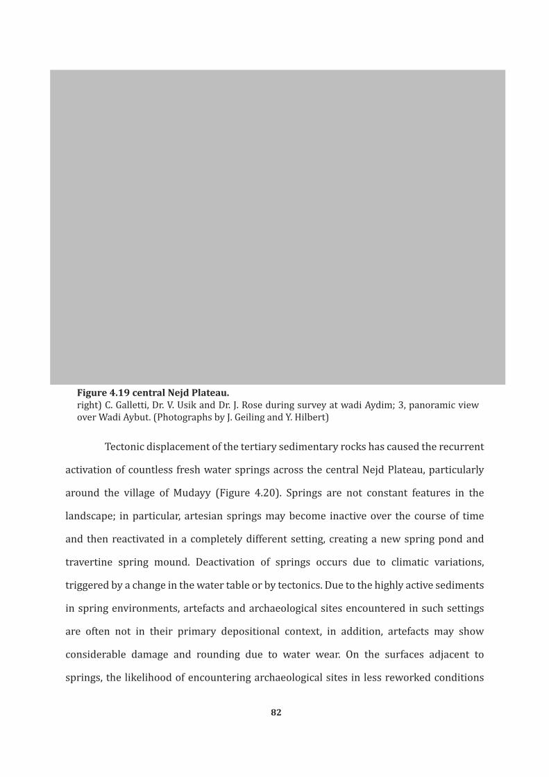
82
Figure 4.19 central Nejd Plateau. right) C. Galletti, Dr. V. Usik and Dr. J. Rose during survey at wadi Aydim; 3, panoramic view over Wadi Aybut. (Photographs by J. Geiling and Y. Hilbert)
Tectonic displacement of the tertiary sedimentary rocks has caused the recurrent
activation of countless fresh water springs across the central Nejd Plateau, particularly
around the village of Mudayy (Figure 4.20). Springs are not constant features in the
landscape; in particular, artesian springs may become inactive over the course of time
and then reactivated in a completely different setting, creating a new spring pond and
travertine spring mound. Deactivation of springs occurs due to climatic variations,
triggered by a change in the water table or by tectonics. Due to the highly active sediments
in spring environments, artefacts and archaeological sites encountered in such settings
are often not in their primary depositional context, in addition, artefacts may show
considerable damage and rounding due to water wear. On the surfaces adjacent to
springs, the likelihood of encountering archaeological sites in less reworked conditions

83
increases. The majority of springs identified by the DAP across the Nejd were categorized
as gravitational springs, which are highly dependent on the ground water levels that per
se is considerably susceptible to climatic oscillation. The use of modern day boreholes and
pumps has considerably lowered the inland ground water level (Johnson, 1998; Beineke,
2006) causing springs across the Nejd to dry out.
Figure 4.20 Springs by Mudayy. both remnant of springs and active springs like the one shown above. (Photograph by Y. Hilbert and J. Geiling).

84
Rockshelters and vertical sinkhole features found across the central Nejd are
unlike those found across the southern Nejd. This is mostly due to the diverging lithology
observed across these two regions, while in the south the Rus formation predominates the
central Nejd is marked by the presence of the Umm er Radhuma formation. Rockshelters
in the central area are close to the main wadi systems across the central Nejd; being of
considerably greater dimensions and commonly presenting native sediments allocated in
front of the shelter situation.
To the east and west of Thumrayt a flat alluvial gravel plain partially covered by
eolian sediments marks the area. The occasional inselberg and other remnants of the
Lower or Upper Hadhramaut Formations may be spotted across the plain. This plain is
dissected by numerous flat erosional gullies and ephemeral streams that carve one meter
deep longitudinal trenches across these flood plains. These gullies do not from large wadi
systems as seen on either side of the gravel plain surrounding Thumrayt.
Past the central Nejd the plateau dips northward and gives way to a gently
undulating plain. The northern Nejd is a flat and homogenous plain that borders the Rub
al Khali desert. On the north western side of the northern Nejd the wadi Aydim flows
through the low gravel hills while to the north wadis Ghadun, Banut, Amut and Aybut
conjoin into the al Burj al Sallyah that also empties into the Rub al Khali. Flat gravel plains
covered with reworked fluvial sands and recent to sub-recent and even ancient alluvial
fans give the northern Nejd some variability. Additional travertine deposits of diverse age
and calcareous paleosols intermingle with Miocene limestone lacustrine deposits are also
attested across the northern Nejd. Based on remote sensing images, Zarins (2001, 24)
proposes that a minor folding event occurred in the Late Pleistocene, which opened up
springs throughout this region. The area around Shisr was particularly affected by this
event, which was responsible for the diversion of stream flow in some of the wadis in the
area (Figure 4.21).

85
Figure 4.21 Northern Nejd and Rub al Khali desert.(Photographs by Y. Hilbert)

86
Further to the north, past the Nejd, the vast Rub al Khali desert stretches over
most of the central Arabian Peninsula. Barchan sand dunes reaching over 200 meters in
height seem to sail across the gravel plains. Late Pleistocene wadi systems running toward
the Arabian Gulf and interdunal fossil lake deposits have been attested throughout the
central Arabian Desert (e.g. Holms, 1960; McClure, 1976, 1978). Alluvial fan remnants
have been found within the Rub al Khali portion surveyed by the DAP demonstrating the
continuation of the Nejd riparian systems into the desert.
4.3 Summary
In this chapter a description of the geology and geomorphological settings
encountered by the DAP team during the field campaigns across Dhofar was given. A brief
description of the Sultanate of Oman was also provided, giving the reader a sense of the
myriad ecosystems and niches found across this part of southern Arabia. Emphasis has
been placed on the description of the lithology, geomorphology and ecology of the Nejd
plateau. Based on Zarin’s partitioning of the Dhofar region into four zones, the coast, the
escarpment, the Nejd and the Rub al Khali desert, further segregation of the Nejd Plateau
into southern, central and northern areas was proposed. These areas have been described
and the relevant geological formations, namely the chert bearing layers that served the
local prehistoric populations as raw material sources for the manufacture of stone tools,
outlined. The three chert types, Mudayy, Aybut and Gahit described as to their appearance
and knapping properties.
The fact that no Late Palaeolithic sites have been found across the Dhofar
escarpment and the costal plain is likely due to the low archaeological visibility and poor
accessibility of the divers landscapes within these environments. Alternatively, it may
be argued that enough moisture reached the southern Nejd enabling Late Paleolithic
populations to remain in this region. The three transects have been chosen for analysis,
ALPHA, BRAVO and GULF are located within the southern and central territories of the

87
Nejd. These have produced in situ assemblages and surface samples located on stable and
deflated surfaces. The following chapter will present the theoretical and methodological
background for the lithic analysis undertaken on the samples retrieved from the Nejd
Plateau.

88
Chapter 5
TOWARDS UNDERSTANDING LITHICS: THEORY AND METHOD
The activities of living creatures, not just the anatomical structures which facilitate their activities, are vital factors in the struggle for existence. Since the time when culture first began to develop, it has influenced the activities of our ancestors. Culture is not only our creation but our creator. −Frederick S. Hulse, The Human Species (1971, 489)
As Hulse observed in “The Human species” (1971) culture and its expressions
have enabled our survival across climatic oscillations, natural catastrophes and culturally
induced calamities (e.g. wars, epidemic outbreaks etc.). Any attempt to archaeologically
grasp a given cultural entity is therefore limited to the analysis of its products and by-
products. As has been noted throughout chapters Three and Four, archaeologists working
in Southern Arabia are forced to focus on the most resilient of cultural expressions; lithics.
Any deliberate technological process is part of the cultural system of a population
and therefore part of a collective cognitive repertoire (e.g. Jelinek, 1976; Sackett,
1982;Davidson & Nobel, 1993; Ingold, 1993). Through cultural transmission technological
processes are passed on through generations, making this most basic aspect of stone
tool technology more resilient to change (Tixier, 1984; Hahn & Owen, 1985; Bar-Yosef
& Meignen, 1992; Monigal, 2002). In order to best categorize and define the samples
pertaining to the Nejd Leptolithic technocomplex, lithic analysis was undertaken. The
analysis of the diverse Late Palaeolithic stone tools found across Dhofar should ultimately
lead to the identification of a local industry. Once its defined comparisons between
the Late Palaeolithic of Dhofar and industries found in adjacent regions may be made.
Such comparisons relay on technological processes used to produce stone tools and the
morphology and taxonomic variability of these stone tools.
Among the goals of this dissertation are the categorization of these technical

89
processes and the placement of these cultural traits into a regional and chronological
framework. This technological framework is accompanied by a specific set of formal and
informal tools, which once recognized can be used as markers of a specific industry.
This chapter will focus on the clarification of the taxonomic nomenclature
and definitions used throughout the analysis. The methodology used to identify the
aforementioned reduction modalities will be explained and exemplified. Stone tools
typology, used to define the Nejd Leptolithic tradition tool kit will be elucidated.
5.1 Reconstruction of reduction sequences
The products of a deliberate knapping event may be divided into cores and blanks,
the earlier being the source of the later. During the production process, the objective piece,
in this theoretical case a flint nodule, is hit in a controlled manner in order to create a
blank, the detached piece (Inizan et al., 1992; Whittaker, 1994; Kooyman, 2000; Andrefsky,
2005). It is important to keep in mind that the core and blank concept is by no means a
static construct; any blank may serve as a source for further blanks, thus being assigned a
core status (Inizan et al., 1992; Hahn, 1993; Usik, 2004).
Further complicating matters, intentionality plays a considerable roll in lithic
technology. By using core reconstructions, diverse phases within knapping events may be
differentiated (e.g. Volkman, 1983; 1989; Demidenko & Usik, 2003). The analysis of core
reconstructions and products of knapping events are here used to recreate the reduction
sequence used by the Late Palaeolithic populations of Dhofar. Refittings and conjoins
will play a major role in the reconstruction of the reduction sequences used across the
aforementioned period.
The term reduction sequence used above is to a certain degree akin to the
chaîne opératoire concept that will be explained later on. Of interest for this study is the
intentional production of standardized blanks anchored within a culturally set array of
reduction modalities. The use of a given reduction modality over another is related to

90
intentionality and choice, making the reconstruction of these modalities a useful marker
for identifying culturally specific traits within the Nejd Leptolithic technocomplex and any
other given cultural unit.
5.1.1 Refittings
The act of piecing together diverse flakes, blades, cores and tools is termed
refitting. This method has been applied to archaeological samples for over a century and
is not restricted to the study of lithic assemblages (Leroi-Gourhan & Brézillon, 1966;
Hofman, 1992). Refitting studies shed light on site formation processes, taphonomic
processes, and organization of living space, raw material economy and the reconstruction
of technological processes (e.g. Bosinski & Hahn, 1972; Cahen, 1976; Hiatala, 1983; Usik,
1989; Adler & Conard, 1997).
The reconstruction of cores using the refitting method not only enables the
identification of specific stages within a technological continuum (Volkman, 1983, 1989;
Bleed, 2002a; Schimelmitz et al., 2011; Hilbert et al. 2012), it also provides verification for
more general lithic analysis (Monigal, 2002). Additionally, this technological component
coupled with spatial analysis provides insights into raw material economy and site function.
Drawbacks of this method are1 the inability to grasp short discontinuous knapping events
undertaken on a given core, and the difficulties of using refittings in an empirical way.
The use of refitting analysis in Arabia is rare, aside from a few exceptions (Rose,
2006; Rose et al., 2011a; Usik et al., 2012; Hilbert et al., 2012; Delagnes et al., 2012).
Possible reasons for this are the dearth of well sampled sites coupled with the overall lack
of technologically oriented studies. This scenario is likely to change given the growing
interest in the area.
Three types of refit-producing sites have been identified and sampled: immediate,
surface and buried (Figure 5.1). Immediate sites are spatially delimited small-scale scatters 1 Not to mention that the process of refitting may at times be painstaking, frustrating, time consuming, frustrating, time consuming and requires considerable amount of lab space; nonetheless, all these troubles are forgotten in the very same moment when artifacts start to fit on to one another.

91
pertaining to a single knapping event. Such sites have shown great potential for refittings
and, as will be seen in following data chapters, often yield complete core reconstructions.
These isolated scatters present the possibility of identifying desired products. Artefacts
removed from the sites have obviously been transported away from the workshops for
further processing.
Figure 5.1 Diverse situations in the field susceptible to production refits.1, photograph of Ghazal Level 2 surface and artefacts; 2, isolated knapping event near Wadi Haluf; 3, large surface site at Wadi Haluf. (Photographs by Dr. Rose and Y. Hilbert)

92
The majority of the surface sites identified by the DAP across Dhofar are extensive
workshop scatters located adjacent to raw material sources. Given the wealth of artefacts
observed on such scatters, selective sampling of smaller unites within such sites was
undertaken. In these cases, refittings help establish the zonation of artefacts within
these immense scatters. Refitting studies were also applied on samples excavated form
buried sites. In these cases refitting studies helped establish stratigraphic integrity and
technological diachronic change (Marks, 1983b).
The methodology applied followed the suggestions made by Demidenko and Usik
(2003). Artefacts have been organized according to category, square units, raw material
and dorsal cortex cover. Three reconstruction types have been identified: conjoins, phase
refits and major core reconstructions. The term conjoin is used to address fragments
from a single blank or core that have been refitted into a complete object. Phase refits are
composed of a series of artefacts refitted to a constellation representing a specific phase
within a continuous reduction sequence. Major core reconstructions are refits that depict
a complete reduction sequence encompassing decortication, core preparation and blank
production.
Based on these criteria, core reconstructions, conjoins and phase refits were
either illustrated or photographed, and described as to the method of reduction used. In
the case of illustrations, the blanks are numbered according to the succession of reduction,
commencing with the first attached piece and ending with the last. These are illustrated in
separate phases in order to make the reconstruction of the cores comprehensible (Figure
5.2). Aside from the identification of reduction modality used, variations within the diverse
methods are described. Based on these observations and the results of the lithic analysis,
reduction patterns can be established. These are used to draw intra site comparisons,
helping to establish the range of technological plasticity within the Late Palaeolithic of
Dhofar.

93
Figure 5.2 Example of illustrated refit from SJ. 51.(Illustration by Y. Hilbert).
5.1.2 Replication studies in lithic technology
The technologies and procedures involved in the production of a stone tool are
myriad. Reconstruction of these work steps may be achieved through replications done by
modern day flintknappers or by drawing analogies from ethnographic contexts. Given that
modern day populations that still depend on and use lithic technology have become rare,

94
replications experiments offer a fair alternative to the reconstruction of past technological
dynamics. Either way, by analysing projectile technology use by Bushmen or replications
done by experienced contemporary flintknappers, information gathered on variability,
and the lack of it, are extremely valuable.
Three distinct approaches to understanding lithic technology through replications
are given: laboratory experiments, modern flintknappers and fracture mechanics theory
(Kooyman, 2000). Laboratory experiments are used to isolate particular elements within
lithic technology (e.g. Dibble & Whittaker, 1981; de Wilde & De Bie, 2011;Dibble & Rezek,
2009; Rezek et al., 2011). These controlled experiments are used to assess variability
within this one isolated feature. This category also includes experiments conduced outside
of laboratory conditions that assess specific questions; for example impact fractures
on projectile points shot at dead animals (e.g Odell & Cowan, 1986), striation patterns
on ground stone tools (e.g Adams, 2002; Dubreuil, 2004) or blade pressure flaking (e.g.
Pelegrin, 2006). Moreover modern day replications of lithic technological procedures help
develop possible trajectories used to achieve one specific goal.
In general replications provide important insights into stone tool manufacturing
processes. Given the myriad variables these replications are subjected to, result should
be viewed as theoretical constructs. These theoretical constructs can then be used to
explain the pattern we seen on the archaeological material, offering insightful information
regarding flintknapping dynamics.
5.1.3 Chaîne opératoire
The chaîne opératoire is a technological approach that aims at the reconstruction
of the technical procedures used by prehistoric populations. In other words, through it the
archaeologists seek to elucidate the succession of mental operations and technical gestures
used by cultural actors to accomplish a given task (Perlès, 1987; Sellet, 1993; Shott, 2003).
Consequently, this analytical principle aims at the description of the transformations

95
processes applied to a given raw material starting with its acquisition and ending with the
abandonment of the exhausted tool (Binford, 1977, 1979; Tixier et al. 1980). Through it
a chronological segmentation within this aforementioned continuum is achieved. Each of
these chronologically divided phases encompasses distinct mental processes required to
accomplish all stages of tool manufacture and maintenance.
Through the reconstruction of the raw material procurement systems exerted
by past populations, statements concerning basic constraints on stone tool technology
may be made. The availability of high, or low, quality raw material at a given site has
been known to affect the organization of technology; namely the production of formal vs.
informal tools (e.g Inizan et al., 1992; Andrefsky, 1994). Raw material size constrains the
dimensions of the artefacts found at a given site, making the localization and description of
the raw material outcrops central when dealing with stone tool size variability. In regards
to organization of blank production systems and the configuration of site assemblages,
site distance to source may bring forth diverging solutions to raw material curation prior
to transport. In other words rocks are heavy and to carry them around costs energy. Early
stage maintenance, as in decortication of nodules and core preparations, is more intense
at the quarry sites if the distance to the living site is greater (e.g Newman, 1994; Beck et
al., 2002). If the raw material source is close to the site, entire nodules will be transported
and reduced directly at the site. In general the analysis of raw material economics should
serve to determine the type of raw material, its quality and how it got to the site (Ericson,
1984; Sellet, 1993).
The analysis of lithic production, based on refittings, perusal of cores and metrical/
morphological analysis of the blanks are undertaken in order to establish pattern of lithic
reduction. Within the chaîne opératoire analysis of the blanks, each piece is appointed
a specific place within the reduction. The objective of this step is to identify the goal or
preferential end products of a deliberate blank producing system (e.g Van Peer, 1992;
Boëda, 1994; 1995; Usik, 2006). The categorization of lithic production technology into

96
stages is based on what is done within each of these stages, thus blanks will bear features
that may be associated with one of these phases (Kooyman, 2000; Bar-Yosef & Van Peer,
2009).
Once a blank is modified by retouch it is here considered a tool. The study of
tool use, maintenance and discard complete the scope of the chaîne opératoire approche.
The goal of this phase is not the reconstruction of the tools function (this aspect is better
enlightened by use wear and trace analysis), but rather to refine the data provided by
the typological analysis. By analysing the processes that created the tool, thus applying
a technological perspective, better taxonomic control over tool variability may be made.
5.2 Débitage Analysis
Any archaeologist that has worked or enjoys the fortune to be working with a lithic
assemblage will confirm that the amount of work invested in sorting through countless
bags of flakes, blades, chips, bladelets and other blanks is enormous. The amount of
information gathered is immense, raising the question of what to do with all this data and
most importantly what does it mean? Entire volumes and countless articles have been
dedicated to inferring meaning and order onto débitage (e.g Dibble & Whittaker, 1981;
Sullivan, A. & Rozen, C. 1985; Ahler, 1989; Shelley, 1990; Bradbury & Carr, 1995; 1999;
Ballin, 2000; Andrefsky, 2001).
The term débitage is derived from the French school of lithic analysis (e.g. Bordes,
1961; Inizan et al., 1992; Boëda, 1994) and stands for all products a deliberate knapping
event, including cores. A narrower definition of this term is used here, synonymous with
the term blank. Following Munday (1976) and Fish (1976) débitage encompasses all
product and by-products of any deliberate knapping event (either blank production or
tool manufacture) excluding only cores and tools.
Within the Anglophone school of lithic technology blanks have also been viewed
as products of deliberate knapping events; these desired products were chosen for further

97
modification into tool (Bradley, 1975; Sullivan & Rozen, 1985). The waste of a deliberate
knapping event, primary, secondary and tertiary flakes (cortical elements) were not
considered to be blanks. Based on the chaîne opératoire approach it has been shown that
cortical elements, regardless of the amount of cortex they posses, have some potential of
becoming a blank for tool manufacture (David, 1993; Roth et al., 1998; Stout, 2002). Thus
the segmentation of knapping products into blanks and waste will not be used throughout
this study.
Using theoretical constructs, experimental replications and refits, researchers
infer meaning and order upon débitage. Based on these, some basic assumptions may be
made: débitage are volumes of raw material produced from other volumes by percussion
or pressure. These can be further divided into sub categories based on metrical
proportions (flakes, blades, bladelets and chips) and the amount of cortex on their dorsal
surface (cortical pieces). Other objects may be identified as part of specific technological
reduction modalities (bifacial thinning flakes, débordant elements, crested blades, Levallois
preferential products etc.). These classificatory terms are used to infer when within the
chaîne opératoire the artefact was produced. Débitage showing a considerable cortical
dorsal percentage are held to be part of the early decortication stage, but identifying the
transitions between each stage is difficult. Artefacts produced at the end of a reduction
stage and artefacts produced in the initial phase of the subsequent stage will share very
similar morphologies, making classification problematic. The categorization of these
theoretical stages of reduction is a useful analytical tool, but it has to be kept in mind
that core reduction is a continuous process subject to many variables (e.g. Marks, 1983b;
Boëda, 1994; Whittaker, 1994; Bradbury & Carr, 1999; Tostevin, 2007; Bar-Yosef & Van
Peer, 2009; Van Peer et al., 2010).
The taxonomic attribution of débitage alone is of little use considering the static
characterization of débitage typology. By analysing set features observed on blanks and
the interplay between these features the technological processes that generated the

98
débitage may be laid bare making such analysis valid (Hahn, 1993). The identification of
purpose within the débitage production system is one of the central dilemmas within lithic
analysis. Whether a flake was produced using a blade reduction system or the shaping of
a bifacial tool may be answered based on the analysis of separate lines of evidence (Hahn,
1993; Odell, 2004; Andrefsky; 2005; 2009). Identifying intentionality implies looking
into the mind of the maker. Through refitting studies, variability within technological
processes and behavioural aspects of raw material economy may be inferred (Demidenko
& Usik, 2003), thus allowing for the reconstruction of the processes that produced the
object in the first place. On the other hand, over-formalization and the lack of an empirical
basis in technological studies have clouded our ability to explaining patterns identified by
the chaîne opératoire approach (Bar-Yosef & Van Peer, 2009). So why go through all the
trouble? If typology is not the answer and the tools used by prehistorians to reconstruct
past processes are not entirely based on empirical data how do we proceed? Technological
reconstruction of past processes can provide vivid insights into activities undertaken by
past population, thus making it feasible to sort through tons of débitage. The principle
limitation of archaeology lays in our incapability of fully reconstructing the cultural
systems that created the artefacts we study.
Keeping these thoughts in mind this study addresses the classification and
definition of material culture pertaining to Late Palaeolithic of Dhofar. Neglecting the
débitage would be like cooking without a fire; it can be done but the result will not
satisfy every palate2. By looking at scar patterns, striking platform morphology, vertical
and horizontal cross-section, blank terminations and metrical parameters a profile for
each artefact is created. Thanks to core reconstruction and replication experiments the
parameters responsible for the configuration of the established blank profile may be
inferred.
2 Like Japanese food (sushi) for example.

99
5.2.1 Blank orientation and measurements
Blank dimensions are sensitive to a series of factors, mostly related to raw
material dimensions and knapping qualities, and reduction modalities used (Dibble &
Whittaker, 1981; Newman, 1994; Shott, 1994; Kooyman, 2000; Dibble & Rezek, 2009).
At illustrations and during analysis débitage are oriented with their striking platforms
pointing down and the terminal portion pointing away from the viewer. Blank length,
width, thickness, weight, platform width, platform thickness and platform angle were
measured for this study (Figure 5.3). The three main measurements taken directly on the
artefacts, length, width and thickness, reflect the blanks approximate volume. Blank and
blank striking platform dimensions were taken using an electronic calliper, with an output
directly into the database used (given in millimetres: mm). Blank length was determined
starting from the striking platform to the furthest point following the blanks’ technological
axis. Blank widths were taken at the central portion of the artefacts oriented horizontally
to the technological axis and blank thickness was determined perpendicular to where the
artefacts’ widths were determined.
Figure 5.3 Blank orientation and measurements. As noted in the text, artefacts are oriented with their striking platforms down, except when incorporated into refittings. In these cases, for clarity sake artefacts are depicted with the striking platforms pointing up, matching the illustrated core and reduction orientation. (Image by Y. Hilbert)

100
Striking platform dimensions were taken (width and thickness) following the
method applied to determine overall blank dimensions. Platform width was measured
as the distance between the edges of the plane following blank midpoint width. Platform
thickness was determined as the distance between the point of percussion and the
intersection of the striking platform and the dorsal surface of the blank. Platform size,
width and thickness, were found to have great influence on overall blank volume (e.g
Dibble, 1997; Kooyman, 2000)
In order to determine the metrical variability among the débitage for a given
assemblage, indices have been calculated based on the above described metrical
parameters. Average values (arithmetical mean) and standard deviation (calculated on the
basis that the samples dealt with are but a part of the population rather that representing
the complete population) are used to represent both variability and lack thereof within
the analysed assemblages. Index of platform flattening (IPF), is found by dividing platform
width by platform thickness. Values around 2 indicated that the blank is rectangular in
shape and twice as wide as it is thick. Values approaching 1 indicate that the platform is
square. The higher the values the thinner and wider the platform is. The index of blank
relative platform size (RPS), estimated by dividing the blanks area (lengths multiplied by
width) by its platform area (platform width multiplied by platform thickness), has bee
estimated for all complete blanks within each of the samples. This index indicates the
relative size of the platform in respect to the blanks size. The higher this value the smaller
the blank’s platform is in regard to the blank’s size. Index of elongation was equally
determined to grasp the extent of general elongation; this value is determined by dividing
the blank’s length by its width. By definition, blades and bladelets will have values equal
or above an index value of 2. The higher the value the longer the blank, and if the value of
a blank is lower than 1, the piece is wider than it is long.

101
5.2.2 Blank Type
Although little information per se is given by this taxonomic attribution, the
percentage of specific types of débitage within a given assemblage (blades, bladelets
and débordants) may represent a useful indicator for identifying specific production
modalities. Furthermore these rough markers may be used for drawing comparisons
between assemblages on a lower analytical scale.
5.2.2.1 Flake
The word flake refers to any piece of débitage detached from a core or tool. No
specific morphology, use or dimensions are inferred by this terminology. If a flake was
smaller that a thumbnail (10 mm in maximum diameter) it was termed a chip. Flakes have
been further segregated into cortical, débordant or bifacial thinning flakes depending
on morphological characteristics. Cortical flakes have more than half their dorsal side
covered by cortex (over 50%). If the flake was detached from the lateral portion of the
core, removing either a former lateral striking platform or simply having a cortical back
the termed débordant flake is used. These are mostly lateral and steep in horizontal cross-
section, and reduced off-axis in relation to the dorsal scar pattern.
Bifacial thinning flakes (BTF) are produced as a result of a façonnage oriented
reduction of specific tool forms, mostly bifacial implements. The façonnage reduction
method aspires to shape a desired tool form by means of progressive retouch of a given
block of raw material (Inizan et al 1992; Hahn, 1993; Debénath & Dibble, 1994). BTF´s are
identified based on metrical parameters and morphological characteristics. These present
an intensely faceted striking platform and are curved to twisted in their horizontal cross-
section.
5.2.2.2 Blade.
The term blade is used here in a strict Bordian sense of a given flake that is at

102
least twice as long as it is wide (Bordes, 1961). Interpretative segregations between “true
blades” (Bordes & Crabtree, 1969) and “flake-blades” (e.g. Singer & Wymer, 1982) have
been discussed elsewhere (Monigal, 2002), and are not considered further here. The
purely metrical definition serves the purpose of this study just fine.
Within this cadre of elongated débitage the following variations were found
relevant and have been differentiated: cortical blades, débordant blades and bladelets.
Having more than half their dorsal surface covered by cortex marks cortical blades.
Débordant blades are débitage elements reduced from the lateral edges of a core’s working
surface that are at least twice as long as they are wide. Commonly, débordant blades are
struck off-axis and present a lateral steep medial cross-section. The lateral portion of
these artefacts is cortical, and given their appearance these artefacts have been named
“naturally backed knifes” (NBK) (Shimelmitz et al., 2011). Attribution of débordant blades
as NBK is regarded as inappropriate for the samples form Dhofar given that no signs of
use, or retouch have been observed on any of the débordant elements analysed for this
study. Moreover, the technological aspect of these removals, in many cases with overshot
terminations, appears to be related to horizontal and vertical convexity creation and
maintenances (e.g Meignen, 1995; Hays & Lucas, 2001; Le Brun-Ricalens, 2005;).
Bladelets are diminutive blades, created by diverse reduction strategies (e.g.
Owen, 1988; Blades, 2001; 2005; Kuhn, 2002; Bleed, 2002b; Le Brun-Ricalens, 2005;
Taller & Floss, 2011). The definition adopted here is a pure metrical one and follows Tixier
(1963), which states that elongated, twice as long as broad artefacts not wider than 12
mm are regarded as bladelets.
5.2.2.3 Technologically diagnostic débitage.
This term assembles the remaining débitage that are found to be characteristic of
specific technological processes and therefore associated with specific types of stone tools
and reduction modalities. These are: crested blades, core tablets and burin spalls.

103
Crested blades are associated with true volumetric blade technology as described
for diverse Palaeolithic assemblages in the old world (see Demidenko & Usik, 1993b). The
purpose of this particular step in blade production is the creation of a triangular central
guiding ridge on a core’s working surface. This is achieved by transverse bifacial removals
along the narrow edge of a raw material nodule; once direct percussion removes the
guiding ridge, recurrent blade reduction on this face takes place.
Core tablets are part of blade production sequences, these are flakes struck
perpendicular to the core’s working surface, serving the purpose of renewing faulty and/
or exhausted striking platforms.
Burin spalls are by-products of burin production. These tools are characterized
by the removal of narrow, bladelet-dimensioned blank from the edges of a flake, blade or
any other given débitage. Burin spalls are triangular or trapezoidal in cross-section and
present dorsal scars that are perpendicular or highly oblique to the plane of the blank
itself (Marks, 1976; Inizan et al., 1992).
5.2.3 Blank Condition
Blanks were found either in complete, proximal, medial or distal states.
Occasionally false burin fractures were observed. Only complete débitage were fully
measured, blanks that were missing a small part of their proximal or distal portions have
been regarded as incomplete. These pieces have been measured as well, given that such
small fractures would have had little influence on the overall dimensions of the blank.
Proximal, medial and distal fragments have been partially measured; only width and
thickness were taken. False burin blows, also termed siret fractures (Inizan et al., 1992)
occur when the force created by the hammerstone hits the striking platform and travels
unexpectedly along raw material faults, causing the blank to splitter into two pieces on a
vertical axis. The term used by Anglophone researchers hints at the similarities between
this rupture and the purposefully administered burin blow.
104
Further notes on the condition of débitage found at a site include whether
artefacts have been burned, indicating the use of fire at the site. It has been observed
that some artefacts from surface scatters were covered with podlits fractures. These are
naturally occurring fractures induced by temperature oscillations; small circular flakes
are detached from a parent block. In cases observed across Dhofar, fracture was so intense
that only rough scar patterns could be identified on the affected débitage.
5.2.4 Patina
Patination is a process that affects all kinds of archaeological vestiges (Rottländer,
1975; Schiffer, 1983); it forms on the surface of artefacts and is triggered by chemical
processes. Patination occurs when artefacts are logged within stable sediments or resting
on stable surfaces. In lithic studies the term patination has been used to describe a series
of macro-chemical and physical effects on stone tools. Experiments and formation-process
oriented studies have shown that several specific elements related to environmental,
mineralogical and anthropic factors have considerable effect on surface modification
(Goodwin, 1960; Ackerman, 1964; Rottländer, 1975; 1978; Purdy & Clark, 1979; 1987).
Studies of both surface and buried materials are dependent on the quality and
integrity of the archaeological finds (Hodder & Hutson, 2003). Artefact patination may be
used as an indicator that pieces resting on stable surfaces have gone through similar post-
depositional trajectories (Hunt, 1954). That is to say are likely to be coeval. Patination
processes are related to a series of factors as was stated above, crucial to its formation and
further development is the matrix in that the artefacts are bedded or have been bedded
in (Schiffer, 1983). During the DAP field campaigns it has been repeatedly observed that
at prominent raw material outcrops clusters of diversely patinated artefact presented
diverging technological reduction strategies. Especially at Umm Mudayy, this pattern has
been found accompanied by a special element related to the general landscape evolution
prevailing across the Nejd. The site is marked by a limestone remnant that continuously

105
suffered erosion across the Late Pleistocene. As further back this limestone remnant
eroded, high quality Mudayy chert become exposed, which has then been exploited by
diverse human groups across time. It may be inferred from this evidence that, while
patination cannot be used as proof of antiquity, the identification of diverse patterns on
surface scatters may possibly indicate a certain time depth between the creations of the
diversely patinated objects and the availability of raw material at their primary sources.
Advances in microscopy have revealed the additional potential in patination
studies (Burroni et al., 2002; Fernandes et al., 2007). By using data from knapping
experiments and naturally occurring flint comparative examples have been gathered. It
is clear that the abovementioned factors had a greater effect on patination of lithics than
time has.
Give the above mentioned specifics the patination observed at each of the analysed
sites were dealt individually. Among both surface and buried sites the repeated occurrence
of artefacts presenting two patination phases were observed. This phenomenon relates to
the re-utilization of flint artefacts that have been lying on the surface and were collected
intentionally for further modifications. At the Jebel Eva (TH.67) site, described in full later,
artefacts presenting two distinct patination patterns have been refitted to one another.
The artefacts were collected from restricted areas and yet have shown great variability
in patination, the refits and technological analysis revealed they belong to the same
technological tradition. Further occurrences similar to the one described above have
been mentioned for other sites in Southern Arabian (Crassard, 2008a). The cause of this
phenomenon may be seen in the possible effect of past climatic oscillation in the area
and the impact of these oscillations on vegetation dynamics. A possible scenario for the
development of such patination discrepancies may be related to punctuate vegetation
occurrences; these would have increased soil moisture. This increase in moisture would
have had local effects on artefacts in a small range leaving artefacts located further away
unaffected. Post-depositional deflation and site disarticulation would then shape the sites

106
into their present condition.
5.2.5 Edge damage
Of interest to the reconstruction of the post-depositional trajectory of surface
and buried assemblages is the influence of physical force on the artefacts themselves.
Post-depositional deflation and/or erosion by fluvial and eolian factors are known to
have specific effects on all sorts of archaeological artefacts (Dunnell, 1990; Gregg et al,
1991; Lyman, 1994; McBrearty et al., 1998; Eren et al., 2011). One of the effects of physical
displacement may be read directly on the artefacts’ edges. Hahn summarizes these
appearances as GSM-Retusche (Gebrauchs- Sediments – Museums- Retusche; use, sediment
and museum retouch), and defines these as being edge damages that have no intentional
origin (Hahn, 1993, 167).
For the purpose of estimating how intense post-depositional displacement
influenced both surface and buried assemblages, edge damage analyses on artefacts have
been conducted. Artefacts have been placed into one of four categories depending on how
intense edge damage appeared (Figure 5.4).
No edge damage. Artefacts presenting pristine edges have been placed in this
category, indicating no post-depositional displacement or very gradual and low energy
displacement that left no visible signs on the artefacts edges.
Slight edge damage. Artefacts showing minimal and infrequent damage across
one or more edges have been placed in this category. Small negative scars not following
any pattering across one or more edges, sometimes alternately between ventral and
dorsal surface have been attributed to sedimentary motion and minimal post-depositional
displacement of the artefacts.

107
Moderate edge damage. This rubric characterizes artefacts showing continuous,
unsystematic abrupt to semi-abrupt breakage across one or more edges. Similar to the
damage described above, the alternation of negative directionality between ventral and
dorsal is regarded as typical for so called sediment retouch. The appearance of this damage
pattern is indicative of some degree of displacement suffered by the site and the artefact.
Heavy edge damage. Characterized by intense rounding and abrupt truncation
like damage on the artefacts’ edges. This type of heavy damage is related to intense
redeposition. Not necessarily long distance transport from its original source is implied
here, rather intense as in highly energetic over a short distance.
1 2 3
Figure 5.4 Edge damage on artefacts for archaeological context. 1, blank with no edge damage; 2, slight edge damage; 3, moderate edge damage. (Photograph by Y. Hilbert)
5.2.6 Raw Material
Raw material specifics have been found to be highly site specific and will therefore
be discussed separately for each presented assemblage within the data chapters. The
following general remarks concerning variability, or the lack of it, may be made. The
presence of raw material across the Nejd Plateau is ubiquitous, and both nodules and
plaquettes are of superb knapping quality (Figure 5.5). As it has been pointed out in
chapter Five, the Southern Nejd is marked by two chert bearing members within the Rus
formation. This geological formation is mostly absent from central and northern portions
of the Nejd; there, different chert bearing formations have been identified as noted in

108
chapter Five. Chert outcropping from the Mudayy member has been found in the proximity
of the Jebel Eva site (TH.67) located in the central portion of the Nejd.
Figure 5.5 Raw material nodules in situ at Wadi Haluf . (Photograph by Dr. J. Rose)

109
5.2.7 Platform Morphology
By looking at the striking platform the original core striking platform may be
reconstructed. Additionally specific treatment of each individually detached blank may
be analysed (Dibble, 1997; Monigal, 2002). Information related to the percussion tool
the prehistoric craftsman used to produce the archaeological evidence may be read
from breakage patterns on the blank’s striking platform. The following striking platform
characteristics have been recorded in order to assess blank production variability within
the Nejd Leptolithic: platform type, the presence or absence of lipping and the presence
or absence of abrasion.
5.2.7.1 Débitage platform types
Striking platforms prepared by direct flaking will be visible on the blanks reduced
from the core. These removals, intended to eliminate any irregularities on the striking
platform and enhance blank detachment control are elements of technological action
passed on within a cultural frame and therefore specific to a given lithic industry. Platforms
have been divided into eight categories defined below (Figure 5.6).
Cortex. The striking platform on the blank is either cortical or made up of any
other given naturally weathered surface. No preparation prior to blank removal has been
undertaken, indicating that the core’s striking platform presented a natural suitable angle
for blank production.
Unfaceted. Blank removal was done on a flat core striking platform, prepared by a
single blow; leaving the striking platform of the blank plane and straight.
Punctiform. The striking platform on the blank was heavily reduced by abrasion
and small removals. Punctiform striking platforms are characterized by their diminutive

110
size and show a great deal of percussion control by the prehistoric craftsman.
Dihedral. The blank was struck on or in the proximity of the intersection of two
former removals on the core’s striking platform.
Faceted. The blank striking platform shows three or more removals undertaken by
the precursor in order to enhance blank removal control. Preparation of a faceted striking
platform must take place from the intersection of the core’s plane of removal and the
striking platform. Given the absence of the Levallois method within the Nejd Leptolithic
core reduction spectrum, blanks presenting faceted striking platforms are attributed to
reorganization of removal directionality within core reduction.
Transverse. This type of striking platform, although similar to the above described
dihedral and faceted striking platforms differ from the two later in that removals on the
core’s striking platform were administered transversely to the orientation of the core’s
plane of removal. These transverse striking platforms occur due to the rearrangement of
the directionality of blank reduction, and are not considered part of intentional striking
platform preparation.
Crushed. The removing blow was undertaken too close to the core striking platform
edge thus damaging the striking platform on the blank. Crushed striking platforms could
not be measured, however, considering the limited effect to the blank overall dimensions,
artefacts with this particular damage have been considered complete.
Absent/ unidentifiable. This category was applied when the striking platform
has been found missing due to breakage or attribution to any of the above mentioned
categories has failed.

111
5.2.7.2 Lipping
The term lip refers to a slightly projecting overhang at the interface between the
blanks striking platform and its ventral surface (Bordes, 1961; Marks 1976; Inizan et al.
1992). The presence or absence of this particular aspect of striking platform morphology
has been attributed to the usage of a soft percussion instrument vs. the hard hammer
technique (Inizan et al. 1992; Hahn, 1993). Hard hammer percussion is associated with
the formation of a herzian cone and a prominent bulb of percussion, which involves
immediate fracture directly at the striking point. Soft hammer percussion, however, is
associated with bending fracture mechanisms that cause the fracturing and subsequent
detachment of the blank to occur at some distance from the point of percussion (Kerkhof
& Müller-Beck, 1969). While diverse features are related to the formation of such a
bending fractures (Crabtree, 1970; Whittaker, 1994; Kooyman, 2000), mostly related to
raw material properties and platform angles, both hard and soft fabricators may cause the
formation of a lip.
For the purpose of identifying variability among percussion tools used by Late
Figure 5.6 Blank platform types. 1, cortical;2, straight; 3, punctiform; 4, dihedral; 5, faceted; 6, transverse. (Image by Y. Hilbert).

112
Palaeolithic flintknappers of Dhofar a distinction between lipped, “semi-lipped” and not
lipped was made. Semi-lipped artefacts present a blend of both aforementioned categories:
(a) a lip, although not as prominent as in the lipped category; (b) a diminished and flat
bulb of percussion.
5.2.7.3 Platform abrasion
The mechanical act of wearing away the intersection between the striking platform
and the blanks’ dorsal surface is termed platform abrasion. This procedure would have
been performed prior to blank removal in order to smooth any overhangs from the cores
striking platform, thus stabilizing it. Given the preparatory character of this act, platform
abrasion will be visible only on the dorsally facing portion of the blanks’ striking platform.
This procedure is held to be conducive to blade production (Crabtree 1970; Inizan et al.,
1992; Delagnes 2000; Monigal, 2002). Given that the Late Palaeolithic is characterised
by blade production, the occurrence of this feature should help establish variability
within the reduction methods used. Four distinctive variations of preparatory platform
treatments have been distinguished: no preparation, partial preparation, preparation and
inverse preparation.
Artefacts presenting platform abrasion covering part of the intersection between
the striking platform and the dorsal surface of the blank have been classified as partially
prepared. The reason for such a partial treatment of the striking platform may have had two
possible causes; (a) platform abrasion was administered once for every reduction cycle,
thus only a few blanks with completely abraded platforms would have been produced
leaving the subsequent blanks with either partially or unprepared striking platforms; (b)
selective abrasion intended to reduce only disturbing factors on the core striking platform
resulted in a partial abraded pattern.
Additional variability within this particular platform treatment is related to
the disposition of the striking platform itself. Some cores have received more attention

113
than others, meaning that specific technical curation measures, such as striking platform
renewal, were not undertaken on all cores. In those cases where renewal has been
undertaken, additional inverse platform edge grinding has been observed. This means that
instead of moving the hammerstone along the striking platform towards the flaking plane
on the core, directionality followed the inverse motion from the flaking surface towards
the striking platform. The identification of such curation methods helps the identification
of cycles within recurrent, seemingly linear, blank production systems.
5.2.8 Blank Shape
This specific aspect of blank morphology is dictated by an interconnected set
of morphological traits. It is thought that a deliberately prepared core should deliver a
certain number of pre-set shaped blanks (Van Peer, 1992; Demidenko & Usik, 1993a;
Monigal, 2002; Schimelmitz et al., 2011). Major factors determining blank shape are the
technological procedures of core preparation, the core’s striking platform layout and the
preceding removals on the core’s working surface. The latter are of great significance for a
recurrent blank production system given that the arêtes (negative edges) left on the cores
working surface by preceding blank negatives serve as guiding elements for the following
blanks detached.
Given the Leptolithic character of the blank production systems used during the
Late Palaeolithic in Dhofar, overall blank shape of both blades and flakes are highly related
to the technological organization of the core working surfaces used (Hilbert et al., 2012).
Blanks have been divided into eight morphological categories based on the disposition of
their lateral edges (Figure 5.7)
Parallel. The blank is rectangular in shape presenting two parallel sides. Within
a recurrent unidirectional reduction system this particular blank form will be most
common.

114
Expanding. The blank’s width increases toward its distal part. The edges of the
blank expand forming an upside down triangle, resembling a fan.
Convergent. The sides of the blank converge towards the distal portion, creating
a blank with pointed end. The blank is triangular in shape.
Débordant/lateralized. These blanks present one incurved and one linear
or semi-linear edge. For a greater part this blank shape is associated with débordant
elements removed from a lateral edge of the core’s working surface. These removals are
intended to recreate the cores working surface convexity (Meignen, 1995; Barkai et al.,
2005; Shimelmitz et al, 2011; Hilbert et al. 2012).
Ovoid. This blank form is characterized by edges that extend proximally and
converge distally gradually, without angular changes along its silhouette. thus forming a
circular outline.
Curved. These are blanks presenting two parallel converging edges that do not
proceed in a straight line. The blank’s edges stray towards one of its two sides.
Diamond. This shape has been repeatedly observed within the late Nejd
Leptolithic and has been found associated with the Wa’shah reduction method (Crassard
& Bodu, 2004; Crassard, 2008a; 2008b). The diamond shaped blanks are characterized by
a bilateral divergence in the proximal medial portion of the blank, followed by convergent
edges culmination in a point at the distal portion.
Irregular. When the silhouette of the blank does not match any of the above
mentioned classificatory types.

115
5.2.9 Blank midpoint cross-section
This particular feature of blank morphology is related to the core’s working surface
layout and where the removing blow was administered at the core’s striking platform.
These factors influence the metrical morphologies of the blank, which in turn influences
the shape of blanks midpoint cross-section. Especially within a blade reduction system,
where each successfully removed blade creates additional arêtes that serve as guiding
ridges for subsequent blade removals, blank cross-section may give valuable information
regarding the use of such recurrent reduction system. For the purpose of this study eight
distinct cross-section types have been identified (Figure 5.8).
Figure 5.7 Blank Shape. 1, parallel; 2, expanding; 3, converging; 4, lateralized; 5, ovoid; 6, incurvated; 7, diamond shaped; 8, irregular. (Image by Y. Hilbert)

116
Figure 5.8 Blank midpoint cross-section schematics. 1, flat; 2, triangular; 3, lateral steep; 4, trapezoidal; 5, more than three vectors;6, rectangular; 7, pitched; 8, convex. (Image by Y. Hilbert).
Flat. No arêtes are present on dorsal surface, indicating that the dorsal surfaces
was either formed by a single negative on the core’s dorsal surface or a flat natural fracture.
Débitage exhibiting such cross-sections are usually very thin.
Triangular. One central ridge visible is on the blanks dorsal surface and was
caused by two removals on core’s working surface. The position of this central arêtes
varies in respect to its position across the midpoint section of the blank.
Lateral Steep. Also triangular in cross-section, this pattern has been found typical
on débordant elements. Characteristic for this cross-section is the one lateralized ridge
forming a right-angled triangle.
Trapezoidal. Three parallel plains, with two central ridges, form the dorsal surface
of the blank. Trapezoid cross-sections have been observed repeatedly on elongated blanks;
indicating a specific exploitation patterns for these blanks.

117
More than 3 vectors. This cross-section type shares certain aspects with the
previously described trapezoid cross-section. The main difference lies in the greater
amount of parallel to sub parallel planes and ridges, giving the blank a more complex
cross-section.
Rectangular. Similar to trapezoidal this cross-section presents three parallel
plains, yet the two ridges separating these planes are localized on the very edges of the
blank and arranged in a right-angle to each other. Blanks removed from the narrow edge
of a core often display such a cross-section. On some occasions, when a chert plaquette is
used as a core and reduction starts at one of the narrow ends, the produced blanks will
show a rectangular cross-section where the two edges will be cortical.
Pitched. Like the rectangular type this particular type of cross-section presents
two perpendicular sides parallel to each other with the addition of one dihedral plane on
its dorsal surface.
Convex. The blanks presenting this cross-section have no planes associated with
preceding removals. The convex shape is due to the cortical surface.
5.2.10 Blank distal portion
The condition of the blank’s terminal portion describes the distal end of the
detached piece; thus giving information about the cores horizontal convexity. Additionally
the state of the distal termination yields evidence as to the amount of force, how this force
was applied to the core and possible mishaps involving any of the two aforementioned
variables. Experimental data based on fracturing mechanism pinpoint the exterior
flaking angle as being one of the main guiding mechanisms governing blank termination
(Bonnichsen, 1977; Cotterell & Kamminga, 1979). This data refers to the angle formed
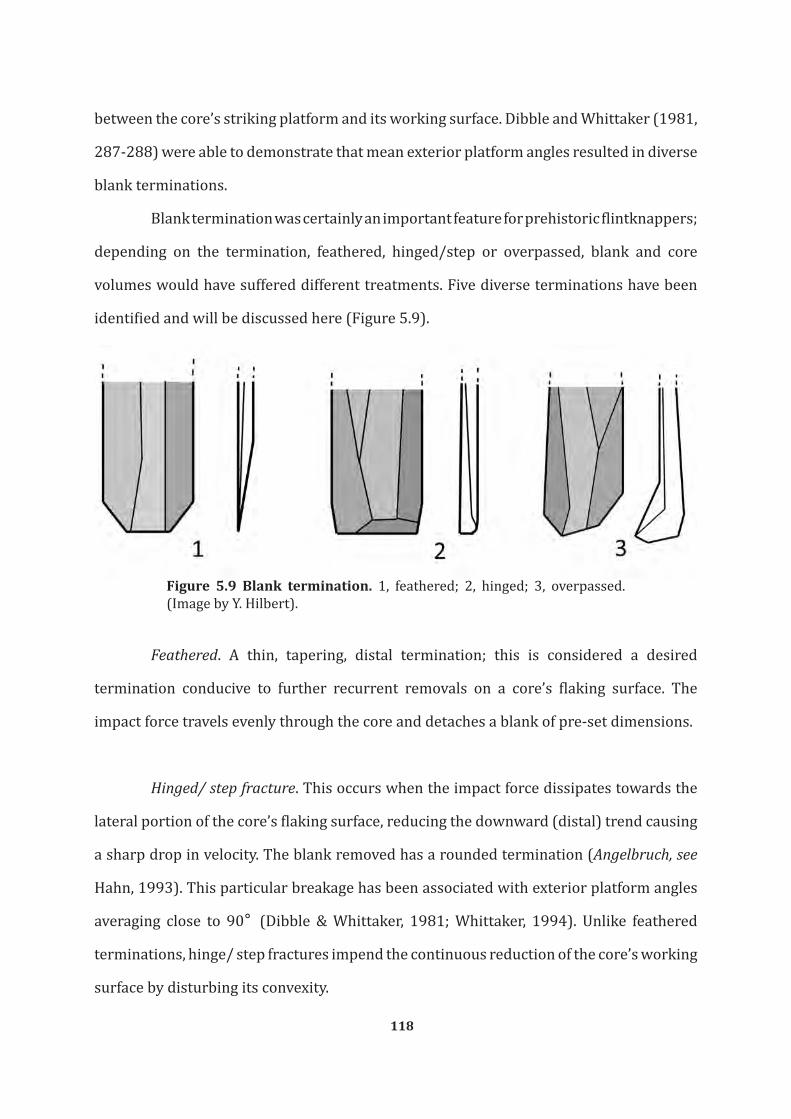
118
between the core’s striking platform and its working surface. Dibble and Whittaker (1981,
287-288) were able to demonstrate that mean exterior platform angles resulted in diverse
blank terminations.
Blank termination was certainly an important feature for prehistoric flintknappers;
depending on the termination, feathered, hinged/step or overpassed, blank and core
volumes would have suffered different treatments. Five diverse terminations have been
identified and will be discussed here (Figure 5.9).
Figure 5.9 Blank termination. 1, feathered; 2, hinged; 3, overpassed. (Image by Y. Hilbert).
Feathered. A thin, tapering, distal termination; this is considered a desired
termination conducive to further recurrent removals on a core’s flaking surface. The
impact force travels evenly through the core and detaches a blank of pre-set dimensions.
Hinged/ step fracture. This occurs when the impact force dissipates towards the
lateral portion of the core’s flaking surface, reducing the downward (distal) trend causing
a sharp drop in velocity. The blank removed has a rounded termination (Angelbruch, see
Hahn, 1993). This particular breakage has been associated with exterior platform angles
averaging close to 90° (Dibble & Whittaker, 1981; Whittaker, 1994). Unlike feathered
terminations, hinge/ step fractures impend the continuous reduction of the core’s working
surface by disturbing its convexity.

119
Overpassed. Whereas hinged fractures occurred when core convexity and impact
force are insufficient, overpassed or overshot terminations occur when the force that was
intended to detach the blank travelled through the core removing its distal portion. Blanks
with overpassed terminations may be purposefully removed in order to create and retain
flaking surface convexity. Additionally, valuable metrical data may be gathered given that
the length of overshot blanks is related to core overall working surface length.
Absent. The distal termination cannot be recorded due to breakage after
detachment from the core. In cases where the distal termination was removed due to
retouch a note was added to the database.
5.2.11 Blank Longitudinal profile
This particular feature of blank morphology describes the silhouette of the
blank when viewed in vertical profile (Andrefsky, 1986). Three diverse stages of blank
longitudinal profile have been observed on the blanks: flat, incurvate and twisted. The
longitudinal layout of the blanks is thought to reflect architectural features on the core’s
working surface and the position from where these blanks have been reduced.
A blank presenting a flat profile is characterized by a plain ventral surface with
no bends or rotations to either side. If the blank presents an arched ventral surface, it
is attributed an incurvate profile. Laterally-curved blanks have been attributed to the
twisted category. These are associated with the removals from peripheral portions of a
core’s working surface.
5.2.12 Axis
This rubric describes whether the technological axis, the axial directionality of the
removals visible on the dorsal surface of the blank, coincides or not with the directionality
observed on the blank’s ventral surface. Whether a blank is on or off-axis has been found
120
to relate to the intentionality of the flintknapper and core platform disposition. Débordant
elements have often been found struck off-axis (Monigal, 2002). If the coincidence of the
dorsal end ventral disposition of the technological axis is unclear on a given blank no
attribution was made.
5.2.13 Cortical percentage on blanks dorsal surface
The amount of cortex on a blank has been estimated by eye only and therefore
represents an approximate value. Estimates of all cortex observed on a blank’s dorsal
surface, excluding the striking platform, is given. If present, the amount of cortex on a
blank was attributed to one of these numerical estimates; 1-25 % and 26-50 % for non-
cortical blanks, and 51-75 % and 76-100% for cortical blanks.
The amount of cortex on a given blank coupled with blank size and distal
morphology gives information about nodule size. Also, the analysed débitage may be
ranked within the blank production phase of the chaîne opératoire depending on the
amount of cortex they posses (Shott, 1994; Andrefsky, 2005).
5.2.14 Scar pattern on dorsal surface
Given that core reduction is understood as a continuous process and each blank
bears the negatives of the preceding blank removals on its dorsal face, dorsal scar pattern
analyses may expose information as to the configuration of the core’s working surface.
Based on the directionality and pattering of the negatives it is possible to discern the
number of platforms a core possesses, and orientation of removals. Eight scar patterns
have been identified (Figure 5.10).
Unidirectional. Indicates that the negatives visible on the dorsal surface of the
blank follow the same direction as the removal of the blank itself.

121
Unidirectional Crossed. These blanks posses some scars originating from the same
platform as the actual removal, plus negatives resulting from removals administered from
an additional platform oriented nearly perpendicular to the main platform.
Unidirectional Parallel. Blanks showing a series of unidirectional removals
oriented parallel to each other.
Unidirectional Convergent. Following the unidirectional tendency, the dorsal
arêtes originate from the lateral portions of the striking platform and are oriented towards
a central point in the distal portion of the blank.
Unidirectional Crested. Characterized by scars originating on a central ridge along
the longitudinal axis of the dorsal face of the blank. These removals were undertaken
perpendicular to the technological axis and the remaining unidirectional removals on the
dorsal surface of the blank.
Bidirectional. The negatives are oriented parallel to each other and coming from
two platforms placed opposite of each other. These scars intersect either in the center or
one of the longitudinal extremities of the blank.
Radial. Removals have been administered from platforms placed around the
circumference of the core’s periphery. Directionality of removals is centripetal.
Opposed. Removals are unidirectional originating from two platforms placed
opposite to each other. This scar pattern is associated with alternation in removal
directionality and the use of a new distal platform.

122
Transverse. The blank bears the negatives from removals coming from a platform
arranged perpendicularly to the technological orientation from the blank’s ventral surface.
Figure 5.10 Blank dorsal scare pattern.1, unidirectional; 2, unidirectional crossed; 3, unidirectional parallel; 4, unidirectional convergent; 5, unidirectional crested; 6, Bidirectional; 7, radial; 8, opposed; 9, transverse. (Image by Y. Hilbert)
5.3 Core Analysis
Given that cores are the source of blanks produced by diverse reduction modalities
(Inizan et al, 1992; Hahn, 1993; Andrefsky, 2005), the study of these objects should provide
data helping the reconstruction of the reduction modality used by a given prehistoric
population. The analysis of cores is subject to diverse taxonomic systems (e.g. Bordes,

123
1961; Tixier, 1978; Boëda et al., 1990; Van Peer, 1992; Hahn, 1993; Conard et al., 2004),
and choosing an adequate one for the purpose of this study hinged on the absence of a
taxonomic system fit for southern Arabia. Late Palaeolithic cores posses a striking platform
and a working surface. The striking platform is where the flintknapper hits in order to
detach a blank from the core’s working surface. During the DAP campaign a simple in-the-
field categorization of cores was undertaken. This categorization rested on technological
parallels from better known areas around Arabia. Later during the laboratory work each
object has received a more specific categorization. In general, early field attributions were
used to separate Arabian Middle Palaeolithic sites from Arabian Late Palaeolithic ones
(Figure 5.11); aiding the selection of sites and assemblages incorporated in this study.
Figure 5.11 Arabian Middle Palaeolithic core and Late Palaeolithic Core.1, levallois point producing core from TH.260; 2, unidirectional parallel core from TH.34. (Illustration by Y. Hilbert)
It must be kept in mind, however, that the information provided by a single core
extracted from an assemblage reflects only the last stage of the reduction process. Only by
analysing the assemblage (incorporation cores and débitage) the identification of patterns
is possible (Inizan et al., 1992; Whittaker, 1994; Kuhn, 1995). Based on these patterns, the
reconstruction of the reduction modalities used becomes possible.

124
Cores attributed to the Nejd Leptolithic technocomplex have been reduced from
a single platform in a unidirectional manner (Rose, 2006; Rose & Usik, 2009; Hilbert et
al., 2012). Preliminary studies of Nejd Leptolithic core technology revealed a uniform
reduction pattern:
…typified by unidirectional-parallel blades removed from the flat working surface of lineal cores. There are also bidirectional cores with supplementary distal platforms (Levallois sensu latu), as well as simple, volumetric flake-blade cores. (Rose, 2006, 283)
The examination of buried and dated Nejd Leptolithic assemblages made it
possible to identify additional variability within the unidirectional parallel blade producing
technologies. The use of different convexity and volume exploitation modalities across the
Pleistocene/Holocene divide by the cultural bearers of the Nejd Leptolithic tradition has
been attested (Hilbert et al. 2012).
In order to further define technological plasticity within the Late Palaeolithic,
detailed analysis of cores from both surface and buried assemblages were undertaken.
The following qualitative observations were made on the cores: core type, core metrics,
disposition and number of striking platforms, core flaking surface, position of flaking
surface, and vertical disposition of flaking surface.
5.3.1 Core orientation, metrics and other numerical attributes
Platform cores have been oriented with their platforms up. Core length, widths,
thickness and weight have been recorded for the purpose of this study (values are given
in mm). Core lengths were measured starting from the striking platform and going to the
furthest opposite point on a vertical axis. Core widths were taken across the horizontal axis
perpendicular to the cores plane of removal. Core thickness was ascertained by measuring
the maximum distance between the cores plane of removal and its back, perpendicular to
the core’s striking platform (Figure 5.12). Core weight was determined using a scale and

125
is given in grams (g).
Figure 5.12 core measurements and orientation.(Image by Y. Hilbert)
Additionally, in order to assess the intensity of exploitation the cores have been
subjected to, the number of scars on the working surfaces have been counted and the last
complete scar measured. Avowedly, only relative intensity of reduction could be measured
using the above described parameter. Given that within a recurrent volumetric reduction
system, as it has been encountered within the Nejd Leptolithic, each subsequent removal
erases the previous removals, obscuring the actual number of removals taken from the
core. Thus the number of scars on a given platform must be used in conjunction with
additional information regarding core’s working surface morphology in order to address
reduction intensity. A descriptive approached will be use here, combining metric and
morphological parameters: core vertical and horizontal convexity, the number of scars

126
and the core’s mass, should give an approximate value of reduction intensity.
5.3.2 Core Typologies
Based on the number of striking platforms and the orientation of the removals
a given core displayed, attribution to one of the following core types was administered.
Central to the analysis undertaken in this study was the identification of variation within
the otherwise uniform appearance of the Nejd Leptolithic core exploitation.
Single platform parallel core. This core presents one striking platform used to
remove recurrent blanks. Striking platform preparation is absent or minimal (encompassing
few removals in order to create a plain striking platform at an approximate 90° angle
to the working surface). Scars on the core’s working surface are parallel. Reduction may
take place on additional working surfaces on the lateral edges of the core. These are
supplementary to the main working surface and are administered form the same striking
platform.
Single platform convergent core. These cores have a large convex prepared or
naturally convex striking platform from which blanks are detached. The prepared striking
platform is the main technological feature of the recurrent unidirectional convergent
reduction method (e.g. Crew, 1975; 1976; Meignen & Bar-Yosef, 1988; Demidenko & Usik
1993a; 1995; Meignen, 1995). The blanks must be removed aiming towards a central/distal
point on the core’s working surface. Scars intersect on the cores working surface and form
a triangular pattern. Preliminary analysis of the material indicated that striking platform
preparation was minimal across the Nejd Leptolithic tradition making an attribution
of the cores with distally converging scars into a true technological unidirectional
convergent system (sensu Tabun D in Monigal, 2002) unwarranted. Artefacts here
classified as unidirectional convergent cores show specific morphologies. Characteristic

127
for unidirectional convergent cores of the Nejd Leptolithic are the intersecting scars along
the central longitudinal technological axis of the core’s working surface, which is wider
than that of the unidirectional parallel ones, giving these cores a sub-triangular to fan-like
silhouette.
Opposed platform core. This core type is relatively common within the Arabian
Middle Palaeolithic (Crassard & Hilbert, 2011 Rose et al., 2011a; Usik et al., 2012). It
presents two opposed striking platforms used alternatively free of hierarchy, this means
that both striking platforms are used to produce blanks. Removals from each striking
platform intersect on the core’s main working surface. In the case of the Nejd Leptolithic
opposed platform cores, hierarchy is visible and platforms were used sequentially. First
a main striking platform was set up and the frontal working surface exploited. Once the
convexity of the working surface was exhausted an additional distal striking platform was
set up and the same working surface exploited from this supplementary platform. This
alternation is not analogous to convexity maintenance procedures achieved by additional
distal platforms, as is the case in the middle Upper Palaeolithic of Central and Western
Europe (e.g Oven, 1988; Moreau, 2009)
Two unopposed platform core. This core type presents two platforms that do not
intersect. The surfaces of removal do not implicitly have to be on the same core face; usually
the frontal and posterior sides of the core are used. Given that the working surfaces do not
intersect hierarchy may only be inferred by measuring the intensity of removals on each
working surface (measured by counting the number of removals). For the two unopposed
platform cores, as was the case for the opposed platform cores found associated with Nejd
Leptolithic inventories, a sequential exploitation of the platforms is observed.
Multiple platform core. When the core presents more than two striking platforms

128
that use more than one working surface in a random and alternating fashion. Studies of
assemblages presenting multiple platform cores in Arabia (from both Palaeolithic and
Neolithic periods) have revealed that these cores are reduced opportunistically using
old working surfaces as striking platforms, subsequently turned in a 90° angle and again
reduced from a old working surface (Armitage et al., 2011; Rose et al., 2011b; Hilbert &
Azzarà, 2012). This intense and seemingly random alternation between platforms gives
these cores a distinctive globular morphology.
Perpendicular core. Following the reduction pattern of the Nejd Leptolithic
tradition, this type of core has two striking platforms placed perpendicular to each other.
The removals from these striking platforms exploit the main core working surface and
blank negatives may intersect. The uses of these striking platforms to obtain blanks from a
single plane of removals are sequential or alternating, depending on the disposition of the
working surface. If the removals administered from the main striking platform show severe
hinge fractures the additional, lateral striking platform was set up in order to continue
reduction on the same face. Blanks from such cores should present the accompanying
unidirectional crossed dorsal scar pattern.
Core on flake. As stated above the concept of a core being the source for additional
volumes is universal and not restricted to nodules or amorphous raw material blocks.
Prehistoric craftsmen have used flakes, blades and other débitage to produce additional
blanks (Iniza et al., 1992). It has been stated in previous studies (Rose, 2006; Rose & Usik,
2009; Hilbert et al., 2012) that Nejd Leptolithic populations used the kombewa method to
produce thin and round flakes.
Preform core. This type was identified based on the following criterion: the
removal of few (maximum three) flakes possibly to test the raw material nodules knapping

129
properties or the setting up of a striking platform and subsequent abandonment of the
nodule. In most cases no particular pattern could be discerned from these preforms had
occasionally rough features that could be attributed to one of the above described core
types were present allowing a rudimentary categorization of the object. In these cases the
attribution of the preform to one of the above described reduction patterns occurred in
the note section of the database.
Broken/ unidentifiable. These are objects that suffered severe fracture and no
longer present the required characteristics needed to assign these pieces to any of the
aforementioned types. In some cases, however, traits allowing the rough categorization
of these pieces to a core remain. Common fractures are severe patination, heat and other
fractures of mechanical origin.
5.3.3 Core Striking Platform
This attribute describes the disposition of the core’s surfaces that served the
production of blanks. Measured on the intensity of curation this feature of core architecture
has received, intentionality in blank production may be read. Core striking platform
maintenance plays a central role in reduction systems involving the use of prepared cores,
such as the Levallois method (e.g. Bordes, 1961, 1980; Bosinski, 1967; van Peer, 1992;
Boëda, 1993; Demidenko & Usik, 1995) and the Grand-Pressigny blade technique (e.g
Riquet & Cordier, 1957; Cordier, 1961; Hahn, 1993).
The number of striking platforms a core possesses was also recorded and each
platform was described on its own. Core platforms were divided into three categories:
Unfaceted natural. Blank reduction took place from a suitable (straight) natural
platform. This platform may have been either a natural fracture (neocortex) or a straight
cortical surface.

130
Faceted. The term faceted implies the intentional shaping and maintaining of the
cores striking platform through purposeful removals. These removals, depending on the
core reduction technique used, serve the purpose of exerting additional control over the
point of percussion. Faceted or prepared striking platforms may be straight or convex in
their disposition.
Straight. A direct blow created this type of striking platform. Unlike the faceted
striking platform the straight platforms received less attention and shows fewer removals
(maximum three). In some cases the core is turned and a former reduction plane is use as a
striking platform, thus resulting in corresponding patterns on the débitage butts (dihedral
and to a lesser extend faceted).
5.3.4 Cortex
The term cortex refers to the “skin” of the unworked raw material (flint, chert,
rhyolite, etc…). It encompasses the primary cortex, which is formed coevally with the
actual raw material and is characterised by a rough peripheral mineral texture, and the
neocortex. Which relates to post-depositional, pedogenic processes that naturally alter
fractured surfaces on the raw material nodules. Depending on the grade and disposition of
the surface modification it is possible to retrace the diverse processes a given raw material
nodule has been subjected to (Hurst & Kelly, 1961; Burroni et al, 2002; Fernandes et al,
2007). The amounts of cortex visible on the cores given here are approximate values and
by no means absolute, these values are given in percentages and follow the same norm as
for débitage.
5.3.5 Core flaking surface (vertical convexity)
This feature of core architecture describes the disposition of the cores flaking
surface. By it, information related to the cores vertical outlook in cross-section is given.

131
The core’s flaking surface is the portion of the core from where blanks were produced. This
feature, together with the disposition of the core’s striking platform and angle of reduction,
are responsible for blanks morphology (Whittaker, 1994;Kooyman, 2000;Rezek et al,
2011). Should more than one flaking surface be visible on one core, each of the surfaces is
described separately as to its morphological disposition (Figure 5.13). The observations
taken from the core’s flaking surface reflect the last stage prior to abandonment, making
it possible to infer the reason for the cores abandonment (Monigal, 2002).
Figure 5.13 Core convexity schemata. 1, straight; 2, convex; 3, botched; 4, overpassed. (Image by Y. Hilbert).

132
Flat. This term means that the core’s working surface is straight. Vertical convexity
has been exhausted due to recurrent removals and was not restored.
Convex. This means that the vertical axis from where blanks were removed is
convex and is suitable for continues reduction.
Botched. This type occurs when the main face of removals is covered with hinge
fractures. This hampers the reduction of determined débitage by stopping the dissipation
of the knapping energy through the length of the flaking surface. If corrected by a blow
that detaches most of the cores flaking surface, convexity is re-established and reduction
may restart.
Overpassed. This occurs when one of the later stage removals overpasses and
removes a large portion of the distal end of the core, spoiling its distal horizontal convexity.
This feature occurs relatively often within the analysed assemblages and hints towards
the use of too much force while striking the cores platform.
5.2.6 Position of Flaking surface (horizontal convexity)
The reduction of recurrent volumetric blanks occurs on one or more planes on
the core. The use of distinct flaking surfaces on a single raw material nodule has been
observed on single platform unidirectional, two unopposed platform cores and multiple
platform cores. When a core presents more than one flaking surface each surface is dealt
with separately in order to give a detailed description of the object. The position of the
flaking surface indicates were on the nodule these platforms have been set up (Figure
5.14). Together, the disposition (vertical) and position (horizontal) of the cores flaking
surface provide insights to core curation and abandonment.

133
Front. When the cores working surface is situated on the frontal face of the nodule.
Commonly, south Arabian blade cores display such a working surface exploitation pattern,
where convexity maintenance is undertaken by removing cortical débordant elements
from the lateral peripheries of the working surface.
Lateral. This term applies when only one of the core’s narrow edges is exploited.
This occurs repeatedly in Late Palaeolithic core reduction and is not seen as a raw
material constraint. The narrow edge limits the reduction of cortex-free blades to a
recurrent short cycle. In order to maintain and create convexity, laterally detached cortical
débordant elements must be reduced prior to volumetric exploitation. The deliberate use
of the narrow portion of a raw material block by means of the above described reduction
modalities was been observed in the Yemeni Hadhramaut valley by Crassard (2008b).
Front and Lateral. This occurs when in addition to the frontal face of the core one
of its lateral sides is exploited as well. The use of two separate working surfaces occurs
subsequently, first one surface and later the other. The second, lateral work face is set up
after reduction on the main face has halted. Thus, the supplementary work face, which
shares the striking platform with the frontal working surface, is set up on a narrower edge
of the core. This narrower working surface is considered to be supplementary given the
restricted potential for yielding symmetric elongated blanks free of cortex.
Front and bilateral. This type is evident when both sides plus the frontal face of the
core are exploited. Such cores are generally cuboid in form. This specific core format may
be associated with the use of additional platforms and does not have to be unidirectional.
Multiple platform and unidirectional crossed cores tend to display such a setup of working
surfaces.

134
Figure 5.14 Core work surface position. 1, front; 2, on narrow edge; 3, front and lateral; 4, front and bilateral; 5 all around; convex over two workings surfaces; front and back. (Image by Y. Hilbert)
All round. Single platform cores exhibiting no hierarchical working face and
no back. The working surface extends along the complete circumference of the core.
Cores presenting this particular set-up may be considered prismatic in their typological
attribution (e.g Bordes, 1988; Monigal, 2002; Teyssandier, 2003). These are extremely
rare among the Nejd Leptolithic assemblages.
Convex over two working faces. A horizontally convex exploitation surface
extending from the cores frontal to one of the lateral portion of the raw material block
marks these cores. Cores presenting such a configuration may be classified as partially
prismatic following Monigal (2002).

135
Front and back. The arrangement of two working surfaces reduced from either
one or two unopposed striking platforms has been observed among Nejd Leptolithic
platform core technology. Mostly two unopposed platform cores with parallel, opposed or
transverse removals exhibit such a working surface arrangement.
5.4 Tool Analysis
All blanks that have undergone intentional modification by percussion, pressure
or abrasion are here considered tools. By analysing stone tools morphology, some insight
into the function of the artefact is given, whether the analysed object is a projectile point,
a hammerstone or a cooking pot. Given that no use-wear study has been performed on
the blanks, the question whether some of the débitage analysed may in fact have been
used without any modification must remain unanswered. Stone tools function is linked
to a set of variables that are not evident on the artefacts themselves. Stone tools sharing
a large number of morphological characteristics may have been used to accomplish very
different goals; likewise artefacts having little in common morphologically, may be used
to complete the same task. These are just some limitations to “the form follows function”
statement (Dunnell, 1978; Sackett, 1982).
Tools sharing similar constellations of morphological characteristics are
considered analytical types. The archaeologist imposes this typological segregation within
an otherwise continuous morphological line (Ford, 1952). Identification of such emic
categories, as recognized by the informant or culture under study, versus etic categories,
such as recognized by the archaeologist is problematic. The notion of tools being desired
end products is an additional problem given the continuous mutation of a given tool after
each cycle or retouch (see. Dibble, 1984; 1987; Shott & Weedman, 2007). Considering these
limitations of taxonomy, a full restoration of stone tool economy that mirrors the cultural
systems that created these object is impossible. Archaeologists, however, need taxonomy
in order to classify and organize myriad sets of distinct samples (Brew, 1946; Orton, 2000;

136
Marks & Conard, 2006). A compromise may be found in understanding the limitations of
the taxonomic system used. A consequent use, rather than abuse, of taxonomy enables the
repeated identification of specific types within a given assemblage.
Microscopic use-wear analysis supported by experimental replication and blind
tests have increased our knowledge concerning tool use (Semenov, 1964; Keeley, 1974;
1980; Odell, 1981; Stafford & Stafford, 1983; Rots, 2005). Use-wear traces and hafting
traces are important sources of information. By differentiating the hafting element from
the working edge or surface on a given tool, morphological and functional aspects may be
laid bare (Rots, 2004; 2010; Rots & Williamson, 2004)
The majority of samples collected for the purpose of this dissertation were
retrieved from surface work shops sites and it is not surprising therefore, that only few
tools have been found at all. The recovered modified and supposedly used volumes have
been divided accordingly into diverse tool types, and described in terms of the position
and disposition of their modifications. Additionally, further modified blanks have been
described using a selection of the analytical parameters described for the débitage
(metrics, blank type, blank condition, amount of cortex on dorsal surface, blank shape and
type of platform).
5.4.1 Tool Type
Tools have been classified based on the blanks used the type and position of
secondary modifications. A large number of tools have been found to be of rather simple
design. Identification of variation and possible pattering of implements produced and
used was achieved through descriptions of retouch modalities and orientation on the
blanks. Retouched and partially retouched objects identified as tools have been dealt with
accordingly.
End Scrapers. A flake, blade or bladelet retouched systematically to create a

137
scraper plane located on an extremity of the blank is here termed an end scraper. Further
categorization of this tool type followed the disposition of the tools working edge. The
outline of the scraper plane determined whether an end scraper has been termed nosed/
shouldered, simple or ogival (Marks, 1976).
Side scrapers. These are unifacial to bifacially modified tools presenting continuous
and systematic retouch along at least one of its peripheral edges. Type and position of
retouch have been recorded in order to grasp typological variability within this type.
Retouched Pieces. These are blanks exhibiting, discontinuous retouch along a
portion of either the blank’s ventral or dorsal surface. Retouch type was recorded following
the retouch type variation explained below. Retouched pieces are considered part of an ad
hoc technological process and have, presumably, been used to accomplished myriad tasks.
Bifaces. Manufactured on nodules, blocks, tabular chert, blanks, cores or chunks,
bifaces are by far the most prominent. Characteristic for these forms are the symmetrically
retouched edges and the surface modifications on dorsal and ventral faces. Bifacial
technology has been observed in Arabia and is assign a great time and morphological
depth. Setting up a classificatory system for these bifacial implements would require a
dissertation on its own, and a descriptive approach has therefore been adopted for the
purpose of this study. Aside from metrics, bifacial cross-sections and shape have been
recorded.
The identification of preforms, artefacts showing bifacial reduction that have
been abandoned, was possible based on the configuration of the surface modification.
Bifacial preforms have been divided into four stages of reduction. Stage 1 is characterized
by the few removals organized bifacially on either a nodule or blank. During Stage 2, the
artefact is further shaped and bifacial reduction is clear although no specific morphology

138
aside from its rough categorization as a biface may be detected. The intensification of
surface modification and sculpting of the tools specific and desired morphological
characteristics mark the stage 3 bifaces. During stage 4, bifaces are considered nearly
finished end products, if such a thing exists, and are marked by well worked out bifacial
features; symmetric cutting edge, symmetrically prepared distal and proximal portions
and intensive bifacial retouch (e.g. Petterson, 1990; Andrefsky, 2005).
Trifacials. These tools are not to be mistaken for Mid- Holocene Trihedrals, so
often found associated with fully developed pastoral economic structures (e.g. Crassard,
2006; Charpentier, 2008; Martin et al., 2009; McCorriston & Martin, 2009). Trifaces are
medium to large (8-20 cm), elongated, bifacially worked implements found in association
with Nejd Leptolithic surface scatters. Rose describes these tools as “naviform in plane
view with a plano-keeled cross-section” (Rose, 2002, 11). Trifaces have triangular cross-
sections and three fully retouched faces; two lateral and one ventral face. Occasionally the
ventral face has less retouch than the lateral faces.
Projectiles. Two types of projectiles have been identified within the Nejd
Leptolithic, Fasad point and partially retouched points. Fasad points are characterized by
their simple configuration and extensive morphological variability. The main feature of
this projectile type is the peduncle hafting element created by direct and abrupt retouch
to the distal portion of either flakes or blades. Partially retouched points are made on
slender blades and exhibit little modification. The main characteristics are convergent
to diamond-shaped blank outlines and nibbling retouch across one or both edges of the
blade’s distal portion. The projectile character of these implements is based on simple
morphological characterization; the pointy end. These implements, although few within
the studied inventories and of questionable function, have been observed repeatedly
across the Nejd Plateau associated with blade industries.

139
Denticulates. These are tools presenting continuous denticulated retouch along
one of its edges. Denticulate retouch is marked by convex negatives adjacent to one
another. The working edge of these tools may be formed by either single blows to the
blank or a series or removals, either way the result is a teeth like serrations along the tool
working edges.
Notches. These differ from denticulates in that the removals are not aligned
against one another. Moreover the modifications on the tools edges are either isolated or
pairwise (Thiébout, 2007; Picin et al., 2011). One steep removal or several smaller and
successive blows to the same area may form the notch.
Burins. These are tools created using a specific production method, namely the
burin blow. The term, coined by Breuil (1909) and letter defined by Bourlon (1911)
describes the reduction of a burin spalls by means of pressure or percussion from a blank
in order to create a faceted biseau (slanting edge). The work end of these tools resembles
a chisel; these are formed by the intersection of two edges, one of them formed by the
negative of the burin blow (Sonneville-Bordes & Perrot, 1956; Stafford, 1977; Marks,
1976; Sackett, 1989; Inizan et al., 1992; Hahn, 1993; Marks et al., 2001).
Burins have been further classified according to the number of burin spalls removed
from a single edge and the number of burin work edges. The disposition of the “streaking
platform” for the burin spall has also been recorded. Burins made on truncations, a narrow
90° edge formed by continuous and abrupt retouch, have been found to dominate the
tools spectrum of the Nejd Leptolithic (Rose & Usik, 2009; Hilbert et al., 2012). Truncation
of burins was straight, convex or heavy convex. Dihedral burins are formed by subsequent
detachment of burins spalls from either side of the blank forming a pointed working edge,
the facets of earlier removed burin spalls serves as striking platform for the following
removals. Burins on natural surfaces, break or snaps have also bee observed.

140
Truncated pieces. These are tools exhibiting one or more retouched edges creating
a 90°. Unlike end scrapers, truncated pieces are made using abrupt retouch.
Hammerstones. These are percussion tools used to fabricate stone tools.
Classification was based on the type of blank, the number of battered edges and the
disposition of these edges.
5.4.2 Position of retouch
This indicates where on the blank, following its technological axis, the modification
was placed. Positions identified include: lateral, distal, proximal, distal and proximal,
bilateral, distal and lateral and along the blank’s circumference.
5.4.3 Type of Retouch
Retouch type identified here follow the definitions of Hahn (1993) and Inizan,
Roche and Tixier (1992). The negatives of the removals on the volume characterize the
retouch, depending on morphological differences between these negatives diverse retouch
types may be identified. Retouch and tool morphology have been viewed as continuous
and variable, making it difficult to place within one or more set categories. Gradual
transitions between types of retouch are expected when working with large sample sizes.
Categorization of retouch must therefore be viewed as an attempt to grasp variability and
serves the identification of patterns.
Following both morphological and technological criteria, retouch has been
divided into nibbling, normal, inverse, bifacial, steep, semi-steep, abrupt, invasive, scaled,
stepped and pressure. Given that there are cases where more than one of these types fit
the description of the tools retouch the aforementioned types can be combined to give a
better description of the tool.
When the retouch does not extend more than a few millimetres into the surface of

141
the volume it is termed fine or nibbling. Such a modifications, identified by Hahn as GSM
Retuche (1993) described earlier, are relates to the use of the tool, or in some cases, post-
depositional events. Normal retouch is characterized by parallel to sub-parallel removals
on the edges of a volume. These do not advance far into the surface of the volume and
served the renewal of the volumes edges. Invasive retouch is characterized by its flat angle
and intrusive distribution across one of the volumes faces. This type of retouch may be
related to biface manufacture and requires a special treatment of the striking platform
(Tixier, 1980; Hahn, 1993;). Further classification of retouch is based on the angle of the
modified edges, these may be semi-steep, steep or abrupt.
When retouch was applied to the ventral side of the blank, the term inverse was
used. Façonnage, bifacial retouch is applied equally to both dorsal and ventral sides of a
given blank. This specific retouch is found in combination with invasive, scaled or stepped
retouch. Scaled retouch is characterized by flat and invasive removals with feathered
terminations. Negative morphology resembles fish scales: these present narrow points of
percussion and extending edges towards the termination of the negative. Stepped retouch
is similar to scaled retouch in the sense of presenting comparable negative morphologies
except for the distal termination with is stepped to hinged.
Pressure retouch has been found throughout the Arabian Peninsula usually in
association with both Middle and Late Holocene inventories (e.g. Uerpmann, 1992; Edens
& Wilkinson, 1998; Charpentier; 2008). Retouch by pressure is administered using a tool
with a protuberance. This point is placed on the edges of the blank, by applying controlled
force to that edge a blank of varying sizes may be won. Pressure retouch is easily identified
thanks to the configuration of the negatives fracture and the often deep bulbar scar.
Pressure retouch negatives have been found to be very symmetric, parallel and elongated,
and metrically these seldom surpass 10-15 mm in length (Plisson & Geneste, 1989).

142
5.4.4 Characterization of the blank
Completing the typological description of the tools recovered from the Nejd
Leptolithic sites across Dhofar, the blanks selected to be modified into tools were described.
Five morphological characteristics have been recorded: blank type, blank condition,
amount of cortex on dorsal surface, blank shape and type of platform. These aspects of
blank morphology have been explained above and have been equally allied to the blanks
modified by retouch. The blank types have been enhanced in order to best describe the
raw volume used by the Late Palaeolithic hunter-gatherers of Dhofar to produce their
tools; natural, tabular chert, nodular chert and cores were added. Blank measurements
have also been taken.
5.5 Summary
This chapter concludes the methodology section, it dealt with some of the
background knowledge used to infer meaning to stone tools and the methods here used to
categorize and describe the samples from Dhofar. The measurements and morphological
characteristic recorded here have been chosen based on the theoretical framework
elucidated and should best serve the purpose of characterizing both lithic technology
and stone tool typology of the Late Palaeolithic of Dhofar. The débitage, cores and
tools collected from the sites chosen for this study have all been analysed based on the
parameters described above.
Description of the chaîne opératoire that led to the manufacture of the stone
tools used by the Nejd Leptolithic populations will be the focal point of this dissertation.
Therefore, analysis of all débitage has been undertaken in addition to core reconstructions
based on refittings. These serve the incorporation of the analysed débitage into one of the
specific phase within the reduction modalities observed.
Compared to the débitage, core analysis has been kept simpler and restricted to
describing both platform and working surface morphologies, though categorization into

143
diverse variations within a unidirectional platform core system has been undertaken. The
tool typology discussed has here been applied to the archaeological sample and is used to
classify the assemblage and allow for auxiliary comparisons with assemblages in adjacent
regions of the same period.
Although the results of the analysis presented further on are divided respectively
into each of the described categories, none of these should be valued over the other. As
the only material culture available to archaeologists dating back to the Late Palaeolithic of
Dhofar, the stone tools samples will be dealt with as one unit and shall be here presented
as a package of technological and typological features.

144
Chapter 6
ALPHA TRANSECT
The data section is organized into three chapters, each chapter deals with one
survey transect. Along these transects, surface and buried sites have been identified.
Based on where across the Nejd Plateau transects were placed, different landscapes and
archaeological sites were observed. As discussed in chapter Four, the Nejd was divided
into a southern, central and northern portion. Depending on the climatic parameters
discussion in chapter Three each of these zones was influenced differently over the past
climatic oscillations, and therefore presents different types of archaeological sites.
This chapter deals with the ALPHA transect, which was placed parallel to Wadi
Aybut between two of its tributaries (Figure 6.1). The position of this transect, within
the central portion of the Nejd Plateau, was chosen given the geomorphological features
encountered along the wadi terraces. Chert of supreme quality outcrops along the banded
beige limestone of the Mudayy member that composes the terraces of Wadi Aybut. The
transect starts approximately 500 meters north of the road leading to Qafa in the north-
western part of the Nejd. From this point, a low terrace landscape stretches for many
kilometres; these flat terraces are dissected by a series of small gullies and wadis, some of
which had been active during the last interglacial. The transect ends at the convergence
of two larger secondary tributaries of wadi Aybut. The wadi beds are filed with limestone
detritus, while a thin eolian blanket covers the terraces; in some cases, deflation has
completely exposed the geological substrate. Sediment aggregation is rare and related to
flash flood events possibly connected to the onset of the Holocene or an earlier wet phase.
The 3,7 km transect was surveyed on foot. A total of nineteen sites were discovered,
most of which had occupational phases belonging to diverse lithic industries, possibly

145
separated in time. Few sites discovered along the ALPHA transect could be assigned
to a single lithic industry. Of these nineteen sites, six possessed either Nejd Leptolithic
components or could be entirely attributed to this tradition. Sites exhibiting uniform and
spatially constrained artefact scatters were collected and analysed. The results of these
analyses will be presented in the following sections of this chapter. Informal collections of
so-called “diagnostic” pieces were conducted at large surface sites.
Figure 6.1 ALPHA transect and sites mentioned in text. TH. 59, N 17.507583° and E 53.318067°; Jebel Eva, N 17.510233° and E 53.317750°; TH.123c, N 17.511720° and E 53.328270°. (Satellite image courtesy of Google© Earth)
The sites found along the ALPHA transect were low to moderate density
scatters stretching for hundreds of square metres. Within these large scatters, smaller
concentrations pertaining to individual knapping events could be identified (Figure 6.2).

146
Figu
re 6
.2 P
anor
amic
vie
w o
ver
larg
e lit
hic
scat
ter.
Larg
e sc
ale
surf
ace
site
at A
ybut
al A
uwal
, pho
togr
aph
take
n du
ring
201
0 fie
ld ca
mpa
ign.
(Pho
togr
aph
by Y
. Hilb
ert)

147
6.1 ALPHA Transect Sites
Given the lack of sediment aggregation, which would have preserved archaeological
horizons, mostly surface sites have been identified along the ALPHA transect. Three surface
scatters found along this transect were chosen for analysis given the pristine appearance
of their samples. These are: the surface scatter TH.123c, TH.59 and Jebel Eva (TH.67).
At the find spot TH.123c a carpet of blades was identified directly on a high quality
Mudayy chert outcrop (Figure 6.3). Blades were found associated with single platform
unidirectional cores, no bidirectional or other cores types have been identified. The
prominent bulbs of percussion on the blades indicated the use of hard hammer percussion.
No tool have been identified at the site, nonetheless, the TH.123c assemblage presents
clearly affinities with other known Late Palaeolithic assemblages from across Dhofar. A
systematic collection was not undertaken because of the similarities between the TH.123c
scatter to the previously collected sample from Jebel Eva (TH.67).
Figure 6.3 Blade scatter at TH.123c.Flint carpet composed of blade production debris and blades, scatter was well delimited and not larger than six meters in diameter. (Photograph by Y. Hilbert)

148
The TH.59 site has yielded a small sample of Nejd Leptolithic artefacts. The site
was repeatedly surveyed over the course of the DAP seasons of 2010 and 2011, making it
possible to identify concentrations of Nejd Leptolithic flaking debris. Two refittings from
this concentration are of considerable interest to the identification of Nejd Leptolithic
reduction strategy and the identification of this tradition per se. Attribution of artefact
found at the site to specific industries is difficult given the limited direct chronological
control over the scatter, however, based on the variability observed within dated Leptolithic
assemblages the comparisons made here are valid.
Refit # 2 was found on the western edge of the TH.59 scatter. Several blades, flakes
and a biface pre-form were collected and attributed to the Nejd Leptolithic tradition. Given
that the artefacts were spatially constrained the scatter was collected in toto. The refitting
of the artefacts took pace in the lab and revealed a reduction strategy antonymic with
Nejd Leptolithic blade reduction. Rather than depicting blade production sequences, the
constellation revealed the shaping of a bifacial preform. After initial bifacial reduction the
thin Mudayy chert plaquette was reduced in size by a series of subsequent blade removal,
starting from the narrow portion of the raw material blank. The end product, an unfinished
biface pre-form, was abandoned and is incorporated in the refit. The blades produced
resemble those removed during early core maintenance practices observed at other Nejd
Leptolithic sites across Dhofar. The artefacts from TH.59 Refit #2 are characterized by a
high number of cortical blanks and blades with unidirectional to unidirectional crossed
scar patterns. Large cortical flakes and biface thinning flakes were also refitted to the biface
blank (Figure 6.4). The production of bifaces and trifaces has been attested for the Nejd
Leptolithic at Al Hatab (Rose & Usik 2009; Hilbert et al. 2012). Given that the specimen
dealt with here is unfinished and was found isolated from any other technological or
typological fossile directeur, the cultural and chronological attribution of this refit must
remain unsettled.

149
Refit #3 was found whiting the TH.59 site, the patination differences between the
artefacts pertaining to the Late Palaeolithic occupation and the Nubian artefacts facilitated
the collection and refitting of blades at the site. While the MSA artefacts exhibited varying
shades of black and dark brown, accompanied by a manganese shine, Late Palaeolithic
artefacts lacked the mineral coating and exhibited lighter patination. Additionally, the
technological divergences observed on the blanks. Resulting from the antonymic reduction
methods used, allowed for a secure identification of artefacts from both periods.
Refit #3 is composed of eight débordant blades and one blade (Figure 6.5). Although
the area was intensively searched, the core could not be found and was likely removed
from the site. Reduction took place from a simple striking platform created by a single
blow. The striking platform was a suitable point of origin for the following removals; no
additional striking platform treatment was needed. The débordant blades exhibit similar
Figure 6.4 Photograph of refit #2. (Photograph by Y. Hilbert)

150
morphologies; blank cross-sections are mostly trapezoidal with a steep cortical back. No
intense edge grinding or platform maintenance was observed, bulbs of percussion are
visible and lipping was not identified on any of the débitage indicting the use of a hard
hammer. Aside from the blade, all blanks exhibit slightly twisted or incurved longitudinal
profiles.
Figure 6.5 Refit #3 débitage.Débordant blades from TH.59. (Illustration Y. Hilbert )

151
The reduction sequence depicted by the refit is simple but highly productive;
maintenance and reduction cycles are extremely short and interconnected. Reduction
started with the decortication of the narrow edge of a max 5 cm thick Mudayy chert
plaquette, the cortical flakes were not found and suggest that the cores was transported
away from the source where it received initial preparation (Figure 6.6). Given that raw
material is ubiquitous in the area, transport was probably minimal (some 50-100 metres).
After the first, mainly cortical débordant was removed, the flintknapper attempted to use
the convexity created. A series of short blades with hinged terminations were produced,
indicating failed convexity exploitation or lacking enough force while hitting the striking
platform. A subsequent large overpassed débordant element was struck creating a flat
working surface. A third débordant blade was removed creating a dihedral working surface
with fair symmetry and convexity from where a pointed blade was removed. Another
débordant element removal followed.
In figure 6.7 the remaining stages of refit #3 are illustrated. Stage B ended with
the reestablishment of the core’s working surface convexity, which in turn was exploited
during stage C. After the removal of a second triangular blade1, a débordant blade was
struck from the right edge of the core. A third triangular blade was removed using the
previously produced guiding arêtes; this piece was also removed from the site and is not
depicted in the illustrations. Reduction continued by removing a débordant blade form the
left side of the core, making the working surface ready for the removal of a forth diamond
shaped elongated blank.
The last cycle depicted above is marked by the subsequent removal of two débordant
blades, one from each of the lateral core portions; this step restored the core’s working
surface convexity.
1 Not shown in the illustration but visible on the dorsal negatives of the blanks.

152
Figure 6.6 Refit #3 stages A and B. (Illustration by Y. Hilbert)
Figure 6.7 Refit #3 stages C and D. (Illustration by Y. Hilbert)

153
6.2 Jebel Eva (TH.67)
The Jebel Eva site (TH.67) was discovered and sampled during the 2010 DAP field
season; the surface scatter is located east of TH.59. A three by three metre collection was
made; the assemblage is marked by the production of elongated débitage. Similar in situ
assemblages have been reported at Al Hatab, Khumseen and Ghazal Rockshelter (Hilbert
et al., 2012). The description of the sites immediate surroundings, spatial distribution and
the presentation of the attribute and refit analysis are the subject of the following pages.
6.2.1 Site Location
The Jebel Eva site is located approximately five kilometres to the north east of the
village Mudayy, directly below a five metre high terrace. Situated within the network of
small tributary wadis feeding Wadi Aybut, the site is characterized by two more or less
concentric, high density scatters laying on a flat surface. This surface is composed of a thin
eolian desert carpet, containing unworked chert plaquettes, bioclastic limestone shatter
and larger dolomitic chalk slabs. Bellow this carpet an evaporite layer of varying thickness
has been observed resting on top of the limestone bedrock. Several small gullies have
been found cutting through the desert carpet and debouching onto the plain to the east of
the scatter. One of these erosional gullies has partially disturbed the site (Figure 6.8).
Figure 6.8 Photograph of the site prior to collection.J. Geiling preparing the collection grid at Jebel Eva.(Photograph by Y. Hilbert)

154
6.2.2 Sampling strategies and documentation
Preliminary investigation indicated that the two concentrations exhibited similar
configurations (the larger being ca. eight meter in diameter while the second one was ca.
six meters in diameter). Most of the artefacts were of blade dimension and all core seemed
to be single platform specimens. Considering the size and density of the scatter, at its most
prolific areas the desert carpet was composed solely of artefacts, a complete collection of
the site would have produced enough material for a second (very boring) dissertation.
Also, the erosional gully that cut the contact zone between the two concentrations would
have disturbed the sample, making refitting analysis more difficult than they already are.
Therefore, a collection grid was placed over part of the smaller artefact concentration,
away from the erosional feature. All artefacts collected where labelled and analysed; in
addition to the standard attribute analysis refittings were undertaken.
In order to best document the spatial distribution and layout of the site, a three
dimensional topographic map with vertically exaggerated proportions and a two
dimensional plot showing the position of the collection area in regard to the surface
scatter were made (Figure 6.9). The outline of the concentrations and the position of the
sampled area were also mapped.
Given the time constraints piece plotting of every artefact within the collection
area was regarded as ineffective, considering the amount of information obtained by this
method. Artefacts were, however, labelled conforming to the square meter unit; these
allow for rudimentary spatial understanding of the collected area.

155
Figure 6.9 Topographic map of Jebel Eva.(Image by Y. Hilbert)
6.2.3 Spatial distribution
The collection area was so placed that a reasonable sample size could be obtained
and the artefact density within the distribution could be defined. Squares A1 and A2 were
placed into the centre of the concentration and yielded the highest number of artefacts
per square meter. Units located further away from the core area of the concentration
contained smaller numbers of artefacts (Figure 6.10).

156
A total of fourteen refits have been made and indicate a north west down slope
movement of the artefact concentration. Whether the arrangement of the concentration
mirrors the configuration of an undisturbed knapping event or the product of repeated
visits by the same flintknapper or cultural group is impossible to say. Considering the size
of the sample, inferences on spatial distribution of artefacts must remain on a basic level.
Aside from the gully running in an east to west axis across the central portion of the site
(to the south of the collection area), little appears to have disturbed the configuration of
the scatter.
Figure 6.10 Artefact density at Jebel Eva.Shapes and arrows in the image indicated the approximate position of the fourteen refits; circles represent débitage and rectangles represent cores. (Image by Y. Hilbert)

157
6.3 The assemblage
Prior to analysis the sample contained 666 pieces, of these 421 objects were
classified as artefacts and the remaining 245 were geofacts. Obviously, this study will
deal with the part of the sample related to the expression of cultural knowledge. The
assemblage analysed here contained, 392 pieces of débitage, twenty two cores and seven
tools. Among the débitage, three chips were found; bladelets were completely absent.
Although the effect of post-depositional factors were deemed minimal, it is likely that the
absence of both chips and bladelets is related to some taphonomic process.
Considering the limited size of the total collected area, the sample size is significant.
Giving the composition of the sample (Table 6.1) the description of the results will
concentrate on the three main artefact types: flakes, blades and débordant blades.
TOTAL %Flake 51 12Blade 89 21Cortical Flake 38 9Cortical Blade 80 19Débordant Flake 5 1Débordant Blade 110 26Natural crests 16 4Chips 3 1Cores 22 5Tools 7 2Total 421 100
Table 6.1 Jebel Eva assemblage.
The leptolithic character of the sample is obvious from the high percentage of
elongated débitage and the prevalence of the unidirectional parallel and convergent
reduction methods observed on the cores. There is relatively more débitage that there
are cores (ratio of 1:18). The ration between non-cortical and cortical débitage is 1:2.
Débordant blades are by far the most numerous blank type found, followed by blades,
cortical elements and flakes.

158
Slender chert nodules and plaquettes with thin cortex were used at the site.
Raw material is found to be extremely homogenous throughout the assemblage. Chert
outcropping form the Mudayy member is found in the immediate proximity of the site and
was the only type of lithic raw material used. These are, as aforementioned, of supreme
knapping properties. Freshly struck flakes are of bluish grey to cream colour, the outer
portion of the chert, closer to the cortex, is translucent, displaying lighter hues of red.
The patination observed on the artefacts gives insights to the post-depositional
history of the Jebel Eva scatter and aids the reconstruction of the immediate environment.
Three diverse patination types have been observed (Figure 6.11). Type 1 is characterized by
dark brown, smooth and glossy patina: type 2 patination is considerably lighter than type
1, additionally artefacts present a course texture and partially to completely chemically
desilicified on the artefact’s surface. Type 3 is a mixture of both the above observed
patination gradients. At first, considering the severe difference in patination, a palimpsest
scenario for the Jebel Eva site was favoured. Attribute analysis and refit studies, however,
have proven that this is not the case. It was possible to refit artefacts presenting diverging
patination types (Figure 6.11), while attribute analysis confirmed the leptolithic character
of the whole assemblage. If diverging chronological depth of deposition is not to blame for
the patination discrepancies observed, what caused this pattern to emerge? A probable
scenario envisions extremely localized diverging soil conditions. In arid environments
were deposition and erosion of sedimentary bodies is separated by short and cryptic
soil formation processes one tends to see the landscape in deposition and subsequent
erosional terms. In this particular case, erosion and possibly deflation have erased any
direct evidence of a pedogenic events, however, the patination seen on 18% (n=73) of the
artefact sample can only develop in organic milieu. The fact that not all artefacts within
the scatter exhibit this patination is likely due to the character of the soil cover. Rather
than covering the entire site patches of vegetation across the landscape created highly
localized organic milieus. Artefacts located in the proximity of these patches were affected

159
by deselicification, while artefacts slightly further away were not.
Type 1 Type 2 Type 3
Refit between type 1 and 2
Figure 6.11 Artefacts patina and photo of refit. (Photograph by Y. Hilbert)
6.3.1 Débitage
The distribution of blank types and the low number of perceived tools observed in
the scatter indicate that the production of elongated blanks was the most common activity
undertaken at the site. Based on blank fracturing level and edge damage observed on the
specimens, assessment of the sites integrity will be made. Considering the three main
blank types (cortical pieces will be dealt with separately) flakes, blades and débordant
blades it may be said that blank fracturing, although present was not indicative for severe
trampling. Blades and flakes are less fragmented than débordant blades, 77% (n=44) of all
flakes and 81 % (n=70) of the blades were complete, while 66% (n= 72) of the débordant
blades were complete. Aside form regular brakeage of the débitage into proximal, medial
and distal fragments, fifteen pieces exhibited severe damage by podlids. Artefact edge
damage was found to be limited, considering that 69 % (n=268) of the total débitage
presented either no or only slight edge damage. Only two specimens exhibited severe

160
edge damage possibly related to movements or trampling. Considering the disposition of
the scatter, it is likely that the edge damage observed related to the deflation and erosion
of the original soil cover. As seen by the spatial analysis and refits a southeast to northwest
axis may be observed, consistent with the slightly inclined surface of the site.
The cortex observed on the artefacts resembled that found on the Mudayy chert
plaquettes outcropping in the proximity of the site. The chert plaquettes and artefacts
exhibit a dark and thin cortex; occasionally small pits and irregularities can be observed
on its surface. A fair number of chert plaquettes collected for flintknapping experiments
exhibited natural fractures, usually along its longitudinal axis, providing a 90° platform
from where reduction could commence.
Blades and flakes exhibit a moderate cortical cover; blades presenting 11% to
25% of cortical cover are more numerous than blades with 0% to 10% of cortical cover,
respectively 19% (n=16) and 43% (n=37). Pieces with 0% to 10% and 11% to 25 % of
cortical cover make up 37,5% (both n=21) of the flakes from the assemblage. The number
of both flakes and blades with 26% to 50% of cortex have been found relatively often
within the assemblage, respectively 25% (n= 14) and 38% (n=32). Débordant blades
exhibit mostly 26% to 50 % of cortical cover, 67%(n=69). Natural crests (n=16) have been
found to have complete cortical cover.
Striking platform morphology visible on the débitage presents little variation. Most
blanks have plain striking platforms, 55% (n=26) for the flakes, 77% (n=54) for the blades,
and 89% (n=65) for the débordant blades. Flakes also have 30% (n=14) of cortical striking
platforms, 2% with dihedral (n=1), 4% with punctiform (n=2) and 9% with a crushed
sticking platform (n=4). Crushed platforms have also been observed on 14% of blades and
4% débordant blades (n=10 and n=3). Cortical elements exhibit similar striking platforms
with the exception of five pieces with dihedral and two with faceted platforms. Given that
only four flakes and six blades exhibit intentionally abraded striking platforms and no
sign of lipping was observed, it is safe to say that core preparation was minimal and blank

161
removal was undertaken using the hard hammer technique. The few punctiform platforms
observed appear to represent outliers, considering the low percentage of blades and flakes
exhibiting this feature. The faceted and dihedral characters observed are not considered
preparation for reasons related to the core configuration, which will be elucidated in the
section on the cores.
Débitage midpoint cross-sections show some variability; flakes have homogeneously
distributed cross-section types, while leptoliths predominantly have trapezoidal cross-
sections; 56% blades (n=48) and 56%débordant blades (n=59,). Flat midpoint cross-
sections were observed on 21% of the flake (n=12); the remaining pieces were to 20%
triangular (n=11), 12 % lateralized (n= 7) and 25% trapezoidal (n=14). To a lesser extent
rectangular, three vector or pitched midpoint cross-section were observed. Blades exhibit
some variability, although in different proportions when compared to the flakes; 13%
are triangular (n=12) and 13% rectangular (n=11) in cross-sections. To a lesser extent
blades with triangular lateralized, three vector and pitched cross-sections were found.
The most numerous cross-section observed on the débordant blades after trapezoidal,
which in these cases usually presents a cortical back at a 90° orientation to the ventral
surface of the blank, is triangular lateralized with 21% (n=21), which also present the
steep cortical back described above. Otherwise, débordant blades exhibit similar cross-
sections to the blades: rectangular, triangular, three vector and pitched cross-sections
have been observed in smaller amounts. In total 59% (n=47) of the cortical blades present
dorsal cortical values between 51% to 75%. Due to this fact, and the plaquettes shape,
triangular and rectangular cross-sections prevail over convex ones. This particular pattern
is indicative of an interposed decortication of the nodules; rather than decorticating the
entire plaquette, only the immediate plane of removal was freed of cortex. If additional
planes were created on the core, decortication started anew. The objects termed natural
crests are considered the result of these initial plane decortication/ preparations and
have exhibit mostly convex cross-sections. In some cases, depending of the raw material

162
configuration, specimens with rectangular cross-section have been observed.
Longitudinal cross-sections and blank distal terminations recorded at Jebel Eva
show little variability. While 40% of the flakes (n=21) and 42% of the blades (n=32)
exhibit straight longitudinal profiles, respectively 50% (n=30) and 58% (n=34) within
the assemblage present feathered terminations. Débordant elements exhibit different
features; 52%(n=52) of the débordant blades have twisted longitudinal profiles and 51
% (n=49) have overshot terminations .The combination of these features indicates that
these convexity maintenance elements were struck with a lot of force from the lateral
portion of the core’s plane of removal.
Supporting the aforementioned notion, débordant blades were regularly struck
off axis. In 50% (n=52) of the cases the débordant dorsal technological axis and the
technological axis of the blank removal did not coincide. This feature indicates a change in
core orientation and striking position. Although not observed on all elements, débordant
blades were used to retain and create convexity on narrow chert plaquettes. Flakes and
blades, however, were frequently struck following the same technological axis as seen on
their dorsal faces.
Overall blank shape has revealed some variability between the three main blank
types recorded at Jebel Eva (Figure 6.12). Flakes were 19% ovoid or converging in shape
(n=10), the majority of 36 % however, exhibited expanding lateral edges (n=20) The
majority of blades have parallel edges making for 38% (n=32); 26% presented expanding
lateral edges (n=22), which is the second most common blade silhouette observed.
Débitage with converging edges is also present and makes up for 18% of the flakes, 25%
of the blades and 23% of the débordant blades (respectively n=10, n=21 and n=25).
The débordant blades exhibit a relatively balanced distribution of shapes, although the
majority of 29% of them are parallel (n=31). Débordant blades with expanding lateral
edges make up 20% of this blank type, while 24% exhibit a lateralized silhouette (n=21
and n=25). Cortical elements and natural crests are usually ovoid or rectangular in shape,

163
Figure 6.12 Jebel Eva débitage.1 to 4, débordant lades with unidirectional scar pattern; 5 to 8, débordant blades with unidirectional convergent scar pattern; 9 to 11 short débordant elements with unidirectional and unidirectional convergent scar pattern; 12 blade with unidirectional crossed scar pattern; 13 and 14 short convergent blades. (Illustration by Y. Hilbert)

164
depending on the configuration of the raw material. The divergence between the flakes
and blades is noteworthy at this point, considering the differences in shape. While blades
show a tendency towards both parallel and converging edges, flakes are for the greater
part either expanding or ovoid.
Blank dorsal scar patterns support the divergence between flakes and blades in
that these blank types display somewhat different dorsal ridge configurations. Obviously,
however, 67% (n=36) of the flakes, 66% (n=57) of all blades and 77% (n=81) of the
blade débordant elements exhibit simple unidirectional scar patterns, accounting for the
greater part of the entire débitage. The divergence lays in the second most common dorsal
configuration; 17% (n=9) of flakes exhibit unidirectional crossed scar patterns, indicating
the use of an additional striking platform on the lateral side of a core. Blades exhibit 16% of
unidirectional convergent scar pattern. Flake dorsal scar pattern variability encompasses
the following configurations: 5% with parallel (n=3), 2% convergent, 2% radial, 2%
opposed (each n=1) and 5% transverse (n=3). The flakes with transverse scar pattern
are of interest, given that these have been removed from orthogonally placed striking
platforms on the core. Two blades with unidirectional crossed scar patterns have been
found (3%) and while blades with transverse scars do not occur in this sample. Blades
with parallel dorsal scares, however, are relatively more common and occur at 9% of the
identified cases (n=8). Only 4,5% of the blades have shown bidirectional (n=4) whereas
a single specimen has opposed (1%) scar pattern. In this case scare patterns are not
indicative of bidirectional reduction.
The technical processes behind this pattern are the same as for the unidirectional
ones; rather, the raw material shape and the core configuration are responsible for this
set up. Conforming to the blades, the débordant blades exhibit matching scar patterns,
converging dorsal ridges have been observed on 19% (n=20) and bidirectional on 5%
(n=3). Of interest for the reconstruction of the reduction sequence used at the site is
the presence of a débordant blade with a unidirectional crest scar pattern. Rather than

165
implying the use of any elaborate core preparation technique, this piece indicates a
rotation of the core at 90° clock- or counter-clockwise. Subsequently, perpendicular to the
original technological axis of the core, additional reduction takes place. This alternation
and the production of such débordant elements have been repeatedly observed among
Nejd Leptolithic assemblages (Hilbert et al., 2012).
Following the high percentage of cortical elements with triangular cross-sections,
converging, parallel and crossed variations of the unidirectional, and to a smaller extent
opposed, patterns have been observed on 43 specimens. Three of the sixteen natural crests
recorded have negatives on their dorsal face; these are unidirectional and to a smaller
extent opposed.
A rough pattern emerges based on débitage average length, débordant blades being
longer than non-cortical blades (respectively avg. 81,21 mm and 73,5 mm). Cortical blades
however, show the highest average value (avg. 88,06 mm). The use of the narrow sides of
chert plaquettes as the plane of removal constrained both average and maximum width
of the blanks; the widest leptolithic blank is a cortical blade measuring 45,82 mm. As the
attribute analysis indicates, flakes have not only been struck from the narrow portion
of single platform parallel cores and show a maximum width of 82,2 mm. This metrical
divergence indicates that a portion of the produced flakes at the site have been reduced
from the frontal face of flat cores.
Blank thickness remains homogenous across the blank types, cortical blades being
the thickest with an average of 19,03 mm and blades being slightly thicker than flakes,
averaging 11.02 mm over 9,85 mm. If débitage weights are considered, on a total of 13,711
kg, 85% of the produced débitage is of Leptolithic character.
Based on the index of elongation (IOE) average for the blades (avg. 3,01), it is safe to argue
that the production of slender blanks dominates over the production of flake-dimensioned
débitage. Likewise, débordant blades present high values of average elongation (avg. 3,44).
Blade and flakes have been found to present wide platforms, based on the index of platform

166
flattening (IPF); striking platforms on the flakes being in average wider than the striking
platforms on the blades (respectively avg. 2,64 and 1,97). Débordant blades, however,
have narrow striking platforms (avg. 1,67); this may possibly relate to the elongated and
narrow dimension of this débitage category.
The indexes of relative platform size indicate an unbalanced proportion towards
blades and débordant blades. While cortical elements have relatively similar proportions
of platform size in relation to the surface of the blank (avg. 12,66 for the cortical flakes and
avg. 12,64 for the cortical blades), leptoliths shows average values of 23,01 for the blades
and 15,36 for the débordant blades. This denotes that elongated blanks posses relatively
small platforms in relation to the dorsal surface of the blank.
6.3.2 Cores
A total of twenty two cores were collected and analysed; six single platform
convergent, eight single platform parallel, four two unopposed platform and two multiple
platform cores were found Two pieces were removed from the sample, one intrusive
Levallois core (Nubian type 1) and one core fractured beyond recognition. Two diverging
uses of the available raw material were identified during the core analysis. While the
greater portion of the plaquettes was reduced from a narrow side, some cores were
reduced using either the frontal or back faces of the raw volume (Figure 6.13).
Single platform convergent cores were strictly used to produce elongated débitage.
Metrical variability is minimal, cores averaging 96,19 mm in length, 34,4 mm in width, 71,7
mm in thickness. They average weighing 356 g in weight. Decortication was also minimal;
most single platform convergent cores have 51 to 75% of cortical cover. Reduction took
place form unprepared flat natural striking platforms, using the narrow edges of the
plaquette as the core working surface. All cores exhibit faulty plains of removal, either
ruined due to repeated hinging or overshot removals that caped a great portion of the
core, in some cases even both errors were observed on the same specimen.

167
Single platform parallel cores have one of two diverging reduction and exploitation
sequences, one dedicated to the production of flakes and one to the production of blades.
Rectangular, trapezoidal and ovoid flat flakes were produced from unidirectional parallel
cores with one large working surface placed on the frontal face of chert slabs and
Figure 6.13 Jebel Eva cores. 1 and 2, unidirectional blade cores on narrow work surface; 3 multiple platform flake core on flat surface. (Illustration by Y. Hilbert)

168
plaquettes. Two cores were reduced in that fashion; one of them had a crudely prepared
sticking platform formed by two removals, while the other had a plain natural fracture as
a striking platform. The flake producing cores are also larger in comparison to the blade
cores, weighing 1,299 kg and 665 kg. Unidirectional parallel blade cores are smaller than
convergent ones, being on average 82,17 mm in length, 36,31 mm in width and 59,17 mm
in thickness. Flaking surfaces were either ruined by hinge fractures or lack of longitudinal
convexity due to flat working surfaces.
Four unopposed striking platform cores were within the Jebel Eva assemblage.
Negatives on the cores suggest that these were purely blade producing and both have
core working surfaces placed at the narrow portions of slender chert plaquettes. Metrical
divergence between these cores and the single platform ones is minimal, varying average
values are attributed to sample size disparities (avg. length 100,42 mm, width 36,64 mm,
thickness 83,79 mm and weight 400 g). Striking platforms shows few signs of preparation;
they were set up on natural fractures oriented in a nearly 90° angle to the areas used as
flaking surfaces. On one of these cores the striking platform of the main working surface
functioned as a plain of removal for a supplementary platform. Rather than representing
an additional blank producing system used as the site, this variation of blade production
is analogous to that visible on both single platform convergent and parallel cores. The
main difference lies in the use of additional volume on the chert plaquettes to produce
elongated blanks; the technological organization is the same.
Two multiple platform cores complete the studied assemblage. While one of the
collected specimens displays clear blade negatives and blade, flake scars and a distinct
volumetric use mark the second core. The blade-producing core fits the description of the
two unopposed platform cores. This specimen displays three platforms all arranged on
the narrow potion of a triangular chert plaquette. Each working surface also functioned
as a striking platform for the following blank producing component on the plaquette.
Flaking surfaces display faulty longitudinal and horizontal convexities, due to either

169
hinge fracture or simply were wasted due to lacking convexity maintenance. The flake
producing cores exhibit some similarities with the earlier described flake producing
method employed at the site. This specimen was, as were the two aforementioned flake
cores, exploited using the frontal and dorsal faces of the plaquette shaped raw material.
Striking platform maintenance was kept minimal, all three used platform were plain and
made up of fracture plains on the raw material. The frontal face the plaquette, which
represented the main plain of removal, was exploited from two perpendicularly arranged
platforms. Flakes produced from this surface would have presented unidirectional crossed
negatives on their respective dorsal surfaces. The dorsal face of the core was exploited
from a plain striking platform in unidirectional parallel manner. Both plains of removal
exhibit exhausted surface convexities, due to repeated hinge fractures.
6.3.3 Tools
A total of eight tools were recorded; these fit well with the typological spectrum
of the Nejd Leptolithic tradition (Rose & Usik, 2009). The tool sample is composed of one
Fasad point, one pseudo-backed knife, one endscraper, one notch and three retouched
blades (Figure 6.14). A hammerstone was also found within the assemblage; the specimen
was made on an ovoid chert nodule and was most likely brought to the site, given the
absence of such raw material in the immediate surroundings of Jebel Eva.
The retouched blades received nibbling retouch along one edge; one of these
pieces exhibits lateral inverse retouch, as well. The peduncle on the Fasad point was
made by direct and abrupt retouch to the proximal portion of a narrow, triangular blade.
Unfortunately, the piece was incomplete; its distal portion broke off (possibly the reason
for its discard). The single notched débordant blade exhibited little retouch; its working
surface is on the opposite side to the cortical back. The pseudo-backed knife displays clear
signs of modification to the blank’s formally cortical back. The retouch is semi abrupt and
likely served as hafting modification. The cutting edge suffered little modification aside

170
from some modifications to the point of the knife. The use of nibbling retouch on the edge
opposed to the hafting element indicates that a cutting/pulling motion was exerted with
this tool.
Figure 6.14 Jebel Eva tools.1 notch; 2 endscraper; 3 pseudo-backed knife; 4 Fasad point.(Illustration by Y. Hilbert)
6.3.4 Refittings
Fourteen refits reinforce the technological patterns observed based on the core
and débitage attribute analysis from the Jebel Eva. It was possible to reconstruct reduction
sequences depicting exploitation and maintenance of the core’s working surface. As
stated earlier, two distinct reduction modalities have been identified; one flake producing
and one blade producing strategy; no bifacial component was observed. Both modalities
were partially reconstructed based on the few refits, which will be presented shortly.
Additionally, some apparent disconformities regarding blank morphology were also
clarified. As stated earlier, no Levallois concept was observed within the sample. How,
in that case, can the presence of few flakes and blades with facetted and dihedral striking
platform be explained? As the results and interpretations of the attribute analysis indicate

171
and the Refit #1 confirms, no striking platform preparation took place. Refit #1 depicts
two blades; one cortical and one non-cortical blanks removed subsequently displaying
dihedral and faceted striking platforms. This constellation signals the shift from one blank
producing component on a raw material block onto a new surface of the raw material
volume. The apparently prepared striking platforms are but the remnant of a former
working surface.
Most of the refits however, depict the most common reduction method used at the
site. Refits #4 and #13 (Figure 6.15 and 6.16) depict how the reduction of blades from
the cores narrow edges took place. Commencing from one of the core’s working surface,
an elongated débordant element was struck off. In the cases presented here a second
additional removal created a central guiding ridge along the technological axis of the core.
If convexity is lost after the removal of a non-cortical blank this step is repeated. Refit #12
depicts the same convexity maintenance scheme on the lateral side of a core.
Refits #2, #5, #7, #8, #11 and 14, depict isolated stages of this type of reduction.
Most of these show early decortication measures, which in these cases, given the raw
material configuration, are held analogous to core convexity measures. Refits #6 and #9
show fragmented blades reconstructed to their original dimension.
Refits #3 and #10 are of particular interest, given that these show the flake producing
method. As indicated by the core and flake attribute analysis, wide ovoid to rectangular
flakes were produced from the frontal face of plaquettes. It was possible to reattach one
large flake to each of the cores frontal working surface. These large flakes were removed
early in re reduction of these cores and are to a large extent covered by cortex.

172
Figure 6.15 Jebel Eva refit #4.(Illustration by Y. Hilbert)

173
Figure 6.16 Jebel Eva Refit #13. (Illustration by Y. Hilbert).

174
6.4 ALPHA Transect comments
6.4.1 TH.59
The leptolithic refits from TH.59 (Refit #2 and #3) have produced similar
archaeological vestiges, although reduction sequences depict diverging desired end
products. While Refit #2 is associated with the manufacture of bifacial implements, the
reduction sequence that produced the artefacts involved in Refit #3 is guided by the
deliberate production of standardised blanks; thus, diverging intentions can be read from
the technological aspects of these constellations. Whether these two sequences are akin
and derive from the same tradition, although unlikely, must remain unanswered. Refit #3
is a classical example of Leptolithic reduction, were four elongated and triangular desired
end products were created; three of these were removed from the site.
Refit #3 also depicts some economic behaviour of the Nejd Leptolithic tradition
bearers. Given that not all elements involved in the reduction of the core were present
at the site, it is possible to argue that: (a) the core received some treatment directly
at the raw material point of extraction; (b) the core was transported form the point of
extraction to the site and reduced; (c) elongated diamond shaped preferential blanks and
the prepared core itself were transported away from the site for further transformation
and exploitation.
While Refit #3 shows a single sequence of reduction, surface scatters like Jebel
Eva and TH.123c are the results of several reduction events and may be associated with
longer stays or repeated visits by diverse groups across time. The sporadic character of
the Late Palaeolithic occupation of TH.59 is no individual case, along the GULF transect
several similar single episodic occurrences have been recorded. The reconstruction of the
knapping events at TH.59 provides information as to how raw material was transported
and exploited by Nejd Leptolithic populations.

175
6.4.2 Jebel Eva (TH.67)
The lithic assemblage of Jebel Eva (TH.67) was analysed and the fundamental
results of the analysis were presented. The patterns observed are used to enforce the
categorization and definition of the technological and typological variability observed
with the Late Palaeolithic material culture.
The raw material used at the site was retrieved directly from its source within
the perimeters of the site. Two reduction modalities have been observed and their
reduction sequence reconstructed. Flakes and blade were both produced using single
platform unidirectional cores. The main difference between the two may be seen in the
discrepancies concerning how the core’s working surfaces were used. While flakes were
produced on the frontal or ventral faces of flat plaquettes, blades were reduced from the
narrow edges.
Blade reduction followed the creation of a guiding ridge by convexity maintenance
detachments, mostly struck of axis. Flakes, however, are reduced unsystematically from
the frontal working surface. Reduction proceeds until the convexity is exhausted. From this
point on two options were available to the prehistoric flintknapper: either convexity was
restored using débordant elements struck from the core’s working surface peripheries,
or reduction continued on a newly arranged working surface on the same core. Such
behaviour could be identified based on the presence of cores with more than one working
surface within the Jebel Eva assemblage. Given the abundance of raw material directly
at the site, often cores with faulty convexity were simply abandoned and new nodules
prepared into cores.
The tool spectrum is simple, informally retouched blanks and standardized tool
forms are found within the sample. The tool kit found at Jebel Eva possibly represents
the tool kit of a small hunting party, which visited the raw material outcrop to retool their

176
arrows with new heads, leaving broken specimens behind. The blade production, thus,
may be related to the creation of favoured standardised shapes to serve as arrowhead
blanks.

177
Chapter 7
BRAVO TRANSECT
The BRAVO transect, placed on a east to west axis, parallel to the orographic
barrier that marks the southern Nejd plateau, yielded ten Nejd Leptolithic sites along its
4,2 km length (Figure 7.1); most of this distance was covered on foot. Four sites yielded
archaeological material in situ; of these three have been dated for the purpose of placing
the Late Palaeolithic into a chronological framework. Khumseen Rockshelter (TH.50)
and Ghazal Rockshelter (TH47) are two buried sites, which will be dealt with in this
dissertation.
Figure 7.1 BRAVO transect and sites mentioned in text.Khumseen Rockshelter, N 17.313517° and E 54.042111°; Ghazal Rockshelter, N 17.314483° and E 54.056617° (Satellite image courtesy of Google© Earth).

178
The southern Nejd Plateau is marked geomorphological and hydrological
features that make this region interesting for archaeologists. As noted in chapter Four,
the small catchment basins that would gather rain falling over the northern face of the
Dhofar escarpment would produce enough energy to bury archaeological sites without
dismantling them. The diverse rockshelter excavated by the DAP across the southern Nejd
provide valuable archaeological and geomorphological data helping to reconstruct the
Late Palaeolithic occupation of this region.
7.1 Khumseen Rockshelter (TH.50)
The presentation of Khumseen Rockshleter’s stratigraphic succession, absolute
dates and archaeological record are the main topics of this section. The site is situated
at the southern edge of the Nejd Plateau. The site’s proximity to the region’s major
hydrographical barrier has attracted humans groups living in the area from the Early
Holocene until the present. Excavations revealed a succession of occupation layers, each
showing a distinct set of lithic technologies and specific tool types. The lowest level has
been attributed to the Nejd Leptolithic tradition, the subject of this dissertation.
7.1.1 Site location
The site was discovered during the 2010 field campaign. The landscape
surrounding the site is characterized by the shift from the Jebel Qara high plateau to the
northward dipping plateau of the Nejd. As noted in chapter Four the transition between
these two environments is a drastic one. Less than 500 metres from the site the northern
cuesta of the Dhofar mountain chain rises to 790 metres above sea level; over 100 metre
higher than the elevation of the rockshelter. A plain dissected by several gullies and covered
by chert nodules and limestone shatter stretches between the site and the mountain chain
to the south (Figure 7.2). To the north, northeast and northwest of the site, limestone hills
and inselberg chains are seen. West of Khumseen a prominent drainage system, fed by the

179
many primary fluvial branches coming in from the Dhofar Maintains, meanders towards
the northeast.
Figure 7.2 Photographs of the sites surrounding area. Beshkani during survey of the southern area of Khumseen; 2, photo of the southern plain next to the site (Photographs by Dr. V. Usik).

180
Khumseen Rockshelter is a semi-circular depression some five metres deep and
approximately 47 metres south to north and 43 metres west to east axis (Figure 7.3).
The depression opens toward the northeast were a wadi system feeding a tributary of
Wadi Dawkah plunges from the plain to the southeast. Sediments have accumulated on
the peripheries of the depression close to the rockshelters overhang, forming a talus slope
of varying steepness. Near the rockshelter several tomb and possible stable structures
pertaining to more recent occupations by local Bedouin can be observed. The site has been
reoccupied by Bedouin tribes between 2010 and 2011 and can no longer be excavated.
Figure 7.3 Panorama photograph of the Khumseen Rockshelter. For size comparison note the 4x4 parked inside of the rockshelter. (Photograph by Y. Hilbert).
The Upper Hadhramaut Group marks the local geology. While the Qara and
Andhur members compose the Dhofar escarpment, the Southern Nejd is composed by the
Rus Formation. As has been described in previous chapters, the Rus Formation is formed by
a lower chalky fraction termed Aybut member and an upper laminated calcarinit portion
termed the Gahit member; both geological formations are known to include chert nodules
of varying size and knapping properties. At Khumseen Rockshelter these two geological
members are found in their respective stratigraphic position. Similar to other rockshelter
situations in the area (Al Hatab and Ghazal Rockshelter), the roof of the shelter is formed

181
by the lower bioturbated calcarinit horizon containing dark chert nodules, the Gahit
member, while the back wall and the exposed (bedrock) parts of the talus are formed by
dolomitic chalk and gypsum, also containing chert debris and nodules, the Aybut member
(Figure 7.4). Considering the geological situation and raw material availability, it is safe to
argue that little effort was placed in the acquisition of chert nodules of acceptable quality
at the site.
Figure 7.4 Chert outcropping directly at the site. 1, Aybut chert cropping out at the back of the shelter; 2, Gahit chert seam above the shelter (Photograph by Y. Hilbert).
1 2
In order to assess the archaeological potential of the site two test trenches
were excavated, these have been termed area 1 and area 2. The archaeological samples
pertaining to the Nejd Leptolithic strata will be the subject of this section. The two four
square metre trenches were so placed within the rockshelter that a maximum amount of
find bearing strata could be excavated. Area 1 was placed in the northwestern part of the
site, a few metres above a boulder that collapsed from the roof of the shelter and aided
the accumulation of sediments. Area 2 was situated opposite to area 1 in the southeastern
portion of the shelter. The trench was placed on top of a sediment body lodged against the
back of the shelter, some 10 metre away from a small waterfall feature at the base of the
wadi running to the east of the site (Figure 7.5).

182
Figu
re 7
.5 T
opog
raph
ic m
ap o
f Khu
mse
en R
ocks
helte
r. (I
mag
e by
Y. H
ilber
t).

183
7.1.2 Sampling Strategy
The sampling strategy adopted at Khumseen was dictated by the simple principle
of excavating as much as possible without the loss of potential information, in order to
acquire an adequate lithic sample. Considering the magnitude of the rockshelter, the
excavation of at least two trenches in two distinct areas within the site seemed prudent;
fortunately, both test pits yielded comparable samples in regards to artefact numbers,
configuration of the artefacts classes and stratigraphic succession of archaeological
cultures. The stratigraphic configuration and post-depositional history of the sediments,
however, presented some divergence.
The excavations at areas 1 and 2 were conducted following the identified
geological horizons (GH); artefacts found within these horizons were subscribed to their
respective layer. Sediments retrieved from the excavated areas were carefully sieved
through a five-millimetre mesh and finds ascribed to their respective GH. The presence
of features within the strata was also observed in both excavation areas and dealt with
adequately. No architectural feature was observed aside from the tombs in the back of the
rockshelter; nonetheless, it was possible to identify several combustion features through
the stratigraphic succession in both test pits. These features were neither encircled by a
stone ring nor were they embedded in pits (Figure 7.6). Samples were retrieved from the
fireplaces, in order to obtain chronometric dates and enable the study of organic remains.
Granulometry samples were also taken from the profile in area 1 and are currently
awaiting analysis.
Aside from the identification of GH’s and the documentation of profiles and
sedimentary succession, the site was mapped using a total station, in order to produce
both two- and three-dimensional maps of the rockshelter. Artefacts retrieved from the
sediments were, as mentioned earlier, labelled and catalogued accordingly to their original
GH.

184
Figure 7.6 Fireplaces at Khumseen Rockshelter. 1 fireplace as seen on the excavation surface; 2 fireplace depths (Photographs courtesy of Dr. J. Rose).

185
Nine GH’s were identified in area 1 and are documented in the eastern profile
of the test pit (Figure 7.7). The surface cover, GH1, is composed of loose sand with a high
organic component (sheep or goat dung), which is responsible for the dark brown colour
of the layer. Also within this unit, limestone shatter of uniform size (5-15mm) was found
uniformly sorted within the sediment. Below the 5-8 centimetre thick surface cover the
organic component drastically drops and the matrix (mostly eolian material) is comparably
uniform throughout the lower GH’s. GH2 is divided into two sub units termed a and b, the
sediment matrix is composed of fine eolian dust with a higher amount of larger unsorted
clasts of varying dimensions; the layers texture is slightly more compact than that of the
surface cover. Two fireplaces were found within this unit. These had not been dug into
the sediment, causing any perturbation or admixture of younger material into the lower
strata. GH3 is comparable in its composition to GH2, aside from a reduction in clast size,
this 20 to 23 centimetre horizon shows no particular orientation of its inclusions. GH3
was equally divided into two sub- units; at the contact zone of the upper and lower units,
a fireplace was identified and sampled for C14 dating.
GH4 is divided into an upper part, with similar matrix to GH3 and containing higher
amounts of large limestone blocks, and a lower portion characterized by the decrease in
number and size of the limestone fraction. This 36 – 48 centimetre thick sediment unit
was dated using both OSL and C14. The organic fraction of a combustion feature situated
at the interface of the GH4b and the upper portion of the GH5a provided an age for this
feature, while the OLS sample taken below the rocky fraction of GH4 yielded additional
numerical dates for this layer.
The archaeological samples described here come from the upper GH5a (which has
been further divided into two phases, termed 1 and 2) and the lower GH5b. This 78 – 90
centimetre unit is composed of a fine wind blown matrix and a course fraction, consisting
of decaying limestone from the back wall of the rockshelter. The lower part of GH5 is
resting directly above the bedrock, which in turn consists of dolomitic chalk. GH5b is also

186
marked by large 30 to 50 kg limestone boulders, which appear to be decaying within the
sediment and are considered to be an additional source of the small to medium size clasts
found within the sediment.
Figure 7.7 East profile of area 1. Position of the OSL samples are marked in the images as are the samples fireplaces and respective dates summarized in table 8.1 (Image by Y. Hilbert).
The stratigraphic succession from area 2 was documented on the eastern and
southern sections (Figure 7.8). In squares A1 and B1 bedrock was reached after 41.8
cm, while in square A3 the bedrock was reached after 134.5 cm. The GH’s mirror the
inclination of the bedrock observed in area 2. Below 3-5 cm of loose surfaces sediments, a
light brown loose sand/dust matrix with small sharp edged limestone debris and fist sized

187
limestone rubbles were observed. This layer (GH1) was divided into two sub units were
the upper a horizon is marked by a darker colour in comparison to the lower b horizon.
Within the lower GH1b a combustion feature was identified in square B1, the fireplace’s
outline is clear towards the sides of the pit. The feature was embedded into the sediment;
a connection to the surface was not visible. No charcoal could be found in the pit, which
was filed with ashy sand.
The interface between GH1 and 2 is marked by a clear erosional surface; the
sediments below abruptly change configuration and are marked by a more consolidated
texture. GH2 is divided into three horizons, termed a, b and c. The horizon GH2a is
composed of light yellowish sandy/dusty sediment, with moderately to badly sorted
limestone inclusions. The sediment was fairly concreted and contained small to medium
sized limestone debris. The layer below (GH2b) is marked by a similar matrix, with
occasional lenses of slightly weathered, and well-sorted limestone debris. The lowest
level, GH2c, is characterized by light yellow eolian sediment with moderately to badly
sorted small limestone shatter and larger 10-20 kg boulders.
The two lower strata of GH2 are only visible in squares A2 and A3. Possible
explanations for this configuration involve the orientation of the underlying chalky
bedrock and a large decomposing limestone bolder in square A1. A central part in the
arrangement of the strata in area 2 was determined by the erosional event that capped the
upper sediments. The catalyst for this erosional event was clearly fluvial and gravitational
in character. To the west of the trench a large roof collapse is seen, above the shelter a
gully runs towards the overhang and plunges into the site. The gully is also seen in the 3D
topographic map.
Considering the stratigraphic disconformity presented by the erosional event
documented in area 2 and the apparent lack of such an incident in the stratigraphy of area
1, absolute dating methods were applied to the southern profile of the later. As mentioned
in the description of the GH’s, the fireplaces in GH’s 3a and at the intersection between 4b

188
and 5a were sampled. Based on the archaeological remains it was clear that GH5 belonged
to a Nejd Leptolithic occupation; therefore, three OSL dates where taken from different
elevations within this unit (dates are summarized in table 7.1).
Figure 7.8 South and east sections of area 2. (Image by Y. Hilbert).

189
Layer Depth Method Material Date Laboratory Nr.
GH3a 40.1 cm AMS Standard Ash 1870 to 1700 Cal BP BETA-281553
GH4b 89.4 cm OSL Quartz grains 4.3 ± 0.3 ka BP* TH50.4
GH4b 103.2 cm AMS Standard Ash 6950 to 6740 Cal BP BETA-281554
GH5a 140.8 cm OSL Quartz grains 7.1 ± 0.4 ka BP* TH50.2
GH5b 179.9 cm OSL Quartz grains 9.4 ± 0.8 ka BP* TH50.1
Table 7.1 Dates for Khumseen Rockshelter.
*Uncalibgrated before present.
Although different dating methods were applied, the numerical ages are in perfect
stratigraphic succession and, therefore, provide a reliable temporal anchor for the GH5
and GH4.
Summarizing the data on the site’s stratigraphy and post-depositional events,
it’s plausible to state that these factors have had a great influence on the excavated
archaeological samples. As will be seen later in this section, patination and edge damage
suggest some degree of disturbance across all levels and areas. Granted, post-depositional
disturbance was less intensive in the lower levels as opposed to the upper levels. The
main symptom indicating this disturbance is the high variability between patination
gradients within the sample, the root for this divergence may be related to sedimentary
accumulation factors at the site itself. Considering that the raw material used at Khumseen
remains the same across all GH’s, uniform stages of patination within a sequential gradient
was expected. The lack of visible pedogenic horizons within the stratigraphic succession,
which would have caused chemical weathering of the chert inclusions within the sediment,
indicates a stable and constant redeposition of the sediments body at the site. The fact that
whitish patinated artefacts have been found more abundant within the lower units (GH5

190
in area 1 and GH 2c in area 2) suggest that such pedogenic events developed at the onset of
the Holocene wet phase and were subsequently destroyed by erosion after these climatic
conditions changed. The artefacts from these lower levels have become incorporated into
the sedimentary matrix of the site, any further accumulated and redeposited sediments
containing cultural inclusions become contaminated by the already existing artefacts
within the sediment’s matrix. These sedimentary factors also erased the traces of Early to
Mid Holocene soils. Gravity is deemed to be the great force behind the redeposition of the
sites sediments; eolian agents have transported additional matrix to the site.
These factors and the above-described scenario are best seen in the cultural
inclusions of the upper horizons of area 2. These erosional events are not directly visible in
the sedimentary succession of area 1; however, patination and artefact class configurations
support this scenario.
7.1.3 Spatial Distribution
Artefacts were, as stated above, assigned to the identified GH’s within each of the
test pits. Given the small size of the sampled areas within the rockshelter, piece plotting
was not undertaken making the documentation of the artefacts horizontal and vertical
distribution difficult. Vertical density within the sediment bulk excavated in areas 1 and
2 is used to identify the sites main phases of occupation. Coupled with the results from
the absolute dating methods it was possible to identify two major phases of occupation
in the sedimentary succession of area 1. Area 2 has revealed a truncated stratigraphy,
given the erosional event observed at the interface between GH’s 1b and 2a; nonetheless,
artefact density and configuration of artefact groups are tentatively used to combine the
Leptolithic samples from area 1 and 2.
In area 1 two clear peeks of artefact density may be read, presumably indicating
intense stone tool production at the site within the GH’s. These may be chronologically and
stratigraphically placed at: (a) GH3 between approximately 4000 and 1800 B.P; (b) GH5

191
between approximately 7100 and 9800 BP. Although no absolute dates are available for
area 2, the roughly comparable artefact density and similar techno/typological patterns
indicate that the samples from GH2a and 2c are possibly related to the GH3a and 5 from
area 1 (Figure 7.9).
Figure 7.9 Area 1 and 2 vertical density. (Image by Y. Hilbert).

192
Additional factors supporting the assumption of a broader unity between the
samples from area 1 GH 5, aside from the technological similarities, are the refits made
between artefacts pertaining to GH’s 5a1 and 5a2 and GH’s 5a2 and 5b. The combined
samples of archaeological levels GH5 from area 1 and GH2c from area 2 pertain to the
Nejd Leptolithic tradition constitutes the here analysed sample.
7.1.4 The assemblage
In total 767 artefacts pertaining to the Nejd Leptolithic tradition were excavated
from Khumseen Rockshelter and have been analysed for the purpose of this study (Table
7.2). Of these, 357 have been identified as chips and will be excluded from the formal
analysis. Considering the technological and typological similarities between the excavated
GH’s 5a1, 5a2 and 5b from area 1, and GH 2c from area 2 these will be presented as a single
assemblage, attributable to the Nejd Leptolithic tradition.
Blank Type GH 2c GH 5a1 GH 5a2 GH 5b TotalFlake 48 19 23 39 129Blade 43 11 21 10 85Bladelets 53 7 9 5 74Cortical Flakes 15 6 4 13 38Cortical Blades 5 2 1 4 12Débordant Flakes 1 1 5 6 13Débordant Blades 7 2 8 3 20BTF 2 0 0 0 2Chips 57 222 50 28 357Core TypeSingle platform convergent 2 1 3Single platform parallel 5 5 3 2 15Opposed platform 1 1Two unopposed platform 2 1 3Multiple platform 1 1 2 4Tool TypeInformally retouched blank 2 2 2 6Piercer 1 1 2Fasad Point 1 1 2End Scraper 1 1Total 244 278 129 116 767
Table 7.2 Late Paleolithic artefacts from Khumseen.

193
Table 7.2 presents the configuration of each single GH and the combined
sample that has been analysed. The pattern observed across the samples varies little
in its overall composition of tools, débitage and cores. The tool sample is minuscule in
comparison to the débitage; nonetheless, the identification of two Fasad points in both
areas 1 and 2 makes a strong case arguing in favour of a shared cultural set of typological
forms within the samples. Striking within the combined sample is the low percentage of
débordant elements; possible causes for this pattern may be related to the taphonomic
and post-depositional character of the site itself. GH 5a2, which yielded two complete
core reconstructions (one of them, refit # 10, included 4 débordant elements), exhibits a
slightly higher number of débordant elements when compared to the other GH’s. Equally
attributed to post-depositional displacement is the presence of two bifacial thinning
flakes (BTF) within area 2. No other façonnage elements has been found within the Nejd
Leptolithic levels of Khumseen, making the attribution of this technology to the blade
industries of the Early Holocene problematic.
The large number of bladelet proportioned débitage in area 2, GH 2c, is regarded
as the result of a localized activity workshop zone. Bladelets were observed sporadically
throughout the sequence in area 1 and were not found to be any different from the blades
found in area 2.
Edge damage visible on the artefacts is used to argue in favour of episodic
displacement and redeposition of the sediment matrix bearing the artefacts. The amount
of edge damage is consistent across both areas. In general, the amount of edge damage
was minimal across the sample: 226 artefacts were in pristine condition; 101 artefacts
suffered slight edge damage, while twenty nine showed medium edge damage and three
pieces heavy edge damage (respectively 63%, 28%, 8% and 1%). The edge damage
observed on the artefacts is regarded as indicative for “downslope creep”, gravitationally
induced downsloap movement of loosely consolidated sediments, rather than aggressive

194
erosion caused by fluvial agents. Thus, attribution of artefacts to any former surface
must be regarded as highly speculative and the inferences involving relative amounts of
artefacts in relation to each other must be viewed with some caution.
The core to débitage ratio of 1:14 is thought to reflect the economic strategy
applied regarding raw material exploitation at the site. In cases were the ratio is higher
(at Jebel Eva or at Wadi Haluf 1), decorticated and prepared cores were transported away
from the site. The low percentage of cortical elements found at the site, n=50 (12%)
indicates that decortication took place in some other area in the site or, possibly, directly
at the raw material outcrop.
Two raw material types were used at the site; these have been identified as
coming from the Gahit member and the Aybut member of the Rus formation. Both geological
members outcrop directly at the site and its surroundings. Artefacts made on the Aybut
chert are more numerous than artefacts made on the high quality Gahit chert: 211 (55%)
and 107 (28%) respectfully. In addition to these two identified raw material units, a third
source has been identified; at Khumseen Rockshelter, older previously worked pieces
of chert were collected and further reduced at the site. Unfortunately, the age of these
artefacts cannot be determined. Refit # 11 incorporates one such example; an older
unopposed platform core was reduced, using the original platforms as starting points for
further blade reduction (Figure 7.10).
Artefact patination was found to be homogeneous across the assemblage;
most artefacts exhibit a light chemical weathering, which gives the pieces a whitish
coating: 305 pieces or 84% of the sample. Two percent of artefacts (n=7) exhibit a dark
patina, as seen on artefacts that have been lying on the surface. A slightly higher number
of artefacts (n=49), representing 14%, exhibit two patination phases and are attributed
here to the use of older artefacts as raw material source.

195
Figure 7.10 Photograph of refit # 11. (Photograph by Y. Hilbert)
7.1.5 Débitage
Blank production is central in the configuration of the lithic samples, as may be
seen in table 7.2: the larger portion of the assemblage is composed of débitage and to a
lesser degree cores. This section will deal with the categorization and description of the
blank attribute analysis undertaken in order to classify and describe the Khumseen Late
Palaeolithic lithic sample. Additionally, the assemblage’s internal variability in regard to
the blank producing sequences is addressed. More detailed description will be given for
the following blank categories: flakes, blades and bladelets.
Blank fragmentation in the leptolithic levels of Khumseen occurs in moderate
percentages. In total 61% (n=81) of the flakes were complete, fragmentation of flakes into
proximal and distal fragments was found to be the most common type of breakage: 15%
(n=19) of flakes were broken proximally, while 11% (n=14) were distal fragments. The

196
remaining 10% are flake medial fragments, false burin blows or burnt pieces (respectively
4, 4 and 5). Blades show similar breakage patterns to flakes, 57% (n= 46) were complete
while proximal and distal fragments are represented by 18% and 19% of the pieces
(n=14 and n=15). Medial fragments, false burin blows and burnt pieces are present in
low percentages; 3% (n=3) are medial fragments, while false burins and burnt pieces are
represented by 1% (n=1) each. Bladelets were less fragmented than blades; 60% (n=44)
were complete. A higher percentage of distal fragments mark the broken bladelets with
22% (n=16). Proximal, medial, and burnt pieces with 3% (n=3) are found in low numbers
within the sample and are represented by respectively 10% (n=7), 5% (n=4) and 3%
(n=2) of the bladelets.
The number of cortical pieces in the assemblage is relatively low, so is the
overall percentage of cortical cover on the dorsal face of the blanks. Cortical flakes with
percentages between 76% to 100% of cortical cover occur in 58%(n=22) of the observed
cases and are slightly more common than cortical flakes with 51% to 75% of cortical cover.
In comparison to this pattern, cortical blades show a higher number of pieces with 51%
to 75% of cortical cover, in total 67% of all cortical blades (n=8). Granted, the number of
pieces classified as cortical (primary) at Khumseen is low; however, it is unclear whether
this pattern is a result of this low percentage or simply represents divergent strategies of
reduction. If the latter is the case, arguments favouring an incorporation of the primary
blades as part of the actual blade reduction sequence, rather than merely decortication
of raw material volumes must be considered. Non-cortical débitage are marked by low
percentages of cortical cover; of these, flakes have a higher amount of pieces with 11% to
25 %, 17% (n=21), and 26% to 50% of cortical cover, 10% of all flakes (n=13). Blades and
bladelets, to a large extent, are free of cortex; 89% (n=73) of all blades and 91% (n=67) of
all bladelets were free f cortex. Artefacts with values between 11% and 25% occur on 10%
(n=8) of the blades and 8% (n=6) of the bladelets. Values between 26% to 50% of cortical
cover are rare and encompass the remaining 1% of the blades and 2% of the bladelets.

197
This distribution is indicative off largely decorticated core’s working surface.
Blank striking platform morphologies are characterized by their simple
configuration. Striking platform lipping and platform abrasion have been found on only a
few specimens. Flakes have partial platform abrasion in 18% (n=16) of the cases; only in
two cases (2%) platform abrasion was observed across the full intersection of the striking
platform and the flakes dorsal surface. One case of inverse abrasion was identified. Blades
and bladelets show similar patterns, indicating the sporadic use of this technical element.
Partial abrasion was observed on 23% of the blades and 17% of the bladelets (n=12 and
n=6); one blade had intentional inverse abrasion, while normal abrasion was observed
on 11% of the blades and 8% of the bladelets (n=6 and n=3). Lipped and semi lipped
striking platforms were rarely seen; only 11% of all blades and bladelets have lipped or
semi lipped platforms (lipping n= 2 and n=2 semi lipped n=4 n=2). A total of 8% of the
flakes exhibit lipped or semi lipped platforms (lipping n=2, semi lipping n=5). According
to this pattern, hard hammer percussion technique was used to produce the débitage at
the site.
Flake, blade and bladelet platform morphology is dominated by plain, unfaceted
striking platforms, mostly created by a single blow that set up the striking platform on
the core. In total, 73% of the flakes, 71% of all blades and 64% of the bladelets have
plain striking platforms (respectively, n=79, 45 and 34). Crushed striking platforms were
observed on 14% (n=19) of the flakes, 17% (n=9) of the blades and 32% (=17) of the
bladelets. Cortical striking platforms occur in low percentages in the Late Palaeolithic
levels; 7% (n=8) of the flakes, 5% (n=3) of the blades and 4% (n=2) of the bladelets
presented this type of platform. Blades showed some minimal variability in respect to the
striking platform preparation: 5% of the blades showed punctiform (n=3), 3% dihedral
(n=2 3%) and to an even 2% of simple faceted (n=1) striking platforms.
Flake midpoint cross-sections show greater variability than that of the blades
and bladelets. Blades and bladelets are to 36% and 47% triangular (respectively n= 20

198
and n=34) or trapezoidal in cross-section, with respectively 46% (n=36) and 30% (n=22).
Additionally, 20% (n=17) of all flakes have triangular lateralized cross-sections, while 14
% (n=24) have flat cross-sections. Flake midpoint cross-sections, aside from the previously
described types, also include 26% (n=32) of triangular and 34% (n=41) trapezoid cross-
sections. Cortical elements are to a greater part, with 50% (n=25), flat in cross-sections;
26% (n=13) present triangular and 12% (n=6) had convex cross-sections.
Analysis of the débitage longitudinal cross-section revealed a slightly divergent
pattern for flakes and leptolithic blanks (blades and bladelets). The three main blank
types have mostly flat longitudinal cross-sections; 49% (n= 53) of the flakes, 52%
(n=38) of the blades and 56% (n=40) of the bladelets have this pattern. Flakes have a
relatively high percentage of curved profiles, 25% of all flakes (n=27). If compared to the
low percentages of this feature among blades and bladelets, respectively 5% (n=6) and
7% (n=5), it suggests the use of diverging core’s working surface configurations for the
production of these blanks. There after, flakes have been removed from the cores frontal
working surfaces, which showed convex architecture. Blades and bladelets have been
additionally reduced from the narrow edges of the core’s working surfaces, as is indicated
by the high percentages of blades and bladelets with twisted profiles, respectively 40%
(n=29) and 37% (n=26).
Most of the débitage has feathered terminations, indicating the right amount of
force used to detach the blanks from the cores and well established core convexities. In
total, 63% (n=63) of the recorded flakes, 64% (n=40) of the blades and 81% (n=50) of all
bladelets have this pattern. The most common error observed on detached flakes, blades
and bladelets was the unsuccessful use of the complete core working surface characterized
by hinged terminations; respectively, observed on 20%(n=20) of all flakes, on 26% (n=16)
of all blades and on 18% (n=11) of the bladelets. Flakes have a higher percentage, 17%
(n=17), of specimens with overpassed distal terminations when compared to the total of
10% (n=6) for the blades. Only one bladelet measuring 22,76 mm presented this feature.

199
In this case, the length of the bladelets mirrors the length of the core’s working surface,
indicating that this bladelet was produced on a diminutive single platform parallel core.
The determination of the technological axis of the detached blanks posed
ambiguous results. A great number of the débitage analysed yielded undetermined result,
due to fragmentation of the blanks or obscured technological patterns. Nonetheless, a
course pattern emerged, suggesting a more frequent reduction of the blade and bladelet
proportioned débitage following the technological axis of the core. Altogether, 43% (n=35)
of the analysed blades have been struck on axis, while 47% (35) of the bladelets show this
feature. Débordant elements were reduced off the core’s technological axis in 56 % (n=20)
of the analysed cases. Flakes seemed to have been reduced perpendicular to and along the
technological axis of the core in 32% (n=41) of the analysed cases, while in 25% (n=25) of
the cases the analysed pieces have been struck off axis.
Overall, blank shape from Khumseen mirrors the configuration and exploitation
of the cores. Flakes show the greatest variability; 25% (n=31) were parallel, 27% (n=33)
were expanding and 21 % (n=26) have converging sides. To a lesser extent lateralized,
ovoid or irregular shapes have been recorded; respectively, 9% (n=11), 10% (n=13)
and 8% (n=11). Blade and bladelet shapes are dominated by roughly similar patterns,
mirroring the pattern observed on the flakes. Blades and bladelets have 39% and 41% of
the observed cases parallel edges (n=32 and n=30), expanding sides occurred on 20% of
the blades and on11% of the bladelets (n=16 and n=8) while converging sides occurred
on 30% and 38%, respectively (n=25 and n=28). To a lesser extent lateralized (n=5 6%
and n=6 8%) and irregular forms occurred; while lateralized blades occurred on 6% of
the observed cases, 8% of the bladelets have this pattern. Irregular shaped blades and
bladelets occur on 5% and 2% of the analysed cases (n=4 and n=1). The predominant
occurrence of parallel and convergent forms among blades and bladelets, as opposed to
flakes, indicates a controlled use of the core’s working surface in the production of these
blanks (Figures 7.11 to 7.12)

200
Figure 7.11 Khumseen bladelets. 1, 4, 7, 10, 11, 13 bladelets with parallel edges and unidirectional scar patterns; 5, and 8 bladelet dimensioned débordant elements; 2, 3, 6, 9, 14 and 16 bladelets with convergent edges; 12, 15, 17, to 19 bladelet fragments with parallel scar pattern. (Illustrations by Y. Hilbert).
Blank dorsal scar pattern is dominated by simple unidirectional
configuration of the dorsal scars; 77%, of the flakes (n=90), 67% (n=52) of the blades
and 80% of the bladelets (n=58) exhibit this pattern. Blades and bladelets show little
variability in respect to the remaining scar patterns. The remaining blades and bladelets
exhibit 15% and 3% of unidirectional convergent (n=12 and n=2) and 17% of parallel
scars for both blank types (n=13 and n=12). One blade fragment illustrated in the débitage
table has a bidirectional dorsal scar pattern. Also presenting this particular pattern, three
débordant blades have been identified and attributed to change of orientation of the core,
rather than true bidirectional volumetric blank production. Enforcing this hypotheses,
only 4% of the flakes have opposed (n=1), unidirectional crested (n=1) or transverse scars
(n=2). The impending discussion of the core analysis should help to shed some light on the
reduction sequences used at the site.

201
Figure 7.12 Khumseen blades. 1, 9, 10, 11, 12 and 14 blades with convergent sides; 2 to 8 blades and blade fragments with parallel edges; 13, blade fragment with bidirectional scar pattern; 15 flake with unidirectional crested scar patter;16 to 18 refitted blanks; 19 to 22 débordant blades. (Illustrations by Y. Hilbert).

202
Metrical analysis of the débitage was used to further classify the reduction
modalities used and determine variability within and between blank types. Based on the
IOE (index of elongation), blades and bladelets exhibit diverging average values (2,53
and 3,18). The few débordant blades are on average longer and more slender than the
actual intended products (2,91). Flakes are only slightly longer than they are wide (avg.
of 1,39), indicating that, although part of the unidirectional parallel production system,
these blanks followed diverging production designs.
Blades, bladelets and débordant blades have relatively short proportions; blades
are on average 44,69 mm in length, rather small if compared to other Late Palaeolithic
assemblages. As in other assemblages, débordant blades are longer (avg. 57,74 mm)
than blades and show high values of standard deviation (s.d. 19,48). Average blade
widths (17,33mm) show little variability (s.d. 5,01), as does the average bladelet width
(8,35 mm, s.d. 2,05). The flakes from Khumseen Rockshelter were equally diminutive;
in average these were 23,57mm in width and show higher standard deviations of 10,06
in comparison to those of the leptolithic débitage. Débordant blade width shows higher
average (avg. 22,32 mm) values than that of the blades; the standard deviation of 8,47,
however, is considerably higher.
Based on the index of elongation (IOE), blades are shorter and wider in comparison
to blades from other assemblages (avg. 2,43). On average, blades were 4,79 mm, while
bladelets were 2,73 mm thick; little variability was identified (respectively std. 1,72 and
1,08). Débordant blades were thick on average (11,72) and showed the highest variability
among the leptolithic débitage (std. 6,87). Flakes showed values in between that of the
blades and débordant blades, averaging 6,71 mm in thickness and varying little (std. 3,99).
If the total weight of the débitage is considered, 5657g, a total of 1198g are of
Leptolithic proportions. The metrical analysis presented above supports the intentional
production of blades and bladelets.

203
Débitage striking platform measurements were used to produce the IPF (index
of platform flattening). Flakes and blades show similar average values of 2,5 and 2,58
respectively, blade standard variation being slightly higher than that of the flakes (1,03
and 0,84). Striking platforms were mainly twice as wide as they were deep. Combined with
the measurements of the blanks volumes, the index of relative platform size (RPS) was
determined. Blades showed the highest RPV value (19,84), indicating that this blank type
had the largest surface in relation to their platforms. Blades have also shown the largest
variability in respect to that specific aspect of their dimensions (s.d. 19,39). Oddly, bladelets
produced the lowest value, indicative of large platforms in comparison to their dorsal
surfaces. Standard deviation values (s.d. 6,58), however, were relatively low if compared
to that of the blades. Flake RPF values show average (12,85) and standard deviations (s.d.
13,83) located between those values provided by the blades and the bladelets.
7.1.6 Cores
In total twenty six pieces have been identified as cores: three single platform
convergent cores, sixteen single platform parallel cores, one opposed platform core, three
unopposed platform cores and four multiple platform cores (Figure 7.13).
The metrical analysis of the cores presented no surprises, although pieces ranged
greatly in weight (8g to 185g), morphologically little variability could be determined.
Considering the limited number of cores, the significance of the pure metrical dimensions
of these artefacts for the analytical purpose of this dissertation should not be over
estimated.
The unidirectional parallel reduction of raw material nodules and blocks was
the most common used blank production system. A total of sixteen specimens have been
recorded, more than half of the cores. The Aybut member chert was the most common
type of raw material used (n=8), followed by Gahit chert and the use of older artefacts as
raw material the source (n=3 and n=5). Most cores (n=10) were only partially freed from

204
Figure 7.13 Khumseen cores. 1 and 2, unidirectional parallel blade cores; 3, unidirectional blade core with narrow working surface; 4, convergent bladelet core; 5 bladelet core; 6 bidirectional core; 7 and 8 two unopposed platform cores; 9, multiple platform flake core. (Illustrations by Y. Hilbert)

205
cortex or neo cortex (having between 26% to 50% of cortical cover), only two cores have
undergone more intensified decortication (11% to 25%).
Core striking platforms, with one exception, are plain and crated by a single blow
perpendicular to the core’s technological axis. One piece exhibited what seemed to be a
faceted striking platform; after closer inspection it was possible to determine that the
platform was not faceted but merely had been used as a former plane of removal on the
same volume. The change in orientation of the reduction of a volume, plus the use of the
former plane of removal as a striking platform is common at other Nejd leptolithic (see
Ghazal Rockshelter section). The core’s working surfaces had, to a greater part (n=7), been
placed on the longer and broader face of the raw volume. In three cases, expansion toward
the raw volumes supplementary lateral face was observed; two specimens were exploited
using the frontal and both lateral narrower faces, indicating the intentional exploitation of
previously untapped zones on the core, resulting in a semipiramidal morphology. In four
other cases, reduction started directly using the narrow portion of the core, in order to
obtain narrow and elongated blanks.
The truncated dimension of the main exploitation face of the cores (average length
57,27 mm) suggests that most of the parallel unidirectional cores reached the end of their
productive cycles. The greater number of the cores (n=7) exhibited flat plane of removals,
indicating that, although the surfaces were not ruined due to excessive hinging, these were
abandoned due to their small size. Cores with ruined convexities, either botched by hinge
fractures or the detachment of overpassed blanks that removed a relatively large portion
of the core, have also been observed (respectively n=5 and n=1).
Unidirectional convergent cores follow a similar technological parameter as the
cores described above, the difference between the two lays rather in their morphology.
The main characteristic of the two identified specimens is the relatively wide working
surface in respect to the cores lengths. No specific treatment was given to the striking
platform, making the attribution of these specimens to a technological convergent pattern

206
unwarranted. Given the convex and wide core’s working surface, blanks removed from the
cores edges have converged to the centre of the technological axis on the distal portion of
the core. That is to say, reduction of these cores follow a unidirectional parallel technology
but the morphological criteria warrants their categorization as convergent cores.
A single opposed platform core was found within the leptolithic core assemblage of
Khumseen Rockshelter. The core’s opposed striking platforms are unprepared. The core’s
working surface is placed on a narrow portion of the raw material block and exhibits good
horizontal and longitudinal convexities. The succession of scars on the core’s working
surface indicates that rather than being used alternatively, the striking platforms were
used in sequence.
Three unopposed platform cores have been identified. As was the case for the
single platform cores, striking platforms were simple and created by a single blow to
the top of the raw material volume. Core working surfaces were either on two opposite
narrow portions of the raw material, on a frontal and back surface of a raw material block
or on the raw materials frontal and lateral portions. As the definition of this core type
demands, planes of removal and scars do not intersect. The cores were heavily exploited
and presented botched planes of removal.
Four multiple platform cores have been identified, all heavily exploited and
abandoned due to their small size or ruined convexities (or complete lack there of).
Morphologically these are cuboid and seldom show intersecting planes of removal.
A strong alternation tendency dictated the reduction of these raw material volumes,
indicates the conversion of these cores from a simple unidirectional reduction on a single
plane to multiple planes, in order to maximize the volume reduction. Although refits
supporting this shift were not achieved, the morphology of these specimens surely favours
this scenario.

207
7.1.7 Tools
Few tools have been identified within the assemblage. The few tools present,
however, conform to the spectrum identified on surface collections presenting identical
technological patterns of blank production and volume exploitation. Six informally
retouched pieces, two piercers one endscraper and two projectile point fragments were
found (Figure7.14).
Figure 7.14 Khumseen tools. 1 to 4, retouched blanks; 5 and 6, Fasad point fragments; 7 endscraper on flake with unidirectional scar pattern; 8 and 9, piercers. (Illustrations by Y. Hilbert).

208
The projectile points have been identified as Fasad points based on the steep to
semi steep direct retouch on the proximal portion of elongated slender blanks. The retouch
that created the hafting element of these armatures, the peduncle, was administered from
the ventral surface and no inverse retouch or pressure retouch was used to further modify
this element. Unfortunately, both artefacts were fragmented; the pointy ends had broken
off. Attribution of these artefacts to the Fasad point category is warranted by the choice
of the blanks and the characteristics of the retouch on the proximal end; both have semi
abrupt direct retouch.
The two piercers are of very distinct proportions, one of them made on a
small flake with minimal alternating retouch to the distal portion, while the second piece
was fabricated on a older, large débordant blade showing older patination. Retouch on
the second specimen is identical to that of the first with minimal alternating retouch to
the dorsal and ventral faces of the blank. The endscraper has received enough retouch to
be identified as such. A flake with convergent distal termination was chosen to serve as a
blank for this tool.
Blades, bladelets and flakes have undergone some degree of transformation; a
total of six retouched pieces have been identified. Retouch is to a large extent obverse; one
distally inverse retouched blade was identified. Retouch is nibbling and seldom extends
across the complete edge of the blanks. Mostly lateral or distal retouch has been observed.
7.1.8 Refittings
In total, seventeen refits were made using the leptolithic assemblage of Khumseen
Rockshelter; of these Refits # 10, #11, #13, #14 and #16 will be presented and discussed
regarding the patterns these constellations reveal.
Refit #10 shows a successive volumetric reduction of fourteen blades from a single
platform core (Figure 7.15). The constellation shows all stages of reduction, decortication,
and convexity maintenance by débordant removals, as well as continued blade production

209
from the core’s plane of removal (Figure 7.16). Ideal convexity, however, was not achieved,
since all the reattached blanks had hinged terminations. The produced débitage was
considered unsuitable for use or modification. Decortication was to a certain extent
incorporated into the flat reduction running parallel from the core’s striking platform.
No striking platform preparation was undertaken; a natural fracture on the raw material
volume served the purpose of reduction just fine. After most of the cortex on the main plane
of removal had been reduced, two successive débordant removals were detached from
the core’s right edge. After the created convexity had been exploited, reduction shifted
towards the central left portion of the volume. Two débordant blades were removed from
each of the core’s lateral peripheries. Exploitation of the nodule proceeded until the core’s
working surface convexity was exhausted.
Figure 7.15 Khumseen refit #10 débitage. (Illustrations by Y. Hilbert)

210
Figu
re 7
.16
Khu
mse
en r
efit
#10
. (I
llust
ratio
ns b
y Y.
Hilb
ert)
.

211
Refit #11 exhibits a specific aspect of the raw material used at the site;
namely, the use of older, previously knapped raw material volume as additional source for
blank production. The chronological depth between the two knapping events cannot be
estimated, given the lack of any preserved levels below the Late Palaeolithic horizons. A
two unopposed platform core was used and reduced, using the already existing platforms
(Figures 7.17 and 7.18). First, one plane of removal was exploited then the second. The
reduction of a large overshot blade capped the striking platform on the opposite inverse
side of the core. The nearly perpendicular negative on the distal portion of the first plane of
removal was used to produce three blades on the opposite plane of removal. Considering
that required convexity was not achieved on either of the core’s working surface the
débitage was irregular in shape and was not further transformed.
Figure 7.17 Khumseen refit #11 débitage. (Illustrations by Y. Hilbert).

212
Figure 7.18 Khumseen refit #11. (Illustrations by Y. Hilbert).

213
Refit # 16 mirrors that of refit # 11. The difference between them lays in the
fact that refit #16 shows but one patination phase and, therefore, indicates that identical
reduction strategies have been used (Figures 7.19 and 7.20). A two unopposed platform
core of slightly truncated dimensions if compared to that of refit # 11 was first reduced
from its back plane of removal. A large overpassed removal created the striking platform
that would later be used to reduce the frontal plane of the core. Reduction continued on
the backside only to produce a hinged and botched core working surface. Subsequently,
reduction shifted to the frontal plane of reduction; a total of three blanks could be
reattached to the core, two blades and one flake.
Figure 7.19 Khumseen refit #16 débitage. (Illustrations by Y. Hilbert).

214
Figure 7.20 Khumseen refit #16. (Illustrations by Y. Hilbert).
The constellations #13 and #14 depict specific aspects within the reduction
systems used at the site. Refit # 13 incorporated two débordant elements struck to
correct the convexity of the core’s plane of removal (Figure 7.21); these were removed
alternatively from opposite core peripheries. Between the removals of these two elements,
core exploitation along the created dihedral face on the plane of removal took place.
Refit #14 is composed of four blanks, although the core pertaining to the constellation
could not be found this reconstruction gives some insights as to how the core might
have looked during it’s reduction. Early within the reduction, a large débordant flake was
removed from the left site of the core; reduction followed exploiting the convexity created.
Reduction then shifted to the right side and moved towards the centre (Figure 7.22). The
converging flakes removed last indicate that the emphasis was placed on the maintenance
of a dihedral plane of removal exploited by more than one subsequent removal. The core
was possibly of similar proportions to most unidirectional parallel cores depicted above.

215
Figure 7.21 Khumseen refit #13. (Illustrations by Y. Hilbert).
Figure 7.22 Khumseen refit #14. (Illustrations by Y. Hilbert).

216
The remaining refits are subscribed to early stages of decortication and discreet
phases within the continuous reduction of raw material volumes at the site. The patterns
of reduction based on the analysis of the débitage and the cores are exemplified and
enforced by the aforementioned constellations.
The discussion of the refits from Khumseen Rockshelter concludes the
presentation of the data gathered from this site. A discussion of the patterns identified
across the analysis of the material will follow in the discussion section that summarized
the data from both buried sites chosen from the BRAVO transect.
7.2 Ghazal Rockshelter (TH.47)
Ghazal Rockshelter, although not more than an 80 cm high overhang overlooking a
primary drainage system running northwards and conjoining with a network of drainages
that forms one of Wadi Dawkah’s southern tributaries, contains two superimposed Nejd
Leptolithic archaeological levels. Found during the 2010 DAP campaign and excavated
over that and the following field season, the site has yielded the largest number of refits
and conjoins, thus representing a crucial milestone in understanding blade reduction
strategies during the Late Palaeolithic period of Dhofar. Absolute dating methods have
been applied to the excavated geological Horizon’s (GH) and are used to anchor the two
excavated lithic assemblages into a chronological framework that is, to a certain extent,
comparable to that from Khumseen Rockshelter. Over the next pages the sites location, its
eminent geological surrounding, sampling strategies, dating, stratigraphic succession and
the results of the lithic attribute and refit analyses will be presented and discussed.
7.2.1 Site location
Situated in the eastern portion of the BRAVO Transect the site lies in a similar
geographical position as Khumseen Rockshelter and al Hatab. Just south of the geographical
frontier between the northern part of the Dhofar Escarpment and the southern border of

217
the Nejd Plateau, Ghazal Rockshelter is approximately 500 metres west of al Hatab and
c.a. 1500 metres east of Khumseen Rockshelter. A web of small tributaries and gullies
dissecting the rugged terrain marks the site’s eminent surroundings. This complex and
interconnected network of gullies has aided both the sediment aggregation and the
preservation of the archaeological bearing layers. During phases of increased precipitation
these gullies would have become active, some would have experienced flash flood stream
like conditions, while others would have carried less water. The site is cut by one such
gully that was not overly active during the past, thus sediment erosion was not as intense
as in similar situations across the southern Nejd Plateau. To the southeast and northeast,
two inselbergs tower some 50 to 70 metres above the site. The slopes of these two
elevations are covered by debris that made its way into the entwined gully network below.
A moderately steep rise marks the site to the east, which is doted with outcropping raw
material.
Local geology is marked, as for the greater portion of the southern Nejd, by the
contact between the Gahit and the Aybut members of the Rus Formation. The overhang,
which at some point during the Early Holocene made up the low roof of the shelter, lay
collapsed on top of the site and aided the stagnation of sedimentary erosion (Figure 7.23);
preserving the sediments within the site.
The site is c.a. 1,5 metres lower than the surrounding pediment and sediments
have accumulated in this depression. The visible pediment is composed of the lower
portion of the bioturbated calcarinitic portion of the Gahit member, while the geological
formation below that is much softer and more vulnerable to erosion. As noted in chapter
Four, this facies is composed of the chalky Aybut member. As the upper Aybut member was
cut back by erosion, the lower Gahit member eroded away slowly, thus creating the slight
overhang situation. Over the course of the Early Holocene, sediments of both colluvial and
eolian origin filled the depression and the little rockshelter in its back.

218
Figure 7.23 Photograph of the Ghazal prior to excavation and during excavations. (Photographs by Dr. J. Rose and Y. Hilbert).

219
Whitish weathered artefacts were outcropping from the slightly inclined
sediments talus, backing against the collapsed overhang. A six square metre test pit was
dug in front of the collapsed roof of the shelter, in order to examine the site’s potential;
during the 2011 campaign excavation activities were resumed and additional nine square
metres were excavated (Figure 7.24).
Figure 7.24 Topographic map of Ghazal. Squares A2, B3 and parts of B2 were situated bellow the roof of the shelter. (Image by Y. Hilbert).

220
7.2.2 Sampling Strategy
Although the excavations at Ghazal Rockshelter were relatively extensive, a total
of fifteen square metres were excavated, if compared to that of Khumseen Rockshelter
or al Hatab only a relatively small sample was recovered from the sediments. Granted,
the maximum depth of the excavations did not exceed 60cm below surface, but artefact
density within the excavated sediments was equally modest. Nonetheless, the character of
the sediments and their deposition preserved two distinct archaeological levels entitled
level 1 and level 2.
Excavations were confined to one square metre units and followed the identified
GH. The excavated sediments were sieved and artefacts attributed to their GH of origin.
Documentation of profiles and local topography followed that applied at the rockshelters
of Khumseen and Al Hatab. The 3D and 2D topographic maps help to better illustrate the
position of the excavated square metres and elucidate possible causes for the sediment
accumulated at the site (Figure 7.25). At this point, it is important to inform the reader
that the squares A and B are situated under the 80cm roof of the small shelter in the back
of the site; this suggests that the material pertaining to the archaeological levels could not
have slumped in from the area above or adjacent to the site.
Five GH’s have been identified during the excavations and are visible in the
documented profiles. Photogrammetry methods have been applied to the three profiles,
the schematic profiles produced using these images is presented here (Figures 7.26, 7.27
and 7.28). The profile EAST1 was documented on the eastern side of the square metre units
C1, C2 and C3. EAST2 was oriented in the same manner as EAST1, only one square metre
further to the east. The SOUTH1 profile depicts the longitudinal axis of the excavated area
and was documented in squares A2 and B3; two planimetric images have been stitched
together, in order to illustrate how the GHs looks along that axis.
The sedimentary sequence is characterized by the interchange between
sedimentary units with a larger portion of eolian material, indicating periods of aridity and

221
Figure 7.25 Surface plot of Ghazal. (Image by Y. Hilbert)
Figure 7.26 Profile EAST 1 from Ghazal. OSL samples and respective dates are also shown in the figure. (Image by Y. Hilbert)

222
Figure 7.27 Profile EAST 2 from Ghazal. Profile EAST 2 has been recorded one meter behind EAST ; GH 3 is better preserved and well articulated as a sterile sand layer. (Image by Y. Hilbert)
Figure 7.28 Profile SOUTH 1 from Ghazal. Profile SOUTH 1 has been recorded perpendicular to profiles EAST 1 and 2. (Image by Y. Hilbert)

223
availability of eolian sediments, and coarser portions with quartz sand matrix, indicating
the admixture of the eolian fractions with both archaeological and geological inclusions.
GH1 is composed of poorly sorted sediment with angular limestone shatter in a sand/dust
matrix. Occasionally, brown patinated chert debris was recovered from the sediments.
The chert inclusions indicate that some redeposition had taken place not too long ago.
GH2 consists of fairly sorted sediment, containing fine limestone shatter; the sediment
was slightly more concreted than GH1. Light yellowish to brown in colour, the sediments
containing the archaeological level 1 included medium to small sized flat limestone debris.
The sediments composing this unit were slightly concreted.
GH3 was preserved solely under the roof collapse in the south area of the section
EAST1 (Figure 7.29), and is composed of fairly homogenous light brownish yellow sand/
dust sediments. In section EAST2, however, the GH3 could be observed throughout the
profile, indicating that GH3 had been completely eroded away in the western area of
excavation. In section SOUTH1 the inclination and subsequent petering out of this unit
can be observed, indicating the erosion of the sediments.
Figure 7.29 Photograph of the roof collapse and eolian sediments below. (Image by Y. Hilbert)

224
The GH containing the archaeological level 2, GH4, is made up of poorly sorted,
rocky, pale yellow sand/dust layer, containing larger limestone blocks and small angular
limestone shatter. Some of the limestone blocks show signs of in-place deterioration. The
sediments are looser than those of GH2. The contact zone between GH4 and GH5 is a clear
one; most of the archaeological material excavated was lying in the contacts zone. The
GH5 presented itself as a homogenous sterile sand/dust layer observed across the entire
excavation unit. This sterile sand layer was resting on top of the bedrock, which consisted
of dolomitic chalk. The fact that a great deal of the find bearing strata, mostly GH2, was
destroyed by erosion explains the limited sample size for level 1.
Absolute dating methods were applied to GH3 and GH5; given the eolian character
of these two sediment units, OSL dating methods were used. The area from which these
two samples have been retrieved is shown in the profile schematics. The analysed
samples returned dates of 8.800 ± 500 B.P. for sample TH47-3 taken from GH5 (47 cm
below surface) and 6.700 ± 400 B.P. (TH47-1, taken 34 cm below surface) for the sample
from GH3. The deposition of the sediments holding the archaeological level 2 assemblage
occurred after the deposition of the lower eolian stratum, while the level 1 assemblage
postdates the 6.700 ± 400 B.P. sedimentary event.
7.2.3 Spatial Distribution
Artefact density per square metre varies greatly between levels 1 and 2; while
archaeological level 2 artefacts were found scattered across nearly every square metre
excavated, level 1 artefacts are confined to squares A2, B1 and B2. Post-depositional erosion
of the upper GH’s across the western squares from the excavation area greatly affected the
spatial distribution of the two occupational events. GH 3, which served as a clear hiatus
between the two archaeological occupations in squares A and B, was destroyed by later
erosional events in the remaining squares. GH1 and GH2 appeared to be convoluted into
one horizon. The further westwards excavations proceeded, the less sediments were left

225
to excavate given that the bedrock was slightly more elevated in this area. In squares E and
F only GH4 could be securely identified below a 10 cm mixed horizon. Within the mixed
GH, artefacts that at some point were clearly embedded within GH4 have been excavated;
refits of a core fragment found in GH 4 and the mixed horizon above confirm this (Figure
7.30). Nonetheless, artefacts excavated from this upper horizon have been excluded from
the analysis, given the insecurity regarding their original position within the previously
described sedimentary succession.
Figure 7.30 Artefacts from Ghazal. The core depicted above has been reconstructed using a fragment from level 2 and a fragment from the surface. (Photograph by Y. Hilbert).

226
Distribution per square metre of level 2 artefacts show that the highest density
clusters around square D2, E2 and F2; a smaller concentration is observed in the north
eastern corner of the excavated area at square B1. The artefact distributions are confined
to a small area and have yielded several refits (n=27), showing some degree of scattering
(Figure 7.31). Archaeological level 1 is constrained to the eastern corner of the excavated
area, precisely around square B2, with some dispersion into squares A2 and B1 situated
below the roof of the shelter.
Figure 7.31 Distribution of artefacts per square meter. The arrows between the different squares indicate the approximate position of the refitted artefacts from each level (Image by Y. Hilbert).

227
Given the low energy deposition of the sediment holding the artificial inclusions
at Ghazal Rockshelter, a total of 34 refits have been made. Fortunately, no intra level refits
have been made, attesting the site’s archaeological level integrity.
7.2.4 The assemblage
The lithic assemblage from Ghazal Rockshelter is composed of 425 artefacts
pertaining to two distinctive levels separated by a sterile sand layer. No raw material
differences were observed between the two levels. Artefacts are made from fist sized chert
nodules and larger chucks, measuring up to 20 cm in maximum diameter, that outcrop
from the Gahit member.
Although coming from the same geological formation, chert nodules presented
some variability in regard to the difference in inclusions observed within the grey
silicified matrix of the raw material and varying thickness of cortex. The differences in
cortex thickness and texture are attributed to taphonomic processes afflicting the nodules
within their geological context. The chert used at the site is very homogenous; no Aybut
member chert, so common within the Khumseen assemblage, has been identified. The
variability observed between nodules of the same type aided the refitting analysis given
that raw material groups could be established.
7.2.5 Level 2
A total of 304 artefacts were retrieved from level 2; 286 artefacts have been
identified as débitage, also incorporated within the sample are fourteen cores and four
tools (Table 7.3). The 32 chips, measuring less than 10 mm in maximum dimension, found
within the assemblage, have been excluded from the formal analysis.

228
TOTAL n %Flakes 82 27Blades 57 19Bladelets 20 7C. Flakes 47 15C. Blades 16 5D. Flakes 8 3D. Blades 18 6Chips 35 10Burin Spalls 3 1Cores 14 4Tools 4 1TOTAL 304 100
Table 7.3 Artefacts from Ghazal Level 2.
7.2.5.1 Débitage
Leptolithic débitage (blades, bladelets, débordant blade and primary blades)
make up a fair amount of the débitage assemblage (n=111). Also relatively high is the
amount of cortical pieces (primary elements); 63 pieces have over 50% dorsal cortical
cover. This suggests that raw material nodules were carried to the site in an unaltered
form. The core to débitage ratio of c.a. 1:20 indicates a balanced amount of débitage and
cores. Considering the limitations of dealing with subsurface archaeological remains in
regard to the completeness of the sample, intra artefact type comparisons such as ratios
and expected amount of created débitage per reduced core must remain tentative and
viewed as partial. The débordant blade to blade ratio of c.a. 1: 3 suggests that these pieces
played a consistent roll in core convexity maintenance.
Specific débitage, related rather to volume transformation as opposed to volume
creation, have been found within the assemblage of level 2; three bladelets have been
identified as burin spalls, related to the production of this specific tool type.

229
Artefacts have been found in nearly pristine condition, edge damage was minimal
across the sample; no artefacts showing medium or heavy edge damage were observed.
Artefacts consistently show a white patina, likely caused by chemical weathering within
the sediments. Blank fragmentation, however, has been observed across all débitage types.
Bladelets were highly fragmented, only eight specimens (40%) were complete. This fact is
possibly related to the slender and fragile character of this blank type. Flakes, which are
thicker and more robust, are far less fragmented; 71% of all flakes have been found to be
complete (n=58); 5% (n=4) showed minimal fracturing and, therefore, have been deemed
incomplete. Nonetheless, full measurements could be obtained deeming the variation
between the complete object and the incomplete ones within the range of measurement
variability between two researchers measuring the same object. Blades are slightly more
fragmented than flakes; 63% (n= 36) were complete and 9% (n=5) incomplete. Débordant
blades show the smallest amount of breakage, considering that these pieces are thicker
and heavier than other non-cortical débitage this poses no surprise. In total 78% (n=14)
pieces have been found to be complete (Figure 7.32).
Cortical débitage, both flakes and blades, showed a higher percentage of pieces
with 76% to 100%, totalling 56% (n= 35), as opposed to pieces with 51% to 75%, which
encompasses 44% (n=27). Non-cortical débitage was, to a greater extent, completely free
of cortex.
Flakes, blades and bladelets with 0% to 10 % of cortical cover, respectively 49%
(n=39), 73% (n=41) and 100% (n=20), were observed in higher percentages than pieces
with 11% to 25% or 26% to 50%. In contrast, débordant blades show elevated values in
regard to this aspect; of the twenty pieces identified, a total of twelve (67%) presented
cortical value between 26% to 50%. This indicates that once the exploited core’s working
surface had been freed of cortex, recurrent reduction of blades, bladelets and, to a certain
extent, flakes took place and was interceded by débordant removals from the core’s
working surface peripheries.

230
Figure 7.32 Ghazal débordant débitage Level 2.1, débordant with unidirectional crested scar pattern; 2 and 3, refitted débordant blades; 4 to 5, débordant blades (Illustrations by Y. Hilbert).
Striking platforms on blades, flakes, débordant blades and bladelets showed
mostly simple configurations. Plain striking platforms were observed more often than
any other platform configuration: 61% (n=39) of the blades, 79% of the flakes (n=37),
73% (n=11) of the débordant blades and 59% (n=7) of the bladelets had this particular
configuration.
Flakes have the greatest variability with 6% dihedral (n=4), 2% transverse (n=1)
and 2% faceted (n=1) platforms. The occurrence of these types of striking platforms
within this assemblage is not related to core striking platform curration manners, as

231
will be seen later. Blades show less variability than flakes; one blank with dihedral and
two with transverse striking platforms have been observed. Two débordant blades show
cortical striking platforms, indicating the early set up of a core’s working surface.
While platform lipping was completely absent from the assemblage, striking
platform abrasion was observed on 21% (n=38) of the available débitage; 5% of the
débitage had consistent and extensive platform abrasion. This pattern was observed on
six blades and two flakes.
Flake, blade and débordant blade midpoint cross-sections showed an expected
range of variability, or lack thereof. Blades had, to a larger extent, triangular or trapezoidal
cross-sections: respectively, 40% (n=23) and 46% (n=26) of the analysed specimens have
such cross-sections.
Débordant blades had 22% (n=4) triangular, 28% (n=5) lateralized and 33%
(n=6) trapezoidal cross-sections. Flakes showed the highest amount of variability in
respect to this feature; triangular, lateralized, and trapezoidal and three vectored cross-
sections have been observed in similar amounts on 85% of the specimens (in total n=68).
Flat, rectangular and convex cross-sections were observed on the 15% remaining flakes
(n=12). The discrepancy between the cross-sections observed on the blade and flakes
indicates that either diverging core working surface usages gave rise to these blanks, or
that the flakes served different intentions within the existing reduction pattern. That is to
say, flakes were used to remove irregularities from the core working surfaces.
The longitudinal blank cross-sections revealed significantly diverging patterns;
while 50% (n=27) of the blades and 59% (n=46) of the flakes have generally straight
profiles, flakes show the tendency toward incurvate profiles; 31% of the flakes have
this pattern (n=24). Blades, on the other hand, exhibit 30% of twisted profiles (n=16),
indicating different reduction gestures for the manufacture of blades and flakes. Débordant
blades are 82% incurvate in profile (n=14), indicating that their reduction took place from
the core’s lateral working surface situated in the raw material’s peripheries parallel to the

232
cores technological axis. As will be demonstrated in refit #5, the exploitation of lateral
supplementary working surfaces on the core served both the curration of the core and the
expansion of used volume surface on the core itself.
Débordant blades showed, therefore, a high percentage of pieces with overpassed
terminations, 53% (n=9); indicating that exceeding force and unsuitable core convexities
dictated the removal of these pieces. Blades and flakes presented mostly feathered
terminations: 82% of the blades and 63% of the flakes correspond to that pattern (n=41
and n=46). Flakes also showed 26% of hinged (n=19) and 11% of overpassed (n=8)
terminations. Reduction of flakes must have therefore taken place when core’s working
surface convexity was suboptimal.
Blanks were, to a greater part, removed in correspondence with the technological
axis observed on their dorsal scar pattern. A great portion of the blades, flakes and
débordant blades were removed on axis; respectively, 58% (n=33), 48% (n=38) and 44%
(n=8) of the three main débitage classes correspond to that pattern.
Blade and flake shape are marked by two diverging patterns (Figure 7.33), while
blades and bladelets show to 34% and 50% parallel (n=17 and n=9) and 42% and 50%
convergent (n=21 and n=9) edges. The majority of flakes have expanding edges, 27%(n=20)
of the analysed specimens. Flakes have 17% of parallel (n=13), 16% of converging (n=12),
16% of ovoid (n=12), and of 23% irregular edges (n=17). Débordant blades are, to a greater
part, lateralized in shape and have cortical backs.
Blank dorsal scar pattern analysis revealed some variability as to the flake scar
patterns, while blades, débordant blades and bladelets exhibited relatively uniform
results. Flakes have mostly simple unidirectional scar patterns. These pieces have also,
unidirectional crossed, parallel and convergent scar patterns: respectively, these patterns
were seen on 12%, 10% and 14% (n=10, n=8 and n=11). A small number of flakes had
scar patterns inconsistent with a simple unidirectional reduction pattern; two flakes had
radial, one flake opposed and another two transverse scar patterns.

233
Figure 7.33 Ghazal débitage from Level 2. 1 and 19, blanks with faceted striking platform; 2 to 5 refitted blades and blade fragments; 6 and 9, bladelets; 7, 8, 10 and 11 blades with unidirectional scar pattern; 12 to 14; blades with convergent edges; 15 flake; 16 to 18, blades. (Illustrations by Y. Hilbert)
Blades and débordant blades exhibit 51% and 72% unidirectional (n=29 and
n=13) scar patterns; to a smaller extent unidirectional crossed, with 7% and 11% (n=4
and n=2), and parallel, with 9% and 6% (n=5 and n=1), scar patterns.
Blades have 31% (n=18) with convergent scar patterns, a relatively high percent
when compared to the débordant blades; only 11% (n=2) presented this particular pattern.
One blade has bidirectional scars on its dorsal surface.

234
Metrical analysis of the Ghazal Rockshelter level 2 débitage assemblage revealed
three important patterns that led to the classification of the technologies used during the
Early Holocene of Dhofar. These are: (a) the manifestation of blade production by means of
a unidirectional parallel reduction modality; (b) the evident metrical divergence between
these very same lamellar products from the débordant elements with blade proportions;
and, (c) the divergence between the flakes and blades beyond the simple elongation
indices. Granted, the sample is not as robust as one might wish, however, variability, or the
lack thereof, within the débitage categories are consistent and, therefore, representative
for the inventory discussed here.
Débitage dimensions are dictated by two agents; first, the dimensions of the raw
material used to produce both the by-products and the actual desired blanks and, second,
the culturally inherited constraints to the technology used. The later is dominant over the
earlier and, therefore, is comprehensible through the analysis done here.
Flakes have a wide range in length; pieces measure on average 41,41 mm but show
a relatively high standard deviation (s.d. 18,82). Blades and bladelets show less variability
(s.d. 14,69 and 10,54), averaging respectively 57,22mm and 32,14mm in length. Débordant
blades are on average larger than blades (75,17mm) and show relatively high variability
(s.d. 19,22). Cortical elements are, as expected, longer than non cortical débitage; cortical
elements with blade proportions are on average 69,96 mm, while flake proportioned
cortical elements have an average length of 59,66 mm. Flake widths is highly variable (s.d.
16,29), in average flakes measure 34,86 mm in midpoint widths. Blades and bladelets,
artefact classes characterized by their constrained width dimensions, have proven to be
less variable (s.d. 6,5 and 2,25), averaging respectively 18,77 mm and 8,42 mm. Following
the pattern observed on the débordant blades, mean width for this category is larger than
that of the blades (31,93 mm) and has proven to be more variable as well (s.d. 9,47).
Débordant blades have the highest average thickness and the highest variability among
the non-cortical débitage (s.d. 7,81 and avg. 14,86mm). Blades and bladelets show little

235
variability in that respect (respectively, s.d. 2,91 avg. 6,17 mm and s.d. 0,89 avg. 2,38 mm).
Striking platform proportions, as illustrated by the IPF, are relatively uniform
for the Ghazal Rockshelter débitage, generally being wider than thick. If regarded in
conjunction with the respective dorsal volume for each of the débitage categories, some
variability may be seen. The RPS index for both blades and débordant blades, for instance,
has the highest average values for the non-cortical débitage (respectively, avg. 18,33 and
19,45). Blades were slightly more variable than débordant blades (respectively, s.d. 15,09
and 14,41). These values indicate that platforms are relatively small in comparison to the
dorsal surface of the blanks. Flakes have lower values (avg. 13,28) with a comparable
standard deviation to those of the débordant blades (s.d. 14,53). That is, flakes have
smaller dorsal surfaces in respect to their striking platforms.
Blank length/width proportions, illustrated by the IOE, are used to differentiate
the leptolithic débitage from one another. Blades, although diminutive in length, are on
average three times as long as they are wide (avg. 3,03), bladelets have even higher IOE
values (4,35). Débordant blades are characterized by shorter dimensions (avg. 2,63), and
low variability (s.d. 0,53). Ghazal Rockshelter level 2 flakes are, as for most assemblages
described here, of truncated dimension, averaging IOE of 1,29 and low variability (s.d.
0,36).
7.2.5.2 Cores
Fourteen pieces have been identified as cores; one core preform has been excluded
from the description of the analysis. Only two cortical flakes have been removed from the
frontal surface of this core, these removals were parallel to each other and removed from a
flat surface made up of a natural fracture. The remaining thirteen cores have been reduced
using single platform unidirectional technology; three single platform convergent, seven
unidirectional parallel and three two unopposed platform cores have been identified.
Although small, the core assemblage is consistent with the overall pattern of the débitage.

236
In fact, eight of these thirteen cores have been partly reconstructed through refits.
The three unidirectional convergent cores share similar technological features,
while their morphology shows some variability but well within the range of this core type.
Striking platforms are plain; mostly natural fracture surfaces have been used as striking
platforms, while one possessed a plain striking platform created by the removal of a single
blow that detached a cortical flake from the top portion of a elongated chert block. All three
cores were abandoned due to faulty convexities. Two had suffered overshot removals on
their working surface, while one was abandoned because the working surface had become
too short for further reduction. This third piece (Figure 7.34), presented a relatively wide
working surface from which bladelets had been removed; the core’s working surface
still retained some of its longitudinal convexity and would have possibly sustained a
few additional removals. The remaining two pieces were rather elongated, one showed
removals on its frontal face, while the other was removed from a convex working surface
that extended from its narrow to its frontal face. This latter one exhibited a horizontally
convex working surface. All three pieces presented a single plane of removal from which
blanks had been detached. Unidirectional convergent cores were heavy in comparison to
other core types (286g, 303g and 298g).
The seven unidirectional parallel cores have been only partially freed from
cortex, showing either 51% to 75% or 75% to 100% of cortical cover. The main working
surface, freed from cortex, was positioned either on the frontal face of a chert nodule, or,
in some cases, an additional lateral portion of the raw material was exploited from the
same platform as the main working surface. The platforms were straight, in some cases
a natural fracture on the raw material nodule was used and in some a blow that removed
the nodule’s cap, creating the striking platform. While unidirectional convergent cores
have wide core working surfaces, unidirectional parallel cores had elongated rectangular
planes of removal. On average, these cores were 72,09 mm long, 63,37 mm wide and 42,93
mm thick, most of them being severely exploited and abandoned due to faulty longitudinal

237
Figure 7.34 Ghazal convergent core from Level 2.(Photograph by Y. Hilbert),
convexities (Figure 7.35).
The three two unopposed platform cores had been partially freed from cortex;
amounts arranged between 51% and 75%. The two non-opposing striking platforms
were created by a single blow or reduction took place from an equally suitable neocortex
surface on the chunk of raw material. The two non- intersecting platforms were placed
perpendicular to each other on the core’s frontal and lateral faces; in one case the two
platforms were placed opposite to each other on the raw material blocks front and back.
These working surfaces are, for the greater part, covered by hinge fractures, making any
further removal, without proper maintenance, difficult. The core’s planes of removal were
likely reduced sequentially, each plane reduced at a time. Two unopposed platform cores
varied greatly in size and shape, weighing 63g, 154g and 466g.

238
Figure 7.35 Ghazal cores from Level 2. 1 and 2 Unidirectional parallel with two unopposed work surfaces; 3 and 5 Unidirectional core with convex work surface; 4 Unidirectional parallel core with frontal and lateral work surface. (Illustrations by Y. Hilbert)
7.2.5.3 Tools
Unfortunately, the tool assemblage of Ghazal level 2 is very small; it consists of
one endscraper, one piercer, one burin and a hammerstone. A 289g round chert nodule
was used as a hammerstone (Figure 7.36 and 7.37); the piece had active impact scars on
opposite ends. Both the endscraper and the burin had been made on lamellar products.
The endscraper was retouched on its distal portion, which was covered by cortex prior to
the removals; the retouch is double rowed and forms a steep working surface. The burin

239
was made on a blade totally freed from cortex. The burin blow was on the distal portion of
the blade and administered on a snap. Additionally, three burin spalls were retrieved that
indicate the active production of this tool type on site.
Figure 7.36 Ghazal tools from Level 2. 1, endscraper; 2, piercer; 3 burin on snap (Illustrations by Y. Hilbert).
Figure 7.37 Hammerstone from Ghazal Level 2.(Photograph by Y. Hilbert)

240
7.2.5.4 Level 2 refittings
Twenty seven refits and conjoins have been made using the combined tool, core
and débitage assemblage from Ghazal Rockshelter level 2; eight of these involving débitage
to core refits help to clarify the rhythm behind their reduction. To describe and illustrate all
these constellations would be intensively time consuming and tedious for both the writer
and the reader, therefore, only the more significant and nearly complete reconstructions
will be described in detail. Refits # 2, #5, #19, #20 and #25 present impartial information
on the reduction modalities used at the site during the 7.800 B.P. to 6.700 B.P. occupation.
Refit #2 depicts eight blanks reattached to their respective core. The core was
reduced by means of unidirectional parallel removals, first using its short face on the
distal end of the nodule; subsequently, the piece was turned and reduced on its frontal
face (Figures 7.38 and 7.39). That is to say, the reduction on the first plane of removal
did not intend to set up this core’s platform, rather a maximization of raw material use
may explain the change from one working surface to the next. The core’s working surface
exploited first became the striking platform from which the main face of the nodule was
reduced.
The reconstruction described here will deal with the removals performed on the
principal dorsal core’s working surface. The flintknapper used the natural ridge on raw
volume to remove a cortical blade from its frontal face; subsequently, reduction shifted to a
lateral plane. One cortical flake was removed from that plane. Then, reduction concentrated
on the plane created by the pervious cortical blade removal. The core was turned sideways
and reduction restarted, using the plane created earlier as a striking platform. The scars on
the blank removed after shows that change of directionality. Reduction was unsuccessful
at that point and blank production shifted back to the central technological axis. Two
blades were struck; the first, a débordant blade, created the convexity and the latter, a
slender blade, exploited it. Reduction continued using the same plain. A third blade was
removed followed by the reduction of a large débordant blade that overshot the core’s

241
plane of removal. Reduction halted, although the core still had sufficient convexity.
Figure 7.38 Ghazal level 2 refit #2 débitage. (Illustrations by Y. Hilbert)

242
Figu
re 7
.39
Ghaz
al le
vel 2
ref
it #
2. (
Illus
trat
ions
by
Y. H
ilber
t)

243
Refit #5 depicts seven blanks reattached to a unidirectional parallel core with
two working surfaces; one placed on the dorsal face of the core and the second, reduced
from the same platform as the former, placed on the periphery of the nodule. The core’s
striking platform was created during an earlier stage of reduction, refits depicting this
phase could not be established, however, the two negatives visible on the striking platform
indicated that some effort was made in accomplishing that task. The possibility of a shift
from an older plane of removal to the actual working surface reconstructed by the refit,
as seen in refit #2, must also be entertained. Reduction started from the central plane and
moved towards the narrow working surface, only to return to the central plane as soon as
convexity was restored. The second plane of removal was used to remove three débordant
elements of varying size; these reestablished the core’s convexity on the frontal plain.
Reduction shifted back to the main plane of removal from which a blade and a converging
flake had been struck prior to the core abandonment (Figures 7.40 and 7.41).
Figure 7.40 Ghazal level 2 refit #5 débitage.(Illustrations by Y. Hilbert)

244
Given its completeness, refit #20 is of considerable importance to the
reconstruction of the reduction modalities used at the site. Refit #20 depicts the shift from
one core working surface to another (Figures 7.42 and 7.43). Three blanks were reattached
to the two planes of removal on a unidirectional parallel core. During the first stage, the
long and narrow portion of a core was reduced. Three consecutively struck flakes had been
removed, using a plain striking platform created by a blow to the top portion of the nodule.
Subsequently, reduction shifted back to the top portion of the nodule. At this point, the
Figure 7.41 Ghazal level 2 refit #5. (Illustrations by Y. Hilbert)

245
elongated brick shape of the volume was being reduced from the former plane of removal,
following the technological axis that created the striking platform earlier in the sequence.
Three flakes were reattached, not to the core itself, but to the ventral surface of the last
removal administered to the former plane of removal on the core. The combined dorsal
scar pattern on these three refitted flakes, which had been removed starting from one end
of the working surface and moved across to its opposite side, indicates that the core was
subjected to at least two additional phases, mirroring that depicted in the illustration; one
prior to the reduction displayed and one after.
Figure 7.42 Ghazal level 2 refit #20 débitage.(Illustrations by Y. Hilbert).

246
Figu
re 7
.43
Ghaz
al le
vel 2
ref
it #
20.
(Illu
stra
tions
by
Y. H
ilber
t)

247
Refit #25 depicts an alternative modality of blank production. A single platform
unidirectional core was reduced from plain striking platform. The removals created a
convex plane of removal across the core’s main and supplementary working surfaces. The
core’s striking platform received no particular treatment; as a matter of fact, a natural
fracture on the top part of the nodule served the intended purpose. A total of five blanks
have been incorporated into this particular constellation (Figures 7.44 and 7.45).
Reduction commenced on the core’s narrow edge from which the first large
cortical removal was taken. The flintknapper attempted repeatedly to remove débordant
blanks from the left periphery of the core; these attempts failed causing repeated hinging
on that side of the core. Reduction then shifted towards the opposite side of the core,
initiating a second plane of removal. Both débordant elements and blades were produced.
The core was subsequently abandoned, given its spoiled convexity caused by overpassing
and hinging.
Figure 7.44 Ghazal level 2 refit #25 débitage. (Illustrations by Y. Hilbert).

248
Figure 7.45 Ghazal level 2 refit #25. (Illustrations by Y. Hilbert).
Refit #19 presents eight flakes and blades; all débitage incorporated into that
constellation had convergent sides (Figures 7.46 and 7.47). Although the core pertaining
to this constellation could not be found among the artefacts excavated from the sediments,
the reduction pattern identified based on this refit gives some insights as to how the
core’s working surface might have looked and how it changed during its reduction.

249
Two diagnostic technological elements were identified based on the refit; (a) the use of
overpassed débordant elements struck from either side of the core’s working surface to
produce a dihedral plane of removal; and (b) the recurrent production of elongated blanks
with convergent sides, using the previously created convexity.
Figure 7.45 Ghazal level 2 refit #19 débitage. (Illustrations by Y. Hilbert)
The striking platform from which the blanks were struck received no specific
treatment; a natural fracture served the flintknapper’s purposes without further
modification. Following the creation of the horizontal and longitudinal convexities, a
minimum of ten blanks was removed; six of these are shown in the illustration. After
the convexity was exhausted, resetting of the core’s working surface took place. This
re-preparation resulted in increase in blank size and the narrowing of the blades. A
consequence of this relative size growth was the reduction of the intervals between

250
blank production and core maintenance. The core’s working surface would have changed
considerably in morphology across the blank production process.
Figure 7.47 Ghazal level 2 refit #19.(Illustrations by Y. Hilbert).

251
7.2.6 Level 1
A total of 121 artefacts have been retrieved from Ghazal Rockshelter level 1;
seventeen have been identified as chips and will be excluded from the formal attribute
analysis. Given the erosion of GH2 in the squares in front of the shelter, undisturbed level
1 material was only retrieved from the squares situated under the small shelter or behind
the collapsed roof fall. Although the sample is far from robust, a total of 96 artefacts have
been refitted into seven constellations (Table 7.4), four of these containing the cores from
which the débitage was spawned. Given the completeness of the sample in that respect,
core to débitage and cortical to non-cortical débitage ratios are representative for the
linear production of leptolithic débitage for the time period postdating the 6.700 ± 400 BP
sedimentary event.
TOTAL n %Flakes 23 19Blades 28 23Bladelets 9 8C. Flakes 18 15C. Blades 7 6D. Flakes 5 4D. Blades 9 7Crested blade 1 1Cores 4 3Chips 17 14TOTAL 121 100
Table 7.4 Artefacts from Ghazal Level 1
The 1:25 core to débitage ratio is consistent with the pattern revealed by the
refittings. The cortical to non-cortical ratio of 1:3 and the refittings indicate that all phases
of core reduction took place at the site. The leptolithic character of the sample is expressed
in the high percentage of blade-proportioned débitage; blades, bladelets, cortical blades
and débordant blades make up 54% of the débitage (n=54). One blade, with typological
characteristics that warranted its classification as a crested blade, unidirectional crested
scar pattern and triangular lateralized midpoint cross-section, has been incorporated
into refit #31. Although typologically correct, the technological pattern dominating the

252
reduction strategy is inconsistent with true volumetric blade technology.
7.2.6.1 Débitage
The level 1 assemblage is characterized by its pristine condition; little to no edge
damage has been observed on the artefacts themselves, while blank fracturing was found
to be equally low. Of the 100 pieces of débitage, 77 were complete, the remaining 23 pieces
were broken into either proximal or distal fragments (n=11), false burin blows (n=2) or
have experienced minimal breakage still enabling the recording of all metrics (incomplete
n=9). Flakes, blades and bladelets show the least amount of dorsal cortical cover; 64%
(n=18) of all blades, 67% (n=6) of all bladelets and 35% (n=8) of all flakes have 0% to
10% cortical cover. Débordant blades have a higher percentage of cortical cover; two
pieces (22%) show 11% to 25%, while the remaining seven pieces (78%) show 26% to
50% cortical cover. Cortical blades and flakes presenting 76% to 100% of cortical cover
encompass 80% (n=20) of the total primary blanks samples.
As was the case for the level 2 samples, striking platform treatment was minimal
for the level 1 blanks. Both flakes and blades have 82% and 70% plain striking platforms
(n=18 and n=14); one flake has a dihedral striking platform, adding some minimal
variability to the overall simple pattern. The remaining four blades have crushed striking
platforms. The remaining débitage mirrors the pattern identified on the blades striking
platforms. Striking platform abrasion was observed on the débitage. Blades have 48%
(n=10) partial edge grinding; four pieces have fully abraded striking platforms. Flakes and
bladelets exhibit infrequent use of this feature; four bladelets and five flakes have partial
abrasion of the intersection between their dorsal surfaces and the exterior edge of the
striking platform. The remaining débitage shows no platform abrasion.
Blade midpoint cross-sections are in 32% of the cases triangular (n=9) and
in 43% (n=12) trapezoidal. To a smaller extent, triangular and lateralized have also been
observed. Flakes exhibit some variability in regard of their midpoint cross-sections: one

253
flake is flat, and two have triangular (n=2 9%) cross-sections. Additionally, 22% (n=5) of
the flakes have lateralized cross-sections, while 35% (n=8) have trapezoidal (n=8 35%)
and 30% (n=7) three vectored cross-sections. Counting the exception of one débordant
blade with a rectangular cross-section, the remaining leptolithic débitage follows the
pattern observed on the blades.
Level 1 blank longitudinal cross-sections have similar patterns to the débitage
from level 2. While 39% of flakes have incurvate and twisted profiles (both n=9), blades are
marked by the repeated occurrence of twisted longitudinal cross-sections: 54% (n=15) of
all blades. Only 25% of the blades have straight (n=7 25%) profiles, while 21% (n=6) have
incurvate longitudinal cross-sections. The remaining leptolithic débitage shows results
comparable to that of the blades. In that respect, 67% (n=6) of the débordant blades are
incurvate (n=6 67%); one piece has a twisted longitudinal cross-section.
Blanks were reduced following the technological axis of the core and the negatives
on the dorsal side of the débitage. Among the 57 pieces on which this feature could be
determined, eight were struck off axis.
Blank distal terminations are marked by a relatively high percentage of specimens
with hinged terminations: of the 74 blanks on which this feature could be recorded 31%
(n=23) are hinged. A total of thirty pieces have feathered terminations (41%) and twenty
one (28%) have overshot distal ends.
Blades have in 32% (n=9) of the observed cases parallel and 21% (n=6) converging
edges. The remaining 18% (n=5) of the blades have lateralized and expanding edges. To
a smaller extent, one ovoid piece and two pieces with irregular (n=2 7%) silhouettes
were identified. Flakes have to a greater part expanding edges: 43% (n=10) of all flakes.
Débordant blades display 45% (n=4) with lateralized edges.
Blank dorsal scars are mostly simple unidirectional. Blades and flakes show
some variability in the configuration of these unidirectional reduction strategies. Blades
have a predominately unidirectional convergent scar pattern expressed by 43% (n=12)

254
of the analysed specimens. A small number, representing 7% (n=2) of the blades, have
unidirectional crossed and 11% (n=3) have unidirectional parallel scar patterns. Flakes
have mostly simple unidirectional scar patterns, 52% (n=12). Flakes have also distinct
variations of this feature; unidirectional crossed, 17% (n=4), convergent, 13% (n=3),
parallel and unidirectional crested, both with 9% (n=2) were observed.
Blades are on average 52,13 mm long, 17,97 mm wide and 6,13 mm thick. In direct
comparison, the débitage from level 1 is smaller than the débitage from level 2. Flakes are
on average 40,92 mm in length, 29,5 mm in width and 8,15 mm in thickness; index of
elongation values are slightly higher than that of level 2 (avg. 1,49 s.d. 0,95). Based on
the metrics and the IOE, level 1 flakes are slightly smaller and more elongated. Platforms
from level 1 flakes are relatively wide based on the IPF (avg. 3,31). In relation to the dorsal
volume, however, the platforms are relatively small (RPF avg. 27,23 s.d. 25,96).
Blades index of elongation is comparable to that observed in level 2 (avg. 2,99),
indicating that the blades from Ghazal Rockshelter are of similar dimensions. Assuming
that the two occupation events at the site were making use of the same space and possibly
the same raw material outcrop, interpreting the metrical divergence between these
two samples is no easy task. A possible scenario envisions the group that occupied the
site between 7.800 ± 500 BP and 6.700 ± 400 BP making use of the larger blocks of raw
material available at the outcrop. The following occupation, postdating the 6.700 ± 400
B.P. sedimentary event, would only have found smaller chert nodules at the outcrop. It
is also possible that the occupants of level 1 Ghazal rockshelter deliberately chose the
smaller nodules available at the outcrop.
In respect to the platform dimensions on the blades from level 1 these have been
found to be wider than the platforms on the flakes. RPS index, however, indicates that
platforms are large in comparison to the volume of the blades (avg. 18,27 s.d. 12,46).
Débordant blades are larger than blades and show relatively truncated dimensions
(avg. length 55,51 mm, thickness 25,96 mm and width 10,82 mm), although the elongation

255
index still indicates that these are rightfully included into the leptolithic category (avg.
2,15 s.d. 0,41). The remaining cortical débitage, cortical flakes and blades are larger and
heavier than non-cortical one.
7.2.6.2 Cores
Four cores were found within the level 1 layer from Ghazal Rockshelter; two
single platform convergent, one single platform parallel and one two unopposed platform
core (Figure 7.48). Granted, the sample is relatively small and statements on variability
in size and morphology must be regarded with some reservation. The importance of the
level 1 assemblage lies in the reconstruction of these cores and how these change across
their reduction sequence. Each of these cores will be described individually as to their
morphological features and metrics.
Figure 7.48. Ghazal Level 1 cores. 1, Semi pyramidal blade core; 2 to 4, unidirectional convergent cores (Illustrations by Y. Hilbert).

256
The two unidirectional convergent cores (TH.47.L1.721 and TH.47.L1.734) are
incorporated into refits #29 and #30. The core labelled with the number 734 is 61,16 mm
in length, 42,67 mm wide and 29,38 mm thick, weighing 102 g. It is also the largest core in
the assemblage. The single platform core has been mostly freed from cortex (11% to 25%)
and was exploited using a frontal plane of removal and two additional planes, one on each
side of the main face. Reduction was administered from an unprepared striking platform
made up of a natural fracture on the raw material. The planes of removal on the core
are covered by hinge fractures, impending further reduction. The second unidirectional
convergent core (TH.47.L1.721) has been incorporated into refit # 30. The piece is of
relatively small dimensions (49,61mm in length, 29,25 mm in width and 39,89 mm in
thickness). Weighing 77g, it was primarily reduced from two planes of removal. The main
working surface was placed on the narrow edge of a chert nodule, while the second plane
of removal expanded towards the lateral, wider face of the raw volume. The striking
platform is unprepared Aside from the two working surfaces, the core has a considerable
amount of cortex cover (51% to 75%). The core was abandoned due to hinge fractures at
the intersection between the two planes of removal.
The single platform unidirectional parallel core (TH.47.L1.650) has been
incorporated into refit #27. It is 55,86 mm long, 50,93 mm wide, 25,55mm thick and weighs
75g. A blow to the top of a chert nodule created the platform from which the reduction
took place. One single plane of removal placed on the frontal face of the nodule served the
production of blades and flakes. The core was not totally freed from cortex and exhibited
a fully cortical back. Horizontal and longitudinal convexities were totally exhausted.
The two unopposed platform core was incorporated into the refit #31. Compared
to the original volume of the raw material block used to produce blades and flakes, this
core had been exceedingly reduced. Measuring 54,32 mm in length, 42,15 mm in width,
32,06 in thickness and weighing 86 g the core presents what seems to be a faceted striking
platform. Under further inspection and thanks to the core reconstruction, it was possible

257
to identify this striking platform as an earlier plane of removal on the core. The plane
of removal used last, in order to produce blanks of varying shape and morphology, was
placed on the frontal face of the volume. Two supplementary working surfaces were
identified flanking the main plain on both sides. The piece was relatively freed from
cortex and although some hinge fractures covered the main plane of removal convexities,
both horizontal and longitudinal, would have accommodated a few further removals. The
plane of removal that was later used as striking platform exhibited a fair number of hinge
fractures that would have impended any further removal without appropriate curration.
7.2.6.3 Level 1 refittings
As mentioned earlier, all cores found within the above described levels are
incorporated into the four main constellations of level 1 (Table 7.5). The morphological
differences observed on the cores are clarified by the reconstructions. These four refits
will be described and illustrated in order to compare blade reduction modalities across
the Early and Mid Holocene occupations of the site.
Refit 28 Refit 29 Refit 30 Refit 31Flakes 1 2 13Blades 4 4 1 14Bladelets 3 3Cortical pieces 3 3 1 7Débordant Flakes 3 2Débordant Blades 1 4Crested Blades 1Chips 1 6Core 1 1 1 1Total 15 10 7 47
Table 7.5 Refittings from Ghazal level 1
A total of fifteen pieces were incorporated into refit #28, all stages of core
reduction were reconstructed. The illustration of the refit (Figures 7.49 and 7.50) depicts
the pattern of reduction following the early decortication and platform preparation. The
striking platform was prepared by a single blow to the upper portion of the raw volume,

258
this single blow created a flat surface with an appropriate angle for blank production. After
the accomplishment of this step, reduction commenced on the left side of what would later
become the main core’s working surface. Reduction shifted towards the opposite side of
the core and a second cortical element was reduced creating a dihedral plane of removal.
This plane was then exploited by the flintknapper; three blanks were removed, one of these
was incorporated into the constellation while the other two were probably removed from
the site for further modification. At this point the cores convexity was re-prepared by the
removal of two débordant flakes, one from each side of the core’s working surface. Having
re-established the desired convexity, reduction did pic up again and additional blades and
flakes were produced; four blanks were attributed to this phase. Two additional blank
were missing in order to complete the refit, these pieces were either removed from the
site or are still buried in the sediments.
Figure 7.49 Ghazal level 1 refit #28 débitage. (Illustrations by Y. Hilbert)

259
Figure 7.50 Ghazal level 1 refit #28. (Illustrations by Y. Hilbert)
Refit #29 was fully reconstructed, which is to say all blanks produced were
reattached to the core (Figure 7.51). The facts that all artefacts were found suggests
that the occupation was both restricted in its distribution and suffered little post-
depositional disturbance; also this refit indicates that the pieces missing from the other
constellations were possible removed from the site. Giving its completeness, refit #29
offers interesting insights into raw material exploitation and the reduction modality
used. Prior to its transformation the raw material volume weight c.a. 314 g, the discarded
core weight 102 g; a total of 212 g of raw volume had been produced. Reduction of the
volume started immediately, given that a neocortex surface on the chert nodule served as
a striking platform. A large overpassed cortical flake was reduced on one of the nodules
faces, a second primary removal followed. The second removal was administered ajar
to the previous removal creating an acute working surface. The third blank, a flake
with triangular cross-section, was removed on the intersection of these two removals.

260
Attempting to exploit the triangular working surface created by this last removal, a forth
flake, with hinged termination, was produced. Trying to restore the core’s working surface
convexity, the flintknapper removed a débordant blade from the works surface’s left
periphery. The removal did not enhance the cores architecture and the following blade
removal failed to produce a symmetrical blank; reduction shifted towards the opposite
side of the nodule. Following the removal of a cortical flake on the right plane of removal,
two irregular shaped blanks, one hinged flake and one hinged blade, were removed; the
core was subsequently abandoned.
Figure 7.51 Ghazal level 1 refit #29. (Photograph by Y. Hilbert)
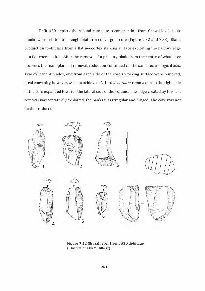
261
Refit #30 depicts the second complete reconstruction from Ghazal level 1; six
blanks were refitted to a single platform convergent core (Figure 7.52 and 7.53). Blank
production took place from a flat neocortex striking surface exploiting the narrow edge
of a flat chert nodule. After the removal of a primary blade from the centre of what later
becomes the main plane of removal, reduction continued on the same technological axis.
Two débordant blades, one from each side of the core’s working surface were removed,
ideal convexity, however, was not achieved. A third débordant removed from the right side
of the core expanded towards the lateral side of the volume. The ridge created by this last
removal was tentatively exploited, the banks was irregular and hinged. The core was not
further reduced.
Figure 7.52 Ghazal level 1 refit #30 débitage. (Illustrations by Y. Hilbert).

262
Figure 7.53 Ghazal level 1 refit #30. (Illustrations by Y. Hilbert)
Refit #31 is a relatively complex constellation; relative given that no complex
technological procedures such as crest preparation or core tablet technology have been
applied. It is complex in that a great number of blanks were produced using the core at
hand and that during the early stages of core reduction; different platforms and planes of
removal have been created and exploited. A loaf shaped chert nodule served as a starting
point for this reduction (Figure 7.54).

263
Figure 7.54 Ghazal level 1 refit #31 débitage. Stage a (Illustrations by Y. Hilbert).
Initial reduction of the core commenced by creating a striking platform on the left
side of the chert nodule; two consecutive flakes, one of them a cortical flake, were reduced
creating the first used striking platform. Reduction proceeded on the narrow, long face of
the nodules. Using the same striking platform a second large cortical flake was reduced
from the left periphery of plane of removal (Figure 7.55).
The plane of removal was, in the second stage of reduction, converted into a
striking platform from which reduction took palace perpendicular to the previous removal
on the last core’s working surface (Figure 7.56). A set of approximately four primary flakes
and blades were reduced.

264
Figure 7.56 Ghazal level 1 refit #31. Stage c (Photograph by Y. Hilbert)
Figure 7.55 Ghazal level 1 refit #31. Stage b (Photograph by Y. Hilbert)

265
Reduction then shifted back to the first striking platform removing the one crested
blade in the level 1 assemblage. As stated earlier, the refit shows that the creation of this
typological element was by no means related to crested blade technology. The crested
blade was the result of the removal from the intersection of the previously used striking
platform and plane of reduction administered transversely to the previous technological
axis of the core. That is to say change in reduction axis, a feature also observed in level
2 refit #20, serves the optimal usage of the volume available to the flintknapper at
Ghazal Rockshelter. The further exploitation of the currently used core’s working surface
continued until the core was exhausted, manifested by the flat plane of removal. Attempts
to expand the working surface towards the right side (viewed in technological axis) of the
nodule failed due to repeated hinge fractures. At this point the last change of orientation
and conversion of the plane of removal into a striking platform took place (Figure 7.57).
Figure 7.57 Ghazal level 1 refit #31. Stage d (Photograph by Y. Hilbert).

266
From this point on reduction continued conform to the technological axis, no plane
of removal curration elements, débordant blades or flakes, were produced and reduction
proceeded in volumetric fashion until the core was abandoned (Figures 7.58 and 7.59).
Figure 7.58 Ghazal level 1 refit #31. Stage e (Photograph by Y. Hilbert)
Figure 7.59 Ghazal level 1 refit #31. Stage f (Photograph by Y. Hilbert).

267
7.3 BRAVO Transect Comments
7.3.1 Khumseen Rockshelter
The results of the attribute analysis of the lithic assemblage from the leptolithic
levels of Khumseen Rockshelter point to intensive blank production, using unidirectional
parallel technology. Although post-depositional factors have skewed the sample to a
certain extent, the main modalities of reduction used at the site have been crystalized.
Chiefly dictated by the recurrent reduction of blades, flakes and bladelets, with discreet
interconnected convex maintaining and creation phases, cores have been exploited up to
the point were the sheer size of these specimens did not support the further reduction of
leptolithic débitage. That is to say, cores and their volumes were reduced to full exhaustion
or were prematurely abandoned due to botched working surfaces.
Variability identified among the three main débitage categories found at the
site indicates some degree of specialization towards the deliberate production of
blades, flakes and bladelets. While all three blank types were produced using single
platform unidirectional cores, the progression of the reduction cycles of these blanks is
deemed responsible for a shift from blade production to flake and bladelet production.
Short bladelets with twisted and straight profiles have been struck from unidirectional
convergent cores with relatively short, broad working surfaces. The exploitation of
additional volume on globular multiple platform cores yielded primarily short blades and
elongated flakes.
The tool spectrum, although small and unilateral considering the lack of variability
includes two projectile points, which can now, based on the dates, be ascribed securely to
the Early Holocene.
7.3.2 Ghazal Rockshelter
The Ghazal rockshelter assemblage is composed of two samples, both characterized

268
by the production of elongated blanks; the samples are separated stratigraphically by a
sterile sand layer. Although no absolute dates for the actual occupations of the site could
be produced (e.g. fireplaces, organic remains which would have yielded C14 dates were
missing), the OSL samples retrieved from the GH bracketing the level 2 industry provide a
fair chronological marker for that layer and the one above. Spatially, both industries were
confined to different areas within the excavated perimeters; level 1 being constrained to
the areas within and in the proximity of the small overhang, while level 2 artefacts were
found mainly in front of the rockshelter.
Although limited in numbers, both assemblages revealed, based on the refits,
similar patterns of blank production, but some variability in regard to core workings
surface use. Débitage attribute analysis revealed nearly identical patterns for both
levels; blades produced from simple unidirectional cores using ridges across the plane of
removal as guiding element’s following the technological axis of the cores. The creation
and maintenance of these ridges was aided by the removal of débordant from the cores
peripheries. Two modes of convexity exploitation have been observed; a recurrent
approach, based on refit #19 from level 2 and refit #28 from level 1 and the approach visible
in refit #25 and refit #30. The recurrent approach makes use of the created convexity by
reducing a set of blanks, while the second approach is so designed that a single elongated,
triangular shaped blanks is achieved from the core’s working surface. While the recurrent
approach is composed of a long sequence, starting from convexity creation to blank
production and subsequent exhaustion of the plane of removal, the second approach is
marked by short alternation exploitation and convexity creation phases.
Also repeatedly observed in both levels is the tendency towards shifting core
architecture, in that the striking platform becomes the plane of removal and vis a versa;
examples for this behaviour are seen in level 2 refits #2 and 20 and level 1 refit #31.
The tool sample for level 2 (level 1 is devoid of any modified blanks) is discreet
but concrete; a burin, an endscraper on a thick blank and a piercer have been found.

269
As such, the reduction modalities and the tools identified within the stratified
sites of the BRAVO transect can be found within surface sites all over the Nejd Plateau.
Wadi Haluf, a particularly rich zone within the southern Nejd has produced a high density
of Nejd Leptolithic sites. The perusal of the stone tools retrieved from the GULF transect,
which has been laid across the Wadi Haluf valley should help to further define technological
and typological plasticity within the Nejd Leptolithic technocomplex.

270
Chapter 8
GOLF TRANSECT
While the data gathered from BRAVO transect allows for a chronological
categorization of the lithic samples collected from the sites found along the ALPHA
transect, sites found along the GULF transect are used to further grasp technological and
typological plasticity within the here defined entity. This chapter will finalize the data
section of this dissertation. In addition to the systematic surface collection undertaken
at Wadi Haluf 1 (TH.124b), three localities identified along the GOLF survey transact are
of interest to this study, given the core reconstructions these provided (Figure 8.1). The
transect laid at Wadi Haluf served to assess the archaeological potential of this landscape
and identify its chrono-cultural variability, based on the recognition of typological and
technological diagnostics artefacts on the surface.
Figure 8.1 GULF transect and sites mentioned in text.Wadi Haluf 1 N 17.383920° and E 53.929160°, TH.125 N 17.386570° and E 53.935750°; TH.128 N 17.390490° and 53.940030°; TH.133 N 17.396790° and E 53.941460°(Satellite image courtesy of Google© Earth).

271
Of the 31 recorded sites along the 4.3 km of the GOLF transect, twenty have been
attributed to the Nejd Leptolithic tradition. The GOLF transect was so placed that diverse
micro-areas between Wadi Haluf and Wadi Haylah, one of wadi Haluf’s tributaries to the
north, could be surveyed. Starting within the wadi valley, the transect continued over
the southwestern facing cuesta of Jebel Ardif up to a dissected low plateau. This heavily
dissected plateau was rich in both raw material outcrops and archaeological sites. The
transect ends at wadi Haylah, which joins wadi Haluf further north.
8.1 Gulf Transect Sites
8.1.1 TH.125
The TH.125 occurrence was found on the southwestern facing cuesta of the plateau
adjacent to the Wadi Haluf valley (Figure 8.2). The scatter, composed of seven débordant
blades and one single platform unidirectional core, was spatially well delimited. No raw
material source was found in the proximity of the scatter. The patination observed on the
artefacts is of dark brown colour. No edge damage was observed on the blanks or the core,
suggesting little to no post-depositional movement or trampling of the scatter.
Figure 8.2 Photograph of TH.125 locality. Y. Hilbert working on the core reconstruction in the field. (Photograph by Dr. J. Rose)

272
All artefacts could be refitted revealing a succession of core preparations and
exploitations phases. No early decortication flakes or striking platform preparation
débitage was found, suggesting that the core received some treatment prior to the
deliberate blank production at the TH.125 locality. It is conceivable that decortication and
striking platform preparation was undertaken at the raw material source and that the
prepared core was then transported to the locality (Figure 8.3).
Figure 8.3 TH.125 refitting débitage.(Illustration by Y. Hilbert)

273
The seven blanks exhibit very similar morphologies. Striking platforms are plain
and received little treatment prior to blank detachment. Bulbs of percussion on the ventral
surfaces are prominent, suggesting the use of hard hammer percussion. Two of the blanks
had missing striking platforms and, given that these have been reduced just like the other
débitage, it is conceivable that these share the same morphological features. All blanks
exhibit cortical backs, these have been found to be in an approximate 90° angle to the
dorsal surface, allowing the classification of these objects as débordant blades. Five of
these were found to share the same overpassed terminations, lateralized blank shapes
and trapezoidal midpoint cross-sections, as well as curved longitudinal profiles. The two
other blanks with feathered terminations and parallel edges complete the débitage. All
débordant blades exhibit a unidirectional convergent scar pattern.
The core exhibited a plain striking platform in concordance with the pattern
observed on the blanks; the longitudinal disposition of the dorsal face is straight, while
horizontal convexity is still somewhat present. The core’s working surface is positioned
on its frontal plane with no indications of any additional working surfaces.
As noted above, decortication and platform preparation have been undertaken
elsewhere, reduction undertaken at the TH.125 occurrence was restricted to deliberate
blank production and successive convexity maintenance procedures (Figure 8.4). Reduction
started with the removal of débordant elements; this removal created a dihedral working
surface on the core. A central ridge served as guiding ridge for the preferential removal of
an elongated blade with convergent edges. This blank was not found at the site and had
been purposefully removed for further modification elsewhere. The subsequent removal,
undertaken on the opposite side of the core, re-established the dihedral morphology of
the core’s working surface and was followed by an additional preferential removal. The
negative visible on the reconstructed core gives an idea of what the desired products
created by this recurrent reduction looked like. A third débordant element was removed
from the right edge of the core and was also followed by the removal of a triangular and

274
Figu
re 8
.4 T
H.1
25 r
efit
ting
. (Ill
ustr
atio
n by
Y. H
ilber
t)

275
elongate blank. After this step, the core’s working surface presented two ridges converging
in the bottom portion of the flaking surface. Two successive removals, one from the left
and one from the right side of the core served to re-establish the dihedral working surface.
The ridges created by these removals served the reduction of a cortex free elongated blank
with triangular cross-section. The reduction of the core continued after re-establishing
the guiding ridge. One last débordant element was struck, followed by the removal of an
elongated triangular blade from the centre of the core. Given the cores flat working surface
morphology and increased volume loss, the piece was abandoned.
8.1.2 TH.128
The TH.128 surface scatter is located on top of a low plateau upon Jebel Ardif.
The plateau is dissected by several erosional gullies that cut into the limestone bedrock.
A deflated surface composed of eolian material, limestone debris and both worked and
unworked chert covers the plateau (Figure 8.5). Raw material is available and of high
quality, nodules of medium to large size are present and were used to produces stone tools.
Artefacts found at the site were manufactured exclusively on the chert cropping from the
gahit member. The site itself is a medium to low density workshop much like Wadi Haluf
1, only less extensive. It is marked by a discontinuous flint carped that stretched over
approximately 60 square metres.
Figure 8.5 Photograph of TH.128 locality. (Photograph by Y. Hilbert)

276
Blade manufacture was the most common form of reduction used on site. Survey
activities undertaken at TH.128 have revealed the existence of a façonnage component,
attested by the presence of a bifacial pre-form (Figure 8.6). Unlike the immediate refit
from TH.125, the scatter at TH.128 was not entirely isolated, but recovered from a carpet
of artefacts, geofacts and limestone shatter. Nonetheless, the combined effort of three
DAP team members for over 30 minutes produced the reconstruction of a flint nodule
composed of a core and nine pieces of débitage.
Figure 8.6 Photograph of TH.128 biface. (Photograph by Y. Hilbert)
The refit illustrates all phases of blade production undertaken on one raw material
nodule (Figures 8.7 and 8.8). Artefact patination observed on site is of dark to light brown
colour; the variation spectrum and additional surface modifications observed have been
found indicative of chronologically constrained knapping events.

277
The core recovered exhibited a main working surface extending across half its
circumference. The core exhibits a cortical back, whereas the frontal working surface was
formed by five unidirectional parallel to sub-parallel removals. Longitudinal convexity
had been exhausted due to an overpassed removal that detached part of the core’s distal
portion. The débitage collected includes four débordant blades, three cortical blades
and two blades. Blank size varies greatly; the largest pieces were detached after initial
decortication, while two smaller blades were removed at the end of the core reduction.
The core reconstruction is incomplete, possibly three to four pieces had been removed
from the site.
Figure 8.7 TH.128 refitting débitage.(Illustration by Y. Hilbert).

278
Figu
re 8
.8 T
H.1
28 r
efit
ting
. (I
llust
ratio
n by
Y. H
ilber
t).

279
Reduction started with the decortication of the nodule’s narrow edge, no
platform was set up, given that the nodule exhibited a natural fracture plane in a nearly
90° angle to the technological axis used for blank production. Subsequent to the removal
of the first cortical blade, a succession of three large débordant elements were struck,
two exhibiting overpassed terminations. The two initially reduced débordant blades were
removed from the left side of the core’s plane of removal. Subsequently reduction shifted
to the right side in order to correct the core working surface symmetry. These removals
left a keeled surface on the core’s working surface that was subsequently exploited. The
blanks removed from the central area of the core are missing from the refit. Based on
the negatives visible on the reconstructed plane of removal, the blanks would have been
elongated with converging edges and free of cortex. Interconnected with the production
of these elongated converging blanks, surface control detachments from the core’s lateral
peripheries would have maintained horizontal and longitudinal convexity.
As reduction progressed and the core’s working surface reached a point where
reduction could not continue without producing blanks with hinged terminations,
convexity restoration measures were initiated. Following the removal of an overpassed
débordant element from the core’s right edge, convexity was tentatively re-established.
The following removal would have presented a symmetrical triangular cross-section
and diamond shaped lateral edges. These pieces have been removed from the site. The
disposition of the blanks negative is used to infer the configuration of the desired end
products. The subsequently removed blank, however, exhibited an irregular shaped
silhouette. It’s cross-section, although trapezoidal, was equally asymmetrical. The
subsequently removed blank could not be found at the site; however, the following
removal was present and could be reattached to the core. The last removal gave the core
its deserved “deathblow”; this elongated débordant removal detached the cores distal
portion, spoiling the object’s symmetry beyond rectification. Reduction of the nodule
halted and the core was abandoned.

280
8.1.3 TH.133
The surface scatter TH.133 was found on a low primary terrace overlooking a
minor tributary of Wadi Haylah. The slope of a secondary terrace located three metres
above the primary terrace where the scatter had been identified served as raw material
source for the prehistoric populations occupying the site. Conform to the local geology,
large flint nodules with thin dark cortex have been found outcropping from the gahit
member.
The locality is characterized by a moderate- to high-density artefact cover, again
artefacts, geofacts and limestone shatter litter the surface of the site. Technologically distinct
blank production methods have been identified at the site, apart form the ubiquitous
production of elongated blanks, using a unidirectional single platform reduction, the
production of flakes from a flat face of flint nodules, using a radial reduction method was
observed. The undifferentiated flakes and radial cores had a lighter patination than the
blade vestiges found at the site. Also, as in most of the sites located in the immediate
proximity of a raw material outcrop, the technologically diverging blank production
modalities were found constrained and spatially separated from each other. Given the
technological divergence observed on the artefacts, TH.133 is considered to be the result
of two different groups separated in time and exerting diverse reduction strategies.
Considering the focus of this dissertation, collection and descriptions were limited to the
Nejd Leptolithic component of the site.
Refitting activities undertaken directly at the site revealed an artefact constellation
depicting the reduction of a core in its advanced stage of preparation. A total of six
elongated blanks and their corresponding core were collected and will be described here,
in order to help identify variability within the blade production used (Figure 8.9).
The core has a single unprepared flat striking platform, made up of a natural
fracture on the raw material nodule. The piece exhibits a cortical back and five unidirectional
parallel removals on its working surface, which is positioned on the narrow edge of the

281
raw material nodule. Horizontal and longitudinal convexities were completely exhausted.
The débitage pertaining to the constellation encompasses five débordant elements and
one blade. The débordant elements exhibit either overpassed or feathered terminations;
morphologically little variation is seen among the débitage. The single blade reattached to
the refit has parallel sides, a unidirectional scar pattern and an overpassed termination. All
débitage exhibit plain unprepared striking platforms consistent with the striking platform
observed on the core.
Figure 8.9 TH.133 refitting débitage. (Illustration by Y. Hilbert).

282
The refit does not mirror the complete reduction procedure, but an entire cycle
of reduction starting with the convexity maintenance procedures, the exploitation of
the created convexity and subsequent discard of the core were recorded (Figure 8.10).
Three débordant elements were reattached to the core, these have been removed between
convexity exploitation phases, as may be seen on the converging negatives visible on the
dorsal surface of the blanks reduced from the right edge. The débordant element struck
from left edge of the core’s working surface was detached earlier in the reduction process
and displays a single large unidirectional negative on its dorsal surface. The blanks
pertaining to the exploitation of the created ridges could not be found and were possibly
transported away from the site for further manipulation.
Figure 8.10 TH.133 refitting. (Illustration by Y. Hilbert)

283
The reduction of the débordant elements from both left and rights portion of
the core’s working surface created a keeled plain, which was then exploited. After two
elongated blanks with converging sides were detached and removed from the site, a
débordant element was removed from the right edge of the core, thus creating a centrally
running ridge on the core’s plane of removal. The overpassed blade reattached to the
central portion of the core, overshot the core’ working surface; nonetheless, the slightly
lateralized ridge created by this removal was used to produce an elongated blank with
converging sides. The last removal, a débordant blade detached from the cores left side
failed to restored convexity and the core was abandoned.
8.2 Wadi Haluf 1 (TH.124b)
8.2.1 Site Location
Found during the field season of 2011, the Wadi Haluf 1 site is located in the upper
portion of the wadi that bears the same name. Wadi Haluf runs north westwards from the
Dhofar Escarpment before joining Wadi Ghadun in the central region of the Nejd Plateau.
Running in a southeast to northwest axis, the wadi valley extends for approximately 35
km, measuring approximately 2,5 km wide at its broadest point. On its course across
the southern Nejd, Wadi Haluf dissects a rugged table landscape composed of tertiary
Limestone of the Rus Formation of the middle part of the Hadhramaut group. The wadi
course itself is currently dry, filled with fluvial detritus and partially covered by an eolian
blanket. The braided fluvial pattern visible in the dry wadi bed bears witness to a gradual
decrease in fluvial energy and the subsequent suffocation of the stream by fluvial detritus
and larger boulders. Adjacent to the dry wadi bed, a low and undulating plain, dotted with
inselbergs and dissected by small erosional gullies may be seen (Figure 8.11).

284
Figure 8.11 Wadi Haluf 1 photographs.scatter situation; 2 Wadi Haluf 1 find scatter (Photograph Dr. J. Rose and Y. Hilbert).

285
The site itself is situated on the eastern side of the wadi in the immediate proximity
of a group of low inselberg. These low hills have been identified as remnants of the Upper
Hadhramaut Group, more precisely to the gahit member. Colluvial detritus composed of
limestone shatter and chert nodules, supported by an eolian matrix, covers the piedmont
of these inselbergs. Very few artefacts have been found on the slopes; the majority of lithics
were found scattered across the undulating plain composed of fairly sorted and rounded
fluvial gravels of medium size (5-15 cm in diameter), covered by gypsum and blanketed
by a 5 -15 cm thick eolian carpet.
Wadi Haluf 1 is a medium to high-density surface scatter, covering approximately
300 square metres. Within this large surface site, smaller concentrations have been
detected. Raw material used and patination observed on the artefacts is very homogenous.
Given this uniform appearance, the lithics found at the site have been tentatively attributed
to a single cultural period, namely the Nejd Leptolithic (Hilbert et al., 2012).
8.2.2 Sampling strategy and documentation
In order to sample the Wadi Haluf 1 site, a spatially constrained grid was placed
over a concentration of artefacts. The 3 x 4 metre grid was divided into 1 square metre
units; all artefacts within these units were collected and the surface eolian cover excavated
for further “buried” artefacts. No artefacts were found lodged within the gypsum layer. All
artefacts found were subjected to lithic attribute analysis and refitting studies.
Prior to the artefact collection, each of the square metre units was photographed
in a nearly vertical angle. The twelve pictures were later arranged against one other, in
order to reconstruct the collected surface. Thanks to the photographic documentation of
the collected surface, the position and spatial relation between the refitted objects could
be traced, providing valuable information regarding spatial pattering at the site.

286
8.2.3 Spatial distribution
As noted above, the Wadi Haluf 1 scatters stretch across a large area and
undoubtedly has been deposited over a considerable amount of time. Unfortunately,
absolute dating methods could not be applied to the site, making a secure chronological
attribution of the lithic assemblage impossible; however, thanks to the spatial analysis
and the refits, relative chronological affinity between some of the artefacts collected from
the sampled area could be established.
The twelve square metres collected and documented for this study exhibit a large
number of artefacts found on the surface and slightly below the surface, averaging 41
artefacts per square metre (Figure 8.12).
Figure 8.12 Wadi Haluf 1 artefact density.(Image by Y. Hilbert)

287
Within these twelve units, fourteen refits have been made; their locations within
the sampled area are illustrated in Figure 8.13. Based on these refits and the intensified
distribution of artefacts within two higher concentration loci inside the collection grid,
the following statements may be made concerning spatial distribution: (a) artefacts
have suffered little post-positional displacement, (b) the different concentrations reflect
knapping events. The main concentration, based on the refits and artefact distributions,
was observed around squares B2 and B4. Refits have been successfully accomplished
between artefacts laying in squares A3, B1, b2, C1 and C2. The refits around B4 are less
numerous and possibly relate to a second concentration to the west of the collection area.
Figure 8.13 Wadi Haluf 1 spatial distribution. (Image by Y. Hilbert).

288
8.2.4 The assemblage
In total, 590 artefacts were recovered, including thirteen cores, three tools, and
574 pieces of débitage (Table 8.1). Of these 574 pieces of débitage, 76 were classified
as chips, leaving a total of 498 débitage elements on which attribute analysis have been
undertaken.
TOTAL n %Flakes 93 16Blades 164 28Bladelets 13 2Cortical Flakes 51 9Cortical Blades 50 8Débordant Flakes 18 3Débordant Blades 107 18BTF 2 0,5Chips 76 13Cores 13 2Tools 3 0,5
Total 590 100
Table 8. 1 Wadi Haluf 1 artefact count.
Blades and débordant blades are by far the most numerous types of débitage found
within the assemblage. Flakes are less numerous than blades and débordant elements
accounting for only 16% of the débitage. Cortical elements, as in cortical blades and flakes,
are slightly more numerous than flakes and make up 17% of the blanks.
Only thirteen cores were found within the assemblage. The low core to débitage
ratio of 1:44 is noteworthy, possible reasons for this will be discussed later. Three tools
were found at the site and will also be discussed here.
Blank production using varying modalities of unidirectional parallel reduction
was the main activity undertaken at the site based on the débitage analysis. To a minor
extent, the production of trifaces is attested by two bifacial thinning flakes and a triface
preform collected in the proximity of the sampled area.
Raw material and patination are very homogenous; all artefacts were made of
chert nodules outcropping from the gahit member. Chert nodules found in the proximity

289
of the collection area show the same characteristics as those observed on the collected
artefacts. Raw Material varies in dimension from kiwi- to watermelon-sized nodules,
usually displaying an nearly ovoid cross-sections. The cortex is thin and smooth textured,
displaying dark hues of colour. When found directly cropping from the limestone, the
cortex exhibits lighter shades of brown and slightly courser texture. Freshly knapped
pieces of this raw material exhibit a light grey colour, while the archaeological material is
dark grey with shadings of dark yellow.
8.2.5 Débitage
As noted above, blank production was the most frequent activity undertaken at the
site. No severe edge damage was found on the débitage, suggesting little post-depositional
displacements by erosional forces; attesting to a fairly undisturbed sample. Although no
trampling fractures have been observed on the artefacts, breakage is considered high
among the débitage. The three most significant blank classes within the assemblage,
débordant blades, flakes and blades, exhibit a high amount of breakage. Of the 164 blades
found at the site only 70 (57%) were found to be complete. Flakes were less fractured;
63% of all flakes (n=59) were complete. Débordant elements were even less fractured
than flakes; of the 107 débordant blades 73% (n=78) were complete.
The ratio of cortical elements (cortical flakes and cortical blades) to non-cortical
is 1:4, indicating that on site decortication took place; 72% of the blades (n=116) have
between 0% to 10% of cortical cover. Flakes show a similar pattern, a total of 60% (N=55)
have between 0% to 10% of cortical cover. Both blades and flakes have generally less
dorsal cortical cover. Débordant elements, regardless weather flake or blade proportioned,
show higher amounts of dorsal cortical cover. In total, 51% of the débordant blades (n=54)
exhibit 11% to 25% of cortical cover; the second most numerous, with 44% (n=47), are
the débordant blades with 26% to 50% of cortical cover. As for the débordant flakes, of the
eighteen found, eleven (61%) show between 11% and 25% and six (33%) between 26%

290
and 50% of cortex cover, consistent with the pattern observed on the débordant blades.
The thirteen bladelets and two BTFs exhibit no or only very little cortex.
Débitage platform morphology is painstakingly uniform, striking platforms are
predominantly plain. Cortical elements, blades and flakes show minimum variability in
striking platform disposition, in that only four flakes display faceted striking platforms
and two display dihedral striking platforms. Blades are less variable, only two dihedral
striking platforms have been observed. Two of the 51 cortical flakes had faceted striking
platforms. The débordant elements and the bladelets display plain striking platforms,
while the two identified BTFs show either faceted or crushed striking platforms.
Striking platform dimension analysis based on IPF indicated that blank platforms
are wider than they are deep. Flake striking platforms have show the highest amount of
variability (s.d. 1,16 avg. 2,69). Blades and débordant blades exhibit identical average IPF
values (avg. 2,33). Débordant blades exhibit greater variability based on the standard
deviation values (s.d. 0,73). Cortical elements produced diverging IPF; pieces with flake
proportions exhibit a higher average value (avg. 2,48) than the blade proportioned cortical
elements (avg. 2,24).
Débitage mid point cross-section shows little variability. Flakes, blades and
débordant blades possess mostly trapezoidal cross-sections, respectively, 30%, 42% and
59% (n=30, n=68 and n=63). Débordant blades with trapezoidal cross-sections have one
cortical lateral edge; also observed among the débordant blades were equal amounts of
triangular and triangular lateralized cross-sections (16%, both n=17). To a lesser extent,
débordant blade’s midpoint cross-sections had in 7% (n=7) of the observed cases more
than three vectors. Blades presented a high percentage of pieces with triangular cross-
section totalling 33% (n=54). Such cross-sections are indicative for the use of a guiding
ridge left on the core’s working surface by previous removals. Flakes have a wider range
of midpoint cross-sections: 19% were flat (n=17), while triangular and triangular lateral
steep cross-sections were observed in similar percentages (19%) in the flake sample

291
(n=15 for both triangular and triangular lateral steep). The thirteen bladelets found at
the site display to a greater extent triangular cross-sections (n=9) and to a lesser extent
trapezoidal or more than three vectors (n=3 and n=1). The bifacial thinning flakes have
been found to possess either flat or more then three vector cross-sections.
Flakes and blades show similar longitudinal cross-sections: 54% and 50%,
respectively presented flat profiles(n=43 and n=67). While 27% of the flakes (n=21) have
curved profiles, only 19% (n=26) of the blades have such a pattern. Blades show a greater
number of specimens with twisted longitudinal cross-sections (n=41). Such a pattern
indicates that blades were removed from guiding ridges positioned at the lateral periphery
of the core’s working surfaces. Débordant blades have shown a contrary pattern; 42% of
the débordant blades have curved longitudinal profiles (n=43). Flat and twisted profiles
occur on 26% (n=26) and 32% (n=33) of the débordant blades, respectively.
The distal terminations observed on the débordant blades has been found to
be overpassed in 38% (n=38) of the observed cases. Both the distal termination and
longitudinal profile of the débordant elements indicate the use of these removals as core
working surface convexity correction measures. A greater portion of these débordant
blades, 53% to be exact, exhibit feathered terminations (n=52), indicating that the overshot
character observed on some of these blanks is not a desired feature but more the result
of excessive force in the blank removal procedure. Additionally, a logical consequence of
the overpassed termination is the reduction of the core’s working surface; representing
volume that can no longer be purposefully exploited. Only 9% of the débordant blades
possess hinged terminations (n=8).
Flakes and blades have similar blank termination types, as do the débordant
elements; feathered terminations have been found on 60% of the flakes and on 73% of
the blades (n=47 and n=80). Hinged terminations were observed on 31% of the flakes and
on 18% of the blades (n=24 and n=20), while overpassed terminations were recorded on
fewer pieces; both 9% (respectively n=7 and n=10).
292
The percentage of pieces detached off axis has been found to be relatively balanced
among the three main débitage types found at Wadi Haluf 1; 29% of the flakes and 23%
blades were struck in off axis (n=18 and n=19). Débordant blades percentages were found
to be slightly higher with 35% of the observed cases struck off axis (n=29).
Blank shape has been found to be predominantly rectangular, displaying parallel
edges; nonetheless, some differences among the débitage classes have been observed. The
three major débitage classes have mostly parallel edges, 38% of the flakes (n=35), 50% of
the blades (n=80) and 37% of the débordant blades (n=40). The elongated débitage has
a higher percentage of pieces with converging sides, 23% of the blades (n=37) and 20%
of the débordant blades (n=21) present a triangular silhouette (Figure 8.14). Additionally,
débordant blades exhibit in 17% of the cases a lateralized silhouette (n=18), a slightly
higher percentage when compared to flakes and blades where only 6% and 7% have such
a shape (respectively, n=5 and n=11). While 18% of flakes and 19% débordant blades
(respectively, n=16 and n=20) exhibit expanding edges, this shape is seldom observed
among blades; only 9% have this shape (n=15). To a lesser extent, the three main débitage
types exhibit either ovoid or irregular lateral morphologies. Débordant flakes exhibit either
expanding or lateralized edges, while bladelets are exclusively rectangular or triangular in
shape. Of the two BTF, one exhibits lateralized shape, while the other is of irregular shape.
Flake, blade and débordant blade dorsal scar patterns are marked by the
prevalence of the unidirectional scar pattern over the other configurations. A total of 66%
of all flakes, 67% of the blades and up to 82% of the débordant blades have this particular
scar pattern (respectively, n= 60,n= 107 and n=88). Flakes have greater variability;
unidirectional crossed, parallel and convergent have been observed on 8%, 12% and
7% (n=7, n=11 and n= 6) of the flakes. A small number of flakes have bidirectional or
transverse scar patterns: respectively, 2 and 7% (n=2 and n=5). Blades have a slightly
higher percentage of unidirectional convergent over unidirectional parallel scar patterns;
while 17% are convergent, 14% of all blades show unidirectional parallel scar patterns

293
(n=27 and n=22). Only 2% have unidirectional crossed patterns (n=4). Débordant blades
have the lowest amount of variability; blanks have either unidirectional parallel (12%),
convergent (5%) or bidirectional (1%) scar patterns. The few bladelets found within the
sample exhibit unidirectional scar patterns. The BTF’s possess bidirectional or opposed
oriented scars (Figure 8.15).
Figure 8.14 Wadi Haluf 1 débitage. 1 to 3 convergent blanks with complex cross sections and unidirectional convergent scar pattern; 4 and 5, blades with parallel sides and unidirectional scar pattern ; 6 and 7, flakes removed from the central portion of the core working surface (Illustration by Y. Hilbert)
12 3
45 6 7

294
Metrical variability expresses a clear divergence in dimensional configurations
between each of the identified bank types. This is no surprise, considering that
classification of blanks into the main categories (flakes, blades, chips…) rests partly on
metrical observations. Average blank surface measurements indicate a tendency towards
the production of elongated end products, an equally expected fact when considering that
56% of the artefacts recorded have proven to be twice as long as they are wide. Cortical
elements are larger on average than the flakes, blades and débordant elements, while
blade débordant are larger and thicker than blades. Interestingly, relative platform size
(RPS) of débordant blades are higher than blade RPS (22,12 and 14,84), indicating that
débordant blanks surface size in relation to platform size is higher than that of blades. This
Figure 8.15 Wadi Haluf 1 BTF’s .(Illustration by Y. Hilbert)

295
feature sustains the segregation of these débitage elements as core surface enhancement
agents, while through the removal of these pieces a large portion of the core’s working
surface was transformed, core platforms suffered less decrease in relative size.
8.2.6 Cores
The thirteen cores collected from the Wadi Haluf 1 sampling area mirror the
configuration of the débitage. The majority of these artefacts (n=10) are unidirectional
single platform parallel blade cores. Platform preparation was kept minimal; six of the
examined cores of this class possess straight striking platforms created by a single blow.
The remaining four unidirectional parallel cores have natural plain striking platforms.
Core flaking surfaces were either placed on a narrow edge of a flint nodule (n=3) or on a
frontal face, with an additional supplementary lateral working surface (n=4). To a lesser
extent, working surfaces were set up in a convex manner across the core’s frontal face to
one of its lateral faces (n=2) or on a frontal plain with two additional working surfaces,
one of each side of the core (n=1). All except one single platform unidirectional parallel
core exhibited faulty longitudinal convexities; four cores had working surfaces ruined
by overshot removals. Three cores had flat working surfaces, showing no indication of
attempts to re-establish horizontal and longitudinal convexities, two had working surfaces
covered by severe hinge fractures. Cores have elongated working surfaces, conforming to
blade production (Figure 8.16). On average, unidirectional parallel cores weigh 427,2 g,
with cores presenting additional working surfaces, either on one or both sides, weighing
less then other cores. Unidirectional parallel cores were, on average, 82,58 mm in long,
58,22 mm wide and 60,6 mm thick.
A two unopposed platform core was found among the assemblage. This specimen
is a textbook example of this core type as observed among the Nejd Leptolithic tradition
(Figure 8.17). Similar to the unidirectional parallel blade cores, the two unopposed
platform core has been exploited after minimal preparation; two opposed natural plain

296
striking platforms were used. The reduction surfaces were placed on opposite faces of the
core, thus creating two separate unidirectional parallel working surfaces on one nodule.
Both surfaces exhibit exhausted lateral and longitudinal convexities. Metrically, the core
fits well within the pattern observed for the unidirectional parallel blade cores.
Figure 8.16 Wadi Haluf 1 cores. 1, 2, 4 and 5 unidirectional parallel cores; 3 core on blank. (Illustration by Y. Hilbert)
The two remaining cores have been deemed preforms, based on the early stage of
reduction; both exhibited fewer than three negatives.

297
Figure 8.17 Wadi Haluf 1 two unopposed platform core. (Photograph by Y. Hilbert)
8.2.7 Tools
Three tools were found in the collected area: two informally retouched blanks
and one simple endscraper (Figure 8.18). The end scraper was made on a curved blade;
unfortunately the piece is incomplete, only the distal retouched portion of the tool
was found. Retouch was done by direct percussion and was steep. The two remaining
retouched objects were manufactured on blades; both pieces received normal retouch
across one third of the blades lateral sides. The retouched edge on one of these gave the
piece a slightly concave working edge.

298
Figure 8.18 Wadi Haluf 1 tools.1 and 2, retouched blades; 3, endscraper (Illustration by Y. Hilbert).
Two additional tools were found in the proximity of the collection area; one triface
preform and a triface (Figure 8.19). Although association between these objects to the
manufacturers of the blades found at the site must remain questionable, little indicates
that there is any contamination of the site by either older Palaeolithic or younger Neolithic
components. Supporting the triface manufacture at Wadi Haluf 1, a series of flakes
presenting faceted striking platforms were found in the collection area. These pieces did
not present morphologies associated with classical biface production. Most of these pieces
have opposed to bidirectional scar patterns and flat longitudinal cross-sections.

299
Figure 8.19 Wadi Haluf 1 trifaces. 1, triface preform made on large blade; 2 triface fragment. (Illustration by Y. Hilbert)
8.2.8 Refits
A total of fourteen refits and conjoins have been made; of these, refit # 14
provided the greatest amount of information. Refit #14 shows seven blanks refitted to a
single platform unidirectional core (Figures 8.20 and 8.21). The core’s striking platform
was created by the removal of a large cortical blade. Two débordant elements reduced
from the same side of the core’s central plane of removal were detached. Subsequently,
one débordant flake was detached from the opposite side of the core’s plane of removal.
Afterwards, one overshot and twisted, irregularly shaped blade was removed from the
centre of the core’s working surface. Then, two blanks were removed; these were not

300
present at the site. The negatives of the subsequent removals indicate that these were
regular in shape (parallel sides) and possibly represented desired products. Further
reduction along the centre of the plane of removal took place; two blades were removed
of which one was present at the site, while the other not. The last blank removed from
the core was a flake from the centre of the core’s working surface. At this point the dorsal
convexity had been exhausted and the flake had a hinged termination.
Figure 8.20 Wadi Haluf 1 refit #14 débitage.(Illustration by Y. Hilbert)

301
Figure 8.21 Wadi H
aluf 1 refit #14. (Illustration by Y. H
ilbert)

302
Refit #1 and #5 depict isolated phases within the reduction of individual cores;
based on these refits, interpretation regarding these particular phases are strengthened.
Constellation #1 is marked by two débordant blanks refitted to a single platform
unidirectional parallel core (Figure 8.22). The two débordant blades are of different size;
the larger piece was reduced during an early reduction cycle, while the later blank likely
represents an attempt to restore the core’s convexity. The last removal did not considerably
alter the core’s convexity, resulting in the abandonment of the core.
Figure 8.22 Wadi Haluf 1 refit #1.(Illustration by Y. Hilbert)

303
Constellation # 5 is composed of three débordant blades refitted to a single
platform core (Figures 8.23 and 8.24). After a cortical blade was removed (piece present),
two unidirectional removals followed (pieces are missing from the site). Subsequently,
a large blank was detached from the core’s lateral edge (piece was also not found). The
first débordant was removed, followed by unidirectional removals exploiting the created
convexity on the core’s working surface. In order to restore convexity, the last débordant
was removed. All refitted blanks were removed from the supplementary platform located
on the core’s right side.
Figure 8.23 Wadi Haluf 1 refit #5 débitage. Above (Photograph by Y. Hilbert)
Figure 8.24 Wadi Haluf 1 refit #5. Left (Photograph by Y. Hilbert)

304
Refits #2, #3, #7, #8, and #9 depict phase refits where two débordant blades are
attached one onto the other; all refitted blanks have overshot terminations. Between these
débordant detachments a convexity exploitation removal took place; the negatives on the
lateral, non-cortical peripheries of the refitted débordant blades supports this notion.
Refit #4 mirrors the removal of two cortical flakes from a nodule, presenting two
opposed cortical platforms. These two reattached removals were the only modification
the nodule suffered.
Refit #6 shows a blank reattached to a core. A large overpassed and twisted
débordant flake was removed from the frontal face of a unidirectional parallel core. After
that removal the piece was further reduced on its narrow side and then discarded due to
ruined convexity. The remaining refits (#10, #11, #12 and #13) are conjoins of fragmented
débitage.
8.3 GOLF transect comments
8.3.1 TH.125, TH.128 and TH.133 refits
The selective sampling undertaken at TH.125, TH.128 and TH.133 sites of the
GULF transect have produces valuable refits that help established variability within the
unidirectional parallel reduction method of the Late Palaeolithic. These three constellations
additionally allow the identification of past economic patterns. It has been shown that the
creation of convexity and the exploitation of this created convexity are intertwined within
a reduction continuum. The removal of débordant elements, in most cases, was followed
by the production of an elongated converging blank. These pieces have not been found
at the sites, although the reconstruction of the TH.125 refits indicates that at least five of
these blanks were produced.
In regard to the raw materials exploitation and handling strategies used, varying
strategies have been observed: (a) Cores were prepared and used to produce desired

305
blanks at a given site. Cores and blanks are transported away from this primary site;
subsequently, the core is further reduced at a secondary site. Desired blanks are removed
from the site for further processing. (b) Cores are prepared and exploited directly at the
site and only blanks are removed from the site.
Although valuable for the reconstruction of such patterns, insecurity regarding
the absolute chronological placement of these artefacts should not be underestimated.
An attribution of these constellations to the Nejd Leptolithic tradition is possible thanks
to the identification of identical technological patterns in stratified and dated contexts
(Ghazal, Khumseen and al Hatab rockshelters).
8.3.2 Wadi Haluf 1 comments
At Wadi Haluf 1 a very simple and prolific blade production technology was
identified. Both blades and flakes collected at this surface scatter come from simple
unidirectional single platform cores, as indicated by the dorsal scar patterns and blank
striking platform morphologies. Metrical analysis support this statement in that the
average index of elongation of all complete débitage collected is 2,35 (n=330), indicating
that these are at least twice as long as they are wide. Considering the high number of hinge
terminations among the flakes, which is indicative for core convexity loss, these débitage
elements have likely been reduced, while working surface configuration was poor.
All phases of core preparation and exploitation have been observed at the site. The
large numbers of decortication blanks indicate that this process was administered on site.
As seen on the refits, particularly refit #14, core convexity maintenance phases preceded
the exploitation of parallel to convergent shaped, elongated blanks with triangular to
trapezoidal cross-section. Débordant elements with small striking platform dimensions in
relation to blank size fulfilled that purpose. The low core to débitage ratio of 1:44 mirrors
the efficiency with which the cores have been reduced. Also, it is likely that “Vollkerne”
(Hahn, 1993), prepared cores, were extracted from the sample by the flintknappers and

306
further reduced elsewhere.
The few tools provide little indication of the activities additionally undertaken at
the site. The few façonnage elements, preforms and thinning flakes, are the only indications
of any technologically divergent procedure undertaken at the site.

307
Chapter 9
CONCLUSIONS
… an Arabian assemblage may fall into one of two different inter-regional contexts:1. An assemblage’s immediate origin is to be found in an adjacent region. This would show in clear technological and typological patterning that closely parallels patterning from a near contemporaneous industry in an adjacent region.[...] 2. An assemblage’s immediate origin lies in Arabia. Its technological and typological patterning most closely parallels earlier local assemblages that show no direct, specific parallels with any industry from an adjacent region.
−Anthony E. Marks, The Paleolithic of Arabia in an inter-regional Context
I have learned more over these three years of research than I have written, and I
have written more than I had planned. This is primarily due to the sheer number of sites
mapped and sampled during the 2010-2012 DAP field seasons. A lot of rocks make for a
lot of data and, consequently, a lot of written pages. This chapter aims to synthesize these
data and attempts to draw some conclusions from the various threads of information
presented throughout this dissertation.
This study has conducted technological and typological analyses of diverse
samples from different sites generally classified as Nejd Leptolithic. Concerning the Nejd
Leptolithic, Rose (2006) writes that:
These assemblages seem to represent a widespread blade industry observed at a number of findspots throughout the Nejd Plateau. The term Nejd Leptolithic is used, although in the absence of an in situ type site, this taxonomic designation should not be considered a proper industrial label. (Rose, 2006, 283)
So, at this stage the Nejd Leptolithic should be viewed as a loosely defined lithic
technocomplex, sensu latu, encompassing multiple industries that share one or more
specific technological elements over a span of time (Kleindienst, 1967; 2006). The four
major sites analysed and presented in chapters Six to Eight: Ghazal and Khumseen
Rockshelters, Jebel Eva and Wadi Haluf 1 surface collections, all fall within one specific

308
industry of the Nejd Leptolithic technocomplex or tradition. The analysis of the lithic
material and the absolute dating of the associated sediments allow for the description and
chronological attribution of a specific technological package shared by the assemblages
collected from these sites. The data collected from the localities TH.125, TH128, TH.133,
and TH.59 will also be discussed regarding their technological variability, stone tool
typology, and extrapolated economic behaviour.
Following a description of the specific elements that constitute the Late Palaeolithic
assemblages presented here (e.g., technology, typology, raw material, economic behaviour,
etc.), climatic fluctuation found across the landscape of Dhofar at the Pleistocene/Holocene
divide is then considered. In examining intra-regional affinities over time, this study notes
parallels between MIS 3 and 2 sites found in the South Arabian Highlands and the Late
Palaeolithic sites presented here, hinting at Late Pleistocene demographic continuity in
the South Arabian Highlands. Given the paucity of archaeological data from MIS 3 and 2,
comparisons must be viewed as preliminary.
Bolstering the emerging archaeological picture of indigenous groups present
in South Arabia prior to the onset of the Holocene, additional evidence in the form of
genetic data are integrated into the discussion. This study considers the distribution
of mtDNA haplogroup R lineages found among modern groups throughout the South
Arabian Highlands and the estimated coalescence ages of these peoples. Finally, using the
archaeological evidence generated in this dissertation, implications of this Late Palaeolithic
industry are considered in reference to the Late Palaeolithic/Neolithic transition.
9.1 The Late Palaeolithic of Dhofar
Over the next pages, the data discussed and presented across this dissertation
will be summarized in order to classify one distinct lithic industry pertaining to the
Nejd Leptolithic technocomplex. The technological package composing any industry is
represented by the reduction modalities anchored within a technological system, which

309
is used to produce a relatively standardized array of stone tool types. This is particularly
significant, as it is the primary, if not only available material culture in prehistoric contexts
found across Dhofar. In other words, the débitage and cores found at a given site are
the products of a reduction system and raw material economy that is the most durable
expression of culturally transmitted behaviour in prehistory.
Stone tool technology found across sites pertaining to the same industry will,
therefore, be the same or show some degree of similarity. Variability between sites of
the same industry does occur (e.g. blank size, core, blank, and tool type frequencies),
but is often related to different raw material economies and site function, rather than
cultural variability. This variability is mainly expressed in artefact type counts and slight
differences in attributes. Within a given industry, however, these are but minor variations
from the overall technological pattern expressed by the cores and débitage contained in
an assemblage. Thus, on the whole, assemblages comprising a given industry will share
the same essential technological features aimed at producing an overlapping range of
tool types. The stone tools examined in this study provide enough insight to this aspect
of the material culture to help make the industry recognizable across the archaeological
landscape.
9.1.1 Reduction modalities
Blanks were almost exclusively produced by unidirectional reduction strategies.
This method of core reduction is dictated by a unidirectional recurrent and facial (sensu
Meignen, 1995; Delagnes, 2000; Hilbert et al., 2012) approach to the core’s volume
that was accompanied, in smaller parts, by a flexible and alternating use of additional
platforms and core working surfaces. For the purposes of this dissertation, the distinction
between parallel and convergent cores was made based on morphological parameters
(i.e., core and core working surface shape). The morphology of any given core found at a
site represents only the last phase of its reduction (e.g. Inizan et a., 1992; Andrefsky, 2005).

310
Thanks to the pristine character of both surface scatters and stratified sites, a number
of refittings have been made. These refits have been illustrated and described as to the
succession of removals and dynamic core morphologies through the reduction sequence.
These refittings show that both unidirectional convergent and parallel cores have been
produced using the same reduction strategies; unidirectional reduction method.
Consequently, the blank production sequences could be further divided into
three distinct reduction modalities based on evidence from core reconstructions. These
reduction modalities are defined by the refittings, which are distinct from one another;
two refits may depict the same reduction pattern but express it differently. This flexibility
emerges as a result of the flintknapper’s fluid technological gestures marked by successive
adjustments to the cores convexity, which are never absolutely reproducible but may be
classified into comparable stages within the chaîne opératoire. These phases of adjustment
are followed by phases of convexity exploitation. Thus, the differentiation of recurrent
single platform unidirectional reduction methods was achieved by identifying variability
within convexity maintenance measures applied to the core’s working surface.
The modalities presented here are schematics, which means that the attribution
of specific refits or débitage samples to any one scheme is inherently a generalisation. This
creates potential problems with borderline cases that sometimes must be shoehorned into
existing modalities, rather than creating additional modalities for every refit. Borderline
cases aside, however, the 85 refits made and analysed for this studied fit comfortably into
one of the three reduction modalities defined in this analysis.
Modality 1 uses a single plane of removal on a raw material nodule or block;
striking platform preparation is minimal and consists of one, maximum two removals from
the top of the nodule. Often, the striking platforms are flat cortical or fracture planes used
without any further preparation. Subsequently, débordant elements are struck from the
lateral edges of the core’s working surface to create a keel-like plane of removal (Figure
9.1). This convexity is then exploited by three to five elongated recurrent removals; after

311
the production of non-cortical débitage, the core convexity must be prepared anew.
Figure 9.1 Reduction modality 1 schematic.(Image by Y. Hilbert)
This reduction modality – the simplest of the three recognized reduction methods
– has been observed more frequently than the other two (Table 9.1). Refitting #14 from
Wadi Haluf 1 best depicts this specific variation; further examples were recorded for
localities TH.133, TH.128, Ghazal Rockshelter level 2 refits #2 and #5 and Khumseen
refit #11. Particularly at Ghazal, reduction modality 1 was used in an alternating fashion,
which means that after exhaustion of one working surface, an additional surface was
subsequently exploited on the same nodule. At Ghazal Rockshelter level 2 and Wadi Haluf

312
1, the identification of this particular reduction method allowed for the recognition of
technologically diagnostic débitage (sensu Monigal, 2002). These are by-products that
are indicative of a specific kind of reduction (Figure 9.2). In the case of Modality 1, the
technologically diagnostic débitage include débordant elements with cortical backs, as
well as triangular flakes and blades with flat profiles and complex midpoint cross-section
(trapezoidal, three vectored and pitched). These latter types are not preferential products
as identified with Levallois convergent technology (for examples of refits see Demidenko
& Usik, 1995). These are produced when the core’s working surface convexity must be
restored, achieved by the removal of a blank that eliminates excessive convexity. This
phase is often followed by the removal of débordant elements from the peripheries of the
core’s working surface in order to re-establish the desired convexity.
Figure 9.2 Technologically diagnostic débitage produced by Modality 1. 1, 4 to 6 and 13 to 16, Wadi Haluf 1 artefacts; 2, 3 and 12; Jebel Eva Artefacts; 7 to 9, Ghazal Rockshelter; 10 and 11, Khumseen Rockshelter. (Image and illustrations by Y. Hilbert)

313
Modality 2 is characterized by the volumetric reduction of elongated blanks across
multiple working surfaces on the core; these removals are administered from a single
platform (Figure 9.3). This process results in the formation of a convex and convergent
plane of removal from which recurrent blade production takes place. Characterisation
of this specific type of reduction is based on refittings and core attribute analysis. It is
notably less common than modality 1. Ghazal Level 1 refit #31 is a classic example of this
modality, as is Ghazal level 2 refit #25. Two of the convergent flat cores found at Jebel Eva
also suggest the use of this reduction modality (Table 9.1).
Figure 9.3 Reduction modality 2 schematic.(Image by Y. Hilbert)
During such recurrent reduction as seen in Modality 2, there is no curation,
hindering the identification of technologically diagnostic débitage. The recurrent character
of this reduction allows the flintknapper to place each blow that creates a blank in a way
that the flake negative symmetry on the core is not disturbed by either hinge or step
fractures. This modality allows the flintknapper to continuously produce blanks, without

314
having to resort to core convexity measures. Although débordant blanks are sometimes
created by this process, these are not nearly as numerous as within modalities 1 and 3.
Artefacts morphologically analogous to core tablets and crested blades do also occur
within modality 2, but are not related to either crest preparation or core striking platform
rejuvenation procedures. This is best visible on the reconstructions done for Ghazal Level
1 (Figures 7.53 to 7.57).
Modality 3 is distinguished by its deliberately short cycle of core reduction, where
successive débordant removals are used to form a convex working surface, resulting in a
predetermined, elongated and diamond-shaped blank. This technique produces a single
end product, so that the plane of removal must be reformed within each cycle (Figure 9.4).
Figure 9.4 Reduction modality 3 schematic.(Image by Y. Hilbert).
According to the short reduction and subsequent convexity preparation, a
considerably larger number of débordant elements are created using this reduction
modality. This has been observed at Jebel Eva and Wadi Haluf 1, where débordant blades
outnumber all other blank types. This reduction modality is illustrated by refits #3 and
#11 from Jebel Eva (Figures 6.15 and 6.16). Additional examples are given by the refits

315
from localities TH.125 and TH.59 (respectively Figures 8.3 to 8.4 and 6.5 to.6.7). Modality
3 is recorded in situ at Khumseen rockshelter GH 5 based on refit #10 (Figure 7.16) and
other phase refits (see Chapter Five, section 5.1.1 for explanation on refit nomenclature).
Mirroring modality 1, this modality uses débordant elements to produce convexity.
Often, one or two débordant blanks are struck to achieve the preferential diamond shaped
blank. These débordant blanks are marked by a specific dorsal scar pattern appearing as
a “λ” shaped scar pattern inclined towards the non-cortical periphery of the blank (Figure
9.5).
Figure 9.5 Technologically diagnostic débitage produced by Modality 3. 1 and 4 Jebel Eva; 2 and 3 Aybut al Auwal (TH.59); 5 and 6, TH.125. (Image and illustrations by Y. Hilbert).
The determination of specific reduction modalities based solely on débitage
attribute analysis is made possible through the identification of technological diagnostic
débitage (Table 9.1). For Ghazal, Khumseen, Jebel Eva, and Wadi Haluf 1, the presence of

316
débordant elements is indicative of all three reduction modalities. At Ghazal and Wadi
Haluf 1, the identification of triangular blanks with complex cross-sections and flat profiles
has been found indicative of modality 1, while at Jebel Eva the high amount of débordant
blades with convergent “λ” shaped negatives is associated with modality 3. Reduction
modality 2 is more difficult to detect and has primarily been identified based on refittings.
Modality 1* Modality 2* Modality 3* TDD M1** TDD M3**Khumseen YES NO YES YES YESGhazal Level 1 YES YES YES YES YES
Ghazal Level 2 YES YES YES YES YESJebel Eva YES YES YES YES YESWadi Haluf 1 YES NO NO YES YESTH.59 NO NO YES - -TH.125 NO NO YES - -TH.128 YES NO NO - -TH.133 YES NO NO - -
Table 9.1 Distribution of the reduction modalities across the analysed samples.
*Represented by core reconstructions**Represented by TDD found within the assemblages
Because they only provide a static view of the reduction process after discard,
cores have provided little information for differentiating the three identified reduction
modalities. Aspects of core morphology such as striking platforms, position of working
surface and longitudinal convexity have shown little to no variability. Striking platform
preparation and reduction directionality have been found to be similar across the
analysed samples. Primarily straight (90°) platforms have been used to produce blanks
in a unidirectional fashion. Striking platforms created by more than three removals were
interpreted as the result of rejuvenating the working surface on the core. That is to say,
a former working surface was used as a striking platform. Additional information could
be gained by analysing the location and disposition of the core’s working surfaces. Cores
had either one frontal working surface placed on a narrow edge of a nodule or on its
broad side. Additionally, cores with convex working surfaces and two unopposed working
surfaces have been detected. Through refitting, however, it is apparent that all of these

317
diverse morphological stages may occur across a single core reduction episode, which in
turn is anchored within a simple unidirectional recurrent reduction. Further work on the
development of an appropriate analytical method that integrates core morphology and
core reconstructions is needed to better understand and classify this artefact category.
9.1.2 Débitage and cores
The by-products of any knapping process, débitage and cores, give some indication
of what modality has been applied and some indications as to the function of the site.
The theoretical underpinnings to this discussion are presented in Chapter Five, section
5.2. Here, this dissertation will compare the patterns that have been recognized from the
attribute analysis at Jebel Eva, Wadi Haluf 1, Ghazal and Khumseen rockshelters. This, in
turn, enables the characterization of the Late Palaeolithic based on the description and
frequencies of the débitage and cores found at these sites. Whether the three recognized
reduction modalities can be detected through attribute analysis is also discussed.
From the general débitage and core count per site (Figure 9.6), some variability
can be seen. While Ghazal Level 2 and Levels 5 at Khumseen share similar débitage and core
distributions, the two surface sites, Jebel Eva and Wadi Haluf 1, present their own distinct
patterns. This variability is expected, given that the samples from Jebel Eva and Wadi Haluf
1 have been recovered from exposed surfaces. In both cases, these are large workshop
sites where a higher ratio of débitage to cores has been found. This is possibly caused by
raw material exploitation and transport from the site, which means that preferential end
products and prepared cores will be transported away from the site leaving the inevitable
by-products of the employed reduction at the site. Also, débordant elements have been
observed more frequently at surfaces sites as opposed to stratified sites. This pattern
relates to the reduction modalities dominating the assemblage, the sample size, and the
aforementioned blank selection. Which goes to show that the majority of the débitage
found within large-scale surface sites are not desired end products, but rather represent

318
the inevitable by-products of the reduction modalities used. This makes it possible to
identify which modality is being used based on the débitage found at these sites.
In respect to aspects of the attribute analysis other than blank type and core ratio,
a uniform pattern has been observed throughout the here analysed samples. Scar patterns,
platform types, blank shape, blank termination, and blank profile recorded at the four
sites show equivalent frequencies (Figures 9.7 to 9.13). Blank mid point cross-section,
however, has shown some variability (Figure 9.11). This is particularly apparent at Jebel
Eva, where there is a high frequency of rectangular cross-sections. One explanation is that
this is a function of raw material morphology and reduction strategy used at the site (i.e.,
thin chert plaquettes in combination with modalities 1 and 3). During the reduction of
thin plaquettes using modalities 1 and/or 3, the entire core´s working surface may be
removed, producing blanks with rectangular to pitched cross-sections; usually the lateral
sides of these blanks is covered by cortex.
Figure 9.6 Artefact count per site. *Numbers for Ghazal Level 2.

319
Figure 9.7 Artefact platform type.
Figure 9.8 Artefact cortical cover.
Figure 9.9 Artefact longitudinal profile.

320
Figure 9.10 Artefact termination.
Figure 9.11 Artefact midpoint cross section.
Figure 9.12 Artefact shape.

321
Figure 9.13 Artefact scar pattern.
The metric variability expressed by the size of the artefacts found across
the samples relates primarily to raw material size at each of the localities. Thus, the
sample from Wadi Haluf 1, where large raw material nodules have been found, stands
out metrically with larger-than-average blank sizes. This would obscure technological
similarities between samples containing large blanks and samples with smaller blanks;
for example Wadi Haluf 1 and the Late Palaeolithic levels at Khumseen (see appendix B).
Figure 9.14 Blade index of elongation.

322
Figure 9.15 Blade relative platform size. *One outlier removed.
Figure 9.16 Blade index of platform flattening.

323
Figure 9.17 Débordant blade index of elongation.
Figure 9.18 Débordant blade index if relative platform size. *One outlier removed.

324
Figure 9.19 Débordant blade index of platform flattening.
Results of indices comparing blades and débordant blades metrics have been
examined in order to show the consistency across the samples from Khumseen, Ghazal,
Jebel Eva and Wadi Haluf 1. The results show comparable values across all samples. Blades
have generally more slender dimensions than débordant blades (Figures 9.14 to 9.16),
while relative platform size expressed by both blank types have shown similar mean
values (Figure 9.17 to 9.19). These metrical observations attest to the homogeneity of the
leptolithic débitage in respect to its dimensions. Clearly, metric variability is dependent on
raw material size, rather than technical skill or cultural choice.
The amount of cortical pieces and the total amount of cortex found on the
débitage at Khumseen Rockshelter stands out as being lower than that observed among
other assemblages, indicating that primary decortication of nodules was less frequently
carried out on site; more likely, flintknappers brought previously prepared cores there.
Thus, Khumseen Rockshelter may represent a habitation site where activities beyond
blank production took place. Its position on the talus slope of a large rockshelter, adjacent

325
to a drainage system, would suggest as much. The Khumseen Rockshelter sample has
also provided the highest number of tools, supporting the notion that domestic activities
were carried out at the site. On the other hand, nearby Ghazal Rockshelter has shown
high cortical values, indicating that blank production and core preparation were the
main activity undertaken at the site. Unlike the expansive Khumseen Rockshelter, Ghazal
Rockshelter is a small (one meter in height) overhang that acted as a sediment trap.
Although it is located near a source of freshwater, the shelter would hardly have served as
a residential site, thus, more likely it was a workshop site or served some other specialized
function. The tool sample uncovered at Ghazal is extremely meagre constraining further
inferences on that mater. At Wadi Haluf 1 and Jebel Eva, blank production was by far the
main activity undertaken, also warranting these localities as workshops.
9.1.3 Tools
The tool samples within the analysed assemblage are rather limited. Tool forms
found across the documented sites indicate that the Late Palaeolithic tool kit is composed
of a combination of both informal (ad hoc) and standardised equipment. The informal tool
category is composed of marginally retouched blanks, in which retouch is discontinuously
spread across the blanks’ peripheries, and is achieved using direct hard hammer
percussion that did not considerably modify the shape of the affected blank. Standardised
tools, on the other hand, have received a sufficient amount of retouch to alter the shape of
the blank, and are repeated within the assemblage, so that the working edge corresponds
to a desired archetypal form.
Within the analysed assemblages, simple endscrapers, piercers, burins both on
truncation and snap, unifacial tanged projectiles (i.e., Fasad points), trifaces, and pseudo-
backed knifes have been identified. Endscrapers have been created by direct percussion
retouch at the distal end of the blank; retouch is commonly obverse and continuous.
Such pieces have been found at Khumseen, Jebel Eva and Wadi Haluf 1. The specimen

326
found at Ghazal Rockshelter was manufactured on an elongated cortical flake; the retouch
has partially removed the cortex. Although burins have previously been considered
a characteristic feature of the Nejd Leptolithic (Rose & Usik, 2009), as they are among
the most common tool types at Al Hatab Levels 1 and 2 and distinctive Nejd Leptolithic
“burin factory” surface sites TH.84b and TH.267, only a single specimen was recorded
in this study. The one burin, found at Ghazal Level 2, was manufactured on a blade; the
burin blow was administered to a snapped surface at the distal portion of the blank.
Additionally, three burin spall fragments have been found at the site, one of these had an
elaborately faceted striking platform indicative of the production of burins on truncation.
What evidence there is indicates the burins are part of the techno/typological package
of the Late Palaeolithic. The fact that not many specimens have been found across the
Khumseen, Ghazal, Jebel Eva and Wadi Haluf 1 samples may relate to site function rather
than temporal differences and variability within the Late Palaeolithic Industries.
Tanged points have been found at Jebel Eva and Khumseen Rockshelter. All
specimens have been manufactured on bladelets and show well articulated tangs
manufactured using direct and abrupt unifacial retouch, which in every case was obverse.
As these have been considered a fossile directeur marking the expansion of PPNB Levantine
pastoralists, demographic implications of their presence within these assemblages are
considered later on in this chapter. Trifaces, as defined in section 5.4.1 of chapter Five,
have been identified at Wadi Haluf 1. Presumably associated with the manufacture of
these implements, thinning flakes have also been identified within the sampled localities
at Wadi Haluf 1. One of the trifacials collected has been manufactured on a large blade
produced from a unidirectional parallel core. Although it is impossible to determine
contemporaneity, consistent weathering would suggest as such. Given that no visible
differences could be discerned between the patination on the blade and the retouch on
the tool, it is likely that the blank was manufactured on site and further transformed into
a trifacial within the same period.

327
Pseudo-backed knifes are standardised tools found repeatedly across the Nejd,
making them a useful diagnostic marker. Pseudo-backed knifes are elongated cutting
tools showing a clear distinction between the cutting edge and the back of the knife. The
specimen found at Jebel Eva has received partial, semi-abrupt retouch to the back edge of
the blade while the cutting edge displayed only nibbling retouch, possibly to straighten the
lateral working edge. The clear differentiation between the retouch on the sides of these
tools is found to be indicative of diverging functions: the back was used as a prehension
element (manual grasping, see Rots, 2010), while the opposed periphery represents the
working edge. Comparable specimens to the one observed at Jebel Eva have been found
at SJ.51, on the eastern Nejd, and TH.200 (Figure 9.20). These have been found associated
with extensive blade scatters that are technologically homologous to the ones described
in this study.
Figure 9.20 Pseudo-backed knifes. 1, Jebel Eva; 2 and 4, TH.200; 3, SJ.51. (Illustration by Y. Hilbert)
Three piercers have been identified at Khumseen and Ghazal Rockshelters. Two
of these specimens, one from each site, are manufactured on débordant blades with thick
cross-sections. Modification is minimal and limited to the formation of a small bit, in both
cases not wider than two millimetres and longer than one centimetre, found on the distal-
lateral portion of the blank. The third specimen, found in the Late Palaeolithic levels of
328
Khumseen, presented comparable modifications, although the tool was made on a small
flake rather than blade.
9.1.4 Raw material economy
The Nejd Plateau provided its prehistoric inhabitants with a virtually limitless
supply of high quality raw material for the production of stone tools. Every chert outcrop
identified by the DAP team in the field was also a prehistoric workshop site. Different
types of chert have been found outcropping from the various exposed geological
members, varying across the southern, central, and northern Nejd. Aside from the three
main chert types found (Aybut, Gahit, and Mudayy), coarsely crystalized quartzite blocks
of undetermined geological provenance have been identified as an additional resource.
These were detected on lag surfaces and incorporated into desert pavements. This specific
raw material seems to have only been used if no other superior resource was immediately
available.
The archaeological visibility across this predominantly deflated landscape is
nearly 100%, enabling the identification of prehistoric sites at a very high resolution.
Where raw material outcrops were absent (e.g., the lithological formations and chert-
bearing members were not exposed), Late Palaeolithic sites were almost always absent.
Given the ubiquity and variety of high quality outcrops across the plateau, this was seldom
the case. So, raw material availability could not have been a significant constraining factor
for Late Palaeolithic populations inhabiting the Nejd. As for raw material procurement,
use, and exploitation, the assemblages presented in this study indicate a flexible use
of available resources. That is to say, flintknappers had the ability to execute any of the
aforementioned reduction modalities to produce standardised blanks, regardless of
which raw material they had at their disposal. This flexibility was coupled with a dynamic
approach to volume selection and transportation to and from the studied localities, as
depicted by the refit analysis presented through chapters Six to Eight.
Discrete knapping events identified at TH.59 and TH.125 offer insight into this

329
phenomenon. At both sites, a complete reconstruction of core reduction was achieved.
In the case of TH.125, located away from any visible raw material outcrop, a core
demonstrating three separate phases of production and core convexity curation was
identified. The core was brought to the locality already decorticated and prepared. On
the other hand, at TH.59, which is situated directly on a raw material outcrop, débitage
resulting from Modality 3 decortication, preparation, and exploitation phases were refit.
The core, however, could not be found and may have been carried away from the site
for further reduction elsewhere. The products of this reduction strategy, symmetrical
diamond shaped bladelets, were likely taken away from the site as well.
Based on these data, the following general observations may be drawn: (a) site
location is largely a function of raw material availability; (b) a variety of resources were
carried away from raw material outcrops including unmodified nodules, plaquettes,
blocks, selected débitage, and prepared cores; (c) prepared cores have been reduced
whenever blanks were needed. These aforementioned specifics have greatly influenced
the configuration of open and subsurface sites in respect to their artefact type frequencies.
9.1.5 The Khashabian: a new south Arabian lithic industry
It is possible to define new lithic industry based on the technological and
typological characteristics described in the previous sections. This industry is designated
the “Khashabian,” after the Umm al Khashab region, where the two stratified type-sites –
Ghazal and Khumseen Rockshelters – are situated.
Khashabian blank production is limited to hard hammer percussion and falls
within three different core reduction modalities. While separate, these modalities are
all variations of a unidirectional recurrent reduction strategy. All three modalities serve
the purpose of creating expedient blade and bladelet blanks. It is noteworthy that the
bladelets have been produced via the three core reduction modalities described in this
study, rather than resulting from a separate technological sequence targeting the specific

330
production of these blanks. Based on refittings and débitage characteristics, Modalities
1 and 3 are the most commonly applied blade production methods within the analysed
Khashabian assemblages. Less common, Modality 2 is a particular technological sequence
that utilises alternating platforms to access a new working surface on a previously worked
block of raw material. This particular modality is only characteristic of the Khashabian
when the reduction is consistent with unidirectional recurrent production of elongated
blanks. When this is not the case an attribution to the Khashabian industry is unwarranted.
Tools found within the Khashabian include endscrapers, burins, piercers, Fasad
points, trifaces and pseudo-backed knifes (Figure 9.21). Among these, the Fasad points,
the trifaces and the pseudo-backed knifes represent clear diagnostic markers of the
industry – fossile directeurs. This was the case at Khumseen Rockshelter, where two Fasad
points were found in the Khashabian Levels, as well as surface assemblages collected from
Jebel Eva and Wadi Haluf 1. In every case, they were associated with the Khashabian core
reduction modalities.
The stratified sites presented in this work provide some insight into the age of
the Khashabian industry. At Khumseen and Ghazal Rockshelters, minimum ages for the
assemblages are established by a series of OSL measurements (Table 9.2).
Site Layer Deapth Date Laboratory Nr.
Ghazal GH.3 34 cm 6.700 ± 400 BP* TH47.1
Ghazal GH.5 47 cm 8.800 ± 500 BP TH47.3
Khumseen GH.5a 140.8 cm 7.100 ± 400 BP TH50.2
Khumseen GH.5b 179.9 cm 9.400 ± 800 BP TH50.1
*BP (before present) dates are uncalibrated.
Table 9.2 Absolute dates for sediments holding Khashabian assemblages.

331
Figure 9.21 Selected Artefacts typical for the Khashabian. 1 and 2, unidirectional parallel cores from Ghazal and Khumseen; 3 to 8, convergent blanks and retouched blades from Wadi Haluf; 9 and 12 endscrapers from Wadi Haluf and TH.200; 10 and 11, pseudo-backen knifes from Jebel Eva and SJ.51; 13, burin from Ghazal; 14, piercer from Khumseen; 15 to 18 Fasad points from TH.200, Khumseen and Jebel Eva. (Illustration Y. Hilbert).

332
The dates from Khumseen Rockshelter were retrieved from GH.5a and 5b, together
these GH are over one meter in depth indicating that considerable sediment accumulation
had occurred between approximately 10 and 7 ka BP. The fact that a significant number
of refits have been made indicates that sediment deposition took place continuously and
that little post-depositional displacement had occurred. At Ghazal Rockshelter, sediment
accumulation was less intense. The two OSL dates have been retrieved from sterile eolian
layers that mark periods of increased eolian activity. The lower eolian event was dated
to 8.8 ± 0.5 ka BP .The sediments overlaying the sterile layer contain the Khashabian
industry. This sedimentary unite accumulated during the early Holocene wet phase. The
superimposed GH, also a sterile sand layer, was dated to 6.7 ± 0.4 ka BP and separates the
Khashabian sample from the Ghazal Level 1 sample.
Based on these dates it is inferred that the Khashabian represents the material
culture pertaining to the populations that inhabited the Dhofar between approximately
10 to 7 ka BP.
9.2 The Khashabian: landscape and climate
Based on the DAP survey results, it appears that the Khashabian population
occupied the entire Nejd Plateau; stretching from the northern border of the Dhofar
Mountain chain to the verge of the Rub al Khali desert. No Khashabian archaeological
remains have been found by the DAP within the Dhofar mountain chain or on the coastal
plain1. Based on the overwhelming quantity of Nejd Leptolithic tradition sites found
across the Plateau (n=226), these groups likely favoured the Nejd over the coast and the
mountains. Since the timeframe of the Khashabian corresponds with the Early Holocene
wet phase, environmental conditions across the Nejd would have supported a considerably
larger biomass than at its present state.
The distribution of sites presented in this dissertation indicates the ubiquitous
1 As will be seen in the following section (9.3) Cremaschi and Negrino (2002; 2005) report archaeological findings from the Dhofar escarpment that are analogous with the Khashabian.

333
presence of Khashabian findspots across a relatively diverse and varied landscape. In
both the southern and central Nejd, Khashabian findspots are primarily located along
raw material outcrops in proximity to drainage systems. Clearly, the availability of raw
material and proximity to ancient wadi systems, which under more favourable conditions
would have been active riparian environments (Berger et al., 2012), are the two most
significant variables patterning site distribution.
The influence of the Early Holocene wet phase were not limited to Dhofar,
but affected the entire South Arabian Highlands (and beyond). West of Dhofar, in the
Hadhramaut valley, heightened precipitation also fuelled local riparian systems. Fluvial
sediments from the northern Hadhramaut basin, dated to the Early Holocene wet phase,
indicate that a constant sediment aggregation, rather than downcutting and erosion,
occurred. Such a pattern correlates with the occurrence of riparian forests and wetland
grasslands within the wadi systems (Lézine et al., 1998; 2007; Berger et al., 2012). This
observation begs the question: does the distribution of Khashabian sites extend further
westward, across the continuous dissected plateau that comprises the South Arabian
Highlands? Perhaps more significantly, from where did it originate?
9.3 The Khashabian in Arabia
To address whether the Khashabian extends beyond Dhofar, it is necessary
to review the Early Holocene archaeological record of southern Arabia. Here, the
geographical extent of the Khashabian is articulated and intra-regional variability within
the Early Holocene archaeological record of southern Arabia is explored. This synthesis
will concentrate on stratified assemblages and surface occurrences attributed to the Early
Holocene on the basis of techno/typological analysis and absolute, and relative dating
methods.
The Early Holocene occupation uncovered at Jebel Faya NE-1, in the Emirate of
Sharjah, has been dated by C14 to 8,454 – 7,761 2σ Cal. BC. The lithic material is marked

334
by the presence of Fasad points made on blades produced from “more or less prepared
cores” (Uerpmann et al., 2009, 209). Fasad points have also been uncovered at the site
of Nad-al Thaman situated approximately 15 km south of the Faya NE-1. Excavations
have uncovered lithic artefacts buried under 50 cm of sand. Aside from the diagnostic
Fasad points, various bifacial implements such as foliates and arrowheads have also
been uncovered. A single C14 date of 6,997–6,444 2σ Cal. BC. provides some chronological
affiliation for these finds (Ibid).
Fasad points have been found in surface scatters throughout the UEA, Oman and
Yemen (e.g. Pullar, 1974; Charpentier, 1996; 2008; Zarins, 2001; Uerpmann et al., 2009;
Jagher et al., 2011). Unfortunately these artefacts are seldom described in conjunction with
the blank production systems found at each occurrence or any other associated artefact
class. Additional assemblages containing Fasad points have been reported by Cremaschi
and Negrino (2002; 2005) from rockshelters found along the southern fringes of the Jebel
Qara escarpment, Dhofar. At KR213, KR108 and KR276 Fasad point made on blades and
flakes, sidescrapers, notches and denticulates have been found logged within sediment
date to 8750 ± 50 BP and 8720 ± 60 BP. These tools have been found associated with an
undetermined blade reduction strategy.
Tanged projectile points are also known from Qatar B group sites. First detected and
dated to 6970±130 BC by the Danish Mission (Kapel, 1967) and later techno/typologically
described by Inizan (1980a; 1980b) the Qatar B blade industry is geographically restricted
to the Qatar Peninsula. This industry is marked by the production of blades using a
bidirectional reduction method with elaborate crest preparation. Following the creation
of two opposed striking platform’s from which crested blades are reduced from either
the primary or opposed platforms, volumetric blade production takes place. Blades are
further transformed into tanged projectile points. Retouch is administered to the tip of
the projectiles and the tangs, which in most of the illustrated cases resemble Biblos points
form the Levant (Inizan, 1980). In addition to the projectile points the tool spectrum
335
encompasses endscrapers, sidescrapers, piercers and retouched blades.
In recent years Crassard (2007; 2008a; 2008b) has identified a reduction method
aiming at the production of standardised elongated volumes. This reduction, entitled
Wa’shah method, has been recognized on the basis of artefact analysis undertaken
primarily on surface scatters in the Hadhramaut region of Yemen. Technologically, this
reduction method is marked by a specific preparation of the core’s working surface. Two
unidirectional removals struck from the peripheries of the core create a dihedral plain
that subsequently spawns one preferential convergent/diamond shaped blade or bladelet,
equivalent to the end product of modality 3. Crassard also identifies the “Wa’shah point”,
which is the intended product of this specific chaîne opératoire. The Wa’shah point is an
armature produced by semi-abrupt to abrupt retouch restricted to the proximal portion
of a symmetric elongated blank. In some cases, Crassard also notes the creation of bifacial
tangs. An Early Holocene age for this reduction modality and its associated end product is
partially confirmed by the presence of Wa’shah débitage in the lower levels of HDOR 419;
a multilayer site in the Hadhramaut region of central Yemen. Although this unit (layer 6)
is undated, the superimposed horizon provides a terminus post quem radiocarbon date
between 7272 ± 120 BP and 6931 ± 48 BP.
At Wadi at Tayyilah 3 (WTH3), situated in the southern portion of the Asir
Highlands, Fedele (2008; 2009) has identified a distinct assemblage ascribed to a pre-
Neolithic industry. This industry is marked by the production of diverse tool forms and
flake and blade blanks. The toolkit is primarily composed of cutting, boring and scraping
tools. Burins, utilized blades and “segments” accompanied by stout unifacial points,
truncated tablets and the occasional foliated piece are also reported (Fedele & Zacarra,
2005). The excavations at the site have also yielded the oldest portable figurative “art”
found in Yemen (Fedele, 1986), a small figurine made of unfired clay possibly representing
a female torso. Although the pre-Neolithic occupation of WTH3 is undated, its stratigraphic
position below the Neolithic strata hints at an Early Holocene to Terminal Pleistocene age

336
contemporary with the Khashabian.
The Arabian assemblages characterized by the presence of Fasad points and
blade production (Faya NE-1, Nad-al Tammam and other surface scatters) may all belong
to one broad Early Holocene technocomplex. Unfortunately, insufficient technological
descriptions hinder systematic comparison with the Khashabian industry. In the case
of KR108, KR213 and KR276 from Jebel Qara in Dhofar, their absolute ages and general
techno/typological appearance are consistent with the Khashabian techno/typological
package.
Although association between the Fasad point bearing assemblages from Dhofar
and the Qatar B group have been made in the past (e.g. Zarins, 2001) the here presented
techno/typological package shows minimal overlap with the Qatar material. Nor have any
other assemblages with Qatar B affinities been noted across the South Arabian Highlands.
The Wa’shah surface occurrences found throughout the Hadhramaut region
display strong affinities with the Khashabian industry. The Wa’shah method of blade
production is technologically identical to Modality 3 of Khashabian blade production.
Wa’shah points have been found in Dhofar, however a clear association with the Khashabian
assemblages are at this point speculative given that the material remains unstudied.
Although the Wa’shah method in Hadhramaut has been thoroughly described, there is no
secure chronological attribution.
The pre-Neolithic assemblage uncovered at WTH3 is unlike any of the Fasad
bearing assemblages identified across Arabia. No parallels with the Khashabian could be
detected based on the review of the published data indicating that these are two different
industries.
Based on this review of the South Arabian Early Holocene archaeological record,
it is clear that there is need for additional research. A unified taxonomic system applicable
to these assemblages would also greatly aid in intra-regional comparisons. Nonetheless,
a coarse pattern emerges that warrants further discussion. Given the technological and

337
typological differences between the Qatar B sites and the Fasad bearing assemblages,
including the Khashabian, this study sees no connection between the two entities. Further
research is needed on the individual Fasad bearing assemblages lacking technological
descriptions, in order to clarify whether these are part of a single technocomplex or
represent unrelated regional industries. The differences between the Khashabian, the
Pre-Neolithic of western Yemen and the Qatar B may indicate that diverse populations
exhibiting dissimilar material cultures populated Arabia during the Early Holocene.
9.4 The Khashabian: local or exogenous?
The repeated identification of the Khashabian techno/typological package across
numerous sites in Dhofar verifies the validity of this industry as a legitimate cultural unit.
It is then possible to compare the Khashabian to other industries across both time and
space and explore its region of origin. As noted by Marks (2009), the widely oscillating
environment of Arabia is such that industries will either have a local, Arabian source
or have exogenous origins. Both scenarios warrant review in light of the new evidence
presented in this dissertation.
9.4.1 Exogenous
The Pleistocene/Holocene transition across southern Arabia followed a drastic
climatic downturn culminating in the LGM around 18 ka. If a tabula rasa event were
assumed to have occurred during the LGM in southern Arabia, local industries would
terminate at this time. The succeeding Khashabian would then represent an industry
with an exogenous source, implying that industries with comparable techno/typological
packages should be found in one of Arabia’s adjacent regions. Historically, researchers
have looked towards the Levant when explaining the origins of Early Holocene Arabian
occupation (e.g. Kapel, 1967; Inizan, 1980; Drechsler, 2009; Uerpmann et al., 2009). Such
Levantine assemblages are reviewed below. In addition, roughly coeval industries in the

338
Horn of Africa and the southern Zagros mountains are also considered, since these too
border Arabia and are potential reservoirs of Early Holocene demographic input.
Assemblages dating to the Pleistocene/Holocene boundary in the Horn of Africa
are marked by inventories dominated by bipolar (anvil) technology, blade and micro-
bladelet core reduction. Blank production is bidirectional using two opposed platform
cores, unidirectional using small conical cores or using piece ecaille (e.g.Clark, 1954;
Barham & Mitchell, 2008). Sites known from Ethiopia and Somalia pertaining to the
“Ethiopian Blade Tool Tradition” include tools such as microliths, scrapers, burins as well
as long “utilised” blades (Brandt, 1986). In southern Somalia, at the end of the Pleistocene
and the early Holocene, the Eibian industry has been identified. Characteristics for the
industry are elaborately made pressure flaked unifacial and bifacial points (Brandt, 1986;
1988). The majority of the assemblages known in the Horn, however, are primarily marked
by blade and microlith producing industries via the bipolar technique (Brandt & Brook,
1984; Brandt, 1986; Barham & Mitchell, 2008).
Assemblages contemporary with the Khashabian industry found in the Levant
belong to the Pre-Pottery Neolithic (PPN) (11,7–ca. 8,4 cal. BP). This well studied period is
further divided into two phases termed PPNA and PPNB (Figure 9.22). Blank production
is dominated by bidirectional naviform core technology (e.g. Nishiaki, 1993; 2000; Abbés,
2003; Barzilai, 2010). Volumetric unidirectional blade and bladelet production is also
known and underlays complex technical preparations methods such as crested blade and
core tablet technologies. Prominent within the PPN toolkit are sickle blades, ground stone
tool stools, burins, endscrapers, truncated pieces, backed elements, and projectile points
(e.g. Servello, 1976; Kozlowski, 1999; Kuijt & Goring-Morrise, 2002; Barzilai, 2010).
The PPN period is marked by profound changes in subsistence economies with a shift
towards food production rather than acquisition by hunting and gathering. Linked to this
economic shift, the establishment of elaborate architectural features and semi-permanent
settlements are found in the archaeological record. Figurative art in form of clay figurines,

339
elaborate burials, and storage facilities are other considerable developments found within
incipient Levantine Neolithic society (e.g. Bar-Yosef, 1981; Kuijt, 1994; Kuijt & Goring-
Morrise, 2002; Asouti, 2006).
Figure 9.22 Selected Artefacts typical for the PPNB. (Modified after Kuijt & Goring Morrise, 2002, fig. 11 and 12)
Recent archaeological investigations of Proto-Neolithic cave sites in the Bolaghi
Valley of southern Iran have recorded microlithic assemblages dating roughly between the
9 and 8 millennium BC (Tsuneki et al., 2007). Standardised tool types include endscrapers,
thumbnail scrapers, sidescrapers, burins, lunates and baked bladelets. Blank production
is strictly laminar and oriented towards the production of micro blades and bladelets
(Figure 9.23). Cores have been reduced in both uni- and bidirectional fashion; these
exhibit conical silhouettes and have a partially or completely exploited striking platform
circumference. Core tablets and core rejuvenation flakes are technologically diagnostic
débitage that result from this reduction strategy.

340
None of the technologies found in regions adjacent to the Arabian Peninsula exhibit
techno/typological overlap with the Khashabian. Assemblages from the Horn of African
are marked by bipolar (anvil) technique and simple unidirectional blade production. The
bipolar technique is found at Iron Age site in Yemen (e.g. Crassard, 2008a; Khalidi, 2009);
however, it is not known within the Khashabian technological repertoire. Additionally, no
lunates, backed pieces or microliths are found within the Khashabian. The bidirectional
naviform blade and bladelet cores found within PPN assemblages have not been identified
in Dhofar. Although pedunculated projectile points occur in both Khashabian and the
PPNA/B industries, these are morphologically different and produced by different
reduction systems. The PPN points are made on blanks produced using bidirectional blade
technology and are modified by direct percussion and pressure flaking.
Figure 9.23 Selected Artefacts typical for the Proto-Neolithic. (Modified after Tsuneki et al., 2007, fig. 15 and 16).

341
Also missing within the Khashabian are architectural features and symbolic
artefacts, making a connection between the PPN Levant and Dhofar unlikely. The
microlithic lunates and trapezoidal forms found in the Proto-Neolithic sites of Iran are also
absent within the Khashabian. While the blank production systems found at the sites are
also laminar, they are oriented towards bladelet production, following unidirectional and
bidirectional reduction strategies. This feature is inconsistent with the reduction modalities
of the Khashabian. It is clear, from this cursory review, that there are no technological and/
or typological resemblances between these industries and the Khashabian. Therefore, the
roots of this industry are more likely to have been located within Arabia itself, derived
from a lithic tradition that endured the LGM in one of the speculative refugia.
9.4.2 A local source
The statement of a local origin for the Khashabian has significant demographic
implications; there was no complete tabula rasa and at least some part of Arabia was
inhabited during MIS 2. Two recently discovered may lie along the same technological
continuum and have been discussed in Chapter Two: al Hatab and Shi’bat Dihya.
At SD1 and SD2, dated between 55 – 45 ka BP (Delagnes et al., 2012), blank
production is anchored within a simple and highly efficient unidirectional recurrent blade
producing system much like that of al Hatab and the Khashabian assemblages. Convexity
maintenance is equally achieved through the removal of débordant elements from the
core’s working surface peripheries, while end products from SD 1 share morphological
features with the TDD found within modality 1 of the Khashabian. The lack of core tablets
and crested blade technology is also noteworthy given that these technological elements
are absent across the Late Palaeolithic. One difference is the low frequency of recurrent
Levallois-like technologies identified at SD1 and SD2, which is completely absent in the
Khashabian and other Nejd Leptolithic tradition assemblages.
The dates for the Nejd Leptolithic occupation at al Hatab fall between 14 and

342
10 ka BP (Rose & Usik, 2009), preceding the Khashabian industry and falling into the
later half of the LGM. Reduction systems observed within the Khashabian and al Hatab
assemblages are virtually identical. Blank production at al Hatab is dictated by a
unidirectional recurrent reduction; cores and débitage analysis indicate the use of the
same modalities that have been detected at Khumseen and Ghazal Rockshelters (Hilbert
et al., 2012). Typologically, the occurrence of Fasad Points, burins on truncation and
endscrapers parallel the Khashabian. On the other hand, the kombewa method, reported
by Rose and Usik (2009) to be part of the earlier Nejd Leptolithic techno/typological
package, is absent from Khashabian sites. However, this discrepancy may be due, in part,
to different analytical schemes used by researchers. In addition, the lack of pseudo-backed
knifes and trifaces at al Hatab also indicates typological variability between Khashabian
and al Hatab assemblages.
Clearly, the Khashabian was not brought to the Arabian Peninsula by populations
from the Horn of Africa, Iran or the Levant. Therefore, it may have developed in a refugium.
Given the distribution of similar Late Palaeolithic sites, this was most likely in the South
Arabian and/or Yemeni Highlands, out of a population that had survived the apparently
catastrophic desiccation during the Late Glacial Maximum (LGM). In terms of classification,
it is suggested that the Khashabian belongs to a late phase of the Nejd Leptolithic tradition,
developing from the preceding phase represented at al Hatab. The Nejd Leptolithic, in
turn, may be rooted in the reduction systems found at SD1/SD2.
To verify such a scenario on the basis of archaeological data is only possible
with a high resolution chronological sequence built from sites across the South Arabian
Highlands in Yemen. Until fieldwork activities can be resumed in this part of Arabia,
however, archaeological investigation alone will not be able to address the question. On
the other hand, the field of archaeogenetics lends some insight into the origins of modern
South Arabian peoples.

343
9.3.3 Palaeodemographics and genetics
Genetic research undertaken in Yemen adds to our understanding of prehistoric
demographics across the South Arabian Highlands during the latter half of the Late
Pleistocene. Based on the study of haplotype R0a variability and distribution in Yemen by
Černý et al. (2011), a model for the past 20 ka demographics of southern Arabia has been
proposed (Figure 9.24). The source of the R0a lineage was once posited to be in southern
Asia (the Middle East, the Indus Valley and East Asia) where the greatest variety of this
clade has been observed so far (e.g.Richards et al., 2000; Metspalu et a., 2004; Cabrera et
al., 2009). The recent discovery of R0a founder haplotypes within the Arabia Peninsula,
however, indicates that this region may represent an additional center for the endemic
development of this haplogroup (Černý et al., 2011). Two chronologically separate
demographic expansions tied to wet climatic conditions have been suggested, of which
R0a took place prior to the LGM. Later expansions, related to R0a2, R0a3 and R0a1a
haplogroups, succeeded after the LGM but before the Pleistocene/Holocene transition.
Given that a local source for the R0a haplogroup can at this point not be ruled out, the
possibility for the persistence of indigenous Arabian populations living within climatic
refugia during the LGM is a legitimate possibility.
While the coalescence age estimates for the R0a haplogroup, or any genetic
dating for that matter, are imprecise and increasingly contentious (see Ho & Endicott,
2008; Endicott & Ho, 2008; Endicott et al., 2009), the general observation of an indigenous
origins for southern Arabia populations across the Terminal Pleistocene (Černý et al.,
2008; 2011; Fernandes et al., 2012; Al-Abri et al., 2012) correspond to the archaeological
data. Evidence from the Wadi Surdud site complex indicates that populations occupied
the western Yemeni highlands during an arid period within MIS 3 (Delagnes et al., 2012).
In which case, the populations responsible for the Shi’bat Dihya 1 and 2 assemblages
might represent ancestral R0 haplotypes. The observed technological continuum between
the Wadi Surdud sites and Late Palaeolithic assemblages from Dhofar supports this

344
proposition.
If, indeed, this is the case, these MIS 3 populations must have survived the LGM
in southern Arabia. Following the environmental amelioration corresponding to the
Bølling-Allerød interstadial (Fleitmann et al., 2007; Parker, 2009), we may speculate that
indigenous groups within the Yemeni refugium expanded eastwards and (re) populated
the South Arabian Highlands, possibly as far to the east as the Haushi-Huqf depression in
central Oman. The subsequent climatic downturn during the Terminal Pleistocene was
responsible for isolating this once larger population into smaller separated communities
across South Arabian refugia. Consequently, this seclusion may have caused genetic drift
between populations inhabiting the region at the Pleistocene/Holocene divide. The three
haplotypes R0a1a, R0a2 and R0a3 would consequently represent the fluorescence of
different lineages stemming from the ancestral R0a population.
Figure 9.24 Main branches of the complete R0a mtDNA tree. (After Černý et al., 2011, fig. 3).

345
It must be kept in mind, however, that these genetic data are not directly equivalent
to stone tool technology, that is to say, transmitted cultural behaviour. We cannot assume
lithic industries are equal to genes. Regardless, the mtDNA does suggest population
continuity across the Pleistocene/Holocene divide, supporting a local (Arabian) source
for the Khashabian industry.
9.5 Transition to the Neolithic
Transitions are understood as the change, shift or passage from a stable state
to a different equally stable state (Oxford Dictionary). Discussion of the local transition
from the Khashabian to the Neolithic requires the clear definition of both entities. This
dissertation has dealt with the definition of the Khashabian; the Neolithic period is much
better described than the Late Palaeolithic and has been summarized in a number of
publications (e.g. Kallweit, 1996; Zarins, 2001; Crassard et al., 2006; Charpentier 2008).
The transition from the Khashabian to the Neolithic in Dhofar is here understood
as a period of environmental and socio-economical change. Between 9 and 6 ka BP, hunter-
pastoralist “Neolithic” groups are thought to have expanded across southern Arabia (e.g.
Edens & Wilkinson, 1998; Fedele & Zaccara, 2005; Cleuziou & Tosi, 2007; Charpentier,
2008; Crassard, 2009; McCorriston et al., 2012). Whether these groups evolved locally out
of an indigenous Arabian population, as Fedele (2009) suggests, or stem from Levantine
pastoralist populations cannot yet be addressed given the limited chronological data. What
is known, however, is that the hunting and domestic equipment these Arabian “Neolithic”
populations produced and utilised represent a material culture with no parallels outside
of Arabia. Armatures are finely made trihedral and triangular projectiles, and winged
projectiles manufactured by parallel pressure flaking are also documented. Also prevalent
within the Arabian Neolithic toolkit are sidescrapers, endscrapers, burins, and diverse
types of bifaces made using soft hammer façonnage.
Blank are primarily produced from multiple platform flake cores, and to a lesser

346
extent, using radial core technologies. Blade production is notably underrepresented. In
cases where organic material has been preserved, these assemblages are accompanied by
faunal remains that indicate the use of a hybrid subsistence strategy based on hunting and
foraging, supplemented by domestic goat, sheep, and cattle husbandry (e.g. Fedele, 2008;
2009; Martin et al., 2009; McCorriston & Martin, 2009).
At Khumseen Rockshelter, Neolithic horizons overlying the Khashabian levels
have been identified within GH 4a and 4b. A fireplace within the lower stratum of GH
4b was dated by C14 to 6950 and 6740 Cal. BP (BETA-281554). Neolithic surface sites
and stratified occurrences are fairly widespread across the Nejd. Additional assemblages
comprising the Neolithic technological package, including diagnostic trihedral rods
(Figure 9.25), have been recorded across the plateau by the DAP and other researchers
(Zarins, 2001; Rose 2006).
Figure 9.25 Trihedral projectile points from diverse sites across the Nejd. (Photograph by Y. Hilbert).
The relatively sudden appearance of such a profoundly different toolkit and
subsistence strategy around 7 ka BP across Dhofar invokes Galton’s Problem of migration
versus diffusion. In other words, was it ideas or people that expanded into Dhofar at this
time? An in situ evolution of these technological and typological elements within Dhofar,
derived from the Khashabian, is unlikely given the marked differences in tool forms and

347
core reduction strategies.
At Ghazal Rockshelter two superimposed archaeological occupation and
subsequent sedimentation phases could be identified, making it possible to distinguish
two distinct archaeological horizons. The package identified at Ghazal Level 2 has been
found corresponding to the Khashabian industry, whereas the sample from Level 1 was
deemed too small to warrant a concrete classification as Khashabian. Notably however, the
technological pattern observed at Ghazal Level 1 is consistent to that of the Khashabian.
Divergences are noted in the increased use of modality 2 and the presence of striking
platform grinding. The sedimentary event that buried the level 1 assemblage took place
after the eolian accumulation, which sealed level 2 from the remaining sequence above.
This eolian event was dated by OLS to 6,7 ± 0.4 ka BP, corresponding to the onset of the
Middle Holocene dry phase identified across southern Arabia (e.g. Cremaschi & Negrino,
2005; Parker et al., 2006a; Fleitmann et a., 2007; Berger et al., 2012).
This implies that a late Khashabian occupation was present as late as the Middle
Holocene in Dhofar. In turn, suggesting that two distinct populations inhabited the
Nejd Plateau at that time –Late Palaeolithic Khashabian hunter-gatherers and Neolithic
pastoralists. This observation raises a number of interesting questions: how did these
groups interact, did acculturation occur, and ultimately, what happened to the Khashabian
toolmakers? The recent identification of haplogroup R2 in Dhofar, a derivative of R0,
indicates that at least part of this relict South Arabian lineage still persists today (Al-Abri
et al., 2012).
9.6 Summary
Based on lithic analysis undertaken on both surface scatters and in situ assemblages
collected across the Nejd Plateau, the Khashabian industry is defined in this study. Using
OSL and C14 dating methods, it is bracketed within the Early Holocene (10 - 7 ka BP). The
Khashabian is found to be similar to other assemblages from Yemen (Shi’bat Dihya) and

348
Oman (al Hatab) dating roughly between 45 and 10 ka BP.
Technologically, the Shi’bat Dihya assemblages and the Khashabian industry share
a unidirectional parallel tournant blade production method, and use similar modalities
of convexity exploitation and containment. The chronological gap between these
assemblages, however, is too great to argue for demographic continuity across Southern
Arabian from MIS 3 onwards.
The Khashabian appears to derive from a Terminal Pleistocene laminar industry
in Dhofar, such as the one identified at al Hatab. The persistence of the Nejd Leptolithic
technocomplex across the Pleistocene/Holocene boundary refutes the “Levantine
hypothesis “ (sensu Uerpmann et al., 2009), at least as it pertains to demography in Dhofar.
Based on a review of the Early Holocene archaeological record across South Arabia, it is
argued that the region was populated by at least three different culture groups: 1) the Pre-
Neolithic of the Yemeni Highlands, 2) the Late Palaeolithic blade producing tradition found
throughout the South Arabian Highlands, and 3) the Qatar B type assemblages noted in
eastern Arabia. It is argued that the Khashabian was not the predecessor of the Neolithic
hunter-herder populations, who expanded across the South Arabian Highlands between 9
and 6 ka BP. To what extent the Khashabian survived into the Middle Holocene must still
be determined.

349
KhumseenTOTAL <>* 0 to 10 11 to 25 26 to 50 51 to 75 76 to 100
Flake 129 2 93 21 13Blade 82 73 8 1Bladelet 74 67 6 1Cortical Flake 38 16 22Cortical Blade 12 8 4Débordant Flake 13 2 5 6Débordant Blade 23 6 7 10
Ghazal TOTAL <> 0 to 10 11 to 25 26 to 50 51 to 75 76 to 100
Flake 82 2 39 23 18Blade 57 1 41 13 2Bladelet 20 20Cortical Flake 47 1 19 27Cortical Blade 16 8 8Débordant Flake 7 3 4Débordant Blade 18 6 12
Jebel EvaTOTAL <> 0 to 10 11 to 25 26 to 50 51 to 75 76 to 100
Flake 56 21 21 14Blade 86 1 16 37 32Cortical Flake 36 15 7 14Cortical Blade 80 17 2 37 24Débordant Flake 5 3 1 1Débordant Blade 109 3 34 69 3Natural crests 16 2 3 11
Wadi Haluf 1
TOTAL <> 0 to 10 11 to 25 26 to 50 51 to 75 76 to 100Flake 93 1 55 26 11Blade 164 4 116 30 14Bladelet 13 13Cortical Flake 51 2 12 37Cortical Blade 50 22 28Débordant Flake 18 1 11 6Débordant Blade 107 5 54 47 1BTF 2 1 1
APPENDIX ALithic Attribute Analysis from the DAP 2010-2012 Assemblages
% amount of dorsal cortical cover.
*Undetermined.

350
KhumseenTOTAL <> Cortical Plain Dihedral Faceted Crushed Other*
Flake 129 20 8 79 3 19Blade 82 19 3 45 3 1 9 2Bladelet 74 21 2 34 17Cortical Flake 38 6 7 20 5Cortical Blade 12 1 2 6 1 2Débordant Flake 13 2 10 1Débordant Blade 23 1 1 18 3
GhazalTOTAL <> Cortical Plain Dihedral Faceted Crushed Other*
Flake 82 14 4 39 4 1 15 1Blade 57 10 1 37 1 6 2Bladelet 20 5 7 4 1Cortical Flake 47 8 9 23 1 6Cortical Blade 16 1 2 11 1 1Débordant Flake 7 1 1 5Débordant Blade 18 1 2 11 1 1
Jebel EvaTOTAL <> Cortical Plain Dihedral Faceted Crushed Other*
Flake 56 9 14 26 1 4 2Blade 86 16 5 54 10 1Cortical Flake 36 15 6 10 2 2 1Cortical Blade 80 19 4 47 3 2 5Débordant Flake 5 1 4Débordant Blade 109 36 4 65 1 3Natural crests 16 2 1 13
Wadi Haluf 1TOTAL <> Cortical Plain Dihedral Faceted Crushed Other*
Flake 93 19 4 54 2 4 10Blade 164 56 3 88 2 15Bladelet 13 3 7 3Cortical Flake 51 12 14 17 2 6Cortical Blade 50 4 3 31 2 2Débordant Flake 18 2 16Débordant Blade 107 25 2 78 3BTF 2 1 1
Blank striking platform morphology.
*Punctuated, Transverse faceted (see Chapter 5 for further definitions).

351
Khumseen
TOTAL <> Not Abraded Abraded PartialFlake 129 39 71 3 16Blade 82 29 34 7 12Bladelet 74 38 27 3 6Cortical Flake 38 11 25 2Cortical Blade 12 4 7 1Débordant Flake 13 12 1Débordant Blade 23 4 14 2 3
Ghazal
TOTAL <> Not Abraded Abraded PartialFlake 82 23 44 2 13Blade 57 14 29 6 8Bladelet 20 10 5 5Cortical Flake 47 13 30 4Cortical Blade 16 3 12 1Débordant Flake 7 1 4 2Débordant Blade 18 2 10 6
Jebel Eva
TOTAL <> Not Abraded Abraded PartialFlake 56 12 39 4 1Blade 86 25 54 6 1Cortical Flake 36 17 19Cortical Blade 80 26 54Débordant Flake 5 1 4Débordant Blade 109 38 70 1Natural crests 16 2 14
Wadi Haluf 1
TOTAL <> Not Abraded Abraded PartialFlake 93 23 57 13Blade 164 59 69 36Bladelet 13 3 7 3Cortical Flake 51 21 28 2Cortical Blade 50 13 33 4Débordant Flake 18 2 15 1Débordant Blade 107 24 77 6BTF 2 1 1
Striking platform abrasion.

352
Khum
seen
TOTA
L<>
Flat
Tria
ngul
arLa
tera
lized
Trap
ezoi
dal
3 ve
ctor
sRe
ctan
gula
rCo
nvex
Pitc
hed
Flak
e12
98
1732
2441
51
1Bl
ade
824
228
936
3Bl
adel
et74
11
3416
22Co
rtica
l Fla
ke38
236
12
24
Corti
cal B
lade
122
71
2Dé
bord
ant F
lake
134
63
Débo
rdan
t Bla
de23
11
118
2
Gha
zal
TOTA
L<>
Flat
Tria
ngul
arLa
tera
lized
Trap
ezoi
dal
3 ve
ctor
sRe
ctan
gula
rCo
nvex
Pitc
hed
Flak
e82
210
1617
2015
11
Blad
e57
234
264
Blad
elet
2014
15
Corti
cal F
lake
4722
53
21
113
Corti
cal B
lade
166
42
4Dé
bord
ant F
lake
74
3Dé
bord
ant B
lade
184
56
21
Blan
k cr
oss-
secti
on.

353
Jebel EvaTO
TAL<>
FlatTriangular
LateralizedTrapezoidal
3 vectorsRectangular
ConvexPitched
Flake56
1211
714
64
2Blade
8612
448
711
4Cortical Flake
3616
94
31
21
Cortical Blade80
181
159
111
196
Débordant Flake5
12
11
Débordant Blade109
313
2159
84
1N
atural crests16
23
11
Wadi Haluf 1
TOTAL
<>Flat
TriangularLateralized
Trapezoidal3 vectors
RectangularConvex
PitchedFlake
932
1715
1530
111
2Blade
1644
454
1468
20Bladelet
139
31
Cortical Flake51
442
23
Cortical Blade50
365
51
11
1Débordant Flake
181
610
1Débordant Blade
1071
1717
637
11

354
KhumseenTOTAL <> Flat Incurvate Twisted
Flake 129 21 53 27 28Blade 82 9 38 6 29Bladelet 74 3 40 5 26Cortical Flake 38 3 17 9 9Cortical Blade 12 1 3 5 3Débordant Flake 13 3 3 7Débordant Blade 23 1 6 4 12
GhazalTOTAL <> Flat Incurvate Twisted
Flake 82 4 46 24 8Blade 57 3 27 11 16Bladelet 20 1 11 2 6Cortical Flake 47 26 8 10 3Cortical Blade 16 10 1 4 1Débordant Flake 7 3 1 3Débordant Blade 18 1 14 2BTF 3 1 2
Jebel EvaTOTAL <> Flat Incurvate Twisted
Flake 56 3 21 18 14Blade 86 10 32 16 28Cortical Flake 36 15 12 5 4Cortical Blade 80 21 13 17 29Débordant Flake 5 3 1 1Débordant Blade 109 9 24 24 52Natural Crest 16 2 1 3 10
Wadi Haluf 1
TOTAL <> Flat Incurvate TwistedFlake 93 14 43 21 15Blade 164 30 67 26 41Bladelet 13 1 5 1 6Cortical Flake 51 46 3 2Cortical Blade 50 37 4 5 4Débordant Flake 18 8 3 7Débordant Blade 107 5 26 43 33BTF 2 2
Longitudinal cross-section.

355
KhumseenTOTAL <> Fathered Hinged Overpassed
Flake 129 29 63 20 17Blade 82 20 40 16 6Bladelet 74 12 50 11 1Cortical Flake 38 4 25 5 4Cortical Blade 12 1 7 1 3Débordant Flake 13 8 1 4Débordant Blade 23 1 13 2 7
GhazalTOTAL <> Fathered Hinged Overpassed
Flake 82 9 46 19 8Blade 57 7 41 8 1Bladelet 20 6 13 1Cortical Flake 47 25 18 2 2Cortical Blade 16 8 4 1 3Débordant Flake 7 1 2 2 2Débordant Blade 18 1 6 2 9
Jebel Eva
TOTAL <> Fathered Hinged OverpassedFlake 56 4 30 16 6Blade 86 18 34 16 18Cortical Flake 36 16 10 6 4Cortical Blade 80 22 22 5 31Débordant Flake 5 2 1 2Débordant Blade 109 14 34 12 49Natural Crest 3 3
Wadi Haluf 1TOTAL <> Fathered Hinged Overpassed
Flake 93 15 47 24 7Blade 164 54 80 20 10Bladelet 13 6 4 2 1Cortical Flake 51 46 3 2Cortical Blade 50 36 7 1 6Débordant Flake 18 6 6 6Débordant Blade 107 8 52 9 38BTF 2 2
Blank’s distal morphology.

356
KhumseenTOTAL <> On Off
Flake 129 56 41 32Blade 82 30 35 17Bladelet 74 31 35 8Cortical Flake 38 21 10 7Cortical Blade 12 6 6Débordant Flake 13 2 5 6Débordant Blade 23 3 6 14
GhazalTOTAL <> On Off
Flake 82 27 38 17Blade 57 15 33 9Bladelet 20 11 9Cortical Flake 47 32 6 9Cortical Blade 16 11 2 3Débordant Flake 7 3 4Débordant Blade 18 5 8 5
Jebel EvaTOTAL <> On Off
Flake 56 18 25 13Blade 86 29 38 19Cortical Flake 36 31 2 3Cortical Blade 80 57 5 18Débordant Flake 5 1 1 3Débordant Blade 109 41 16 52Natural Crest 16 14 2
Wadi Haluf 1TOTAL <> On Off
Flake 93 30 45 18Blade 164 82 63 19Bladelet 13 7 5 1Cortical Flake 51 48 2 1Cortical Blade 50 41 7 2Débordant Flake 18 2 6 10Débordant Blade 107 25 53 29BTF 2 2
Blank axis.

357
Khumseen
TOTAL
<>Parallel
ExpandingConverging
LateralizedO
voidIrregular
Flake129
531
3326
1113
10Blade
8232
1625
54
Bladelet74
130
828
61
Cortical Flake38
18
98
36
3Cortical Blade
123
25
11
Débordant Flake13
14
52
1Débordant Blade
239
35
51
Ghazal
TOTAL
<>Parallel
ExpandingConverging
LateralizedO
voidIrregular
Flake82
713
2012
112
17Blade
577
175
212
14
Bladelet20
29
9Cortical Flake
474
109
21
165
Cortical Blade16
13
51
22
2Débordant Flake
73
12
1Débordant Blade
181
21
39
2
Blank shape.

358
Jebe
l Eva
TOTA
L<>
Para
llel
Expa
ndin
gCo
nver
ging
Late
raliz
edO
void
Irreg
ular
Flak
e56
18
2010
511
1Bl
ade
861
3222
216
31
Corti
cal F
lake
3616
15
57
2Co
rtica
l Bla
de80
1817
1311
813
Débo
rdan
t Fla
ke5
22
1Dé
bord
ant B
lade
109
331
2125
252
2N
atur
al C
rest
162
42
21
5
Wad
i Hal
uf 1
TOTA
L<>
Para
llel
Expa
ndin
gCo
nver
ging
Late
raliz
edO
void
Irreg
ular
Flak
e93
235
1615
58
12Bl
ade
164
480
1537
113
14Bl
adel
et13
73
3Co
rtica
l Fla
ke51
238
91
73
Corti
cal B
lade
5012
133
112
63
Débo
rdan
t Fla
ke18
47
61
Débo
rdan
t Bla
de10
740
2021
182
6BT
F2
11
Blan
k sh
ape.

359
Khumseen
TOTAL
<>U
nidirectionalCrossed
ParallelConvergent
BidirectionalO
pposedU
ni. crest*Transverse
Flake129
1390
162
41
12
Blade82
452
1213
1Bladelet
742
582
12Cortical Flake
3824
121
1Cortical Blade
126
6Débordant Flake
131
63
3Débordant Blade
232
161
13
Ghazal
TOTAL
<>U
nidirectionalCrossed
ParallelConvergent
BidirectionalRadial
Opposed
TransverseFlake
822
4610
811
21
2Blade
5729
45
181
Bladelet20
114
5Cortical Flake
4723
203
1Cortical Blade
166
72
1Débordant Flake
77
Débordant Blade18
132
12
Blank dorsal scar pattern.
*Unidirectional crested.

360
Jebe
l Eva
TOTA
L<>
Uni
dire
ction
alCr
osse
dPa
ralle
lCo
nver
gent
Bidi
recti
onal
Radi
alO
ppos
edU
ni. c
rest
*Tr
ansv
erse
Flak
e56
236
93
11
13
Blad
e86
572
814
41
Corti
cal F
lake
3630
6Co
rtica
l Bla
de80
3738
11
3Dé
bord
ant F
lake
54
1Dé
bord
ant B
lade
109
481
203
1N
atur
al C
rest
1613
21
*Uni
dire
ction
al c
rest
ed.
Blan
k do
rsal
scar
patt
ern.
Wad
i Hal
uf 1
TOTA
L<>
Uni
dire
ction
alCr
osse
dPa
ralle
lCo
nver
gent
Bidi
recti
onal
Opp
osed
Tran
sver
seFl
ake
932
607
116
25
Blad
e16
44
107
422
27Bl
adel
et13
111
1Co
rtica
l Fla
ke51
3315
11
1Co
rtica
l Bla
de50
2125
31
Débo
rdan
t Fla
ke18
171
Débo
rdan
t Bla
de10
788
135
1BT
F2
11

361
APPENDIX BMetrical Analysis from the DAP 2010-2012 Assemblages
Length KhumseenFlake Blade Bladelets D Blades D Flakes C Flakes C Blades
MAX 82,78 77,78 43,25 103,08 65,42 69,25 74,19MIN 15,95 16,89 13,49 31,08 28,2 17,83 25,31AVERAGE 32,14 44,69 25,14 57,74 41,71 38,82 53,88STD 12,62 13,51 6,9 19,48 11,07 16,09 17,92n 92 52 50 22 13 29 10
Width KhumseenFlake Blade Bladelets D Blades D Flakes C Flakes C Blades
MAX 67,5 33,89 11,97 40,67 39,47 53,18 35,35MIN 3,16 12,1 3,31 6,09 15,56 13,44 7,05AVERAGE 23,57 17,33 8,35 22,32 26,73 27,47 21,46STD 10,06 5,008 2,05 8,47 7,22 11,32 9,04n 126 81 74 22 13 38 12
Thickness Khumseen
Flake Blade Bladelets D Blades D Flakes C Flakes C BladesMAX 24,66 11,91 5,8 25,64 30,36 24,66 21,49MIN 1,91 1,84 1,25 3,71 5,25 3,18 2,92AVERAGE 6,71 4,79 2,73 11,72 12,86 8,17 10,18STD 3,99 1,72 1,08 6,87 7,79 5,02 6,24n 128 82 72 22 13 38 12
Weight Khumseen
Flake Blade Bladelets D Blades D Flakes C Flakes C BladesMAX 100 35 4 119 73 76 51MIN 1 1 1 3 4 1 2AVERAGE 8,6 5,3 1,57 28,45 18,54 14,97 17,27STD 15,23 4,96 0,79 35,58 20,73 21,69 16,69n 121 76 23 20 13 38 11

362
IPF KhumseenFlake Blade Bladelets D Blades D Flakes Cort.el.*
MAX 4,98 6,25 4,26 3,21 4,58 4,98MIN 1,01 1,04 0,76 1,07 0,92 1,05AVERAGE 2,5 2,58 2,36 2,21 2,17 2,57STD 0,84 1,03 0,76 1,88 1 0,94n 81 50 35 19 12 33
IOE KhumseenFlake Blade Bladelets D Blades D Flakes Cort. el*
MAX 1,98 4,04 7,99 3,66 1,87 5,04MIN 0,68 2,01 2,04 2,04 0,94 0,61AVERAGE 1,39 2,53 3,18 2,49 1,58 1,71STD 0,33 0,46 0,95 1,94 0,26 0,79n 88 47 49 21 13 39
RPS KhumseenFlake Blade Bladelets D Blades D flakes Cort. el.*
MAX 80,15 98,86 37 40,23 29,99 53,18MIN 1,95 3,75 1,98 3,13 2,42 2,83AVERAGE 12,85 19,84 8,68 14,5 10,93 14,71STD 13,83 19,39 6,58 11,79 8,48 11,52n 65 38 29 19 12 29
*Cortical elements, including blades and flakes with over 50% of dorsal cortical cover.

363
Length Ghazal
Flake Blade Bladelets D Blades D flakes C Flakes C BladesMAX 106,13 91,55 49,21 131,87 83,56 90,88 102,15MIN 12,38 32,18 17,78 43,53 42,73 18,3 28,73AVERAGE 41,41 57,22 32,14 75,17 63,08 59,66 69,96STD 18,82 14,69 10,54 19,22 13,79 18,57 22,36n 69 44 10 16 7 43 16
Width GhazalFlake Blade Bladelets D Blades D flakes C Flakes C Blades
MAX 93,58 39,35 11,99 52,72 56,46 80,56 47,77MIN 11,87 11,64 3,61 15,4 26,39 16,3 9,96AVERAGE 34,86 18,77 8,42 31,93 43,9 44,25 30,75STD 16,29 6,5 2,25 9,47 10,13 14,73 12,48n 79 57 20 18 7 47 16
Thickness GhazalFlake Blade Bladelets D Blades D flakes C Flakes C Blades
MAX 27,81 14,76 4,07 33,08 28,57 36,65 32,23MIN 1,35 2,24 0,86 5,84 5,08 3,94 5,24AVERAGE 8,62 6,17 2,38 14,86 16,26 15,17 14,67STD 6,01 2,91 0,89 7,81 8,76 8,04 8,51n 82 57 20 18 7 47 16
Weight GhazalFlake Blade Bladelets D Blades D flakes C Flakes C Blades
MAX 157 53 3 145 130 211 155MIN 1 1 1 5 9 3 1AVERAGE 19,93 9,55 1,7 48,56 48,57 49,21 52,94STD 30,53 10,81 0,82 41,77 41,78 44,28 51,78n 80 55 10 18 7 47 16
IPF GhazalFlake Blade Bladelets D Blades D flakes C Flakes C Blades
MAX 7,67 6,34 2,89 4,27 2,75 4,61 3,77MIN 1,47 1,28 1,46 1,51 1,69 1,23 1,63AVERAGE 2,98 2,67 2,29 2,43 2,14 2,75 2,42STD 1,07 1,04 0,53 0,71 0,43 2,75 0,58n 49 40 7 13 6 28 11

364
IOE GhazalFlake Blade Bladelets D Blades D flakes C Flakes C Blades
MAX 1,92 4,95 5,46 3,8 1,68 1,88 3,75MIN 0,52 2,01 3,25 2,01 1,04 0,75 2,01AVERAGE 1,29 3,03 4,35 2,63 1,46 1,33 2,46STD 0,36 0,75 0,77 0,53 0,22 0,31n 66 44 10 16 7 43 15
RPS GhazalFlake Blade Bladelets D Blades D flakes C Flakes C Blades
MAX 76, 14 66,13 46,51 59,67 31,77 109,39 56,26MIN 3,01 3,09 2,98 3,14 3,67 4,08 5,1AVERAGE 13,28 18,33 17,45 19,45 12,54 21,4 17,71STD 14,53 15,09 17,9 14,41 10,79 21,9 15,48n 47 36 5 13 6 28 11
Blank Lengths Jebel EvaFlake Blade D Blades C Flakes C Blades
MAX 83,96 157,96 134,87 102,58 168,07MIN 27,36 30,92 42,67 23,38 41,39AVERAGE 48,25 73,5 81,21 52,41 88,06STD 14,94 21,29 18,41 22,89 24,53n 46 73 88 21 62
Blank Widths Jebel EvaFlake Blade D Blades C Flakes C Blades
MAX 82,2 41,65 43,87 74,9 45,82MIN 18,1 14,66 12,35 21,23 15,62AVERAGE 37,08 25,29 24,58 41,63 28,58STD 12,96 6,25 5,74 14,54 6,96n 56 86 105 21 64
Blank thickness Jebel EvaFlake Blade D Blades C Flakes C Blades
MAX 27,66 24,68 35,09 22,43 85MIN 6,62 4,33 6,45 3,66 5,18AVERAGE 9,85 11,02 15,31 11,91 19,03STD 5,39 4,23 5,19 4,63 11,79n 56 86 105 21 64

365
Blank weight Jebel EvaFlake Blade D Blades C Flakes C Blades
MAX 89 200 443 130 392MIN 3 3 9 2 6AVERAGE 22,78 30,46 42,53 35,09 71,36STD 20,05 27,68 45,62 28,75 77,28
Total 1253 2681 4509 772 4496n 55 88 106 22 63
IOE Jebel EvaFlake Blade D Blades C Flakes C Blades
MAX 1,98 5,22 6,27 1,98 5,44MIN 0,45 2,12 2,03 0,67 2,09AVERAGE 1,32 3,01 3,44 1,26 3,14STD 0,45 0,78 0,91 0,41 0,79n 46 76 89 23 62
IPF Jebel EvaFlake Blade D Blades C Flakes C Blades
MAX 4,55 4,9 3,69 3,74 3,05MIN 1,49 0,98 0,7 1,4 0,57AVERAGE 2,64 1,97 1,67 2,54 1,86STD 0,84 0,8 0,6 0,88 0,52n 39 60 70 14 52
RPS Jebel EvaFlake Blade D Blades C Flakes C Blades
MAX 37,7 375 53,21 46,68 33,45MIN 2,41 2,67 2,84 2,35 3,75AVERAGE 9,96 23 15,36 12,66 12,64STD 7,52 50,87 10,37 12,41 7,3n 38 55 67 14 50

366
Blank Lengths Wadi Haluf 1Flake Blade D Blades C Flakes C Blades
MAX 99,54 121,61 133,88 115,42 186,92MIN 20,56 29,27 36,34 23,41 46,25AVERAGE 45,78 63,32 84,96 50,58 88,15STD 17,35 18,88 18,43 22,82 28,85n 68 85 81 36 37
Blank Widths Wadi Haluf 1Flake Blade D Blades C Flakes C Blades
MAX 64,05 46,92 65,17 83,58 59,04MIN 16,4 12,32 6,55 14,92 15,22AVERAGE 32,23 22,45 30,8 36,87 31,81STD 9,91 6,95 9,34 15,26 10,4n 88 154 107 46 50
Blank thickness Wadi Haluf 1Flake Blade D Blades C Flakes C Blades
MAX 25,53 17,18 37,79 39,09 66MIN 2,8 2,06 3,81 4,69 5,28AVERAGE 7,69 6,86 11,29 9,3 15,77STD 3,78 2,75 5,31 5,39 9,99n 92 160 107 47 50
Weight Wadi Haluf 1Flake Blade D Blades C Flakes C Blades
MAX 207 58 369 261 442MIN 1 1 5 2 5AVERAGE 16,47 12,15 43,17 24,96 61,02STD 26,05 11,77 45,97 42,5 82,46n 92 160 106 51 49
IOE Wadi Haluf 1Flake Blade D Blades C Flakes C Blades
MAX 1,99 6,78 6,46 2,14 4,81MIN 0,69 2 2 0,62 1,66AVERAGE 1,42 2,87 2,85 1,42 2,74STD 0,35 0,73 0,89 0,42 0,82n 65 81 82 35 38

367
IPF Wadi Haluf 1Flake Blade D Blades C flakes C Blades
MAX 9,62 3,95 5,62 4,21 3,46MIN 1,25 1,15 1,26 1,4 0,94AVERAGE 2,69 2,33 2,33 2,48 2,24STD 1,16 0,71 0,73 0,7 0,6n 58 87 81 30 36
RPS Wadi Haluf 1Flake Blade D Blades C Flakes C Blades
MAX 35,49 51,44 127,04 25,66 55,92MIN 3,24 3,65 2,17 3,37 3,3AVERAGE 12,1 14,84 22,12 12,87 17,94STD 8,22 10,71 19,81 7,12 12,85n 49 51 73 24 32

368

369
BIBLIOGRAPHY Abbés, F. (2003). Les outillages néolithiques en Syrie du Nord: Méthode de débitage et gestion laminaire durant le PPNB. British Archaeologica Report, Int. series 1150, Oxford.
Ackermann, R. (1964). Lichens and the Patination of Chert in Alaska. American Antiquity 29 (3), 386-387.
Adams, J. (2002). Ground Stone Analysis, a Technological Approach. Center for Desert Archaeology, The University of Utah Press, Tucson.
Adler, D. & Conard, N. (1997). Analysis of the Lithic Artifacts from Wallertheim D. In Conard, N. & Kandel, A (Ed.), Reports for the Second Wallertheim Workshop (pp. 1-13). Institut für Ur- und Frühgeschichte Tübingen.
Aitken, M. (1998). An introduction to optical dating: the dating of Quaternary sediments by the use of photon-stimulated luminescence. Oxford University Press, Oxford.
Ahler, S. (1989). Mass Analysis of Flaking Debris: Studying the Forest Rather Than the Tree. Archeological Papers of the American Anthropological Association, Special Issue: Alternative Approaches to Lithic Analysis. Volume 1, 85–118.
Al-Abri, A., Podgorna, E., Rose, J., Pereira, L., Mulligan, C., Silva,N., Bayoumi, R., Soares, P. & Černý, V. (2012). Pleistocene-Holocene Boundary in Southern Arabia From the Perspective of Human mtDNA Variation. American Journal of Physical Anthropology. DOI 10.1002/ajpa.22131.
Ambrose, S. (1998). Late Pleistocene human population bottlenecks, volcanic winter, and differentiation of modern humans. Journal of Human Evolution 34, 623–651.
Ambrose, S. (2003). Population Bottleneck. In Robinson, R. (Ed.), Genetics, Vol. 3 (pp.167-171). MacMillan Reference, New York.
Amirkhanov, H. (1994). Research on the Palaeolithic and Neolithic of Hadhramaut and Mahra. Arabian Archaeology and Epigraphy 5, 217-228.
Amirkhanov, H. (2006). Stone Age of South Arabia. Moscow (in Russian). Nauka.
Andrefsky, W. (1986). A Consideration of Blade and Flake Curvature. Lithic Technology 15 (2), 48- 54.
Andrefsky, W. (1994). Raw Material Availability and the Organization of Technology. American Antiquity 59 (1), 21-34.
Andrefsky, W. (2001). Emerging directions in débitage analysis. In Andrefsky, W. (Ed.), Lithic Debitage. Context Form Meaning (pp.2-14). The University of Utah Press, South Lake City.
Andrefsky, W. (2005). Lithics. Macroscopic approaches to analysis. Cambridge Manuals in Archaeology. Cambridge University Press, Cambridge.
Andrefsky, W. (2009). The Analysis of Stone Tool Procurement, Production, and Maintenance. Journal of Archaeological Research 17, 65 -103.

370
Anton D., (1984). Aspects of geomorphological evolution: Paleosols and dunes in Saudi Arabia. In Jado, A. & Zötl J. (ed.), Quaternary period in Saudi Arabia. Vol. 2. Sedimentological, hydrogeological, hydrochemical, geomorphological, and climatological investigations of Western Saudi Arabia. Springer, Wien.
Armitage, S., Jasim, S., Marks, A., Parker, A., Usik V. & Uerpmann, H.P. (2011). The Southern Route “Out of Africa”: Evidence for an Early Expansion of Modern Humans into Arabia. Science 331, 453 – 456.
Asouti, E. (2006). Beyond the Pre-Pottery Neolithic B interaction sphere. Journal of World Prehistory 20, 87–126.
Ballin, T. (2000). Classification and Description of Lithic Artefacts: a Discussion of the Basic Terminology. Lithics 21,2000,9-15 Bar-Yosef, O. (1980). Prehistory of the Levant. Annual Review in Anthropology 9, 101-130.
Bar-Yosef, O. (1981). The “Pre-Pottery Neolithic” period in the Southern Levant. In Cauvin,J. & Sanlaville, P. (Ed.), Préhistoire du Levant (pp. 551–570). CNRS, Paris.
Bar-Yosef, O. & Meignen, L. (1992). Insights Into Levantine Middle Paleolithic Cultural Variability. In Dibble, H. & Mellars, P. (Ed.), The Middle Paleolithic: Adaptation, Behaviour and Variability (pp. 163-182). University Museum Press, Philadelphia.
Bar- Yosef, O. & Van Peer, P. (2009). The Chaîne Opératoire Approach in Middle Paleolithic Archaeology. Current Anthropology 50 (1), 103 -129.
Barham, L. & Mitshell, P. (2008). The First Africans: African Archaeology from the earliest toolmakers to most recent foragers. Cambridge World Prehistory. Cambridge University Press, New York.
Barkai, R., Gopher, A., Shimelmitz, R., (2005). Middle Pleistocene blade production in the Levant: an Amudian assemblage from Qesem Cave, Israel. Eurasian Prehistory 3, 39-74.
Barzilai, O. (2010) Social Complexity in the Southern Levantine PPNB as Reflected Through Lithic studies: the Bidirectional Blade industry. British Archaeology Reports int. Ser. 2180, Oxford.
Beck, C., Taylor, A., Jones, G., Fadem, C., Cook, C. & Millward, S. (2002). Rocks are Heavy: Transport Costs and Paleoarchaic Quarry Behavior in the Great Basin. Journal of Anthropological Archaeology 21, 481-507.
Beineke, J. (2006). Spät-Quartäre Paläogeographie der Arabischen Halbinsel. Ph.D dissertation, Universität Paderborn.
Berger, J-F., Bravard, J-P., Purdue, L., Benoist, A., Mouton, M. & Braemer F. (2012). Rivers of the Hadramawt watershed (Yemen) during the Holocene: Clues of late functioning. Quaternary International 266, 142-161.
Biagi, P. (1994). An Early Paleolithic site near Saiwan (Sultanate of Oman). Arabian Archaeology and Epigraphy 5, 81-88.

371
Binford, L. (1977). Forty-seven Trips. A Case Study in the Character of Archaeological Formation Processes. In Wright, R. (Ed.), Stone tools as cultural markers, change, evolution and complexity, (pp. 24-36). Humanities Press, New Jersey.
Binford, L. (1979). Organization and Formation Processes: Looking at Curated Technologies. Journal of Anthropological Research 35, 255-272.
Blades B. (2001). Aurignacian Lithic Economy: Ecological Perspectives from Southwestern France.Kluwer Academic/ Plenum Publishers, New York.
Blades, B. (2005). Small bladelet cores from Aurignacian levels at la Ferrassie (Dordogne, France). In Le Brun-Ricales (Ed.), Productions lamellairesà l’Aurignacien (pp. 245-254). ArchéoLogiques 1, Luxembourg.
Blechschmidt, I., Matter, A., Preusser, F., & Rieke-Zapp, D. (2009). Monsoon triggered formation of Quaternary alluvial megafans in the interior of Oman. Geomorphology 110 (3–4), 128–139.
Bleed, P. (2002a). Obviously sequential, but continuous or staged? Refits and cognition in three late Paleolithic assemblages from Japan. Journal of Anthropological Archaeology 21, 329–343.
Bleed, P. (2002b). Cheap, regular and reliable: Implications of design variation in late Plaistocene Japonese microblade technology. In Elston, R. & Kuhn, S. (Ed.), Thinking small: global perspective on microlitizations (pp. 95-102). Archaeological papers of the American anthropological Association 12, Arlington.
Bradbury, A. & Carr, P. (1995). Flake typologies and alternative approaches: an experimental assessment. Lithic Technology 20, 100-115.
Bradbury, A. & Carr, P. (1999). Examining stage and continuum models of flake debris analysis: An experimental approach. Journal of Archaeological Science 26, 105-116.
Bradley, B. (1975). Lithic reduction sequence: a glossary and discussion. In Swanson, E. (Ed.), Lithic Technology: Making and Using Stone Tools (5-14). The Hague, Mouton.
Brandt, S. (1986). The Upper Pleistocene and early Holocene prehistory of the Horn of Africa. African Archaeological Review 4 (1), 41-82.
Brandt, S. (1988). Early Holocene Mortuary Practices and Hunter-Gatherer Adaptations in Southern Somalia. World Archaeology 20(1), 40-56.
Brandt, S. & Brook, G. (1984). Archaeological and Paleoenvironmental Research in Northern Somalia. Current Anthropology 25(1), 119-121.
Bräuer, G. (1992). Africa´s Place in the Evolution of Homo Sapiens. In Bräuer, G. & Smith, F. (Ed.), Continuity or replacement: Controversy in Homo Sapiens evolution (pp. 83-98). Balkema, Rotterdam.
Breuil, H. (1909). Etudes de morphologie paléolithique. Transition du Moustérien vers l’Aurignacien à L’Abri Audi (Dordogne) et au Moustier. Revue de l’Ecole d’Anthropologie de Paris, XIX, 320-340.

372
Brew, J. O. (1946). The use and abuse of taxonomy. The archaeology of Alkali Ridge Utah. Papers of the Peabody Museum of Archaeology and Ethnology 21, 44–66.
Brown, A. (1997). Alluvial Geoarchaeology: Floodplain Archaeology and Environmental Change. Cambridge University Press, Cambridge.
Boëda, E. (1990). De la Surface au Volume: Analyse des Conceptions de Débitage Levallois et Laminaire. In Farizy C. (Ed.), Paléolithique moyen recent et Paléolithique supérieur ancien en Europe (pp. 63-68). Mémoiresdu Musée de Préhistorie, Ile-de-France.
Boëda, E. (1993). Le débitage discoïde et le débotage levallois récurrent centripède. Bulletin de la Societé Préhistorique Française 90, 392-404.
Boëda, E. (1994). Le Concept Levallois: Variabilité des Méthodes. CNRS, Monograph du CRA no. 9., Paris.
Boëda, E. (1995). Levallois : A Volumetric Construction, Methods, a Technique. In Dibble, H. & Bar-Yosef, O. (Ed.), Definition and Interpretation of Levallois Technology (pp. 41-68). Monographs in World Archaeology 23. Prehistory Press, Madison.
Boëda, E., Genest., J-M. & Meignen, L. (1990). Identification de chaînes opératoires lithiques du Paléolithique ancien et moyen. Paléo 2, 43-80.
Bonnichesen, R. (1977). Models for Deriving Informations from Stone Tools. Mercury Series, Archaeological Survey of Canada Papers 60, National Museum of man, Ottawa.
Bordes, F. (1961). Typologie du paléolithique ancient et moyen. Université de Bordeaux, Bordeaux.
Bordes, F. (1980). Le débitage Levallois et ses variants. Bulletin de la Société Prehistorique Française 77, 45-49.
Bordes, F. (1988). Typologie du paleolithique ancient et moyen (fifth edition). CNRS, Paris.
Bordes, F. & Crabtree, D. (1969). The Corbiac blade technique and other experiments. Tebiwa 12 (2), 1-21.
Bourlon, M. (1911). Essai de classification des burins- leurs modes d’avivage. Revue anthropologique, XXI, 267-278.
Bosinski, G. (1967). Die Mittelpaläolithischen Funde im Westlichen Mitteleuropa. Fundamenta, Böhlau Verlag, Köln and Gratz.
Bosinski, G. & Hahn, J. (1972). Der Magdalenien-Fundplatz Andernach (Martinsberg). Beiträge zum Paläolithikum im Rheinland. Rhein. Ausgrabungen 11, 81-257.
Burns, S., Matter, A., Frank, N. & Mangini, A. (1998). Speleothem-based paleoclimate record from northern Oman. Geology 26, 499 - 502.
Burns, S., Fleitmann, D., Matter, A., Neff, U. & Mangini, A. (2001). Speleothem evidence from Oman for continental pluvial events during interglacial periods. Geology 29, 623 - 626.

373
Burroni, D. Donahue, R. & Pollard, M. (2002). The Surface Alteration Features of Flint Artefacts as a Record of Environmental Processes. Journal of Archaeological Science 29, 1277–1287.
Cabrera, M., Abu Amero, K., Larruga, J. & González, A. (2009). The Arabian peninsula: Gate for Human Migration Out of Africa or Cul-de-sac? A Mitochondrial DNA Phylogeographic Perspective. In Petraglia, M. & Rose, J. (Ed.), Evolution of Human Populations in Arabia: Paleoenvironments, Prehistory and Genetics (pp. 79-87). Springer Academic Publishers, Dordrecht.
Cahen D. (1976). Das Zusammensetzen Geschlagener Steinartefakte. Archäologisches Korrespondenzblatt 6, 81- 93.
Caton-Thompson, G. (1954). Some Palaeoliths from South Arabia. Proceedings of the Prehistoric Society 29, 189-218.
Caton-Thompson, G. & Gardner, E. (1939). Climate, Irrigation, and Early Man in the Hadhramaut. The Geographical Journal 93 (1), 18-35.
Černý, V., Mulligan, C., Rídl, J., Zaloudkova, M., Edens, C., Hájek, M. & Pereira, L. (2008). Regional Differences in the Distribution of the Sub-Saharan, West Eurasian, and South Asian mtDNA Lineages in Yemen. American Journal of Physical Anthropology 136, 128-137.
Černý, V., Mulligan, C., Fernandes, V., Silva, N., Alshamali F., Non, A., Harich, N., Cherni, L., El Gaaied, A., Al-Meeri, A. & Pereira, L. (2011). Internal Diversification of Mitochondrial Haplogroup R0a Reveals Post-Last Glacial Maximum Demographic Expansions in South Arabia. Molecular Biology and Evolution 28(1), 71-78.
Chauhan, P. (2009). Near the Gate of Tears : Examining the PaleoanthropologicalRecords of Djibouti and Yemen. In Hovers, E. & Braun, R. (Ed.), Interdisciplinary Approaches to the Oldowan (pp. 49- 60). Springer Academic Publishers, Dordrecht.
Charpentier V. (1996). Entre sables du Rub´al Khali et mer d´Arabie, Préhistoire récente du Dhofar et d´Oman: Les industries à point de “fasad”. Proceedings of the Seminar of Arabian Studies 26, 1- 14.
Charpentier, V. (2008). Hunter-gatherers of the “empty quarter of the early Holocene” to the last Neolithic societies: chronology of the late prehistory of south-eastern Arabia (8000-3100 BC). Proceedings of the Seminar for Arabian Studies 38, 59–82.
Clark, I. & Fontes, J-C. (1990). Palaeoclimatic Reconstruction in Northern Oman Based on Carbonates from Hyperalkaline Groundwaters. Quaternary Research 33, 320-336.
Clark, J. (1954). The Prehistoric Cultures of the Horn of Africa. Cambridge University Press, Cambridge.
Clark, J. (1993). African and Asian Perspectives on the Origin of Modern Humans. In Aitken, M., Stringer, S. & Mellars, P. (Ed.), The Origin of Modern Humans and the Impact of Chronometric Dating, (pp. 118-131). Princeton University Press, Peinceton.
Claussen, M., Ganopolski, A. & Brovkin, V. (2003). Simulated global-scale response of the climate

374
systemto Dansgaard/Oeschger and Heinrich events. Climate Dynamics 21, 361–370.
Clemens, S., W. Prell, D. Murray, G. Shimmield, & G. Weedon. (1991). Forcing Mechanisms of the Indian Ocean Monsoon. Nature 353, 720-725.
Cleuziou S. & Tosi, M. (2000). Ra’s al-Jinz and the prehistoric coastal cultures of the Ja’alan. Journal of Oman Studies 11, 19–73.
Cleuziou, S. & Tosi, M. (2007). In the Shadow of the Ancestors: The Prehistoric Foundation of the Early Arabian Civilization in Oman. Ministry of Heritage and Culture, Sultanate of Oman. Al-Nahdha Printers, Muscat.
Conard, N., Soressi, M., Parkington, J., Wurz, S. & Yates, R. (2004). A Unified Lithic Taxonomy Based on Patterns of Core Reduction. South African Archaeological Bulletin 59 (179), 13–17.
Cordier, G. (1961). Le fond de cabane néolithique des Beaux au Grand-Pressigny. Gallia préhistoire 4, 183-192.
Cotterell, B. & Kamminga, J. (1979). The mechanics of flaking. In Hayden, B. (Ed.), Lithic Use-Wear Analysis (pp. 90-112). Academic Press, New York.
Crabtree, D. (1970). Flaking stone with wooden implements. Science 169, 146 – 153.
Crassard, R. (2007). Apport de la Technologie Lithique à la Définition de la Préhistoire du Hadramawt, Dans le contexte du Yémen et de L’Arabie du Sud. Ph.D thesis, l’Université Paris 1, Paris.
Crassard, R. (2008 a). La Préhistoire du Yémen. Diffusions et diversités locales à travers l´étude d´industries lithiques du Hadhramaut. British Archaeology Reportsint. Ser. S1842, Oxford.
Crassard, R. (2008 b). The “Wa’shah method”: an original laminar debitage from Hadramawt, Yemen. Proceedings of the Seminar of Arabian Studies 38, 3-14.
Crassard, R. (2009). Modalities and characteristics of human occupations in Yemen during the Early/Mid-Holocene. Geoscience 341, 713–725.
Crassard, R. & Bodu, P. (2004). Préhistoire du Hadramawt Yemen: Nouvelles Perspectives. Proceedings of the Seminar of Arabian Studies 34, 67-84.
Crassard, R. & Thiébaut, C. (2011). Levallois points production from eastern Yemen and some comparisons with assemblages from East-Africa, Europe and the Levant. Etudes et Recherches Archéologiques de l’Université de Liège 999, 1-14.
Crassard, R., McCorriston, J., Oches, E., Bin’Aqil, A., Espagne, J. & Sinnah, M. (2006). Manayzah, early to mid-Holocene occupations in Wadi Sana (Hadramawt, Yemen). Proceedings of the Seminar for Arabian Studies 36, 151–173.
Cremaschi M. & Negrino F. (2002). The Frankincense of Sumhuram: palaeoenvironmental and prehistorical background. In Avanzini, A. (Ed.), Khor Rori report 1 (pp. 325-363) . Università di Pisa, Pisa.

375
Cremaschi, M. & Negrino, F. (2005). Evidence for an Abrupt Climatic Change at 8700 14C yr B.P. in Rockshelters and Caves of Gebel Qara (Dhofar-Oman): Palaeoenvironmental Implications. Geoarchaeology: An International Journal 20(6), 559–579.
Crew, H. (1975). An examination of the Variability of the Levallois Method: itsl implications for the internal and external relationships of the Levantine Mousterial. Ph.D Dissertation, Southern Methodiste University, Dallas.
Crew, H. (1976). The Mousterian site of Rosh Ein Mor. In Marks, A. (Ed.), Prehistory and paleoenvironments of the Central Negev, Israel, vollume 1: the Avdat/ Aqev area part 1 (pp. 75-111). Southern Methodist University, Dallas.
David, G. (1993). Mousterian Tool Selection, Reduction, and Discard at Ghar, Israel. Journal of Field Archaeology 20 (2), 205-218.
Davidson, I. & Nobel, W. (1993). Tools and Language in Human Evolution. In Gibson, K. & Ingold, T. (Ed.), Tools, Language and Cognition in Human Evolution (pp. 363- 388). Cambridge University Press, Cambridge.
Davies, C. (2006). Holocene paleoclimates of southern Arabia from lacustrine deposits of the Dhamar highlands, Yemen. Quaternary Research 66, 454–464.
De Wilde, D. & De Bie, M. (2011). On the origin and significance of microburins: an experimental approach. Antiquity 85, 729-741.
Debénath, A. & Dibble, H. (1994). Handbook of Palaeolithic Typology, vol.1 : Lower and Middle Paleolithic of Europe. University Museum, University of Pennsylvania, Philadelphia.
Delagnes, A. (2000). Blade production during the Middle Paleolithic in Northwestern Europe. Proceedings of 1999 Beijing International Symposium on Paleoanthropology. Acta Anthropol. Sinica (Suppl. to vol. 19), 181-188.
Delagnes, A., Macchiarelli, R., Jaubert, J., Peigne, S., Tournepiche, J-F., Bertran, P. & Cassard, R. (2008). Middle Paleolithic settlementin Arabia: first evidence from a stratified archaeological site inwestern Yemen. Meeting of the Paleoanthropological Society, Van-couver, British Columbia, March 25–26.
Delagnes, A., Tribolo,C., Bertran, P., Brenet, M., Crassard, R., Jaubert, J., Khalidi. L., Mercier, N., Nomade, S., Peigné, S., Sitzia L, Tournepiche, J-F., Al-Halibi, M., Al-Mosabi, A. & Macchiarelli, R. (2012).The Middle Paleolithic assemblage of Shi’bat Dihya 1 (Wadi Surdud site complex, Yemen). Journal of Human Evolution, 1-23.
Demidenko, Y. & Usik, V. (1993a). The Problem of Change in Levallois Technique During the technological Transition From the Middle to Upper Palaeolithic. Paléorient 19(2), 5-15.
Demidenko, Y. & Usik, V. (1993b). On the Lame à crête technique in the Paleolithic. European Prehistory 4, 33-48.
Demidenko, Y. & Usik, V. (1995). Establishing the potential evolutionary possibilities of “Point”

376
Levallois- Mousterian: Korolevo I site-Complex 2b in the Ukrainian Transcartatinas. In Dibble, H. & Bar-Yosef, O. (Ed.), Definition and interpretation of Levallois technology (pp. 439-454). Monographs in World Archaeology 23. Prehistory Press, Madison.
Demidenko, Y. & Usik, V. (2003). Into the mind of the maker: Refitting study and technological reconstruction. In Henry D. (Ed.), Neanderthals in the Levant. Behaviour organization and the beginnings of human modernity (Pp. 107 – 155). Continium, London and New York.
Derricourt, R. (2005). Getting “Out of Africa”: Sea Crossings, Land Crossings and Culture in the Hominin Migrations. Journal of World Prehistory 19, 119–132.
Dibble, H. (1984). Interpreting Typological Variation of Middle Paleolithic Scrapers: Function, Style, or Sequence of Reduction? Journal of Field Archaeology 11, 431-436.
Dibble, H. (1987). The Interpretation of Middle Paleolithic Scraper Morphology. American Antiquity 52 (1), 109-117.
Dibble, H. (1997). Platform variability and flake morphology: a comparison of experimental and archaeological data and implications for interpreting prehistoric lithic technological strategies. Lithic Technology 22, 150 - 170.
Dibble, H. & Whittaker, J. (1981). New Experimental Evidence on the Relation Between Percussion Flaking and Flake Variation. Journal of Archaeological Science 8, 283-296.
Dibble, H. & Rezek, Z. (2009) Introducing a new experimental design for controlled studies of flake formation: results for exterior platform angle, platform depth, angle of blow, velocity, and force. Journal of Archaeological Science 36, 1945 - 1954.
Dubreuil, L. (2004). Long term trend in Natufian subsistence: a use-wear analysis of ground stone tools. Journal of Archaeological Science 31, 1613-1629.
Dunnell, R. (1978). Style and Function: A Fundamental Dichotomy. American Antiquity 43, 192-202.
Dunnell, R. (1990). Artifact size and lateral displacement under tillage: comments on Odell and Cowan experiment. American Antiquity 55 (3), 592-594.
Edens, C. & Wilkinson, T. (1998). Southwest Arabia During the Holocene: Recent Archaeological Developments. Journal of World Prehistory 12 (1), 55-119.
Endicott, P. & Ho, S. (2008). A Bayesian evaluation of human mitochondrial substitution rates. American Journal of Human Genetics 82, 895–902
Endicott P., Ho S. Y. W., Metspalu M. & Stringer, C. (2009). Evaluating the mitochondrial time scale of human evolution. Trends in Ecology & Evolution, 515-521.
Eren, M., Boehm, A., Morgan, B., Anderson, R. & Andrews, B. (2011). Flaked Stone Taphonomy: a Controlled Experimental Study of the Effects of Sediment Consolidation on Flake Edge Morphology. Journal of Taphonomy 9 (3), 201-217.

377
Ericson, J. (1984). Towards the analysis of lithic production systems. In Ericson, J. & Purdy, B. (Ed.), Prehistoric Quarries and Lithic Production (pp. 1-9). Cambridge University Press, Cambridge.
Evans, J. & O´Connor, T. (1999). Environmental Archaeology: Principles and Methods. Sutton Publishing, Somerset.
Fedele, F. (1986). Neolithic and Protohistoric cultures. Excavations and researches in the eastern Highlands. In de Maigret, A. (Ed.), Archaeological activities in the Yemen Arab Republic, 1986 (pp. 396–400). East and West 36, 376–470.
Fedele, F. (2008). Wadi at Tayyilah 3, a Neolithic and Pre-Neolithic occupation on the eastern Yemen Plateau, and its archaeofaunal information. Proceedings of the Seminar for Arabian Studies 38, 153–172.
Fedele, F. (2009). Early Holocene in the Highlands: Data on the Peopling of the Eastern Yemen Plateau, with a Note on the Pleistocene Evidence. In Petraglia, M. & Rose, J. (Ed.), Evolution of Human Populations in Arabia: paleoenvironments, prehistory and Genetics (pp.215- 236). Springer Academic Publishers, Dordrecht.
Fedele F, Zaccara D. (2005) .Wādī al-Tayyila 3 a mid-Holocene site on the Yemen Plateau and its lithic collection. In Sholan A., Antonini, S.& Arbach, M., (Ed.) Sabaean Studies (pp. 213- 245). University of San‘ā’ and Centre Français d’archéologie et de sciences sociales, Naples.
Fernandes, P., Le Bourdonnec, F-X., Raynel, J-P., Popeau, G., Piboule, M. & Moncel, M-H. (2007). Origins of prehistoric flints: The neocortex memory revealed by scanning electron microscopy. C. R. Palevol 6, 557–568.
Fernandes, V., Alshamali, F., Alves, M., Costa, M., Pereira, J., Silva, N., Cherni, L., Harich, N., Černý, V., Soares, P., Richards, M. & Pereira, L. (2012). The Arabian Cradle: Mitochondrial Relicts of the First Steps along the Southern Route out of Africa. The American Journal of Human Genetics 90 (2), 347-355.
Field, J. & Lahr, M. (2006). Assessment of the Southern Dispersal: GIS-Based Analyses of Potential Routes at Oxygen Isotopic Stage 4. Journal of World Prehistory 19 (1), 1-45.
Field, J., Petraglia, M. & Lahr, M. (2007). The southern dispersal hypothesis and the South Asian archaeological record: Examination of dispersal routes through GIS analysis. Journal of Anthropological Archaeology 26, 88 - 108.
Fish, P. (1976). Interpretative Potential of Mousterian Debitage. Ph.D Dissertation, Arizona State University, Arizona.
Fleitmann, D. & Matter, A. (2009). The speleothem Record of climate variability in Southern Arabian. C.R. Geosciences 341, 633-642.
Fleitmann, D., Burns, S., Mudelsee, M., Neff, U., Kramers, J., Mangigi, A. & Matter, A. (2003). Holocene Forcing of the Indian Monsoon Recorded in a Stalagmite from Southern Oman. Science 300, 1737 – 1739.

378
Fleitmann, D., Matter, A., Pint, J.& Al-Shanti, M. (2004). The speleothem record of climat change in Saudi Arabia. Saudi Geological Survey, Jeddah, Kingdom of Saudi Arabia.
Fleitmann, D., Burns, S., Mangini, A., Mundelsee, M., Kramers, J., Villa, I., Neff., U., Al-Subbary, A., Beuttner, A., Hippler, D. & Matter, A. (2007). Holocene ITCZ and Indian monsoon dynamics recorded in stalagmitesfrom Oman and Yemen (Socotra). Quaternary Science Reviews 26, 170–188.
Fleitmann, D., Burns, S., Pekala, M., Mangini, A., Al-Subbary, A., Al- Aowah, M., Kramers, J. & Matter, A. (2011). Holocene and Pleistocene pluvial periods in Yemen, southern Arabia. Quaternary Science Reviews 30, 783 – 787.
Ford, J. (1952). Measurements of some prehistoric design developments in the southern States. Anthropological papers of the American Museum of Natural History 44, 3.
Fuch, M. & Buerkert, A. (2008). A 20 ka sediment record from the Hajar Mountain range in N-Oman, and its implication for detecting arid–humid periods on the southeastern Arabian Peninsula. Earth and Planetary Science Letters 265, 546–558.
Gathorne-Hardy, F. & Harcourt-Smith, W. (2003). The super-eruption of Toba, did it cause a human bottleneck? Journal of Human Evolution 45, 227–230.
Ghazanfar, S. (1992). Quantitative and biogeographic analysis of the flora of the Sultanate of Oman. Global Ecology and Biogeography Letters 2: 189-195.
Ghazanfar, S. (1999). Present flora as an example of palaeoclimate: examples from the Arabian Peninsula. In Singhvi, A. & Derbyshire, E. (Ed.), Paleoenvironmental Reconstruction in Arid Lands (pp. 263–275). Balkema, Rotterdam.
Ghazanfar, S. (2004). Biology of the Central Desert of Oman. Turkish Journal of Botany 28, 65-71.
Glennie, K. (2005). The Desert of Southern Arabia: Environments and Sediments. Arabian Printing and Publishing House Manama, Bahrain.
Glennie, K. & Singhvi.A. (2002). Event stratigraphy, palaeoenvironment and chronology of SE Arabian deserts. Quaternary Science Reviews 21, 853 – 869.
Goldberg, P. & Macphail, R. (2006). Practical and theoretical geoarchaeology. Blackwell Publisching company, Malden, Oxford and Carlton.
Goodwin, A. (1960). Chemical Alteration (Patination) of Stone. In Heizer R. & Cook S (Ed.), The Application of Quantitative Methods in Archaeology (pp.300-324). Viking Fund Publications in Anthropology 28.
Goudi, A., Collins, A., Stokes, S., Parker, A., White, K. & Al-Farraj, A. (2000). Latest Pleistocene and Holocene dune construction at the north-eastern edge of the Rub Al Khali, United Arab Emirate. Sedimentology 47, 1011 – 1021.
Gregg, S., Kintigh, K. & Whallon, R. (1991). Linking Ethnoarchaeological Interpretation

379
and Archaeological Data: The Sensitivity of Spatial Analytical Methode to Postdepositional Disturbances. In Kroll, E. & Price, D. (Ed.), The Interpretation of Archaeological Spatial Pattering (pp. 149-197). Plenum Press, New York and London.
Hahn, J. & Owen, L. (1985). Blade technology in the Aurignacian and Gravettian of Geissenklosterle Cave, Southwest Germany. World Archaeology 17(1), 61-75.
Hahn, J. (1993). Erkennen und Bestimmen von Stein- und Knochenartefakten: Einführung in die Artefaktmorphologie. Verlag Archaeologica Venatoria 10. Tübingen
Hays M. & Lucas G. (2001). Experimental Investigations of Aurignacian Bladelets. In Hays M. & Thacker P. (Ed.), Questioning the Answers: Resolving Fundamental Problems of the Early Upper Paleolithic (pp. 109-116). British Archaeological Reports, Oxford.
Hietala, H. (1983). Boker Tachtit: Intralevel and Interlevel Spatial Analyses. In Marks, A. (Ed.), Prehistory and Paleoenvironment in the Central Negev, Israel, volume III, the Avdat/Aqev Area, Part 3 (pp. 217-281). Southern Methodist University, Dallas.
Hilbert, Y. (2011) The South Arabian Prehistory after the Last Interglacial: a Case of Population Continuity or Discontinuity? Rosetta 9 (5), 40-46.
Hilbert, Y. & Azzarà, V. (2012). Lithic technology and spatial distribution of artefacts at the Early Bronze Age site HD-6 (Sharqiyya Region, Sultanate of Oman). Arabian Archaeology and Epigraphy 23, 7-25.
Hilbert, Y., Rose, J. & Roberts, R. (2012). Late Palaeolithic core-reduction strategies in Dhofar, Oman. Proceedings of the Seminar for Arabian Studies 42, 1–18.
Ho, S. & Endicott, P. (2008) The crucial role of calibration in molecular date estimates for the peopling of the Americas. American Journal of Human Genetics 83, 142–146
Hodder, I. & Hutson, S. (2003) Reading the Past, current approaches to interpretation in archaeology (Third edition). Cambridge University Press, Cambridge.
Hofman, J. (1992). Putting the pieces together: an introduction to refitting. In Hofman J. & Enloe J. (Ed.), Piecing together the past: applications of refitting studies in archaeology, (pp. 1-21). British Archaeology Reports Int. Ser. 578, Oxford.
Holm, D., (1960). Desert Geomorphology in the Arabian Peninsula. Science 132, 1369-1379.
Hoorn, C., & Cremaschi, M. (2004). Late Holocene Palaeoenvironmental History of Khawr Rawri and Khawr Al Balid (Dhofar, Sultanate of Oman). Palaeogeography, Palaeoclimatology, Palaeoecology 213, 1–36.
Hublin, J-J. (1993). Recent Human evolution in North West Africa. In Aitken, M., Stringer, C. & Mellars, P. (Ed.), The Origin of Modern Humans and the Impact of Chronometric Dating (pp. 118-131). Princeton University Press, Princeton.
Hulse, F. (1971). The Human Species: An introduction to Physical Anthropology (Second edition). Random House, New York.

380
Hunt, C. (1954). Desert Varnish. Science 120 (3109) 183-184.
Hurst, V. & Kelly, A. (1961). Patination of Cultural Flints. Science 134 (3474) 251-256.
Immensauser, A., Dublyansky, Y., Verwer, K., Fleitmann, D. & Pashenko, S. (2007). Textural, Elemental, and Isotopic character of the Pleistocene Phreatic Cave deposits (Jabal Madar, Oman). Journal of Sedimentary Research 77, 68–88.
Ingold, T. (1993). Technology, Language, Intelligence: A reconsideration of basic concepts. In Gibson, K. & Ingold, T. (Ed.), Tools, Language and Cognition in Human Evolution (pp. 449- 472). Cambridge University Press, Cambridge.
Inizan, M-L (1978). Première mission archéologique Française a Qatar. Paléorient 4, 347- 351.
Inizan, M-L. (1980a). Premiers resultats des fouilles prehistoriques de la region de Khor. In Tixier J. (Ed.), Mission Archéologique Française a Qatar (pp. 51-97). Dar al-Uloom.
Inizan, M-L. (1980b). Sur les industrie a lames de Qatar. Paleoorient 6, 233-236.
Inizan, M-L., Roche, H. & Tixier, J. (1992). Thechnology of Knapped Stone. Prehistoire de la Pierre Taillee. EX Libris, Meudon Crep.
Ivanochko, T. (2004). Sub-Orbital Scale variations in the Intensity of the Arabian Sea Monsoon. Ph.D dissertation, University of Edinburgh, Edinburgh.
Ivanova, E., Schieble, R., Singh, A., Schmiedl, G., Niebler, H-S. & Hemleben, C. (2003). Primary production in the Arabian Sea during the last 135 000 years. Palaeogeography, Palaeoclimatology, Palaeoecology 197, 61-82.
Jagher, R. (2009). Recent research in southern Arabia and reflection on the prehistoric evidence. In Petraglia, M. & Rose, J. (Ed.), Evolution of Human Populations in Arabia: paleoenvironments, prehistory and Genetics (pp.139-150). Springer Academic Publishers, Dordrecht.
Jagher, R. & Pümpin, C. (2010). A New Approach to Central Omani Prehistory. Proceedings of the Seminar of Arabian Studies 40, 145-160.
Jagher, R., Pümpin, C., Wegmüller, F. & Winet, I. (2011) Central Oman palaeolithic survey, report of the 2007 season. The Journal of Oman Studies, 17. S. 15-50.
Jelinek, J. (1976). Form, function and style lithic analysis. In Cultural Change and Continuity, Essays in honor of James Bennett Griffin (pp. 19-33). Academic Press, New York, San Francisco, London.
Johnson, P. (1998). Tectonic map of Saudi Arabia and adjacent areas (Technical Report USGS-TR-98-3 IR-948). Deputy Ministry for Mineral Resources, Jeddah.
Juyal, N., Chamyal, L., Bhandari, S., Bhuschan, R. & Singhvi, A. (2006). Continental record of the southwest monsoon during the last 130 ka: evidence from the southern margin of the Thar Desert, India. Quaternary Science Reviews 25, 2632–2650.
Kallweit, H. (1996). Neolithische und Bronzezeitliche besidlung in Wadi Dhahr, Republik Jemen.

381
Eine Untersuchung auf der Basis von Geländebegehungen und Sondagen. Ph.D Dissertation, Albert-Ludwigs-Universität zu Freiburg.
Kapel, H. (1967). Atlas of the Stone-age Cultures of Qatar. Aartus University Press, Denmark.
Keeley, L. (1974). Technique and Methodology in Microwear Studies. World Archaeology 5, 323-36.
Keeley, L. (1980) Experimental Determination of Stone Tool Uses: A Microwear Analysis. University of Chicago Press, Chicago.
Kelly, R, (2003). Colonization of new land by hunter-gatherers: expectations and implications based on ethnographic data. In Rockman, M. & Steel, J. (Ed.), Colonization of unfamiliar landscapes: the archaeology of adaptation (pp. 44-58). Routledge, London and New York.
Kerkhof, F. & Müller-Beck, H-J. (1969). Zur bruchmechanischen Deutung der Schlagmarken and Steingeräten. Zeitschrift für Glaskunde 42, 439-448.
Khalidi, L. (2009). Holocene Obsidian Exchange in the Red Sea Region. In Petraglia, M. & Rose, J. (Ed.), Evolution of Human Populations in Arabia: paleoenvironments, prehistory and Genetics (pp.279-291). Springer Academic Publishers, Dordrecht.
Kleindienst, M. (1967). Questions of terminology in regard to the study of Stone Age industries ineastern Africa: “Cultural stratigraphic units”. In Bishop, W. & Clark, J. (Ed.), Background toEvolution in Africa (pp. 821–859). University of Chicago Press, Chicago.
Kleindienst, M. (2006). On Naming Things: Behavioral Changes in the Later Middle to Earlier Late Pleistocene, Viewed From the Eastern Sahara. In Hovers, E. & Kuhn, S. (Ed.), Transotion before the Transition: Evolution and Stability in the Middle Paleolithic and Middle Stone Age (pp. 13-28). Springer, New York.
Knight, J. (1993). Technological Analysis of the Anvil (Bipolar) Technique. Newsletter of the Lithic Studies Society 2-4, 56 – 87.
Kooyman, B. (2000). Understanding Stone Tools and Archaeological Sites. University of New Mexico Press, Albuquerque.
Kozlowski, S. (1999). The eastern wing of the fertile crescent: Late prehistory of greater Mesopotamian lithic industries. British Archaeology Reports Int. Series 760, Archaeopress, Oxford.
Kuhn, S. (1995). Mousterian Lithic Technology: an ecological perspective. Princeton University Press, Princeton.
Kuhn, S. (2002). Pioneers of Microlithization: The “Proto- Aurignacian” of Southern Europe. Archeological Papers of the American Anthropological Association Special Issue: Thinking Small: Global Perspective on Microlithization 12, 83–93.
Kuijt, I. (1994). Pre-Pottery Neolithic A period settlement systems of the southern Levant:New data, archaeological visibility, and regional site hierarchies. Journal of Mediterranean

382
Archaeology 7(2), 165–192.
Kuijt, I. & Goring-Morrise, N. (2002). Foraging, Farming, and Social Complexity in the Pre-Pottery Neolithic of the Southern Levant: A Review and Synthesis. Journal of World Prehistory 16 (4), 361-440.
Lahr, M. & Foley, R. (1994). Multiple dispersals and modern human origins. Evolutionary Anthropology 3, 48-60.
Lambeck, K. (1996). Shoreline reconstructions for the Persian Gulf since the last glacial maximum. Earth and Planetary Science Letters 142, 43-57.
Le Brun-Ricalens, F. (2005). Reconnaissance d´un concept technoculturel de l´Aurignacien Ancien? Modalités, unités et variabilités des productions lamellaires du site D´Hui (Beauville, Lot-etGaronne, France): Significations et implications. In Le Brun-Ricales (Ed.), Productions lamellairesà l’Aurignacien (pp. 157-190). ArchéoLogiques 1, Luxembourg.
Leroi-Gourhan, A. & Brézillon M. (1966). L’habitation magdalénienne no. 1 de Pincevent près Montereau (Seine-et-Marne). Gallia Préhistoire IX 2, 263-385.
Leuschner, D. & Sirocko, F. (2000). The low-latitude monsoon climate during Dansgaard/ Oeschger cycles and Heinrich Events. Quaternary Science Reviews 19, 243 – 254.
Leuschner, D. & Sirocko, F. (2003). Orbital insolation forcing of the Indian Monsoon a motor for global climate changes? Palaeogeography, Palaeoclimatology, Palaeoecology 197, 83 – 95.
Lézine, A., Saliège, J-F., Robert, C., Wertz, F. & Inizan, M. (1998). Holocene Lakes from Ramlat as-Sab’atayn (Yemen) Illustrate the Impact of Monsoon Activity in Southern Arabia. Quaternary Research 50, 290–299.
Lézine, A., Tiercelin, J., Robert, C., Saliège, F., Cleuziou, S., Inizan, M. & Braemer, F. (2007). Centennial to millennial-scale varia-bility of the Indian monsoon during the Early Holocene from asediment, pollen and isotope record from the desert of Yemen, Palaeogeography, Palaeoclimatology, Palaeoecology. 243, 235–249.
Lyman, R. (1994). Vertebrate Taphonomy. Cambridge Manual In archaeology. Cambridge University Press, Cambridge.
Macchiarelli, R. (2009). From Africa to Asia through Arabia: models, predictions, and witnesses of first phases of human settlement. In Suleimenov, O. & Iwamoto, W. (Ed.), First Great Migrations of Peoples (pp. 19-25). UNESCO, Paris.
Macumber, P. (2011) A geomorphological and hydrological underpinning for archaeological research in northern Qatar. Proceedings of the Seminar for Arabian Studies 41, 1–14.
Marks, A. (1976). Glossary. In Marks, A. (Ed.), Prehistory and paleoenvironments of the Central Negev, Israel, vollume 1: the Avdat/ Aqev area part 1 (pp. 371-383). Southern Methodist University, Dallas
Marks, A. (1983a). Introduction, The Central Negev Project: 1969 – 1983. In Marks, A. (Ed.), Prehistory and paleoenvironments of the Central Negev, Israel, vollume 3: the Avdat/ Aqev area

383
part 3 (pp. Ix -xv). Southern Methodist University, Dallas.
Marks, A. (1983b). The sites of Boker and Boker Tachtit: a breief introduction. In Marks, A. (Ed.), Prehistory and paleoenvironments of the Central Negev, Israel, vollume 3: the Avdat/ Aqev area part 3 (pp. 15 - 38). Southern Methodist University, Dallas.
Marks, A. (1987). Terminal Pleistocene and Holocene hunters and gatherers in the eastern Sudan. African Archaeological Review 5, 79 - 98.
Marks, A. (2008). Into Arabia, perhaps, but if so, from where? Proceedings of the Seminar of Arabian Studies 38, 15-24.
Marks, A. (2009). The Paleolithic of Arabia in an intra-regional context. In Petraglia, M. & Rose, J. (Ed.), Evolution of Human Populations in Arabia: Paleoenvironments, Prehistory and Genetics (pp.293-309). Springer Academic Publishers, Dordrecht.
Marks, A. (2011). e first early Modern Humans leaving Africa: Who, which way and when? In Conard, N., Drechsler, P. & Morales, A. (Ed.), Between Sand and Sea e Archaeology and Human Ecology of Southwestern Asia Festschrift in honor of Hans-Peter Uerpmann (21- 32). Kerns Verlag, Tübingen.
Marks, A., Hitala, H. & Williams, J. (2001). Tool Standardization in the Middle and Upper Palaeolithic: a Closer Look. Cambridge Archaeological Journal 11 (1), 17–44.
Marks, A. & Conard, N., (2006). Technology vs. Typology: The case for and against a transition from the MSA to the LSA at Mumba Cave, Tanzania. In Aubry ,T., Almeida, F., Araújo A. C. & Tiffagom, M. (Ed.), Space and Time: Which Diachronies, which Synchronies, which Scales? Typology vs. Technology (pp. 123-131). Proceedings of the XV UISPP World Congress in Lisbon September 4-9. British Archaeology Reports S1831, Oxford.
Martin, L., McCorriston, J. & Crassard, R. (2009). Early Arabian pastoralism at Manayzah in Wādī Sanā, Hadramawt. Proceedings of the Seminar for Arabian Studies 39, 271–282.
McBrearty, S., Bishop, L., Plummer, T., Dewar, R. & Conard, N. (1998). Tools Underfoot: Human Trampling as Agent of Lithic Artifacts Edge Modification. American Antiquity 63 (1), 108 – 129.
McBrearty, S. & Brookes, A. (2000). The revolution that wasn´t: a new interpretation of the origin of modern human behavior. Journal of Human Evolution 39(5), 453-563.
McLaren, S., Al-Juaidi, F., Bateman, M. & Millington, A. (2009). First evidence for episodic flooding events in the arid interior of central Saudi Arabia over the last 60 ka. Journal of Quaternary Science 24, 198-207.
McClure, H. (1976). Radiocarbon chronology of Late Quaternary lakes in the Arabian Desert. Nature 263, 755 – 756.
McClure, H. (1978) Ar Rub al Khali. In Al-Sayari, S. & Zötl, J. (Ed.), Quaternary Period in Saudi Arabia. Vol. 1: sedimentological, hydrogeological, hydrochemical, geomorphological, and climatological investigations in central and eastern Saudi Arabia. Springer-Verlag, Wien.
McClure, H. (1984). Late Quaternary Paleoenvironments of the Rub’ al Khali. Ph.D. Dissertation,

384
University of London, London.
McClure, H. (1988). Late Quaternary paleogeography and landscape evolution of the Rub al Khali. In Potts,D. (Ed.) Araby the Blest.
McCorriston, J., Oches, E., Walter, D. & Cole, K. (2002). Holocene Paleoecology and Prehistory in Highland Southern Arabia. Paléorient 28 (1), 61-88.
McCorriston, J. & Martin, L. (2009). Southern Arabia’s Early Pastoral Population History: Some Recent Evidence. In Petraglia, M. & Rose, J. (Ed.), Evolution of Human Populations in Arabia: Paleoenvironments, Prehistory and Genetics (pp. 237- 278). Springer Academic Publishers, Dordrecht.
McCorriston, J., Harrower, M., Martin, L. & Oches, E. (2012). Cattle Cults of the Arabian Neolithic and Early Territorial Societies Issue. American Anthropologist 114 (1), 45–63.
Meignen, L. (1995). Levallois lithic production systems in the Middle Palaeolithic of the Near East: the case of the unidirectional method. In Dibble H. & Bar-Yosef O. (Ed.), The Definition and Interpretation of Levallois Technology (pp. 361-380, Monographs in World Archaeology 23, Prehistory Press, Madison.
Meignen, L. & Bar-Yosef, O. (1988). Variabilité technologique au Proche-Orient:l’exemple de Kebara. In Otte, M. (Ed.), L’Homme de Néandertal, Vol. 4, La Technique (pp.81-95). Euraul 31, Liège.
Mellars, P. (2006). Archeology and the Dispersal of Modern Humans in Europe: Deconstructing the “Aurignacian”. Evolutionary Anthropology 15, 167–182.
Metspalu, M., Kivisild, T., Metspalu, E., Parik, J., Hudjashov, G., Kaldma, K., Serk, P., Karmin, M., Behar ,D., Gilbert, M., Endicott, P., Mastana, S., Papiha, S., Skorecki, K., Torroni, A. & Villems, R. (2004). Most of the extant mtDNA boundaries in South and Southwest Asia were likely shaped during the initial settlement of Eurasia by anatomically modern humans. BMC Genetic 5, 26-27.
Monigal, K. (2002). The Levantine Leptolithic: Blade Technology from the Lower Palaeolithic to the Dawn of the Upper Palaeolithic. Ph.D. Dissertation, Southern Methodist University, Dallas.
Moreau, L. (2009). Geisenklösterle, das Gravettien der Schwäbischen Alb im Europäishen Kontext. Kern Verlag, Tübingen.
Munday, F. (1976). The mousterien of the Negev: a Description and Explication of Site Variability. Ph.D Dissertation, Southern Methodist University, Dallas.
Neff, U. (2001). Massenspektrometrische Th/U-Datierung von Höhlensintern aus dem Oman: Klima Archive des Asiatischen Monsuns. Ph.D. Dissertation, Ruprecht-Karls-Universität, Heidelberg.
Neff, U., Burns, S., Mangini, A., Mudelsee, M., Fleitmann, D. & Matter, A. (2001). Strong coherence between solar variability and themonsoon in Oman between 9 and 6 kyr ago. Nature 411, 290 – 293.
Newman, J. (1994). The Effects of Distance on Lithic Material Reduction Technology. Journal of

385
Field Archaeology 21 (4), 491-501.
Nishiaki, Y. (1993). Lithic Analysis and Cultural Change in the Late Pre-Pottery Neolithic of North Syria. Journal of the Anthropological Society of Nippon 101 (1), 91- 110.
Nishiaki, Y. (2000). Lithic technology of Neolithic Syria. British Archaeological Report Int. Ser. 840, Oxford.
Odell, G. (1981). The Mechanics of Use- Breakage of Stone Tools: Some Testable Hypotheses. Journal of Field Archaeology 8, 197-209.
Odell, G. (2004) Lithic Analysis. Manuals in Archaeological Method Theory and Techniques. Kluwer Academic/ Plenum publisher, New York.
Odell, G. & Cowan, F. (1986). Experiments with Spears and Arrows on Animal Targets. Journal of Field Archaeology 13 (2), 195-212.
Oppenheimer, S. (2002). Limited global change due to the largest known Quaternary eruption, Toba E4 kyr BP? Quaternary Science Reviews 21, 1593–1609.
Oppenheimer, S. (2008). The great arc of dispersal of modern humans: Africa to Australia. Quaternary International 202, 2–13.Orembelli, O., Maggi, V. & Delmonte, B. (2010), Quaternary stratigraphy and ice cores. Quaternary International 219, 55–65.
Orton, C. (2000). Sampling in Archaeology. Cambridge Manuals in Archaeology. Cambridge university Press, Cambridge.
Owen, L. (1988). Blade and microblade technology. Selected assemblages from the North American Arctic and the Upper Paleolithic of Southwest Germany. British Archaeology Reports Int .Ser.441, Oxford.
Parker, A. (2009). Pleistocene Climate Change in Arabia- developing a Framework for Hominid Dispersal over the Last 350 KYR. In Petraglia, M. & Rose, J. (Ed.), Evolution of Human Populations in Arabia: Paleoenvironments, Prehistory and Genetics (pp. 1-25), Springer Academic Publishers, Dordrecht.
Parker, A., Eckersley, l., Smith, M., Goudie, A., Stokes, S., Ward, S., White, K., & Hodson M. (2004). Holocene vegetation dynamics in the northeastern Rub al-’Khali, Arabian Peninsula, a phytolith, pollen, and carbon isotope study. Journal of Quaternary Science 19(7), 665-676.
Parker, A., Goudie, A., Stokes, S., White, K., Hodson, M., Manning, M., & Kennet, D., (2006a). A record of Holocene climate change from lake geochemical analyses in southeastern Arabia. Quaternary Research. 66, 465–476.
Parker, A., Preston, G., Walkington, H., & Hudson, M. (2006b). Developing a framework of Holocene climatic change and landscape archaeology for the lower Gulf region, southeastern Arabia. Arabian Archaeology and Epigraphy 17, 125 – 130.
Parker, A. & Rose, J. (2008). Climate change and human origins in southern Arabia. Proceedings of the Seminar for Arabian Studies 38, 25–42.

386
Parton, A., Parker, A., Farrant, A., Leng, M., Uerpmann, H-P., Schwenninger, J-L., Galletti, C. & Wells J. (2010). An early MIS3 wet phase at palaeolake Aqabah: preliminary interpretation of the multi-proxy record. Proceedings of the Seminar for Arabian Studies 40, 267–276.
Parton, A., Farrant, A., Leng, M., Schwenninger, J-L., Rose, J., Uerpmann, H-P. & Parker, A. (2012). An early MIS3 pluvial phase within southeast Arabia: climatic and archaeological implications. Quarernary International.
Pelegrin, J. (2006). Long blade technology in the Old World: an experimental approach and some archaeological results. In Apel, J. & Knutsson (Ed.), Skilled Production and Social Reproduction (pp. 37–68). Societas Archaeologica Upsaliensis, Uppsala.
Perlès, C. (1987). Les Industries Lithique Taillées de Franchthi, Argolides: Présentation Générale et industries Paléolithiques. Indiana University Press, Terre Haute.
Petterson, L. (1990). Characteristics of Bifacial-Reduction Flake-Size Distribution. American Antiquity 55 (3), 550-558.
Petit, J., Jouzel, J., Raynaud, D., Barkov, N., Barnola, J-M., Basile, I., Bender, M., Chappellaz, J., Davisk, M., Delaygue, G., Delmotte, M., Kotlyakov, V., Legrand, M., Lipenkov, V., Lorius, C., Pe´ pin, L., Ritz, C., Saltzmank, E. & Stievenard, M. (1999). Climate and atmospheric history of the past 420,000 years from the Vostok ice core, Antarctica. Nature 399, 429 -436.
Petraglia M. (2003). The lower Paleolithic of the Arabian peninsula: occupations, adaptations, and dispersals. Journal of World Prehistory 17, 79-141.
Petraglia, M. (2011). Trailblazers across Arabia. Nature 470, 50-51.
Petraglia, M. & Alsharekh, A. (2003). The Middle Palaeolithic of Arabia: implications for modern human origins, behavior and dispersal. Antiquity 77 (298), 671-684.
Petraglia, M., Korisettar, R., Boivin, N., Clarkson, C., Ditchfield, P., Jones, S., Koshy, J., Lahr, M., Oppenheimer, C., Pyle, D., Roberts, R., Schwenninger, J-L., Arnold, L. & White, K. (2007). Middle Paleolithic Assemblages from the Indian Subcontinent Before and After the Toba Super-Eruption. Science 317, 114- 116.
Petraglia, M., Drake, N. & Alsharekh, A. (2009). Acheulean Landscapes and Large Cutting Tool Assemblages in the Arabian Peninsula. In Petraglia, M. & Rose, J. (Ed.), Evolution of Human Populations in Arabia: Paleoenvironments, Prehistory and Genetics (pp. 103- 116). Netherlands, CT: Springer Academic Publishers.
Petraglia, P., Alsharekh, A., Crassard, R., Drake, N., Groucutt, H., Parker, A. & Roberts, R. (2011). Middle Paleolithic occupation on a Marine Isotope Stage 5 lakeshore in the Nefud Desert, Saudi Arabia. Quaternary Science Reviews 30 (13-14), 1555–1559.
Picin, A., Peresani, M. & Vaquero, M. (2011). Application of a new typological approach to classifying denticulate and notched tools: the study of two Mousterian lithic assemblages. Journal of Archaeological Science 38, 711-722.
Platel, J., Roger, J., Petters, T., Mercolli, I., Kramers, J. & Le-Métour, J. (1992). Geological map of Salalah, explenatory notes. Sultanat of Oman: Ministry of Petroleum and Minerals.

387
Plisson, H. & Geneste, J-M. (1989). Analyse technologique des pointes à cran solutréennes du card (Charente), du Fourneau du Diable, du Pech de la Boissiere et de Combe Saunière (Dordogne). Paleó 1, 65-106.
Preusser, F., Radies, D. & Matter, A. (2002). A 160,000-Year Record of Dune Development and Atmospheric Circulation Southern Arabia. Science 296, 2018-2020.
Preusser, F., (2009). Chronology of the impact of Quaternary climate change on continental environments in the Arabian Peninsula. C. R. Geoscience 341 (8), 621-632.
Pullar, J. (1974). Harvard archaeological survey in Oman, 1973: flint sites in Oman. Arabian Seminar 4, 33-48.
Purdy, B. & Clark, D. (1979). Electron Microprobe Analysis of Weathered Florida Chert. American Antiquity 44 (3), 517-524.
Purdy, B. & Clark, D. (1987). Weathering of Inorganic Materials: Dating and Other Applications. Advances in Archaeological Method and Theory 11, 211-253.
Rezek, Z., Kin, S., Iovita, R. & Dibble, H. (2011). The relative effect of core surface morphology on flake shape and other attributed. Journal of Archaeological Sciences 38, 1346-1358.
Radies, D., Preusser, F., Matter, A. & Mange, M. (2004). Eustatic and climatic controls on the development of the Wahiba Sand Sea, Sultanate of Oman. Sedimentology 51, 1359–1385.
Richards, M., Macaulay, V., Hickey, E., Vega, E., Sykes, B., Guida, V., Rengo, C., Sellitto, D., Cruciani, F., Kivisild, T., Villems, R., Thomas, M., Rychkov, S., Rychkov, O., Rychkov, Y., Gölge, M., Dimitrov, D., Hill, E., Bradley, D., Romano, V., Cali, F., Vona, G., Demaine, A., Papiha, S., Triantaphyllidis, C., Stefanescu, G., Hatina, J., Belledi, M., Di Rienzo, A., Novelletto, A., Oppenheim, A., Norby, S., Al-Zaheri, N., Santachiara-Benerecetti, S., Scozari, R., Torroni, A. & Bandelt, H. (2000). Tracing European founder lineages in the Near Eastern mtDNA pool. American Journal of Human Genetics 67, 1251-1276.
Ridl, J., Edens, C. M. & Cerny, V. (2009). Mitochondrial DNA Structure of Yemeni Populations: Regional Difference and the Implications of Different Migratory Contributions. In Petraglia, M. & Rose, J. (Ed.), Evolution of Human Populations in Arabia: Paleoenvironments, Prehistory and Genetics (pp. 69-78). Springer Academic Publishers, Dordrecht.
Riquet, R. & Cordier, G. (1957). L‘ossuaire néolithique du Bec-des-Deux-Eaux, commune de Ports, I.-et-L. l‘Anthropologie, LXI, 28-44.
Rixen, T., Haake, B. & Ittenkkot, V. (2000). Sedimentation in the western Arabian Sea the role of coastal and open-ocean upwelling. Deep-Sea Research II 47, 2155 – 2178.
Rose, J. (2000). A Reconstruction of Pleistocene Arabia: the state of research and avenues for further inquiry. M.A. Thesis, Boston University, Boston.
Rose, J. (2002). Survey of prehistoric sites in Mahra, Eastern Yemen. Adumatu 6, 7–20.
Rose, J. (2004). The question of Upper Pleistocene connections between East Africa and South

388
Arabia. Current Anthropology 45 (4), 551-555.
Rose, J. (2006). Among Arabian Sands: Defining the Palaeolithic of Southern Arabia. Ph.D dissertation, Southern Methodist University, Dallas.
Rose, J. (2007). The Arabian Corridor migration model: archaeological evidence for hominin dispersals into Oman during the Middle and Upper Pleistocene. Proceedings of the Seminar for Arabian Studies 37, 219–237.
Rose, J. (2010). New light on human prehistory in the Arabo-Persian Gulf oasis. Current Anthropology 51(6), 849-883.
Rose, J. & Parker, A. (2008). Climate change and human origins in southern Arabia. Proceedings of the Seminar for Arabian Studies 38, 25–42.
Rose, J. & Bailey, J. (2008). Defining the Palaeolithic of Arabia? Notes on the Roundtable Discussion. Proceedings of the Seminar for Arabian Studies 38, 65–70.
Rose, J. & Usik, V. (2009). The “Upper Paleolithic” of South Arabia. In Petraglia, M. & Rose, J. (Ed.), Evolution of Human Populations in Arabia: Paleoenvironments, Prehistory and Genetics (pp. 169-185). Springer Academic Publishers, Dodrecht.
Rose, J., Usik, V., Marks, A., Hilbert, Y., Galletti, C., Parton, A., Geiling, J., Cerny, V., Morley, M., & Roberts, R. (2011a). The Nubian Complex of Dhofar, Oman: An African Middle Stone Age Industry in Southern Arabia. PLoS ONE 6 (11).
Rose, J., Usik, V., Angelucci, D. & Al-Mahrooqi, A. (2011b). A Stratified Early/Middle Holocene Site inside the Qārat al-Kibrīt Dome. Journal of Oman Studies 17, 51-71.
Rosenberg, T., Preusser, F. Blechschmidt, I., Fleitmann, D., Jagher, R. & Matter, A. (2012).Late Pleistocene palaeolake in the interior of Oman: A potential key-area for the dispersal of anatomically modern humans out-of-Africa? Journal of Quaternary Science 27 (1), 13-16.
Roth, B. & Dibble, H. (1998). Production and Transport of Blanks and Tools at the French Middle Paleolithic Site of Combe-Capelle Bas. American Antiquity 63 (1), 47-62.
Rots, V. (2004). Prehensile Wear on Flint Tools. Lithic Technology 29 (1), 7-32.
Rots, V. (2005). Wear Traces and the Interpretation of Stone Tools. Journal of Field Archaeology 30 (1), 61-73.
Rots, V. (2010). Prehension and Hafting Traces on Flint Tools: a Methodology. Leuven University Press, Leuven.
Rots, V. & Williamson, B. (2004). Microwear and residue analyses in perspective: the contribution of ethnoarchaeological evidence. Journal of Archaeological Science 31, 1287–1299.
Rottländer, R. (1975).The formation of patina on flint. Archaeometry 17(1), 106-110.

389
Rottländer, R. (1978). Schwierigkeiten bei der Datierung von Silices. Mineralische Rohstoffe als kulturhistorische Informationsquelle (pp.190-99). Kennicke, Hagen.
Sackett, J. (1982). Approache to Style in Lithic Archaeology. Journal of Anthropological Archaeology 1, 59 – 112.
Sackett, J. (1989). Statistics, Attributes, and the Dynamics of Burin Typology. Archeological Papers of the American Anthropological Association 1(1), 51–82.
Saher, M., Peeters, F. & Kroon, D. (2007). Sea surface temperatures during the SW and NE monsoon seasons in the western Arabian Sea over the past 20,000 years. Palaeogeography, Palaeoclimatology, Palaeoecology 249, 216-228.
Schiffer, M. (1983). Toward the Identification of Formation Processes. American Antiquity 48 (4) 675-706.
Schimelmitz, R., Barkai, R. & Gopher, A. (2011). Systematic blade production at late Lower Paleolithic (400—200 kyr) Qesem Cave, Israel. Journal of Human Evolution 61,458-479.
Schulz, H., van Rad., U. & Erlenkeuser, H. (1998). Correlation between Arabian Sea and Greenland climate oscillations of the past 110,000 years. Nature 393, 54 – 57.
Schulz, H., van Rad, U. & Rolf, C. (2002a). The Toba Volcanic Event and Interstadial/Stadial Climates at the Marine Isotopic Stage 5 to 4 Transition in the Northern Indian Ocean. Quaternary Research 57, 22–31.
Schulz, H., van Rad, U. & Ittenkkot, V. (2002b). Planktic Foraminifera, particle flux and oceanic productivity off Pakistan, NE Arabian Sea: modern analogues and impplications to the palaeoclimatic record. In Clift, P., Kroon, D., Gaedicke, C. & Craig, J. (Ed.), The tectonic and climatic evolution of the Arabian Sea Region (pp. 499-516). Geographucal Society, Special Publications 195, London.
Schultz, D. (2005). The ecozones of the world: the ecological divisions of the geosphere. Springer-Verlag, Stuttgart.
Schulz, E. & Whitney, J. (1986). Upper Pleistocene and Holocene lakes in the An Nafud, Saudi Arabia. Hydrobiologia 143, 175-190.
Schwarcz, H. P. (1994). Chronology of modern humans in the Levant. In Bar-Yosef O. & Kra R. S. (Ed.), Late Quaternary Chronology and Paleoclimate of the Eastern Mediterranean (pp. 21-31). Tucson, CT: Radiocarbon.
Scott-Jackson, J., Scott-Jackson, W. & Rose, J. (2009). Paleolithic Stone Tool Assemblages from Sharjah and Ras al Khaimah in the United Arab Emirates. In Petraglia, M. & Rose, J. (Ed.), Evolution of Human Populations in Arabia: Paleoenvironments, Prehistory and Genetics (pp. 125-138). Springer Academic Publishers, Dodrecht.
Sellet, F. (1993). Chaine Operatoire: the concept and its applications. Lithic Technology 18, 106-112.
Semenov, S. (1964). Prehistoric Technology: an experimental study of the oldesttools and artefacts

390
from traces of manufacture and wear. Cory, Adams and Mackay, London.
Servello, F. (1976). Nahal Divshon: a Pre-Pottery Neolithic B Hunting Camp. In Marks, T. (Ed.), Prehistory and paleoenvironments of the Central Negev, Israel, vollume 1: the Avdat/ Aqev area part 1 (pp. 349-370). Southern Methodist University, Dallas.
Shelley, P. (1990). Variation in Lithic Assemblages: An Experiment. Journal of Field Archaeology 17(2), 187-193.
Shott, J. (1994). Size and Form in the Analysis of Flake Debris: Review and Recent Approaches. Journal of Archaeological Method and Theory 1 (1), 69- 110.
Shott, J. (2003). Chaîne Opératoire and Reduction Sequence. Lithic Technology 28, 95- 105.
Shott, J & Weedman, K. (2007). Measuring reduction in stone tools: an ethnoarchaeological study of Gamo hidescrapers from Ethiopia. Journal of Archaeological Science 34, 1016-1035.
Singer, R. & Wymer, J. (1982). The Middle Stone Age at Klasies River Mouth in South Africa. Universoty of Chicago Press, Chicago.
Sonneville-Bordes, D. & Perrot, J. (1956). Lexique typologique du Paléolithique supérieur: Outillage lithique IV Burins. Bulletin de la Société Préhistorique Française 53(7), 408 - 412
Stafford, B. (1977). Burin Manufacture and Utilization: An Experimental Study. Journal ofField Archaeology 4, 235-246.
Stafford, C. & Stafford, B. (1983). The Functional Hypothesis: A Formal Approach to Use-Wear Experiments and Settlement-Subsistence. Journal of Anthropological Research 3 (4), 351-375.
Steward, J. & Stringer, C. (2012). Human Evolution Out of Africa: The Role of Refugia and Climate Change. Science 335, 1317 – 1321.
Stokes, S. & Bray, H. (2005). Late Pleistocene eolian history of the Liwa region, Arabian Peninsula. GSA Bulletin 117, 1466 – 1480.
Stout, D. (2002). Skill and Cognition in Stone Tool Production: An Ethnographic Case Study from Irian Jaya. Current Anthropology 43 (5), 693- 722.
Stringer, C. (2000) Coasting out of Africa. Nature 405, 24-27.
Stringer, C. (2003) Out of Ethiopia. Nature 423, 692-695.
Sullivan, A. & Rozen K. (1985). Debitage analysis and archaeological interpretation. American Antiquity 50, 755-779.
Taller, A. & Floss, H., (2011). Die Lithische Technologie der Gravettien-Fundstelle Azé-Camping de Rizerolles (Dép. Saône-et-Loire). Archäologisches Korrespondenzblatt 41 (2), 155- 171.
Tchernov, E. (1992). Eurasian-African biotic exchanges through the Levantine corridor during the Neogene and Quaternary. Courier Forsch.-Institute Senckenberg 153, 103-123.

391
Teyssandier, N. (2003). Les Débuts de l’Aurignacien en Europe: Discussion à partir des sites de Geissenklösterle, Willendorf II, Krems-Hundssteig et Bacho Kiro. Ph.D thesis, Université de Paris X-Nanterre, Paris.
Teller, J., Clennie, K., Lancaster, N. & Singhvi, A. (2000). Calcareous dunes of the United Arab Emirates and Noah‘s Flood: the postglacial reflooding of the Persian (Arabian) Gulf. Quaternary International 68 -71, 297-308.
Thesiger, W. (1959). Arabian Sands. E.P. Dutton and Company, Inc, New York.
Thiébout, C. (2007). Le Moustérien à denticulés des années cinquante à nos jours: définitions et caractérisation. Bulletin de la Société Préhistorique Française 104(3), 461-481.
Tixier, J. (1963). Typologie de l’épipaléolithique du Maghreb. Mémoires du centre de recherches anthropologiques, préhistoriques et ethnographiques, II (Algeria). Arts et Métiers Graphiques, Paris.
Tixier, J. (1978). Méthode pour l’étude des outillages lithiques. Ph.D Thesis. Université de Paris X, Paris.
Tixier, J. (1984). Lames. In Tixier J. (Ed.), Préhistoire de la pierre taillée. Volume 2: économie du débitage laminaire: technologie et experimentation (pp. 13-21). CERP, Paris.
Tixier, J., Inizan, M. & Roche, H. (1980). Préhistoire de la Pierre Taillée 1: Terminologie et technologie. Recherches e d’Etudes Préhistoriques, Valbonne.
Tixier, J. & Turq A. (1999) Kombewa et al. Paleo 11, 135-143.
Thompson, A. (2000). Origins of Arabia. Stacey International, London.
Tosi, M. (1986). The emerging picture of prehistoric Arabia. Annual Review of Anthropology 15, 461-490.
Tostevin, G. (2007). Levels of theory and social practice in the Reduction Sequence and Chaîne Opératoire methods of lithic analysis. In Tostevin, G. (Ed.), Reduction Sequence, Chaîne opératoir, and other methods: The epistemologies of different approaches to lithic analysis. Monograph of the electronic symposium at the 71 annual Meeting of the society for American Archaeology San Juan, Puerto Rico.
Tsuneki, A., Zeidini, M. & Ohnuma, K. (2007). Proto-Neolithic caves in the Bolaghi Valley, South Iran. Journal of Persian Studies 45, 1-22.
Uerpmann, H-P. (1989) Problems of Archaeo-Zoological Research in Eastern Arabia. In Costal, P. & Tosi, M. (Ed.), Oman Studies, Papers on the Archaeology and History of Oman (pp. 163-168). Instituto Italiano per il Medio ed Estremo Oriente, Roma.
Uerpmann, M. (1992). Structuring the Late Stone Age of Southwestern Arabia. Arabian Archaeology and Epigraphy 3, 65-109.

392
Uerpmann, H-P., Potts, D. & Uerpmann, M. (2009). Holocene (RE-) Occupation of Eastern Arabia. In Petraglia, M. & Rose, J. (Ed.), Evolution of Human Populations in Arabia: Paleoenvironments, Prehistory and Genetics (pp. 205-214). Springer Academic Publishers, Dordrecht.
Urban, B. & Buerkert, A. (2008). Palaeoecological analysis of a Late Quaternary sediment profile in northern Oman. Journal of Arid Environments 73, 296–305.
Usik, V. (1989). Korolevo – transition from Lower to Upper Paleolithic according to reconstruction data. Anthropologia (Brno) XXVII (2-3), 179-212.
Usik, V. (2004). Problems of Kombewa Methode and some Features of Non-Levallois Reduction Strategies of the Middle Palaeolithic Complex 2 of Korolevo Site (Transcarpathian Region): Refitting and Technological Data. XIVth UISPP Congress, University of Liege, Belgium. British Archaeological Report, Int. Ser. 1239, Oxford.
Usik, V. (2006). The problem of Levalllois Methode in Level II/8 of Kabazi II. In. Chabai, V., Richter, J. & Uthmeier, T. (Ed.), Kabazi II: the 70000 years since the last interglacial (pp. 143-168). Simferpol, Köln.
Usik, V., Rose, J., Hilbert, Y., Van Peer, P. & Marks, A. (2012). Nubian Complex reduction strategies in Dhofar, southern Oman. Quaternary International.
Valladas, H., Reyss, I. L., Joron, J. L., Valladas, G., Bar-Yosef, O. & Vandermeersch, P. (1988). Thermoluminescence Dating of Mousterian “Proto-Cro-Magnom” remains from Israel and the origin of modern man. Nature 331, 614-616.
Van Beek, G. (1958). Frankincense and myrrh in ancient South Arabia. Journal of the American Oriental Society 78 (3), 141–152.
Van Peer, P. (1992). The Levallois Reduction Strategy. Monographs in World Prehistory 13. Prehistory Press, Madison.
Van Peer, P., Fullagar, R., Stokes, S., Bailey, R., Moeyersons, J., Steenhoudt, F., Greets, A., Vanderbeken, T., De Dapper, M. & Geus, F. (2003). The Early To Middle Stone Age Transition and the Emergence of Modern Human Behavior at Site 8-B-11, Sai Island, Sudan. Journal of Human Evolution 45, 187-193.
Van Peer, P. & Vermeersch, P. (2007). The place of Northeast Africa in the Early History of Modern Humans: New Data and Interpretation on the Middle Stone Age. In Mellars, P., Boyle, K., Bar-Yosef, O. & Stringer (Ed.), Rethinking the Human Revolution (pp.187-198). Cambridge, CT: McDonald Institute for Archaeological Research.
Van Peer, P., Vermeersch, P. & Paulissen, E. (2010). Chert Quarrying, Lithic Technology and a Modern Human Burial at the Palaeolithic Site of Taramsa 1, Upper Egypt. Leuven University Press, Leuven.
Van Rad, U., Schulz, H., Reich, V., den Dulk, M., Berner, U. & Sirocko, F. (1999). Multiple-monsoon-controlled breakdown of oxygen-minimum conditions during the past 30000 years documented in laminated sediments off Pakistan. Palaeogeography, Palaeoclimatology, Palaeoecology 152, 129–61.

393
Volkman, P. (1983). Boker Tachtit: core reconstruction. In Marks, A. (Ed.), Prehistory and paleoenvironments oft he Central Negev, Israel, vollume 3: the Avdat/ Aqev area part 3 (Pp. 127-190). Southern Methodist University, Dallas.
Volkman, P. (1989). Boker Tachtit: the technological shift from the Middle to the Upper Paleolithic in the Central Negev, Israel. Ph.D. dissertation, Southern Methodist University, Dallas.
Waerlbroeck, C., Frank, N., Jouzel, J., Parrenin, F., Masson-Delmotte, V. & Genty, D. (2008). Transferring radiometric dating of the last interglacial sea level high stand to marine and ice core records. Earth and Planetary Science Letters 265, 183–194.
Warren, A. & Alison, D. (1998). The palaeoenvironmental significance of dune size hierarchies. Palaeogeography, Palaeoclimatology, Palaeoecology 137, 289-303.
Webb, T. & Bartlein, P. (1992). Global Change during the last 3 million Years: Climatic controls and biotic responses. Annual Review of Ecology and Systematics 23, 141 – 173.
Wilkinson, T. (2009). Environment and Long-Term Population Trends in Southwest Arabia. In Petraglia, M. & Rose, J. (Ed.), Evolution of Human Populations in Arabia: Paleoenvironments, Prehistory and Genetics (pp. 51 - 66). Springer Academic Publishers, Dordrecht.
Whalen, N., Zoboroski, M. & Schibert, K. (2002). The Lower palaeolithic in southwestern Oman. Adumatu 5, 27-34.
Whalen, N. & Schatte, K. (1997). Pleistocene sites in southern Yemen. Arabian Archaeology and Epigraphy 8, 1–10.
Whittaker, J. (1994). Flintknapping: Making and understanding Stone Tools. University of Texas Press, Austin.Wood, W., Sanford, W. & Al Habschi, A. (2002). The source of solutes in the coastal sabkha of Abu Dhabi. Bulletin of the Geological Society of America 114 (3), 259–268.
Zarins, J. (1998). View from the South: the greater Arabian Peninsula. In Henry, D. (Ed.) Prehistoric Archaeology of Jordan (pp. 179-194). British Archaeology Reports International Series 705, Oxford.
Zarins, J. (2001). The Land of Incense: Archaeological work in the Governorate of Dhofar, Sultanate of Oman, 1990-1995. Sultan Qaboos University Publications, Muscat