an investigation into the practical and theoretical ... · pdf filetheoretical aspects of...
TRANSCRIPT

Loughborough UniversityInstitutional Repository
An investigation into thepractical and theoreticalaspects of hybrid cathodic
protection
This item was submitted to Loughborough University's Institutional Repositoryby the/an author.
Additional Information:
• A dissertation thesis submitted in partial fulfilment of the requirements forthe award of the degree Doctor of Engineering (EngD), at LoughboroughUniversity.
Metadata Record: https://dspace.lboro.ac.uk/2134/12280
Publisher: c© Steven Holmes
Please cite the published version.

This item was submitted to Loughborough University as a PhD thesis by the author and is made available in the Institutional Repository
(https://dspace.lboro.ac.uk/) under the following Creative Commons Licence conditions.
For the full text of this licence, please go to: http://creativecommons.org/licenses/by-nc-nd/2.5/

An investigation into the practical and
theoretical aspects of hybrid cathodic
protection
Steven Holmes
Concrete Preservation Technologies
Enterpriselab, The Sir Colin Campbell Building
University of Nottingham Innovation Park
Triumph Road
Nottingham
Nottinghamshire
NG7 2TU
Centre for Innovative and Collaborative
Engineering
School of Civil & Building Engineering
Loughborough University
Loughborough
Leicestershire, LE11 3TU

AN INVESTIGATION INTO THE PRACTICAL AND
THEORETICAL ASPECTS OF HYBRID CATHODIC
PROTECTION
By
Steven Holmes
A dissertation thesis submitted in partial fulfilment of the requirements for the award of the
degree Doctor of Engineering (EngD), at Loughborough University
April 2013
© Steven Holmes (2013)
Concrete Preservation Technologies
Enterpriselab, The Sir Colin Campbell Building
University of Nottingham Innovation Park
Triumph Road
Nottingham
Nottinghamshire
NG7 2TU
Centre for Innovative and Collaborative Engineering
School of Civil & Building Engineering
Loughborough University
Loughborough
Leicestershire, LE11 3TU


i
ACKNOWLEDGEMENTS
There are many people to whom I owe a debt of gratitude for supporting me over the course
of the doctorate; Adrian Roberts for the endless guidance and instructions on all things lab-
based; Gareth Glass for being a fantastic teacher and for the many long hours thrashing
through journal papers; Peter Robins for his continued input and to Geoff Wilcox for his
constant encouragement and the occasional cup of tea.
None of this work would have been possible without the initial and continuing input of
Concrete Preservation Technologies Ltd. who have always supported my work and given me
their time, in spite of the significant pressures of running a successful small business. I must
also thank the staff of the School of Civil & Building Engineering and CICE (past and
present) for their guidance over the years and in particular Steven Yeomans and Jacqueline
Glass for their invaluable advice in the final stages of the work.
Without the support of my family and friends throughout, this would have been a much more
difficult undertaking. In particular, my parents deserve huge thanks for their sympathetic ears
and the ladies and gentlemen of Loughborough and Nottingham for the laughter when times
were tough.
Finally, I can’t even start to thank my girlfriend Manuela for tolerating the innumerable
weekends and evenings spent alone due to the work you hold in your hands. Her endless
support and encouragement has guided me through the highs and lows that inevitably come
with such an undertaking and I will forever be in her debt.

ii
ABSTRACT
Galvanic anode technology has in recent years come to the fore as a cost-effective method of
successfully mitigating the corrosion of reinforcing steel in concrete structures. Developments
in the field of cathodic protection have included the introduction of a novel “Hybrid” anode
system, which uses the same sacrificial anode to pass a short-term impressed current before
being connected to the steel directly to provide a long-term galvanic current. Galvanic and
hybrid technologies are often seen as less ‘powerful’ solutions in the treatment of
reinforcement corrosion, and the test methodologies which determine the efficacy of cathodic
protection systems favour impressed current technologies.
The work completed has investigated the application of traditional and novel corrosion
assessment techniques to laboratory samples to assess the protection offered by the hybrid
treatment methodology in both treatment phases. In addition, the response of both galvanic
and hybrid anodes to environmental conditions has been recorded and assessed before being
discussed in the context of steel protection criteria. Finally, an investigation is presented into
the on-site deterioration of commercially pure titanium feeder wire installed as part of the
hybrid anode system and potential solutions to the problem have been documented.
The research undertaken found that the hybrid anode system is capable of protecting steel in
challenging, aggressive environments. This was confirmed by steel corrosion rate and
indicative steel potential measurements. The “responsive behaviour” investigation showed
that the current output of galvanic and hybrid anodes responds rapidly to changes in the
corrosion risk posed to the steel and that this has a direct effect on anode system lifetimes. An
assessment of the polarisation-based protection criteria applied to steel in concrete has found
that the standard inhibits the use of responsive behaviour, and that revisions which consider
the present risk of steel corrosion by considering the corrosion current resulting from the
relative aggressivity of the concrete environment would be more valid in their application. A
cathodic protection system based on the concepts of pit re-alkalisation and pH maintenance
can fully utilise galvanic anode responsive behaviour.
It was discovered that the deterioration of commercially pure titanium feeder wire seen on site
installations was due to anodising in the presence of chloride media which had the potential to
lead to pitting corrosion. The pitting risk varied depending on the duration of the treatment

iii
and proximity to the installed anode. An anodically grown oxide delayed the onset of
corrosion in aqueous KBr solution, but did not significantly increase the pitting potential.
KEY WORDS
Hybrid anode, sacrificial, re-alkalisation, re-passivation, galvanic, current, cathodic
protection, corrosion, impedance, reinforced concrete, anodising, hydroxide, zinc, steel,
chloride,

iv
PREFACE
The research presented within this thesis was conducted in partial fulfilment of the
requirements for the award of an Engineering Doctorate (EngD) degree at the Centre for
Innovative and Collaborative Engineering (CICE), Loughborough University. The EngD is in
essence a PhD based in industry, designed to produce doctoral graduates that can drive
innovation in engineering with the highest level of technical, managerial and business
competence. This EngD research project was sponsored by Concrete Preservation
Technologies Ltd. (CPT), and the Engineering and Physical Sciences Research Council
(EPSRC).
The EngD is examined on the basis of a thesis containing at least three (but not more than
five) research publications and/or technical reports. This discourse is supported by four
technical publications, located in Appendices B to E.

v
TABLE OF CONTENTS
ACKNOWLEDGEMENTS ....................................................................................................... i
ABSTRACT ............................................................................................................................... ii
KEY WORDS ............................................................................................................................ iii
PREFACE .................................................................................................................................. iv
TABLE OF CONTENTS ........................................................................................................... v
LIST OF FIGURES .................................................................................................................... xi
LIST OF TABLES ..................................................................................................................... xv
USED ACRONYMS/ABBREVIATIONS ................................................................................ xvi
LIST OF PAPERS ...................................................................................................................... xvii
CHAPTER 1 – INTRODUCTION ........................................................ 1
1.1 STEEL REINFORCEMENT CORROSION .................................................................. 1
1.2 ELECTROCHEMICAL CORROSION MITIGATION ................................................. 2
1.2.1 The hybrid anode system ....................................................................................... 3
1.3 INTRODUCTION TO THE SPONSOR COMPANY ................................................... 5
1.3.1 The sponsor company – research context ............................................................. 5
1.4 THE NEED FOR THE RESEARCH UNDERTAKEN ................................................. 5
1.4.1 Steel corrosion characterisation ........................................................................... 5
1.4.2 The responsive current behaviour of hybrid/galvanic anodes .............................. 6
1.4.2.1 Steel protection criteria .................................................................................. 7
1.4.3 Commercially pure titanium degradation ............................................................. 7
1.5 RESEARCH AIMS AND OBJECTIVES ...................................................................... 8
1.6 LIST OF PUBLICATIONS ............................................................................................ 10
1.7 THESIS STRUCTURE ................................................................................................... 11
CHAPTER 2 - LITERATURE REVIEW ............................................. 13
2.1 THE INFLUENCE OF LOCAL CONCRETE CONDITIONS ON
REINFORCEMENT CORROSION13 .......................................................................... 13
2.1.1 Material factors ..................................................................................................... 13
2.1.2 Environmental factors ............................................................................................ 14
2.2 CORROSION PROTECTION OF STEEL IN CONCRETE ......................................... 14

vi
2.3 PITTING POTENTIAL/RE-PASSIVATION POTENTIAL THEORY
AS A BASIS FOR PROTECTION................................................................................. 15
2.3.1 Protection Criteria ................................................................................................ 17
2.3.2 European Standard BS EN 12696 (2000) ............................................................. 18
2.3.2.1 Critique of BS EN 12696 (2000) ..................................................................... 19
2.4 PIT RE-ALKALISATION AND pH MAINTENANCE AS
A BASIS FOR PROTECTION ....................................................................................... 20
2.4.1 Acidification of the steel surface ........................................................................... 21
2.4.1.1 Chloride induced corrosion ............................................................................. 21
2.4.1.2 Carbonation ..................................................................................................... 21
2.4.2 The thermodynamic basis for re-alkalisation ....................................................... 22
2.4.3 Evidence of the protective effect ........................................................................... 24
2.5 ACCEPTANCE CRITERIA ........................................................................................... 24
2.5.1 Indicative measurements of re-alkalisation/re-passivation .................................. 24
2.5.1.1 Depolarised steel potential .............................................................................. 24
2.5.1.2 Steel pH measurements.................................................................................... 26
2.5.2 Corrosion rate measurements ............................................................................... 27
2.6 SUMMARY .................................................................................................................... 27
2.7 TITANIUM PITTING IN THE PRESENCE OF HALIDES ......................................... 28
2.8 TITANIUM ANODISING ............................................................................................. 30
2.8.1 Film Formation ..................................................................................................... 30
2.8.2 Film Composition .................................................................................................. 32
2.8.3 Oxide Morphology ................................................................................................ 32
2.8.4 Surface preparation prior to anodising ................................................................ 33
2.8.5 The anodising process ........................................................................................... 33
2.8.6 Anodising solutions ............................................................................................... 34
2.8.7 The protective effect of anodising ......................................................................... 34
2.9 SUMMARY .................................................................................................................... 34
CHAPTER 3 - RESEARCH METHODOLOGY ................................ 37
3.1 RESEARCH METHODOLOGIES ................................................................................ 37
3.2 CHOSEN RESEARCH METHODOLOGIES .............................................................. 37

vii
3.2.1 Literature review ................................................................................................... 38
3.2.2 Physical experimentation ...................................................................................... 38
3.2.2.1 Research technique considerations ............................................................. 38
3.3 AVAILABLE RESEARCH TECHNIQUES .................................................................. 39
3.3.1 Galvanostatic pulse technique .............................................................................. 39
3.3.2 Electrochemical noise ........................................................................................... 40
3.3.3 Electrochemical Impedance Spectroscopy (EIS) .................................................. 41
3.4 CHOSEN RESEARCH METHODS .............................................................................. 42
3.4.1 Corrosion potential measurement .......................................................................... 42
3.4.1.1 Reference electrode theory ........................................................................... 42
3.4.1.2 Practical considerations .............................................................................. 43
3.4.1.3 Limitations of half-cell potential measurements .......................................... 43
3.4.1.4 Interpretation of potential data .................................................................... 44
3.4.1.5 Summary ...................................................................................................... 45
3.4.2 Potentiodynamic Polarisation ............................................................................. 45
3.4.2.1 Theory and scan features ............................................................................. 46
3.4.2.2 Typical experimental technique ................................................................... 48
3.4.2.3 Experimental considerations ........................................................................ 48
3.4.2.4 Summary ....................................................................................................... 49
3.4.3 Linear polarisation resistance techniques ............................................................ 49
3.4.4 Impedance analysis ............................................................................................... 51
3.4.4.1 Impedance theory ......................................................................................... 51
3.4.4.2 Practical considerations .............................................................................. 53
3.4.4.3 iCORR measurement accuracy using polarisation resistance methods ........... 53
3.4.4.4 Summary ....................................................................................................... 54
3.5 EXPERIMENTAL DESIGN CONSIDERATIONS....................................................... 54
3.5.1 Concrete sample design ........................................................................................ 55
3.5.2 Data collection ...................................................................................................... 56
3.5.2.1 Digital multimeters ....................................................................................... 56
3.5.2.2 Data logging equipment ............................................................................... 56
3.5.2.3 Data logger accuracy ................................................................................... 57
3.6 SUMMARY .................................................................................................................... 58

viii
CHAPTER 4 - RESEARCH UNDERTAKEN AND FINDINGS ....... 61
4.1 CHARACTERISATION OF THE HYBRID ANODE SYSTEM – PART 1 ................ 61
4.1.1 Preliminary studies ............................................................................................... 61
4.1.2 Experimental considerations ................................................................................ 62
4.2 TASK 1 – MEASUREMENT OF CORROSION PROTECTION – SAMPLE SET 1
................................................................................................................................... 63
4.2.1 Linear polarisation resistance .............................................................................. 63
4.2.1.1 Research Method ......................................................................................... 63
4.2.1.2 Research Findings ....................................................................................... 64
4.2.2 Impedance analysis ............................................................................................... 65
4.2.2.1 Research Method ......................................................................................... 65
4.2.2.2 Research Findings ....................................................................................... 67
4.3 TASK 2 – ANODE INFLUENCE ON STEEL POTENTIAL – SAMPLE SET 2 ........ 67
4.3.1 Research Method .................................................................................................. 67
4.3.2 Research Findings ............................................................................................... 68
4.3.2.1 Impressed current phase ............................................................................ 69
4.3.2.2 Galvanic phase ........................................................................................... 70
4.3.3 Discussion ............................................................................................................ 73
4.4 SUMMARY .................................................................................................................... 75
4.5 THE RESPONSIVE BEHAVIOUR OF HYBRID/GALVANIC ANODES
– PART 2 ........................................................................................................................ 75
4.5.1 Preliminary studies ................................................................................................ 75
4.5.2 Experimental considerations ................................................................................ 75
4.6 TASK 3 – SITE DATA COLLECTION – SAMPLE SET 3 .......................................... 76
4.6.1 Research method ................................................................................................... 76
4.6.2 Research Findings ................................................................................................ 77
4.7 TASK 4 – LABORATORY DATA COLLECTION – SAMPLE SETS 4 & 5 ............. 81
4.7.1 Research method ................................................................................................... 81
4.7.2 Findings ................................................................................................................ 82
4.7.2.1 The impressed current phase ...................................................................... 82
4.7.2.2 The galvanic phase ....................................................................................... 85
4.8 TASK 5 - ZINC/STEEL ANODE SAMPLE – SAMPLE SET 5 ................................... 88
4.8.1 Research method ................................................................................................... 88

ix
4.8.2 Research findings .................................................................................................. 89
4.9 SUMMARY .................................................................................................................... 92
4.10 TITANIUM FEEDER WIRE DETERIORATION – PART 3 ....................................... 92
4.10.1 Preliminary studies ............................................................................................. 93
4.11 TASK 6 – IDENTIFY THE CAUSE OF WIRE DETERIORATION .......................... 93
4.11.1 Research method ................................................................................................. 93
4.11.2 Research findings ................................................................................................ 93
4.11.3 Discussion .......................................................................................................... 94
4.12 TASK 7 – INVESTIGATE THE CONDITIONS LEADING TO DETERIORATION
........................................................................................................................................ 95
4.12.1 Research method ................................................................................................. 95
4.12.2 Research findings ............................................................................................... 95
4.12.3 Discussion .......................................................................................................... 97
4.13 TASK 8 – INVESTIGATION OF ANODISING PRE-TREATMENTS &
ANODISING PARAMETERS ....................................................................................... 99
4.13.1 Research method ................................................................................................. 100
4.13.2 Research findings ................................................................................................ 101
4.13.3 Discussion ........................................................................................................... 103
4.14 TASK 9 – ANALYSIS OF THE GROWN OXIDE LAYER......................................... 103
4.14.1 Sub-task 1 – The microscopy of anodised titanium ........................................... 104
4.14.1.1 Research method ........................................................................................ 104
4.14.1.2 Research findings ....................................................................................... 104
4.14.1.3 Discussion .................................................................................................. 107
4.14.2 Sub-task 2 - Potentiodynamic polarisation of anodised titanium wires ............. 107
4.14.2.1 Research method ........................................................................................ 108 4.14.2.2 Research findings 108
4.14.2.3 Discussion .................................................................................................. 112
4.15 SUMMARY ................................................................................................................ 112
4.16 SECTION SUMMARY .................................................................................................. 113
CHAPTER 5 – CONCLUSIONS .......................................................... 115
5.1 KEY RESEARCH CONCLUSIONS ............................................................................ 115
5.1.1 Corrosion characterisation – Aim 1 ..................................................................... 115

x
5.1.2 Responsive behaviour – Aim 2 .............................................................................. 116
5.1.3 Titanium feeder wire deterioration – Aim 3 ......................................................... 117
5.2 RESEARCH IMPLICATIONS AND CONTRIBUTION TO KNOWLEDGE ............ 118
5.2.1 Corrosion characterisation ................................................................................... 118
5.2.2 Responsive behaviour ........................................................................................... 118
5.2.3 Titanium feeder wire deterioration ....................................................................... 119
5.3 IMPLICATIONS/IMPACT ON THE SPONSOR COMPANY ..................................... 120
5.4 FUTURE WORK ............................................................................................................ 121
5.4.1 Corrosion characterisation ................................................................................... 121
5.4.2 Responsive behaviour ........................................................................................... 121
5.4.3 Titanium feeder wire deterioration ...................................................................... 121
5.5 CRITICAL EVALUATION/LIMITATIONS OF THE WORK .................................... 122
REFERENCES .................................................................................................................. 125
APPENDIX A – Hybrid anode system datasheet
APPENDIX B – Long term assessment of a hybrid electrochemical treatment, Materials &
Corrosion (Paper 1)
APPENDIX C - The response of protective current to environmental conditions during
hybrid anode concrete repair treatments, CORROSION 2011, Houston, Texas (Paper 2)
APPENDIX D - Response of protective current to environmental conditions during sacrificial
anode concrete repair treatments, Corrosion (Paper 3)
APPENDIX E - Responsive behaviour of galvanic anodes in concrete and the basis for its
utilisation, Corrosion Science (Paper 4)
xi
LIST OF FIGURES
Figure 1.1 Exposed steel reinforcement due to spalling caused by chloride induced
corrosion. .................................................................................................................................... 2
Figure 1.2 A hybrid anode prior to installation. ........................................................................ 3
Figure 1.3 Advantageous features of available electrochemical concrete repair treatments
utilised in the Hybrid Anode System. ........................................................................................ 4
Figure 1.4 The two stages of the hybrid anode treatment; a) Impressed current b) Galvanic
current. ........................................................................................................................................ 4
Figure 2.1 a) ‘Active’ and b) ‘Active-passive’ anodic behaviour of metals, showing active
and passive regions (after Pedeferri 1996). ................................................................................ 16
Figure 2.2 Method of achieving cathodic protection in atmospherically exposed concrete
(Pedeferri 1996). ......................................................................................................................... 17
Figure 2.3 Schematic illustration of evaluation paths of potential and chloride content on
steel reinforcement during service life (BS EN 12696 (2000)). ................................................ 19
Figure 2.4 The classical corrosion model of pitting attack, after Broomfield (1997). ......... .... 21
Figure 2.5 Potential – pH equilibrium diagram for the H2O – Fe system at 25ºC (adapted
from Pourbaix 1974). ............................................................................................................ .... 22
Figure 2.6 Distribution of measured steel potentials recorded over a one-year period on the
Tay Road Bridge, Scotland (Glass 1996). ............................................................................. .... 26
Figure 2.7 A section through an anode and carbonated reinforced concrete beam after it had
been treated with a high current short-term electrochemical treatment (Drewett 1999). ..... .... 27
Figure 2.8 The autocatalytic processes occurring in a pit propagating in an aerated NaCl
solution (ASM International 2003). ...................................................................................... .... 29
Figure 2.9 A cell voltage/Log current polarisation curve for the oxidation of titanium in
molar KCl (Dugdale & Cotton 1964). ................................................................................... .... 30
Figure 2.10 SEM micrographs of Ti-6Al-4V anodised at 10V in 5M NaOH solutions at
20°C for a) 10 minutes; b) 20 minutes and c) 30 minutes (taken from Kennedy et al, 1983) ...
............................................................................................................................................... .... 32
Figure 2.11 a) Porous microstructure of anodic oxide grown on TiAl6 in chromic
acid/hydrofluoric acid solution at 5V (Zwilling et al, 1999), and b) in 0.1 Molar NaOH
solution at 16V. ..................................................................................................................... .... 33

xii
Figure 3.1 Equivalent electrical circuit used for the interpretation of impedance spectra,
where Rp is the polarisation resistance, RΩ the electrolyte resistance and Cdl the double-layer
capacitance. ........................................................................................................................... .... 41
Figure 3.2 Half-cell potential mapping using a Cu/CuSO4 reference electrode (Broomfield
1997). ..................................................................................................................................... .... 43
Figure 3.3 Schematic view of the electric field and current flow in an active/passive
macrocell on steel in concrete (after Elsener 2001 & 2003). ................................................ .... 44
Figure 3.4 Typical anodic Log current/potential scan (Enos & Scribner 1997). ................. .... 47
Figure 3.5 A typical test arrangement for a potentiodynamic polarisation experiment ....... .... 48
Figure 3.6 Impedance represented as a magnitude (Δi and ΔE) and phase angle (θ) .......... .... 51
Figure 3.7 Mathematical representation of impedance. ....................................................... .... 51
Figure 3.8 Impedance plots for (a); passive steel and (b); actively corroding steel (Glass et
al, 1998) ................................................................................................................................ .... 53
Figure 3.9 Concrete sample design considerations. ............................................................. .... 55
Figure 3.10 The arrangement required to record current data from a steel/embedded anode
sample. ................................................................................................................................... .... 57
Figure 3.11 CR1000 data logger voltage measurement accuracy (0º to 40ºC) (Campbell
Scientific Inc., 2011). ............................................................................................................ .... 58
Figure 4.1 Learning outcome requirements and the resultant experimental techniques
required of the hybrid anode samples used for the study. ..................................................... .... 62
Figure 4.2 Anode and steel depolarisation following disconnection (carried out after 2
years). .................................................................................................................................... .... 64
Figure 4.3 Theoretical corrosion rate calculated as a function of potential at an applied
current density of 4.1 mA/m2, (Holmes et al 2011). ............................................................. .... 65
Figure 4.4 Potential/time transient following the 1 second current pulse. ........................... .... 66
Figure 4.5 Impedance spectrum obtained from the experimental sample ............................ .... 67
Figure 4.6 Concrete blocks with varied chloride contents (all measurements in mm) ........ .... 68
Figure 4.7 Steel potential measurements moving down the block from the anode (0 mm)
after 30 minutes on the first day of the impressed current phase .......................................... .... 69
Figure 4.8 Steel potential changes over the course of the 7 day DC impressed current
treatment (1 wt% A). ............................................................................................................. .... 70

xiii
Figure 4.9 Galvanic steel polarisation changes over a 17 day period in the 0 wt%A chloride
sample. ................................................................................................................................... .... 71
Figure 4.10 Galvanic steel polarisation changes over a 17 day period in the 1 wt%A
chloride sample. .................................................................................................................... .... 71
Figure 4.11 Galvanic steel polarisation changes over a 17 day period in the 2.5 wt%A
chloride sample. .................................................................................................................... .... 72
Figure 4.12 Galvanic steel polarisation changes over a 17 day period in the 5 wt%A
chloride sample. .................................................................................................................... .... 72
Figure 4.13 Plan of the west-facing pier section housing the upper (red) and lower (blue)
anode zones. .......................................................................................................................... .... 77
Figure 4.14 Anode current and ambient temperature data recorded on the Whiteadder bridge
hybrid anode installation. ...................................................................................................... .... 78
Figure 4.15 Current and temperature data from a 5 day period in May/June 2009. ............ .... 79
Figure 4.16 Current and temperature data taken from the upper and lower zones around the
time of a flood (dashed line representing stable current prior to flood). ............................... .... 80
Figure 4.17 Current and resulting charge passed to the steel during the impressed current
phase of the hybrid treatment. .................................................................................................... 82
Figure 4.18 The relationship between concrete chloride content and charge passed to the
steel during the impressed current phase of the hybrid treatment. ........................................ .... 83
Figure 4.19 The relationship between concrete chloride content and steel potential prior to
the impressed current phase of the hybrid treatment. ............................................................ .... 84
Figure 4.20 Anode current density comparison of anodes that had/had not received the
impressed current phase of the hybrid treatment after approximately 10 months in galvanic
mode. ..................................................................................................................................... .... 85
Figure 4.21 Anode current in indoor/outdoor blocks, containing 0 and 2.5% chloride by
weight of cement. .................................................................................................................. .... 86
Figure 4.22 Fluctuations in indoor and outdoor air temperature. ......................................... .... 87
Figure 4.23 Variable resistance of concrete in a galvanic cell, represented by three variable
resistances simulating the contributing concrete conditions. ................................................ .... 88
Figure. 4.24 Embedded zinc and steel anode block; (a) side elevation, (b) plan.
............................................................................................................................................... .... 89
Figure 4.25 Zinc and steel anode current response to rainfall and changes in temperature.
............................................................................................................................................... .... 90
xiv
Figure 4.26 The zinc and steel anode current density response to sudden rainfall and the
resulting effect on the protective ratio. .................................................................................. .... 91
Figure 4.27 An example of the deterioration seen on CP titanium wire installed on a site in
the UK. ................................................................................................................................. .... 94
Figure 4.28 Titanium wire potential measurements at various distances along the block from
the anode (0 mm) on the second day of the impressed current phase. .................................. .... 96
Figure 4.29 Titanium wire potential changes over the course of the 7 day DC current
treatment in a sample containing 2.5 wt% chloride. ............................................................. .... 97
Figure 4.30 The potential difference between the titanium wire and the steel as a function of
distance from the anode. Anode located at 0 mm. ................................................................ .... 98
Figure 4.31 The positive shift in the wire potential throughout the course of the treatment
(for illustrative purposes). ..................................................................................................... .... 99
Figure 4.32 Schematic of anodising experimental arrangement. ......................................... .... 101
Figure 4.33 High magnification secondary electron SEM images of the NaOH anodised
surfaces; a) 4V; b) 8V; c) 16V .............................................................................................. .... 106
Figure 4.34 General surface topography of the 8V NaOH anodised titanium. .................... .... 106
Figure 4.35 ‘Rucking’ surface characteristic seen on the 8V NaOH anodised titanium. ..... .... 107
Figure 4.36 Comparison of the potentiodynamic polarisation curves of 6, 12, 24V and un-
anodised wires. ...................................................................................................................... .... 109
Figure 4.37 Potentiodynamic polarisation of 6V anodised titanium wire in 1 M KBr
solution. ................................................................................................................................. .... 110

xv
LIST OF TABLES
Table 1.1 Research aims, objectives, selected methodology and outputs for the research
project undertaken. ..................................................................................................................... 9
Table 1.2 Journal and conference papers published as a result of the research undertaken.
.................................................................................................................................................... 10
Table 3.1 Embedded steel corrosion potential interpretation (ASTM C876 - 09 (2009))
.................................................................................................................................................... 45
Table 4.1 Sample name and mixed-in chloride content (‘wt%’ = percentage by weight of
cement). ...................................................................................................................................... 68
Table 4.2 The difference between the steel potentials measured on day -1 and day 1 of the
impressed current phase, 500 mm from the anode. .................................................................... 74
Table 4.3 Average steel potentials prior to the hybrid treatment. ............................................. 83
Table 4.4 Colour, current and temperature data for titanium samples anodised with and
without the de-oxidising treatment. ............................................................................................ 102
Table 4.5 Pitting potentials and rest potentials as a function of anodising voltage. .................. 111
Table 4.6 Commercially pure titanium pitting potentials and the solution strengths used in
potentiodynamic polarisation experiments by different authors. ............................................... 112

xvi
USED ACRONYMS / ABBREVIATIONS
ICCP Impressed current cathodic protection
GCP Galvanic current cathodic protection
ECE Electrochemical chloride extraction
ERA Electrochemical re-alkalisations
AC Alternating current
DC Direct current
CP Commercially pure
CSE Copper/copper sulphate reference electrode
SCE Saturated calomel reference electrode
SHE Standard hydrogen electrode
C-S-H Calcium silicate hydrate
EN Electrochemical noise
EIS Electrochemical impedance spectroscopy
LPR Linear polarisation resistance
CPM Corrosion potential measurement
PP Potentiodynamic polarisation
FEGSEM Field emission gun scanning electron microscope
NACE National Association of Corrosion Engineers
CPT Concrete Preservation Technologies Limited
BS EN British Standard European Norm
ASTM American Society for Testing and Materials
RILEM International Union of Laboratories and Experts in Construction Materials,
Systems, and Structures (Translated from French)

xvii
LIST OF PAPERS
The following papers, included in the appendices, have been produced in partial fulfilment of
the award requirements of the Engineering Doctorate during the course of the research.
PAPER 1 (SEE APPENDIX B)
Holmes S. P. Wilcox G.D. Robins P. J. Glass G. K. Roberts A.C. (2011b) Long term
assessment of a hybrid electrochemical treatment, Materials and Corrosion, Available online
01/06/11.
PAPER 2 (SEE APPENDIX C)
Holmes, S. P. Glass, G. K. Roberts, A. C. Robins, P. Wilcox, G.D. (2011a) The response of
protective current to environmental conditions during hybrid anode concrete repair treatments,
CORROSION 2011, Houston, Texas (Paper no. 19132).
PAPER 3 (SEE APPENDIX D)
Holmes, S. P. Roberts, A. Glass, G. Robins, P. Wilcox, G. (2011) Response of protective
current to environmental conditions during sacrificial anode concrete repair treatments,
Corrosion, 67(10), pp. 105005-105005-8.
PAPER 4 (SEE APPENDIX E)
Holmes, S. P. Wilcox, G.D. Robins, P. J. Glass, G. K. Roberts, A. C. (2011) Responsive
behaviour of galvanic anodes in concrete and the basis for its utilisation, Corrosion Science,
53, pp.3450-34.

xviii

Introduction
1
CHAPTER 1 - INTRODUCTION
This chapter explains the background to and the context of the investigations reported in this
thesis and concludes by presenting the research aims and objectives.
1.1 STEEL REINFORCEMENT CORROSION
The cost to governments and infrastructure owners of combating and repairing the damage
caused to concrete structures by steel reinforcement corrosion is ever more significant. A
2002 report (Koch et al 2002) suggests that 15% of the 583,000 bridge structures in the
United States are structurally deficient because of corroded steel reinforcement. Three
hundred and forty three thousand of that total are constructed from reinforced concrete (Koch
et al 2002). It is estimated that the estimated annual direct cost of bridge maintenance in the
U.S is $4 billion and that the indirect costs associated with closures, traffic delays and lost
productivity could be 10 times that total. It has also been reported that the estimated cost to
maintain the nation’s bridges between 1999 and 2019 is $5.8 billion per year, and the cost to
improve and eliminate structurally deficient bridges over the same period could be as much as
$10.6 billion (The Road Information Program 2002). In the UK, the Department of Transport
estimates a future repair cost of £616.5 million due to corrosion damage to motorway
bridges. (Broomfield 2003).
Depending on the function of the steel, corrosion can have a dramatic effect on a structure.
Due to the expansive nature of the corrosion products, it is very common for corroding steel
that is near to the surface to cause spalling (break away) of the cover concrete (Figure 1.1).
This is an aesthetic problem but can also be a major safety concern in public areas. Structural
integrity issues can also arise due to the reduction of steel to concrete bond strength, general
and localised cross-sectional reduction, increased beam deflection and reduced loading
capacity (Rodriguez et al 1997, Cabrera 1996, Huang Yang 1997). In pre-stressed concrete,
catastrophic failure as a result of corrosion is a real possibility.

Introduction
2
Figure 1.1 Exposed steel reinforcement due to spalling caused by chloride induced corrosion
The corrosion of steel in sound concrete is usually the result of one of two processes;
carbonation of the cover concrete or chloride ingress. Discussion of the corrosion mechanisms
can be found in Chapter 2.
1.2 ELECTROCHEMICAL CORROSION MITIGATION
A variety of treatment approaches are available for the electrochemical mitigation of steel
reinforcement corrosion There are those which require a permanent installation, such as
impressed current cathodic protection (ICCP) (Broomfield 2006) and galvanic cathodic
protection (GCP) (Drewett 2005), and those which require a relatively short term treatment
such as electrochemical chloride extraction (ECE) (Miranda et al 2007 Ihekwaba et al 1996)
and electrochemical re-alkalisation (ERA) (Banfill 1997 and Bertolini et al 2008). These are
all established techniques but it is ICCP and GCP which dominate the marketplace globally.
1.2.1 The hybrid anode system
The hybrid anode system (Figure 1.2) is a novel treatment approach which blends aspects of a
variety of corrosion mitigation methodologies (Figure 1.3). The treatment is termed ‘hybrid’
because during the treatment a sacrificial anode is used as both an impressed current and
galvanic anode (Figure 1.4). For a short period, (typically 7-14 days) a constant voltage DC
power supply is used to drive a high current from the installed anodes to re-alkalise the steel
and draw chloride to the anode. The same anode is then connected directly to the steel to

Introduction
3
provide maintenance free cathodic protection by means of a galvanic current. The reactions
involved in both stages can be seen in Figure 1.4 along with a typical installation layout. The
galvanic current maintains the high pH at the surface of the steel by generating hydroxyl ions
for the lifetime of the anode (Appendix A).
Figure 1.2 A hybrid anode prior to installation
The arrangement of the completed installations means that it is usually possible to re-apply
the impressed current treatment should a change in the concrete environment result in steel
de-passivation in the future.
The hybrid anode concept was developed with the idea of combining the convenience of GCP
with the power of ICCP and the beneficial effects on the steel environment imparted by ERA
and ECE. Figure 1.4 summarises the system design influences.

Introduction
4
Figure 1.3 Advantageous features of available electrochemical concrete repair treatments
utilised in the Hybrid Anode System
Figure 1.4 The two stages of the hybrid anode treatment; a) Impressed current b) Galvanic
current
Hybrid Anode System
Impressed current CP
Long term protection
Performance monitoring
Electrochemical Re-alkalisation
Short on-site treatment time
Re-alkalisation of steel
Removal of chloride
Galvanic CP
Little or no maintenance
requirement
Easy installation
Electrochemical Chloride Extraction
Drawing of chloride away from steel
Short on-site treatment time

Introduction
5
1.3 INTRODUCTION TO THE SPONSOR COMPANY
Concrete Preservation Technologies Ltd (CPT) was established in March 2005. The directors
have over 30 years experience in electrochemical treatment of reinforced concrete structures
and a history of over 100 technical publications. Including the Directors, the company
currently has 7 full-time employees.
The CPT product range is centred around the DuoGuard hybrid anode system. The first
installations of the hybrid anode system took place in the winter of 2006, and at the time of
writing more than 70 systems have been installed in six countries. CPT now has several
global distributors and has developed a range of cathodic protection products to suit a variety
of concrete conditions.
1.3.1 The sponsor company – research context
When the EngD project began in August 2007, a small number of hybrid anode installations
had been commissioned and the company focus was very much on establishing a new product
and treatment concept in an industry sector that is traditionally slow to adopt new
technologies. The promotion of the system to potential customers relied heavily on the
technical expertise and experience of the directors, backed with data from the available
literature.
The commencement of the EngD research project marked the first real efforts to generate
significant data from both the laboratory and site installations to prove the function of the
hybrid system and build a better understanding of its benefits as well as its limitations.
Independent research published through Loughborough University held significant value for
such a young company and the employment of a dedicated research engineer allowed the
directors to focus their efforts on establishing and growing the business.
1.4 THE NEED FOR THE RESEARCH UNDERTAKEN
This section introduces the four research areas investigated during the EngD and discusses the
justification for the research undertaken.
1.4.1 Steel corrosion characterisation
At the start of the EngD, the author had no experience of steel corrosion in concrete. As well
as learning about the mechanisms behind the processes involved and factors influencing them,
Introduction
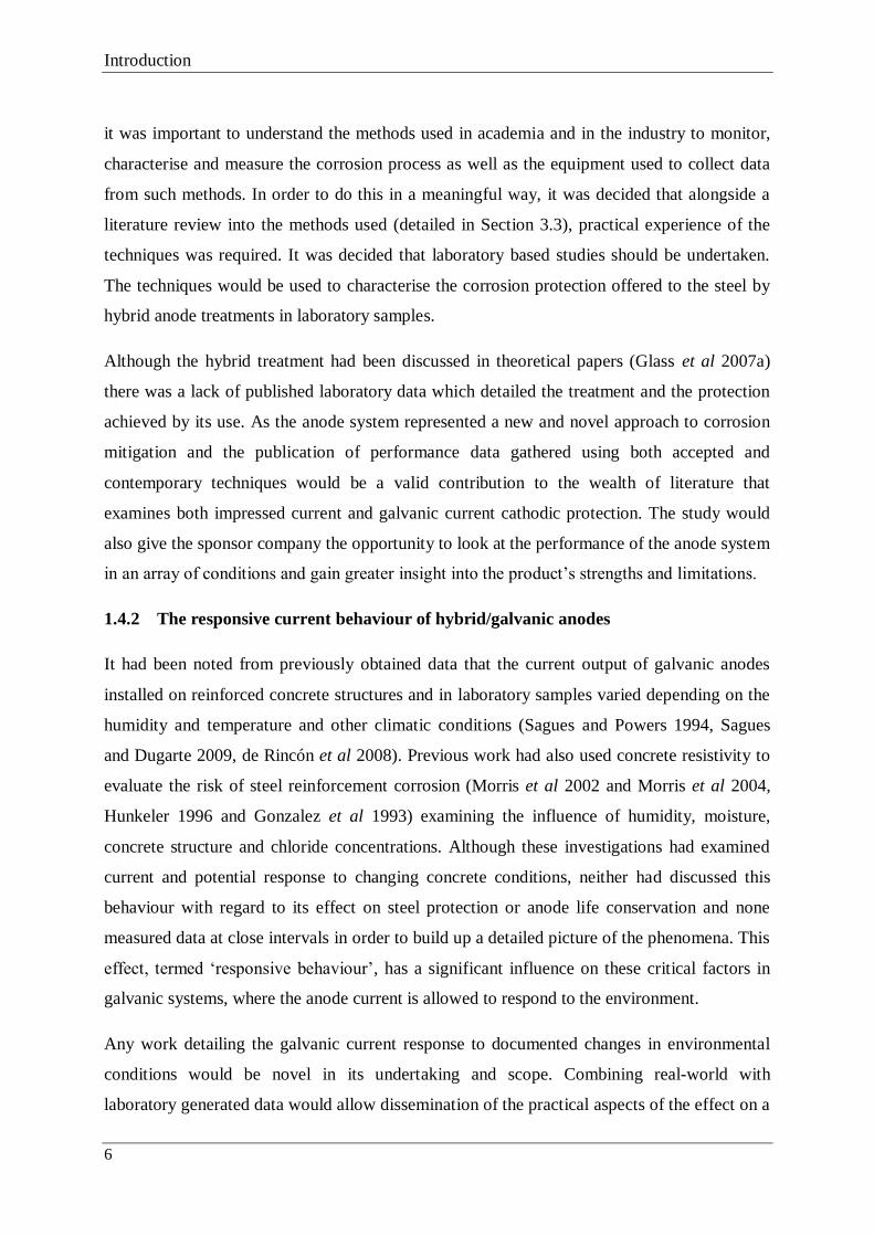
6
it was important to understand the methods used in academia and in the industry to monitor,
characterise and measure the corrosion process as well as the equipment used to collect data
from such methods. In order to do this in a meaningful way, it was decided that alongside a
literature review into the methods used (detailed in Section 3.3), practical experience of the
techniques was required. It was decided that laboratory based studies should be undertaken.
The techniques would be used to characterise the corrosion protection offered to the steel by
hybrid anode treatments in laboratory samples.
Although the hybrid treatment had been discussed in theoretical papers (Glass et al 2007a)
there was a lack of published laboratory data which detailed the treatment and the protection
achieved by its use. As the anode system represented a new and novel approach to corrosion
mitigation and the publication of performance data gathered using both accepted and
contemporary techniques would be a valid contribution to the wealth of literature that
examines both impressed current and galvanic current cathodic protection. The study would
also give the sponsor company the opportunity to look at the performance of the anode system
in an array of conditions and gain greater insight into the product’s strengths and limitations.
1.4.2 The responsive current behaviour of hybrid/galvanic anodes
It had been noted from previously obtained data that the current output of galvanic anodes
installed on reinforced concrete structures and in laboratory samples varied depending on the
humidity and temperature and other climatic conditions (Sagues and Powers 1994, Sagues
and Dugarte 2009, de Rincón et al 2008). Previous work had also used concrete resistivity to
evaluate the risk of steel reinforcement corrosion (Morris et al 2002 and Morris et al 2004,
Hunkeler 1996 and Gonzalez et al 1993) examining the influence of humidity, moisture,
concrete structure and chloride concentrations. Although these investigations had examined
current and potential response to changing concrete conditions, neither had discussed this
behaviour with regard to its effect on steel protection or anode life conservation and none
measured data at close intervals in order to build up a detailed picture of the phenomena. This
effect, termed ‘responsive behaviour’, has a significant influence on these critical factors in
galvanic systems, where the anode current is allowed to respond to the environment.
Any work detailing the galvanic current response to documented changes in environmental
conditions would be novel in its undertaking and scope. Combining real-world with
laboratory generated data would allow dissemination of the practical aspects of the effect on a

Introduction
7
concrete structure, whilst affording depth of analysis that would not be possible from real-
world data alone.
1.4.2.1 Steel protection criteria
Within the cathodic protection industry, there is an ongoing debate regarding the application
of protection criteria to steel in atmospherically exposed concrete and the basis of their
application. The pitting potential/re-passivation potential hypothesis (Section 2.2) forms the
basis of the theory that protection is based on achieving adequate steel polarisation, whereas
the pit re-alkalisation/pH maintenance hypothesis (Glass et al 2008, Roberts et al 2006, Glass
et al 2006) suggests that modifying the surface of the steel by raising the pH is the dominant
protective effect. The European standard (BS EN 12696 (2000) advocates the use of steel
polarisation criteria to determine whether a cathodic protection system is functioning
adequately.
Although widely applied, nominal steel polarisation criteria (discussed in Section 2.2.2) are
widely questioned and appear to be primarily used due to their practical simplicity and ease of
application. Galvanic cathodic protection systems sometimes fail to meet the polarisation
criteria although other techniques used to determine steel condition such as instantaneous
corrosion rate and de-polarised steel potential measurements suggest that the system is
adequately protecting the steel. As a result, the perceived need for polarisation may limit the
adoption of galvanic and hybrid cathodic protection systems which would otherwise provide a
satisfactory and cost-effective solution to reinforcement corrosion.
1.4.3 Commercially pure titanium degradation
The hybrid anode system consists of zinc anodes installed in the cover concrete using a
proprietary mortar. The anodes are then connected together using a commercially pure (CP)
titanium wire. Following the discovery of a small number of degraded areas of wire on site a
literature review identified a pitting risk to the wire due to the anodic polarisation. A research
project commenced aimed at characterising the conditions required for wire corrosion and
investigating the effect on the pitting potential of growing an oxide (using DC anodising) of
various different thicknesses (Section 4.10).
This section of the research was applied in nature, in that it aimed at solving a potential
problem that was specific to a material, product and set of conditions. It did not seek to add

Introduction
8
significant matter to ongoing academic debates regarding the mechanisms of the anodic
behaviour of titanium, but rather to identify the mechanisms causing the defects and
investigate methods to nullify or reduce their impact. Although the mechanism of pitting
corrosion of titanium is a well researched area (Dugdale and Cotton 1964, Posey and
Bohlmann 1967, Fattahi and Shariat 2008 and Sazou et al 2012), little effort has been
expended on analysing the effect of a grown oxide on the pitting potential in aggressive
electrolytes.
1.5 RESEARCH AIMS AND OBJECTIVES
The over-arching aim of the research was to investigate the practical and theoretical aspects of
a hybrid electrochemical treatment. In order to achieve this, the research has been split into
three distinct projects with their own aims and objectives. The background and justification
for these projects can be seen in Section 1.4 and the aims and objectives that relate to each
project can be seen in Table 1.1.

Introduction
9
Table 1.1 Research aims, objectives, selected methodology and outputs for the research
project undertaken
Research Aims Research Objectives Research methodology Research
Output
AIM 1
Characterise the
electrochemical
processes occurring in
hybrid anode
laboratory samples
using common industry
techniques
1. Gain greater understanding of steel
protection assessment methods
2. Apply assessment methods to the
testing of existing anode systems to
determine the effectiveness of the
cathodic protection offered
Literature review
Physical experimentation
Physical experimentation
Paper 1
Paper 1
AIM 2
Investigate the benefits
of the responsive
current behaviour of
cathodic protection
systems and discuss
with regards to existing
steel protection
hypotheses and criteria
3. Select and/or design samples and
experiments so that data is collected
from a range of concrete conditions
4. Investigate the relative effects of
environmental conditions on responsive
behaviour
5. Investigate the practical benefits of
responsive behaviour
6. Investigate responsive behaviour in
the context of current steel protection
hypotheses and criteria
Physical experimentation
Physical experimentation
Physical experimentation
Literature review
Physical experimentation
Paper 2
Paper 3
Paper 4
Paper 3
Paper 4
AIM 3
Investigate the causes
of the on-site
deterioration of
commercially pure
titanium feeder wire
and investigate
methods of protecting
against it
7. Identify the cause of surface
degradation seen on site
8. Identify a suitable process for
protecting commercially pure titanium
feeder wire against pitting corrosion
9. Assess any increased protection
offered
Literature review
Literature review
Physical experimentation
Physical experimentation

Introduction
10
1.6 LIST OF PUBLICATIONS
Table 1.2 presents the academic papers that were published as a result of the work presented
in this thesis.
Table 1.2 Journal and conference papers published as a result of the research undertaken
Ref. Journal/Conference
Title
Description
Ap
pen
dix
B
Pap
er 1
Journal: Materials and
Corrosion, 2011
Long term
assessment of a
hybrid
electrochemical
treatment
Presents the results of corrosion current
monitoring, corrosion rate measurement and
polarisation data taken from a chloride
contaminated concrete test block containing
a hybrid anode system over a 4.5 year period
Appen
dix
C
Pap
er 2
Conference:
CORROSION 2011,
Houston, Texas, USA
The Response of
Protective Current to
Environmental
Conditions
During Sacrificial
Anode Concrete
Repair Treatments
Presents analysis of data taken from hybrid
anode samples placed indoors/outdoors and
a single zinc/steel sample in the context of
responsive current behaviour and steel
protection hypotheses
Appen
dix
D
Pap
er 3
Journal: Corrosion,
Vol 67, 10, 2011
Response of
Protective Current to
Environmental
Conditions During
Sacrificial Anode
Concrete
Repair Treatments
A journal-edited version of Paper 2
Ap
pen
dix
E
Pap
er 4
Journal: Corrosion
Science, Vol 53
Responsive
behaviour of
galvanic anodes in
concrete and the
basis
for its utilisation
Discusses the response of zinc and steel
current to steel corrosion risk, the response
times of the different materials and the
utilisation of responsive behaviour in
relation to steel protection mechanisms

Introduction
11
1.7 THESIS STRUCTURE
The thesis is divided into five chapters:
Chapter 2 consists of a review of literature relevant to the research undertaken. This section
is referenced heavily in the discourse and forms part of the objectives presented in Table 1.1.
Chapter 3 presents the chosen research methodology and research methods used during the
research projects. The available methods are reviewed before the chosen methods are
presented and the reasons for their selection discussed.
Chapter 4 presents the research undertaken and the findings of the work carried out for each
task. This section refers heavily to the appended papers but provides a narrative to explain the
thought process behind the work.
Chapter 5 draws together the key findings and conclusions from the research undertaken and
discusses the impact of the research along with its limitations before suggesting future work.

Literature review
12

Literature review
13
CHAPTER 2 - LITERATURE REVIEW
This chapter aims to introduce the ways in which concrete influences the corrosion of steel
reinforcement, elucidate the theories surrounding steel corrosion protection in concrete and
discuss the ways in which the two predominant theories are validated. It also aims to present
and review previously published information on the mechanisms and processes involved in
the corrosion of titanium and protective anodising.
2.1 THE INFLUENCE OF LOCAL CONCRETE CONDITIONS ON
REINFORCEMENT CORROSION
The occurrence and/or rate of corrosion affecting reinforcement buried in concrete is
dependent on the nature of the concrete that surrounds it. The main influences are material
(mix design, compaction and cracking) and environmental factors (water availability,
temperature and chloride content), although the former will determine the influence of the
latter. The main influence of these factors is on the concrete’s resistance to current flow
between the anode and the cathode during corrosion activity (Bentur 1997, Bertolini et al
2004).
2.1.1 Material factors
Mix design – the ratios of water, OPC (ordinary portland cement) and aggregate will
determine the resistivity of the concrete near the surface of the steel due to the different
relative proportions of distinct materials each with a different characteristic resistivity. The
extent of hydration will also have an influence due to its influence on pore structure and
porosity. For example, low water to cement (w/c) ratio concretes have a low porosity due to
the filling of a high proportion of capillary pores with hydration products whereas high w/c
ratio concretes will not only have a much higher overall porosity volume, but many of the
capillary pores will be interconnected, increasing overall porosity. The addition of
admixtures such fly ash or ground granulated blast furnace slag or polymers to aid concrete
properties will also change the materials’ resistivity to current flow (Bentur et al 1997; Glass
and Buenfeld 2000).
Compaction - the degree of compaction achieved after pouring and working will also have an
influence on corrosion. Aerated voids reduce the resistivity of the bulk material by effectively
removing solid material and therefore resistance to current flow. Also, it has been noted that

Literature review
14
corrosion initiation tends to occur at the location of pore-solution filled voids at the steel
surface (Ann and Song, 2007).
Cracking - cracking due to low cover, poor placement, inappropriate mix design or
environmental factors can make buried reinforcement more susceptible to corrosion as it can
allow easy access to the steel from the surface (i.e., for chloride/moisture ingress) and reduce
the resistance to current flow between anodic and cathodic sites.
All of the above factors will also govern the pace of chloride ingress/carbonation and
therefore the time to corrosion initiation and its severity.
2.1.2 Environmental factors
Water availability – the availability of an ionic conductor will determine the quantity of
current that can flow between anodic and cathodic sites. Increasing water content will reduce
the resistivity of the concrete and increase the current that can flow. This is true except for
when the concrete approaches saturation and oxygen availability at the cathode limits current
flow (Broomfield 1997).
Temperature - the temperature of the pore water has a significant influence on the resistivity
of the concrete. This is due to the effect on ion mobility, ion-ion and ion-solid interactions
(Polder 2001). the higher the concrete temperature, the lower the resistance to ionic
movement will be.
Chloride content – although in itself an aggressive ion which propagates corrosion of steel in
concrete (see Section 2.4.1.1), the presence of chloride ions in the pore solution also has the
effect of increasing the concrete’s ionic conductivity and so increasing the corrosion rate once
a corrosion cell is established.
2.2 CORROSION PROTECTION OF STEEL IN CONCRETE
There is much debate regarding which treatment approach best addresses the dominant factor
affecting steel corrosion in concrete. It is argued that adequately cathodically polarising the
steel in order to suppress the steel corrosion reaction is the dominant protective effect. This is
supported by the pitting potential/re-passivation potential hypothesis (BS EN 12696 (2000)).
Others have suggested that reinstating the alkaline environment at acidic pitting sites is the
dominant protective effect, with reports that typical ICCP current densities are enough to halt

Literature review
15
corrosion in this manner when applied for long periods (Glass et al 2008, Christodoulou et al
2010), or delay its onset in aggressive environments once the protective current has been
removed (Presuel-Moreno 2002, Glass et al 2007c). These observations support the basis of
the pit re-alkalisation/pH maintenance hypothesis (Glass et al 2007a, Glass et al 2006).
In this section the background theory behind these two hypotheses is presented and the
protection criteria affiliated with eachare discussed.
2.3 PITTING POTENTIAL/RE-PASSIVATION POTENTIAL THEORY AS A
BASIS FOR PROTECTION
Diagrams like those shown in Figure 2.1 can be used to study the corrosion behaviour of
metals. The potential of the metal in a given electrolyte (E) is plotted against the logarithm of
the current (Log ia). Where the curve generated from the anodic reaction intercepts the y axis
it is said that the metal is immune from corrosion. Where the anodic and cathodic reaction
curves meet we obtain the corrosion potential Ecorr and the corrosion rate ia. The anodic and
cathodic reactions for iron corrosion are given by Equations 2.1 and 2.2.
Fe → Fe2+
+ 2e- (Anodic) (2.1)
½O2 + H2O + 2e- → 2OH
- (Cathodic) (2.2)
If the potential of metal in an electrolyte (E) is lower than the equilibrium potential for the
oxidation process (Eeq) then corrosion cannot occur. This is the ‘immunity’ condition and can
be used to describe the condition of steel in healthy, high pH concrete (Pedeferri 1996).
Corrosion of the metal can occur if E > Eeq. E depends on the metal and the electrolyte but
will increase when there is an anodic current and decrease when there is a cathodic current.
Eeq is given by Nernst’s equation (Equation 2.3).
2log2
3.20
Feeq aF
RTEE (2.3)
where E0 is the standard potential, R is the universal gas constant, T is the absolute
temperature, F is Faraday’s constant and α is the ion concentration of the electrolyte.
In carbonated concrete the corrosion rate (given by the anodic current ia) increases with the
corrosion potential (E) (Figure 2.1(a)) (Glass et al 1991). Steel in alkaline environments

Literature review
16
(Figure 2.1(b)) displays ‘active-passive’ behaviour which describes a process whereby ia
initially increases above Eeq as the corrosion potential increases (active zone) then decreases
to very small values due to the formation of a passive oxide film (passive zone). At high
potentials, the oxide film breaks down and ia increases again.
Figure 2.1 a) ‘Active’ and b) ‘Active-passive’ anodic behaviour of metals, showing active
and passive regions (after Pedeferri 1996)
When metals are placed in aggressive environments their corrosion potential (Ecorr) is higher
than Eeq. The difference between these two potentials is the driving voltage (ΔE) which, when
divided by the anodic resistance (R), gives the corrosion rate ia (Equation 2.4):
ia = ΔE/R (2.4)
Based on this model, a method must be employed to push the E to values equal to or below
Eeq, making ΔE and therefore ia very small. This however is only appropriate for steel
immersed in seawater or soil. The aim when cathodically protecting atmospherically exposed
concrete is not to polarise the steel to Eeq but to a potential where a passivity condition can be
maintained for a wide range of atmospheric conditions (Ecorr to Ep and therefore icorr to ip in
Figure 2.2). The polarisation required is much less than that required to achieve Eeq which
carries the risk of over-protection and hydrogen generation at the cathode when the potential
is driven below Eeq,H, the equilibrium potential for hydrogen. Eeq,H is pH dependent but is -
950 mV at pH >12.5 (Pedeferri 1996). Pushing the steel potential lower than Eeq,H can result
in hydrogen embrittlement which can have structural implications.
a) b)

Literature review
17
Figure 2.2 Method of achieving cathodic protection in atmospherically exposed concrete
As a polarising current must be applied to achieve protection, cathodic protection systems
permanently cathodically polarise the steel in order to maintain a negligibly low corrosion
rate.
2.3.1 Protection Criteria
In recent years, there has been an increasing demand from the industry for standard test
methods to apply to the corrosion testing and monitoring of steel reinforced structures. Using
the theoretical basis discussed above it is postulated that corrosion protection will be achieved
if one of the following factors is satisfied (BS EN 12696 (2000)):
o An ‘instant off’* steel potential (potential corrected for IR drop) more negative than -
720 mV with respect to Ag/AgCl/0.5 KCl reference electrode
o A potential decay of 100 mV over a maximum of 24 hours (minus IR drop)
o A potential decay over an extended period of at least 150 mV from the ‘instant off’
potential
Eeq
E
Log ia
Ecorr
ip icorr
Ep
Anodic
reaction
Cathodic
reaction

Literature review
18
* potential of the steel immediately after it is disconnected from the anode system.
By far the most commonly used criterion for steel in concrete is that of the 100 mV potential
decay. The accepted basis for its use is that a 100 mV shift in the corrosion potential Ecorr is
sufficient to induce an order of magnitude reduction in corrosion rate. The European Standard
relating (BS EN 12696 (2000)) states that the criteria are “not necessarily supported by
theoretical considerations, but are a non-exhaustive, practical series of criteria to indicate
adequate polarisation which will lead to the maintenance or re-establishment of protective
conditions for the steel within the concrete.
2.3.2 European Standard BS EN 12696 (2000)
The European Standard BS EN 12696 (2000) aims to specify the performance requirements
for cathodic protection of steel in atmospherically exposed concrete, and is based on the
concept of adequate polarisation. The standard includes a diagram (Figure 2.3) of steel
potential vs. concrete chloride content, which is used to explain the method of evaluating
structures and achieving corrosion arrest depending on the aims of the treatments. It is divided
into distinct zones:
When the steel potential and concrete chloride content is in;
Zone A - Pitting initiates and propagates
Zone B - Pitting does (will) not initiate but can propagate
Zone C - Pitting does (will) not initiate nor propagate
Zone D - Hydrogen embrittlement risk to high strength steels
Zone E - Reduction of the steel/concrete bond.
The aim of cathodic protection in atmospherically exposed concrete is to polarise the steel
into Zone D for normal low strength steel or into Zone C for high strength steels. This means
that if sufficient (>100 mV) depolarisation is realised; the steel potential will sit in Zone C or
the lower section of Zone B.
The standard suggests that the treatment paths for the different methodologies proceed as
follows:

Literature review
19
Cathodic Prevention 1 → 2 → 3
Cathodic Protection restoring passivity 1 → 4 → 5
Cathodic Protection reducing corrosion rate 1 → 4 → 6
In the case of cathodic prevention, the steel is polarised from the start of structural service life
(1→2) when there is zero chloride content, in order to increase the critical chloride threshold
required for corrosion to occur. As the chloride content increases (3), the polarisation is
maintained. In both cathodic protection methodologies, the steel is polarised when there is a
certain chloride content in contact with the steel (4), usually after considerable structure
service life.
Figure 2.3 Schematic illustration of evaluation paths of potential and chloride content on steel
reinforcement during service life (BS EN 12696 (2000))
2.3.2.1 Critique of BS EN 12696:2000
ASTM C876 – 09 (1999) states that if an Ecorr more negative than -350 mV vs. Cu/CuSO4
(copper –copper sulphate reference electrode) is found during a potential survey of cover
concrete, there is a 90% chance of reinforcement corrosion. Potentials more positive than -
200 mV vs. Cu/CuSO4 indicate a 90% chance of negligible corrosion. Bridge Advice 35
(1990) suggests that any concrete covering steel with a potential more negative than -350 mV
Stee
l po
ten
tial
(mV
) vs.
Ag/
AgC
l
% Chloride content by weight of cement
Epit
Eprot
Ste
el p
ote
nti
al (
mV
) vs.
Ag
/AgC
l

Literature review
20
vs. Cu/CuSO4 and containing more than 0.3% chloride by weight of cement should be
removed if no electrochemical treatment is to be used as it represents a very high corrosion
risk. However, for corrosion to occur at -350 mV vs. Cu/CuSO4 using the model in Figure 2.3
the chloride content of the concrete would have to be >1.7 % by weight of cement. The
schematic also suggests that an Ecorr of -100 mV vs. Ag/AgCl (-20 mV vs. Cu/CuSO4) and a
chloride content of 0.8% indicates that pitting will initiate and propagate. Experience suggests
that very few engineers undertaking potential surveys would consider these figures to suggest
corroding reinforcement.
The model does not take into account any acknowledged effects (Pedeferri 1996) such as re-
alkalisation or chloride extraction, which have been observed to make Ecorr more positive
when applied for long periods and hence reducing the magnitude of polarisation required.
Also, the standard does not account for the changes in the need for protective
current/polarisation brought about by changes in the corrosion risk to the steel (Paper 4,
Appendix E).
2.4 PIT RE-ALKALSIATION AND pH MAINTENANCE AS A BASIS FOR
PROTECTION
Steel cast into healthy concrete will not corrode due to the high pH of the cement paste at the
steel surface due to the growth of a stable oxide layer (Broomfield 1997). It is acidification of
the steel which leads to passive layer damage and the initiation of corrosion. As discussed in
Section 2.2, one way to halt or dramatically reduce corrosion is to apply a cathodic current to
cathodically polarise the corrosion reaction.
Cathodic polarisation of steel in concrete leads to a rise in the pH at the steel/concrete
interface (Pedeferri 1996, Broomfield 1997). This is because oxygen reduction at the steel
during the corrosion process generates hydroxyl ions. A galvanic or impressed current leads
to a significant increase in the amount of hydroxide being produced as this is proportional to
the applied charge.
Until recently, like chloride removal in the applied electrical field, pH increase has been
considered as a beneficial secondary effect of applied cathodic protection current densities
when being used to treat steel suffering from chloride-induced corrosion. However, the
concept of re-alkalisation is well established in the treatment of carbonation-induced
reinforcement corrosion (Section 2.3.1.2).

Literature review
21
2.4.1 Acidification of the steel surface
In order to investigate the protective effect of re-alkalisation with regards to corrosion
mitigation, it is important to understand the mechanism of acidification and the resulting
corrosion propagation at the steel surface.
2.4.1.1 Chloride induced corrosion
When chloride ions (Cl-) are present in concrete local to the steel, a potential difference
attracts them to the anodic sites. A local fall in pH arises from the hydrolysis of dissolving
iron ions. Dissolving iron reacts with water to form iron hydroxides and hydrogen ions. The
positively charged hydrogen ions are balanced by the presence of negatively charge chloride
ions producing hydrochloric acid (Figure 2.4).
Figure 2.4 The classical corrosion model of pitting attack, after Broomfield (1997)
It is the competing processes of HCl and OH- production at the steel surface that will control
whether corrosion will propagate or re-passivation will occur. A continuous supply of
chloride ions is required to sustain corrosion.
2.4.1.2 Carbonation
Carbonation is caused by the penetration of atmospheric CO2 molecules into the concrete and
their reactions with calcium hydroxide, C-S-H gel and with the alkali and calcium ions in the
pore solution. The effect of these reactions is the reduction in pH of the concrete and the onset

Literature review
22
of general corrosion. Calcium hydroxide (Ca(OH)2) is the hydrate in the cement paste that
reacts most readily with CO2:
CO2 + H2O → H2CO3 (Carbonic acid) (2.5)
H2CO3 + Ca(OH)2 → CaCO3 + 2H2O (2.6)
Locally available calcium hydroxide is consumed (Equation 2.6), precipitating calcium
carbonate and allowing the pH to fall to values approaching neutrality (pH 7) (Bertolini et al
2004). A carbonation front then proceeds into the concrete. The speed with which it
progresses will depend on factors including CO2 concentration, humidity, temperature and
concrete mix design (Bentur et al 1997, Broomfield 1997).
2.4.2 The thermodynamic basis for re-alkalisation
Pourbaix (1974 and 1974(a)) acknowledged that the corrosion of metals is not only
determined by their potential, but also by the pH of the solution surrounding them. He
produced thermodynamic stability diagrams of metals in different media. A modified version
of the potential – pH diagram for iron in water is shown in Figure 2.5.
Figure 2.5 Potential – pH equilibrium diagram for the H2O – Fe system at 25ºC (adapted
from Pourbaix 1974).
a
b

Literature review
23
The high pH of the concrete (~pH 12-13) means that steel reinforcement sits in the ‘passive’
zone on the equilibrium diagram with the passive ferric oxides being the most stable form of
iron. In this environment, iron remains passive over a wide range of potentials. For steel to
corrode, the pH must drop significantly so that the steel moves into the ‘corroding’ zone of
the diagram ((a) to (b) in Figure 2.5). This is often accompanied by a drop in the steel
corrosion potential.
To achieve re-passivation of corroding steel in an aqueous environment, the pH must be
increased with the generation of hydroxyl ions exceeding the concentration of chloride ions.
Glass and Buenfeld (1995b) illustrated that a certain ratio of OH- to Cl
- concentration must be
realised to achieve re-passivation. This theory underpins the pit re-alkalisation concept which
suggests that rather than being achieved by polarisation and a negative potential shift (Figure
2.3), the primary protective effect is achieved by increasing the pH at corroding sites, i.e., by
generation of hydroxide. With reference to Figure 2.5, this would mean moving the steel from
(b) to (a). The amount of hydroxide generated is proportional to the amount of charge passed
to the steel by the cathodic current and so it is logical that high current treatments affect more
change at the steel surface.
The pH maintenance part of the theory pertains to maintaining a favourable ratio of Cl- to OH
-
ions following the treatment. Once the high current treatment has been applied, there will be a
sufficient concentration of OH- at the surface of the steel to maintain passivation in the short
term. However, if for example, chlorides are still able to penetrate the concrete to the level of
the steel, it is probable that corrosion could be re-established in future as OH- ions are
consumed and more Cl- ions collect at the steel surface. A comparatively low current can be
applied to maintain the generation of OH- and attraction of Cl
- ions to the anode, therefore
maintaining the protective ratio described above (Glass et al 2008). It has been suggested that
OH- ions combine with corrosion products and Ca
+, K
+ and Na
+ drawn to the cathode during
impressed current treatments to form alkali rich solid phase inhibitors at the steel/concrete
interface (Glass and Chadwick 1994, Glass et al2008 and Glass et al 2007c). Separate studies
have noted the presence of suspected calcium hydroxide, calcium-aluminium-rich phases
(Marcotte et al 1999 and Glass and Buenfeld 2000), sodium rich phases and Friedel’s salt
(Orellan et al 2004) at the interface.

Literature review
24
2.4.3 Evidence of the protective effect
It has been reported that cathodic protection current densities are enough to halt corrosion
when applied for long periods, or delay its onset in aggressive environments once the applied
current has been removed. Christodoulou et al (2010) found that 2 years after a 20-year old
ICCP system on the Midland Links Viaducts, UK, had been switched off, corrosion had not
re-initiated. This was in spite of a measured >1% chloride content by weight of cement
measured at the steel in 60% of the test locations. Similarly, Presuel-Moreno et al (2010)
noted the persistent effect that an ICCP system had on the steel once the polarising current
had been removed, reporting that a significant number of test locations remained passive up
until the work ended at 220 days. This was in spite of a relatively low impressed current (5
mA/m2) applied to the steel for 9 years and very high concrete chloride contents. These
studies and observations have lead to the development of the pit re-alkalisation/pH
maintenance hypothesis (Glass et al 2007a, Glass et al 2007b and Glass et al 2008) which
argues that making the environment at the steel less aggressive is the dominant factor in
protecting atmospherically exposed steel in concrete.
2.5 ACCEPTANCE CRITERIA
Rather than basing cathodic protection system performance on the potential shift affected by
the installed anodes, the ability of re-alkalisation to halt steel corrosion can be assessed by
several different methods, including steel corrosion rate and potential measurements. These
methods are discussed in Chapter 3 (Sections 3.3 and 3.4), however indicative methods are
discussed below.
2.5.1 Indicative measurements of re-alkalisation/re-passivation
As well as quantitative methods such as those described in Chapter 3, there are several
techniques that can be used to indicate the effectiveness of an electrochemical treatment
applied to steel reinforcement.
2.5.1.1 Depolarised steel potential
If steel potential data can be obtained prior to the applied process, and then again following a
period of treatment, a comparison of the results can give a good indication of how the
treatment has modified environment at the surface of the steel (Section 4.3). Steel potentials
of <-350 mV vs. Cu/CuSO4 generally indicate the presence of steel corrosion, with potentials

Literature review
25
of >-200 mV indicating a low risk of corrosion (ASTM C876-09 1999). It follows then that a
significant positive shift in steel potential in reinforced concrete under similar conditions
would indicate the re-passivating effects of re-alkalisation.
Figure 2.6 shows the distribution of steel potentials taken from embedded reference electrodes
on the Tay Road Bridge, Scotland (Glass 1996). Cathodic protection was applied for 12
months and then the system was switched off. It can be seen that the de-polarised steel
potentials at these areas of high corrosion risk were all shifted to more positive values. In one
case the positive potential shift was at least 150 mV.
Steel potential readings are only ever indicative in nature due to the effect that environmental
factors have on the recorded results. Temperature, concrete moisture content and the quality
of the interface between the reference cell and the concrete will all affect the data collected;
however, the effect of these factors will be in the range of tens of millivolts. Large changes in
steel potential in similar environmental conditions indicate changes in the steel corrosion
process.

Literature review
26
Figure 2.6 Distribution of measured steel potentials recorded over a one-year period on the
Tay Road Bridge, Scotland (Glass 1996)
2.5.1.2 Concrete pH measurements
To assess the effect of re-alkalisation directly, small sections of the steel can be broken out
and after loose material has been removed, sprayed with an indicator solution (typically
phenolphthalein). Healthy concrete has a pH of 12-13 and will turn the indicator a pink
colour. Carbonated concrete or acidic areas close to the steel will cause no change in the
indicator colour (Pacheco Torgal 2012).
Figure 2.7 shows a section through a temporarily installed sponge anode and carbonated
reinforced concrete beam after it had been treated with a short term high current
electrochemical treatment. A universal indicator was applied to the anode and the surface
from where the steel had been removed. The red colour at the anode indicates a pH less than
2, while the purple colour at the steel indicates a pH greater than 9 (Tong et al 2012).
Potential (mV vs Ag/AgCl)
Num
ber
of
Rea
din
gs
0
10
20
-35
0
-32
5
-30
0
-27
5
-25
0
-22
5
-20
0
-17
5
-15
0
-12
5
-10
0
-75
-50
-25 0
0
10
20
0
10
20
30
0
10
20
30
40
Mean = -185 mV (Ag/AgCl)
Std. Dev. = 61 mV
Mean = -178 mV (Ag/AgCl)
Std. Dev. = 60 mV
Mean = -153 mV (Ag/AgCl)
Std. Dev. = 58 mV
Mean = -106 mV (Ag/AgCl)
Std. Dev. = 43 mV
(a) Initial corrosion
potentials
(b) After 1 month
(c) After 3 months
(d) After 12 months

Literature review
27
Figure 2.7 A section through an anode and carbonated reinforced concrete beam after it had
been treated with a high current short-term electrochemical treatment (Drewett 1999)
2.5.2 Corrosion rate measurements
Rather than using polarisation criteria alone to determine that the anode system is sufficiently
protecting the steel (as discussed in Section 2.2.2), measurement techniques such as those that
will be described in Sections 3.4.3 and 3.4.4 can be used to obtain instantaneous corrosion
rate measurements.
2.6 SUMMARY
The pitting potential/re-passivation potential theory is a well-established basis for the
protection criteria applied to cathodic protection installations based on polarisation. The
theory that the European Standard is based on has flaws, which may affect the way that
reinforcement corrosion is assessed on site.
The postulated protective effect using the pit re-alkalisation/pH maintenance methodology
relies on making the environment at the steel less aggressive and is proportional to the amount
of current passed. Although there is no standard measurement to measure protection, steel
corrosion rate and potential measurements are convenient ways of assessing the condition of
the reinforcement.
Void left by steel
Temporary sponge anode

Literature review
28
2.7 TITANIUM PITTING IN THE PRESENCE OF HALIDES
The highly corrosion resistant qualities of titanium are a result of the oxide layer that forms on
the metal surface when it is exposed to air or water. Its structure is nominally TiO2 (Equation
2.7) although the crystal structure, orientation and defect density strongly depend upon the
conditions of film growth.
Ti + O2 → TiO2 (2.7)
Breakdown of the oxide layer results in the exposure of the underlying titanium metal which
can result in pitting corrosion (Donachie 1988).
Pitting is an aggressive form of localised corrosion, which results in accelerated dissolution of
the underlying metal usually due to a breakdown in a protective passive film. For pitting to
occur, an aggressive ion species must be present; chloride is the most common of these.
Pitting is considered to be autocatalytic in nature; as the pit grows the local conditions alter to
promote further pit growth. The anodic and cathodic areas separate during pitting with the
anodic areas becoming depleted in cathodic reactant (typically oxygen), shifting the cathodic
reaction outside of the pit where oxygen is more freely available. The pit cavity becomes
enriched with metal cations, which results in an increase in concentration of anionic species
(chloride) in the pit to maintain charge neutrality. The pH in the pit falls due to cation
hydrolysis (Equation 2.8):
Me2+
+ 2H2O → Me(OH)+ + H
- + H2O → Me(OH)2 + 2H
+ (2.8)
In contrast, the cathodic reactions lead to an increase in pH at cathodic locations due to
oxygen reduction. Acidic, chloride rich environments are aggressive to most metals, including
steel and titanium. Figure 2.8 describes the autocatalytic processes occurring during pitting of
a metal in aerated NaCl solution (ASM International 2003):

Literature review
29
Figure 2.8 The autocatalytic processes occurring in a pit propagating in an aerated NaCl
solution (ASM International 2003)
Breakdown will occur at the weakest part of the oxide layer, such as grain boundaries, surface
imperfections or an area of thin oxide meaning that pitting sites on the metal surface often
appear to be random. Titanium does not normally pit in chloride containing media, however if
it is anodically polarised and the driving voltage is sufficient, rapid pitting can occur. Pit
initiation is associated with a range of potentials depending on the conditions (solution
concentration, temperature, agitation level). Several authors have set this pitting potential at 9
- 14 volts in chloride solutions at 20-25°C, (Hackerman and Hall and Rudiger and Fischer
(cited in Dugdale and Cotton 1964), Dugdale and Cotton 1964, Trompette et al 2011, Basame
and White 2000, and Posey and Bohlmann 1967. A polarisation experiment illustrating the
breakdown of titanium in molar KCl can be seen in Figure 2.9.

Literature review
30
Figure 2.9 A cell voltage/Log current polarisation curve for the oxidation of titanium in
molar KCl (Dugdale and Cotton 1964)
2.8 TITANIUM ANODISING
Anodising is a process whereby a protective oxide layer is intentionally grown on a metal by
electrolytic means. After suitable pre-treatments to remove the native oxide the component is
placed in an electrolytic cell with a suitable cathodic counter electrode before a DC current is
applied at a desired voltage. The applied voltage determines the thickness of the oxide layer
and due to interference effects, the colour of the anodised article.
The aim of anodising processes is to grow the oxide film in such a way as to display the best
properties possible for a given application. Stringent control of the process parameters allows
the design of application-specific oxide structures, which can be critical to the function of the
finished article.
2.8.1 Film Formation
Anodic oxidation describes the electrode reactions along with electric field driven metal and
oxygen ion diffusion, which leads to the formation of an oxide film on the anode surface. The
structural and chemical properties of the layer vary widely depending on the process
parameters, including anodising voltage and current, electrolyte composition (strength and

Literature review
31
solution composition), temperature and applied current, pH, and treatment duration. Anodic
oxides on titanium are especially sensitive to changes in any of these parameters and even if
great care is taken to ensure the same conditions for each part, significant differences can
sometimes be seen (Aladjem 1973).
The main reactions leading to oxide growth are described in Equations 2.9 to 2.12:
At the Ti/Ti oxide interface:
Ti ↔ Ti2+
+ 2e- (2.9)
At the Ti oxide/electrolyte interface:
2H2O ↔ 2O2-
+ 4H+ (oxygen ions react with Ti to form oxide) (2.10)
2H2O ↔ O2 (gas) + 4H+ + 4e
- (O2 gas evolves or stays on electrode surface) (2.11)
At both interfaces:
Ti2+
+ 2O
2- ↔ TiO2 + 2e
- (2.12)
The titanium and oxygen ions formed in these redox reactions are driven through the oxide by
the applied electric field, resulting in the formation of the oxide film. Due to its resistance, the
applied voltage drop occurs mainly across the oxide, however, as long as the electric field is
high enough to drive ions through the oxide, a current will flow and the oxide will continue to
grow. It has been found that the final oxide thickness is almost linearly dependent on the
applied voltage (Equation 2.13):
d = αU (2.13)
where d is the oxide thickness, U is the applied voltage and α is a constant, usually between
1.5–3 nm V-1
. Above a certain voltage, the oxide that has grown will no longer be resistive
enough to prevent current flow and it will break down. This leads to increased oxygen
evolution and frequently sparking. The result of so called ‘spark-anodising’ is usually an
amorphous and porous layer (Aladjem 1973).
Some authors found that film growth/structure is time dependent, with the length of time in
the electrolyte and under the applied current resulting in different thicknesses and
topographies (Figure 2.10) (Kennedy et al 1983, Aladjem 1973).

Literature review
32
a)
b)
c)
Figure 2.10 SEM micrographs of Ti-6Al-4V anodised at 10V in 5M NaOH solutions at 20°C
for a) 10 minutes; b) 20 minutes and c) 30 minutes (taken from Kennedy et al 1983)
2.8.2 Film Composition
The thickness of the natural oxide layer ranges from 5 to 70 Å. This thickness will depend on
the metal composition, surrounding medium and heat treatments during working. The
composition of the layer has been studied and debated by many researchers, with workers
reporting that it consists of TiO2 in its rutile, anatase and lower amorphous crystal form
(Pouilleau et al 1997). It is likely that they are all correct and that the form is reliant on the
conditions under which the investigations were carried out. Alloying additions and metal
purity will also have a bearing on the structure, with a TiAl6 alloy incorporating amorphous
Al2O3 as well as TiO2 (Pouilleau et al 1997).
2.8.3 Oxide Morphology
Depending on the anodising parameters and solution used, the morphology of the oxide
formed on titanium is variable. Compact, ordered ‘honeycomb’ structures can be formed in
chromic /hydrofluoric acid solutions and oxides having the appearance of a painted coating
can be formed using sodium hydroxide (NaOH) solutions (Figure 2.11). This allows the
‘design’ of processes which can produce anodised surfaces to suit specific applications.

Literature review
33
Figure 2.11 a) Porous microstructure of anodic oxide grown on TiAl6 in chromic
acid/hydrofluoric acid solution at 5V (Zwilling et al1999), and b) in 0.1 Molar NaOH
solution at 16V
2.8.4 Surface preparation prior to anodising
The aim of the surface preparation is to provide a clean, ordered native oxide surface, which
will form the basis for the oxide growth.
The first stage of the process is to remove grease and oil from the surface (Donachie 1988).
Following this, the pre-treated oxide layer may still be coarse and non-uniform, requiring
further treatment to achieve a uniform base for oxide growth. A general treatment may
include an oxide removal treatment (pickle) for 1-5 minutes in a solution composed of 15-30
wt% nitric acid and 1-2 wt% hydrofluoric acid between 20 and 60°C. An effective pickle for
both the titanium is 33.2% nitric to 1.6% hydrofluoric acid. (Donachie 1988 and Liu et al
2004). Distilled water rinses are employed between the treatment stages.
The hydrofluoric acid in the solution readily attacks the TiO2 and reacts with the underlying
Ti to form soluble titanium fluorides and hydrogen. It is thought that a ratio of 10:1 (Cigada et
al 1992) to 15:1 nitric to hydrofluoric acid can minimise the formation of free hydrogen and
therefore reduce embrittlement of the surface layer (Liu et al 2004).
2.8.5 The anodising process
Although industrial anodising processes are proprietary in nature, a general process involves
the pre-treatments detailed above, followed by immersion in an agitated anodising solution
b) a)

Literature review
34
using a suitable rig to ensure electrical connectivity. Following the anodising procedure, the
article will be removed from the bath and rinsed to remove any remaining solution.
2.8.6 Anodising solutions
Although any liquid containing ionic species can be used to anodise titanium, electrolytic
anodising falls into two broad categories; acid and alkaline. A typical formulation for acid
anodising may consist of 80% phosphoric acid, 10% sulphuric acid and 10% water, although
each of these acids can be used alone. Acid anodising is widely used for aesthetic applications
such as jewellery and automotive parts due to the wide array of colours that can be produced
(Donachie 1988 and Titanium Information Group 2004).
Alkaline anodising processes are generally used when wear resistance/anti-galling surfaces
are required (such as in threaded components), with typical electrolyte baths being based on
sodium hydroxide (Kennedy et al 1983), and hydrogen peroxide (Takeuchi et al 2003).
Alkaline processes can also be used for decorative purposes, often utilising a bath consisting
of 3-5% tri-sodium phosphate in distilled water (Titanium Information Group 2004).
2.8.7 The protective effect of anodising
Although many authors suggest that anodising increases the corrosion protection offered to
the titanium substrate, little work has been carried out to quantify the effect that a grown
oxide has on corrosion resistance. Casillas et al (1994) reported that the thickness of thin
oxide layers was proportional to the pitting potential in 1M KBr solution although no tests
have been completed for thicker grown oxides. Afshar and Vaezi (2003) found that the
corrosion rate of titanium in phosphate buffered saline solution was reduced dramatically
when the substrate was anodised in NaOH at 25-35V. These were both solution experiments
under anodic polarisation.
2.9 SUMMARY
The main findings of this section of the literature review were:
o The breakdown potential of the native titanium oxide is between 8 and 14 volts in
chloride solution depending on the experimental conditions.
o Assuming identical exposure conditions, precursor sites for pitting are impossible to
predict without lab-based equipment.

Literature review
35
o Surface preparation is key to achieving a consistent grown oxide.
o Solution strength and anodising duration will affect the morphology of the oxide layer.
o It has been observed that oxide layer thickness is proportional to breakdown potential
in certain electrolytes.

Research Methodology
36

Research Methodology
37
CHAPTER 3 - RESEARCH METHODOLOGY
This section will introduce the research methodology that has been adopted during the
investigations and briefly introduce potential investigatory techniques. Finally, the chosen
research techniques will be discussed in more detail and their use justified in the context of
the research.
3.1 RESEARCH METHODOLOGIES
Research methodologies broadly fall into one of two categories; quantitative or qualitative.
The choice of methodology depends on the intended outcome of the research undertaken
(Fellows and Liu 1999).
Quantitative research is a means for testing objective theories or hypotheses by examining the
relationship between variables. These variables, in turn, can be measured, typically using
instruments, so that numerical data can be obtained and analysed (Cresswell 2009). Scientific
research tends to be quantitative in nature.
Qualitative research is subjective in nature and was developed within the research field of the
social sciences. Techniques include surveys, questionnaires, case studies and FEM modelling.
Control over behavioural aspects of the test subjects is generally absent (Naoum 2007).
In order to decide which type of research method to use for the research it was necessary to
break down the research project into a series of aims and objectives with their expected
outputs. The table produced by this exercise can be seen in Section 1.5.
3.2 CHOSEN RESEARCH METHODOLOGIES
Aim 1 required an investigation into the electrochemical effects caused by an applied
electrochemical treatment, Aim 2 required the acquisition of environmental data to relate to
electrochemical phenomena and Aim 3 required investigation into the intrinsic properties of a
specific material. Most of the objectives required analysis of numerical data measured by
suitable equipment or relied on reviewing previous analysis of such data. As a result, the
nature of the Aims made it impossible to carry out the objectives using anything other than
quantitative methods and physical experimentation.

Research Methodology
38
Due to the scientific nature of the research the two methodologies selected to achieve Aims 1
to 3 were literature review and physical experimentation.
3.2.1 Literature review
Literature reviews were carried out at various stages of the research project as demanded by
the aims and objectives (Chapter 2). The review process ranged from investigations into the
correct application and interpretation of experimental techniques (Aim 1) to the development
of corrosion protection criteria (Aim 2) and the analysis of titanium deterioration seen on an
installation site (Aim 3).
The aim of the literature review in all cases was to focus the research and ensure the
relevance, novelty and validity of the work being undertaken in order to build upon and
expand upon existing knowledge.
3.2.2 Physical experimentation
Physical experimentation represents models, or investigates physical phenomena (Holt 1998).
Experiments may be performed in the field (e.g., in situ anode system performance), or in the
laboratory under more controlled conditions. Often these two techniques are combined to
allow comparison of data and give a more complete picture of the performance of the
phenomenon being tested. Typically, laboratory-based tests are carried out in an environment
where result-influencing factors are more tightly controlled, whereas field tests generally
represent true-to-life test conditions where variables are less controllable but closer to real
operating conditions (Holt 1998).
3.2.2.1 Research technique considerations
‘Research technique’ pertains to the specific investigatory technique used in the research
(Naoum 2007). Engineering measurements should be taken using suitable test methods and
devices that take into account the key research issues and variables related to the object under
investigation (EAL 1997). In order to ensure the applicability of the test, the following factors
require consideration during test design:
Repeatability – Closeness of the agreement between the results of successive measurements
of the same measurand carried out under the same conditions of measurement.

Research Methodology
39
Reproducibility – Closeness of the agreement between the results of measurements of the
same measurand carried out under changed conditions of measurement.
Uncertainty (of measurement) – The parameter related to the results of a measurement that
characterises the dispersion of the values, for example, a standard deviation. Uncertainty
represents the summation of all the factors which affect the recorded measurement (EAL
1997).
In summary, the tests used to collect the required experimental data must be carefully carried
out in order to ensure that the above conditions are satisfied. Consideration must be given to;
Test specimen manufacture
Suitability of test method
Suitability of testing equipment
Calibration of testing equipment
Environmental conditions of test areas
Physical experimentation was used in the investigation of Aims 1-3 and in order to achieve
the majority of objectives detailed in Table 3.1. The details of the specific experiments used
can be found in Chapter 4 and in the appended Papers (Appendices B-E).
3.3 AVAILABLE RESEARCH TECHNIQUES
There are numerous electrochemical techniques available to assess and monitor the corrosion
condition of metals which use a variety of methodologies and theoretical bases. A summary
of the more commonly used methods can be found in Song and Saraswathy (2007), Andrade
et al (2004), Andrade and Alonso (1996) and Sagues (1993).
All of the quantitative techniques aim to determine the polarisation resistance (Rp) which can
then be used to calculate the corrosion rate (iCORR)
This section presents a short summary of the theory and practice behind some of the available
techniques for characterising corrosion phenomena both on site and in the laboratory.
3.3.1 Galvanostatic pulse technique
The technique involves the passing of a short galvanostatic anodic current pulse to the
reinforcement from a surface mounted counter electrode for a duration of between 5 and 30

Research Methodology
40
seconds and analysing the corresponding changes in steel potential using a reference electrode
and plotted as a function of polarisation time. Poursaee and Hansson (2008),
Sathiyanarayanan et al (2006), Andrade et al (2004) and Gonzalez et al (2001) give more
detailed information on the application of the technique.
The technique provides a rapid instantaneous corrosion rate measurement and is relatively
non-invasive, requiring only that a small area of concrete be broken out to provide a steel
connection. The IR drop in the concrete is also accounted for in the technique, leading to
more accurate corrosion rate measurements.
One issue with this technique is that the true value of the polarised potential should have
stabilised in the time that the pulse is being applied. If this is not the case, the true value of Rp
may not be obtained.
3.3.2 Electrochemical noise
The Electrochemical Noise (EN) technique enables the collection of data on the mechanism
and rate of corrosion processes occurring on steel buried in concrete. Unlike other
electrochemical techniques, EN does not perturb the corrosion reactions of interest on the
steel. Instead, it measures natural fluctuations in potential and current which can be attributed
to the different stages of corrosion, its severity and even the type of corrosion.
Various experimental techniques have been used to collect electrochemical noise data, the
simplest of which involves the embedding of two identical rebar sections and recording the
current and voltage (in the nA/V range) passing between them at the natural corrosion
potential (Zhao et al 2007). Three and four bar systems have also been used (Legat et al 2003)
with some using a reference electrode to measure the potential fluctuations (Song and
Saraswathy 2007).
Various mathematical techniques (Zhao et al 2007) have been used to analyse the data in
order to obtain an Rp value, although none of these is an accepted technique.
Electrochemical noise has not been used significantly to characterise steel corrosion in
concrete. Unlike with other electrode systems, it has not yet been possible to match EN data
to specific stages of the corrosion processes (Zhao et al 2007) and no clear relationship
between EN data and corrosion rate has been found (Song and Saraswathy 2007).

Research Methodology
41
3.3.3 Electrochemical Impedance Spectroscopy (EIS)
To make an EIS measurement, a small amplitude signal, usually an AC voltage between 5 to
50 mV, is applied to the working electrode over a range of frequencies (typically 0.001 Hz to
100,000 Hz) using a potentiostat and a frequency response analyser. The EIS software records
the real (resistance) and imaginary (capacitance) components of the impedance response of
the system. Depending on the shape of the EIS spectrum, an equivalent circuit model is
assumed (Figure 3.1). By fitting the EIS data it is possible obtain a set of parameters which
can be correlated with the steel surface corrosion condition (Lasia 1999 and Song and
Saraswathy 2007).
Figure 3.1 Equivalent electrical circuit used for the interpretation of impedance spectra,
where Rp is the polarisation resistance, RΩ the electrolyte resistance and Cdl the double-layer
capacitance
One advantage of EIS is that the measurement is non-intrusive and does not substantially
remove or disturb the system from its operating condition. In addition to giving a value for Rp
that can be related to corrosion rates using the Stearn-Geary relationship (see Equation 3.9) it
can give complementary information on the corrosion process, dielectric properties of the
concrete (high frequency range) or the characteristics of a passivating film (very low
frequencies) (Andrade and Alonso 1996)
Use of the technique is generally limited to the laboratory because of the sensitivity of the
equipment. Also, the experimental process can take several hours to complete in comparison
to minutes with DC techniques (Andrade and Alonso 1996).

Research Methodology
42
3.4 CHOSEN RESEARCH METHODS
The primary techniques chosen to complete the physical experimentation element of the
EngD were corrosion potential measurement (CPM – Section 3.4.1), potentiodynamic
polarisation (PP – Section 3.4.2) and both linear polarisation resistance (LPR – Section 3.4.3)
and impedance analysis to measure steel corrosion rates. This section will discuss these
techniques in more detail and elucidate the thinking behind their use.
3.4.1 Corrosion potential measurement
Measuring the steel corrosion potential through the concrete cover can give a reliable
indication of corrosion activity both in the field and in laboratory conditions. A variety of
reference electrodes can be used to measure steel corrosion potentials at a stationary point on
a structure/sample or moved around at regularly spaced intervals to produce a ‘potential map’
of areas that are actively corroding, at risk from corrosion or not corroding.
3.4.1.1 Reference electrode theory
Reference electrodes utilise the potential difference between the reactions of two half cells
(one being the reference electrode itself and the other being the steel). This is related to the
corrosion activity below the reference electrode when it is placed on the concrete cover. There
are a variety of different reference electrodes which are commonly used to measure buried
steel potentials including Silver/Silver chloride (Ag/AgCl) and Copper/Copper Sulphate
(CSE), each having a different reference potential (difference in mV from the Standard
Hydrogen Electrode (SHE).
In the case of the commonly used CSE (Figure 3.2), a rod of solid copper is surrounded by a
saturated CuSO4 solution (its ion in solution). The reaction involved, (Cu ↔ Cu2+
+ 2e-) has
a known potential, meaning that it is a steady state reference which can detect changes in the
second half-cell of interest, the Fe → Fe2+
+ 2e- reaction that is occurring at the surface of the
steel. The porous plug of the reference electrode is brought into contact with the concrete
surface to obtain a reading (See Figure 3.2). Embedded reference electrodes have the benefit
of being in a fixed position and therefore being unaffected by material heterogeneity and
changing surface characteristics such as carbonation depth (Elsener et al 2003).
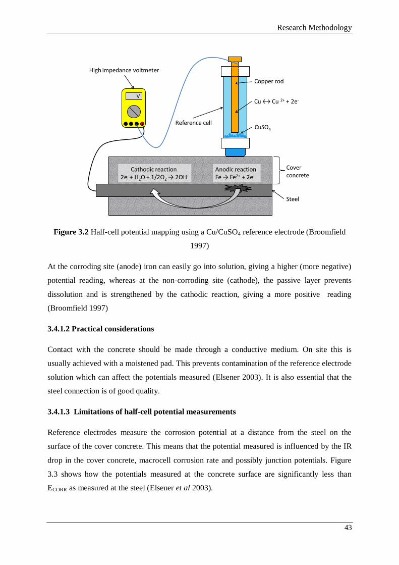
Research Methodology
43
Figure 3.2 Half-cell potential mapping using a Cu/CuSO4 reference electrode (Broomfield
1997)
At the corroding site (anode) iron can easily go into solution, giving a higher (more negative)
potential reading, whereas at the non-corroding site (cathode), the passive layer prevents
dissolution and is strengthened by the cathodic reaction, giving a more positive reading
(Broomfield 1997)
3.4.1.2 Practical considerations
Contact with the concrete should be made through a conductive medium. On site this is
usually achieved with a moistened pad. This prevents contamination of the reference electrode
solution which can affect the potentials measured (Elsener 2003). It is also essential that the
steel connection is of good quality.
3.4.1.3 Limitations of half-cell potential measurements
Reference electrodes measure the corrosion potential at a distance from the steel on the
surface of the cover concrete. This means that the potential measured is influenced by the IR
drop in the cover concrete, macrocell corrosion rate and possibly junction potentials. Figure
3.3 shows how the potentials measured at the concrete surface are significantly less than
ECORR as measured at the steel (Elsener et al 2003).
V
CuSO4
Cu ↔ Cu 2+ + 2e-
Cathodic reaction 2e- + H2O + 1/2O2 → 2OH-
Anodic reaction Fe → Fe2+ + 2e-
Reference cell
Cover concrete
Steel
Copper rod
High impedance voltmeter

Research Methodology
44
Figure 3.3 Schematic view of the electric field and current flow in an active/passive
macrocell on steel in concrete (after Elsener 2001 and Elsener et al 2003)
Steel potentials are influenced by the moisture content of the cover concrete which will alter
its resistance. Wet concrete can over-state the corrosion risk and in saturated concrete the
potentials measured will be very negative due to a lack of oxygen at the cathode. Cracking,
carbonation of the surface and aggregate type can also lead to misleading results. It is also
critical that the reference electrode is frequently calibrated or the reference potential of the
probe itself can change, leading to erroneous readings.
3.4.1.4 Interpretation of potential data
ASTM C876 (2009) divides steel corrosion potentials into three broad categories which relate
measured potentials to the corrosion condition of the steel (see Table 3.1). Although a useful
guide, the factors discussed in Section 3.4.1.3 can influence the data collected, meaning that
caution should be exercised when interpreting the data collected.

Research Methodology
45
Table 3.1 Embedded steel corrosion potential interpretation (ASTM C876 - 09 (2009))
Half-Cell Potential Reading (mV) Corrosion Activity
CSE
SCE
>-200
-200 to -350
<-350
>-125
-125 to -275
<-275
Greater than 90% probability of no corrosion
An increasing probability of corrosion
Greater than 90% probability of corrosion
Half-cell potential measurement techniques are also extensively used to characterise electrode
behaviour during laboratory polarisation experiments and corrosion rate experiments
(Sections 3.4.2, 3.4.3 and Paper 1 (Appendix B)).
3.4.1.5 Summary
The CPM technique was selected primarily due to the versatility of its application to the
characterisation of corrosion processes. Reference electrodes can be used to assess the
condition of embedded steel, as well as the effect of electrochemical treatments and climatic
changes on corrosion processes. Their use is also essential in LPR and potentiodynamic
polarisation experiments. The main reasons for selection are as follows:
o Other than when used as part of a more complex experimental arrangement such as
LPR, the equipment used is portable and can be used in almost any conditions.
o The technique only requires a reference electrode, high input impedance voltmeter and
a tapped and drilled or riveted connection to the steel in order to function.
o Data can be generated instantly and the equipment is simple to maintain and calibrate.
o Although the data generated is qualitative in nature when measuring buried steel, the
CPM technique is extremely useful when used comparatively or to give indicative
measurements.
3.4.2 Potentiodynamic Polarisation
Direct Current Potentiodynamic Polarisation (PP) can be used to elucidate information
regarding the electrochemical processes occurring on an electrode surface at different
electrode potentials. The same basic experimental technique can be used to obtain information

Research Methodology
46
such as the pitting susceptibility and corrosion rate of a metal as well as its cathodic or anodic
behavioural characteristics.
3.4.2.1 Theory and scan features
For an electrochemical process to take place there must be an anode, cathode and both an
ionic and electronic conductive path between the two. In polarisation experiments, the
electronic path is provided by a potentiostat, and the ionic path by the test solution that
separates the working and counter electrodes. The potentiostat provides the ‘driving force’ for
the reactions occurring at the working electrode surface and the magnitude of this driving
force will determine which electrochemical processes occur at the electrodes as well as their
rates.
At the anode, oxidation takes place:
M → Mx+
+ xe-
(3.1)
Where M represents the metal, Mx+
represents the ion of the metal, and xe- represents the
number of electrons transferred in the process. It should be noted that the oxidation of other
metals, not necessarily the one under investigation can also occur (e.g., ferrous (Fe2+
) ions
may be oxidised to ferric (Fe3+
) ions). At sufficiently positive potentials, oxygen production
may also occur:
2OH- → ½O2 + H2O + 2e
- (3.2)
At the cathode, reduction takes place, commonly the reduction of an oxide or hydroxide:
Mx(OH)y + ye- → xM
+ + yOH (3.3)
Or, at sufficiently negative potentials, water reduction may take place in aqueous
environments:
H2O + e- → H + OH
- (3.4)
An anodic polarisation scan of a metal in solution is shown in Figure 3.4. It should be noted
that this is a typical scan illustrating some of the regions present on an anodic polarisation
scan. Depending on the metal and solution under test, some or all of these regions may be
present. The scan starts at (1) and moves in the positive direction until termination at (2).

Research Methodology
47
There are several notable features of the scan denoted by the letters A to F (Enos and
Scribner, 1997):
Position A – The ‘open circuit’ potential, where the sum of the anodic and cathodic reactions
at the working electrode equals zero, i.e., the measured current is zero.
Point B – As the potential increases the reaction rates at the surface increase and we move
into the ‘active’ region where the dominant anodic reaction is metallic dissolution.
Point C – Is known as the passivation potential or critical current, and as the applied potential
increases above this value the current density decreases with increasing potential (Region D),
until a low, passive current density is achieved in Region E.
Point F – At a sufficiently positive potential, the applied current increases rapidly. Depending
on the metal and the solution this can be as a result of several factors including pitting
corrosion, transpassive dissolution or oxygen evolution for metals with a very protective
oxide layer.
The potentiostat measures the amount of current (x axis) which it must apply to achieve the
desired level of polarisation (y axis).
Figure 3.4 Typical anodic Log current/potential scan (Enos and Scribner 1997).

Research Methodology
48
The current represents the rate of the reaction(s) occurring on the working electrode surface
and is usually expressed as Log current density (current/surface area). The reaction rate will
be influenced by temperature, solution chemistry and the condition of the surface being
examined.
3.4.2.2 Typical experimental technique
A typical experimental arrangement for potentiodynamic polarisation can be seen in Figure
3.5. The potentiostat increases the working electrode potential with respect to a reference
electrode by passing current from a counter electrode. The current required to obtain the
desired potential is recorded along with the potential of the working electrode surface. The
rate at which the working electrode potential is altered is commonly termed the ‘scan rate’.
The potential is usually ramped from the corrosion potential, which is the steady state
corrosion potential of the metal in the experimental solution.
Figure 3.5 A typical test arrangement for a potentiodynamic polarisation experiment.
3.4.2.3 Experimental considerations
The scan rate for the experiment must be chosen carefully as an incorrect rate can lead to
misinterpretation of the polarisation curve features. If the rate is too rapid, the system does not
have the chance to stabilise and some of the measured current represents charging of the
VA
Salt bridge
Working electrodeCounter electrode Reference electrode
Potentiostat

Research Methodology
49
surface capacitance (Zhang et al 2009). The result is that features of the scan, such as pitting
potential or passivation potential are moved to more positive values. Sazou et al (2012) found
that the scan rate affected the breakdown potential of titanium in 0.7M KBr significantly, with
2.3V being reported at 10 mV/s and 10.4V at 200 mV/s. The ASTM scan rate is 0.1667 mV/s
(ASTM G59 – 97(2009)), although it is common for the most suitable scan rate for a given
system to be determined experimentally.
It should be noted that the current measured during these experiments is the total current,
which may represent current resulting from other reactions on the electrode surface and not
just the reaction of interest to the investigation (Enos and Scribner 1997, Silverman 1998).
This means that a significant and changing proportion of the measured current may be
accounted for by secondary reactions.
3.4.2.4 Summary
The PP technique was selected as it can be used to characterise the corrosion processes
occurring on the surface of any metallic electrode in both liquid and concrete electrolytes.
Relevant to the current work, it allows the investigator to assess the effectiveness of a coating
in protecting against corrosion, the effectiveness of an anode material in passing current and
the corrosion events activated by increasing potentials.
The main reasons for selection are:
o The experimental set-up is simple, rapid and repeatable and the equipment is readily
available
o The flexibility afforded by the same basic technique (scan rate, range of potentials,
materials)
3.4.3 Linear polarisation resistance techniques
Linear polarisation resistance measurement (LPR) techniques use steel polarisation and
applied current density measurements to determine Rp (the polarisation resistance) and
calculate the instantaneous steel corrosion rate. Depending on the potential shift affected by
the technique, one of two basic calculations is used.
Small potential perturbations can be applied to large reinforced structures in order to calculate
the steel corrosion rate (Sul et al 2001). The technique can be performed potentiostatically by

Research Methodology
50
perturbing the steel potential ΔE by a fixed amount and monitoring the current decay Δi over
a fixed time or galvanostatically by applying a small fixed current to the reinforcing steel and
monitoring the potential change, again, after a fixed time period. If ΔE remains between 10-
30 mV the polarisation resistance of the steel, Rp, can be calculated from Equation 3.5.
Rp = ΔE/Δi (3.5)
From this, the corrosion rate can be calculated:
icorr = B/Rp (3.6)
Where B is the Stern-Geary constant which can be derived empirically from weight loss
measurements or calculated from βa and βc, the anodic and cathodic Tafel slopes (the linear
regions of the polarisation curve for the anodic and cathodic reactions) (Eqn. 3.7)
B = βaβc/2.303(βa+βc) (3.7)
B is taken to be ~26 mV for corroding steel and ~50 mV for passive steel. In order to attain an
accurate value for iCORR, the surface area of the polarised steel (A) must be known:
icorr = icorr/A (3.8)
This method and its derivatives have been used extensively on large reinforced structures
(Andrade and Alonso 1996 and Andrade et al 2004)
The experimental method usually involves using a small counter electrode on the surface of
the cover concrete to shift the steel potential. If the depolarisation during testing is >30 mV
then Equation 3.9 can be used to more accurately calculate the instantaneous corrosion rate:
(3.9)
where iappl is the applied current density, icorr is the corrosion rate, ΔE is the steel potential
shift (corrected for IR drop) and βa and βc are the anodic and cathodic Tafel slopes
respectively (Glass et al 2008). This technique was used to determine corrosion rates in Paper
1 (Appendix B) by disconnecting the steel from the anode and recording the depolarised
potential after a fixed time.
ac
appl
corr
EE
ii
3.2exp
3.2exp

Research Methodology
51
3.4.4 Impedance analysis
Impedance analysis involves changing experimentally acquired time-domain coulostatic
transients into the frequency domain. Practically, this is achieved by recording the effect of a
measured, short current pulse on the steel corrosion potential.
3.4.4.1 Impedance theory
According to Ohm’s law for direct current (DC):
R = ΔE/Δi (3.10)
Where R is resistance, ΔE is voltage and Δi is current. However for alternating (AC) current,
the resistance is frequency dependent, having both a magnitude and phase angle and is
referred to as impedance. Impedance (Z) is often represented as frequency dependent x and y
components or real (Re) and imaginary (Im) in a complex number form. This is represented
graphically in Figures 3.6 and 3.7.
Figure 3.6 Impedance represented as a magnitude (Δi and ΔE) and phase angle (θ)
Figure 3.7 Mathematical representation of impedance

Research Methodology
52
Using the Laplace transform it is possible to obtain frequency data at any given frequency
();
At , ΔE = c + jd (3.11)
and
At , Δi = e + jf (3.12)
Therefore:
Z = (c + jd)/(e + jf) (3.13)
If the current pulse period is smaller than the period of cycle (reciprocal of frequency) then
the Laplace transform of the current pulse is its charge. Therefore, the impedance is the
Laplace transform of the potential transient (ΔE(t)), divided by the charge passed during the
current pulse (q), or:
(3.14)
For a particular frequency, the area under the transient curve is calculated and divided by the
charge passed during the current pulse to provide the Real (cos) and Imaginary (sin)
components which can then be plotted for different frequencies on an impedance (Nyquist)
chart (Figure 3.8).
The polarisation resistance is determined from where the impedance plot meets the low
frequency intercept on the real (Re) axis. Eqn. 3.6 can then be used to determine the corrosion
rate. A ‘fuller’, semi-circular plot is indicative of passive steel (Figure 3.8. (a)) whereas a
more ‘flattened’ plot indicates corroding steel (Figure 3.8. (b)) (Glass et al 1998)
dttsintE1
dttcostE1
dc Z00
q
jq
j

Research Methodology
53
Figure 3.8 Impedance plots for (a); passive steel and (b); actively corroding steel (Glass et al
1998)
The impedance analysis technique was used to calculate instantaneous corrosion rates in the
work described in Section 4.2.2 and in Paper 1 (Appendix A).
3.4.4.2 Practical considerations
A pulse of DC current is applied to the steel for ~1 second and the effect on the steel potential
is measured by a surface-mounted reference electrode. A data logger measuring several times
per second is typically used to collect both sets of data. The total charge passed during the
pulse and the resulting potential transient are used to work out the impedance at different
frequencies.
3.4.4.3 iCORR measurement accuracy using polarisation resistance methods
To obtain an accurate iCORR using the LPR method it is important to know an accurate surface
area of the steel that is polarised by the counter electrode. The area polarised has, in the past
been assumed to be that directly under the counter electrode, although recent work has proved
that current flowing from the counter electrode can affect a much wider area, thus adding
considerable inaccuracy into the value of the corrosion current density (Andrade et al 2004).
Systems that incorporate a second ‘guard ring’ counter electrode, to provide a ‘confinement’
current which attempts to limit the surface area polarised (and thus more accurately estimate
the polarised surface area) have been developed with the intention of reducing this inaccuracy
(Wojtas 2004, Law et al 2000), but it remains a considerable variable during these

Research Methodology
54
measurements as steel arrangement and geometry vary widely and will have an influence. In
addition, the method assumes that the cathodic Tafel slope remains constant during
depolarisation; with large de-polarisations, this is questionable.
As no current flows during the recording of the transient, the results are not affected by mass-
transfer caused by the perturbation. The impedance calculation may over-estimate the
corrosion rate as the potential transient is only measured for several minutes following the
pulse whereas its effect may last much longer (Glass et al 1998)
3.4.4.4 Summary
The impedance and LPR methods have been selected as experimental methods as Rp values,
experimentally determined, can be used to calculate the instantaneous corrosion rate of steel
in concrete.
The application of these techniques allows the assessment of the effectiveness of cathodic
protection systems in halting corrosion and the effect of treatment parameters.
The main reasons for selection over other methods are:
o The simplicity of test equipment and the test methods themselves
o The LPR technique would only be used on laboratory samples, therefore the
limitations of known polarised surface area associated with LPR techniques used on
structures were not applicable, meaning greater accuracy
o The impedance analysis technique, although not widely used, has been shown to give
similar iCORR values to LPR techniques when applied on the same samples (Glass et al
1998 and Glass 1995)
3.5 EXPERIMENTAL DESIGN CONSIDERATIONS
Aims 1 and 2 demanded the characterisation of the corrosion activity affecting steel/anodes
embedded in concrete and this, in turn, demanded the production of concrete samples in
which to contain the steel and anode(s). These samples had to simulate a variety of conditions
and allow measurement of a variety of experimental parameters. In this section the
requirements for concrete sample design and production will be discussed as well as the use
of common data acquisition methods.

Research Methodology
55
3.5.1 Concrete sample design
Figure 3.9 shows the key factors to consider when designing and manufacturing concrete
samples for experimental studies. Each factor is then discussed, with examples, below.
Considerations that were specific to individual experiments are not discussed here, but can
instead be found in Chapter 4.
Figure 3.9 Concrete sample design considerations
Mix design fit for purpose – For example, if the steel inside the sample is required to corrode
prior testing, a weak and porous mix with mixed in chloride is well suited. If a sample is
required to represent bridge conditions then this would be completely unsuitable.
Monitoring requirements considered – Steel and anode cabling may need to be accessible for
measurement/monitoring. The positioning of reference electrodes close to the element of
interest is extremely important.
Representative of relevant conditions – For example the chloride content of the concrete,
exposure to specific climatic conditions (for example temperature and relative humidity) the
anode to steel ratio being representative of site, the correct concrete mix design (see above).
Concrete test
sample
Mix design fit for purpose
Monitoring requirements
considered
Representative of relevant conditions
Consistent & repeatable
manufacture
Geometrically suitable

Research Methodology
56
Consistent and repeatable manufacture – Concrete by its nature is inhomogeneous and even
samples made with the same mix design in different batches can lead to a large variety in
measured potentials and corrosion rates due to differences in compaction and aggregate
positioning. It is important then, that consideration be given to the mix components, moulds
and schedule for manufacture including the curing regime.
Geometrically suitable – The sample must be able to accommodate the required amount of
steel to achieve the correct anode to steel ratios. If measurement of the anode influence is
required then the steel should be arranged and cover concrete designed to facilitate this.
3.5.2 Data collection
The aims and objectives frequently demanded that sample data be collected at regular
intervals from experimental arrangements located at manned and un-manned sites. Depending
on the measurement requirements, complexity and convenience either manual or automated
readings were taken with either a digital multimeter or automated data-logger arrangement.
These two methods are discussed below in terms of their practical application, benefits and
limitations.
3.5.2.1 Digital multimeters
Multimeters can be used to accurately measure a wide range of electrical phenomena
including current, voltage, resistance and steel reference potentials. Depending on the make
and model, different equipment resolutions and accuracies are available. A mid-range
handheld multimeter will generally have an accuracy of 0.5% (Fluke Corporation 2012).
During operation it is critical that the input impedance of the circuit is greater than the circuit
of interest (voltage) and lower than the circuit of interest when measuring current.
Human errors such as poor physical connections and the use of incorrect settings and
terminals can lead to incorrect/inaccurate measurements being taken. Maintenance and
calibration of meters is important to attain accurate and consistent results.
3.5.2.2 Data logging equipment
Data loggers use electronic means to periodically record environmental/equipment output data
using a variety of different sensors. Following a collection period, data can be downloaded via
a physical connection or remotely using a built-in modem. Data loggers allow measurements
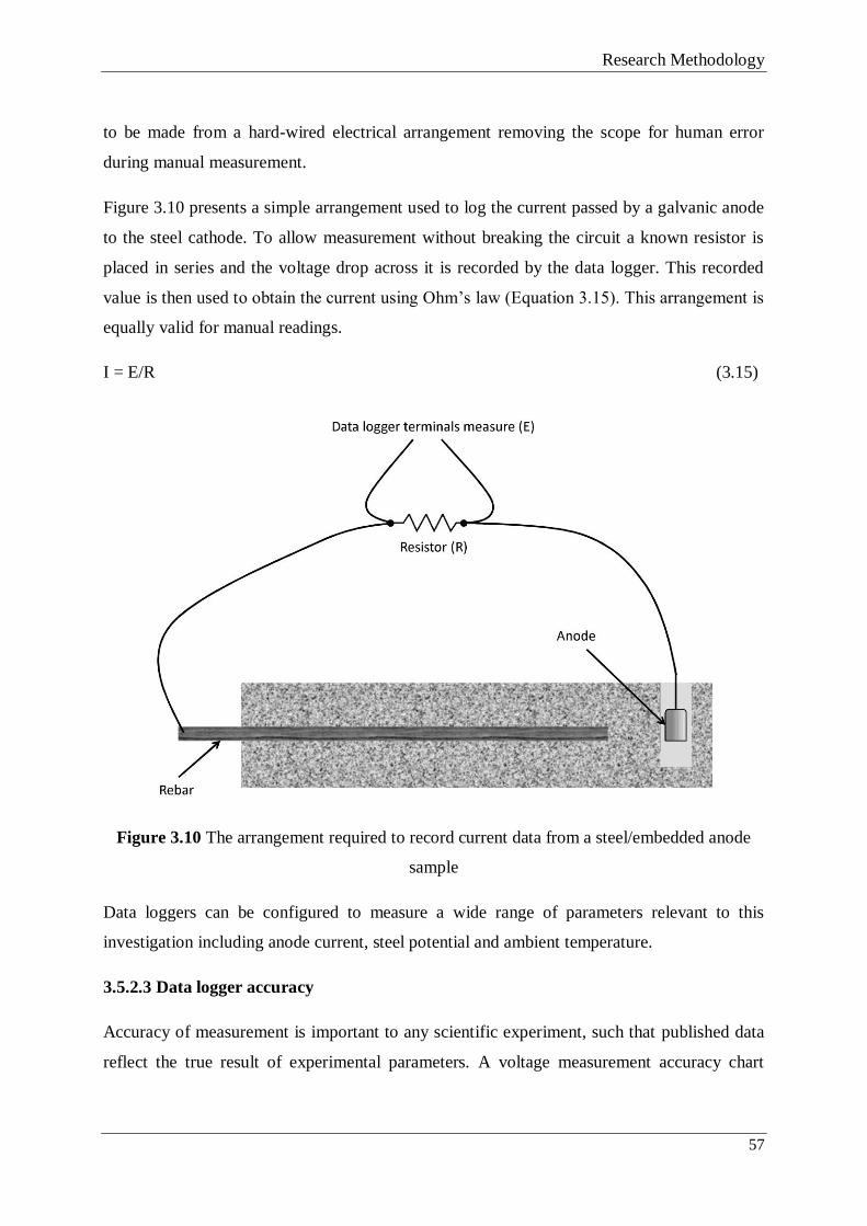
Research Methodology
57
to be made from a hard-wired electrical arrangement removing the scope for human error
during manual measurement.
Figure 3.10 presents a simple arrangement used to log the current passed by a galvanic anode
to the steel cathode. To allow measurement without breaking the circuit a known resistor is
placed in series and the voltage drop across it is recorded by the data logger. This recorded
value is then used to obtain the current using Ohm’s law (Equation 3.15). This arrangement is
equally valid for manual readings.
I = E/R (3.15)
Figure 3.10 The arrangement required to record current data from a steel/embedded anode
sample
Data loggers can be configured to measure a wide range of parameters relevant to this
investigation including anode current, steel potential and ambient temperature.
3.5.2.3 Data logger accuracy
Accuracy of measurement is important to any scientific experiment, such that published data
reflect the true result of experimental parameters. A voltage measurement accuracy chart

Research Methodology
58
produced by the manufacturer of equipment used for the majority of the work is shown in
Figure 3.11.
Logged data was only ever used in a comparative way (to compare current passing in blocks
with different chloride levels exposed to the same environment for example) and to identify
trends, never to record standalone data. Figure 3.11 shows that the percentage error is
lower in measurements of higher potential. Attempts were made wherever practical to keep
the range of measured potentials above 20 mV (and therefore a 5% error) by using suitable
resistors (Figure 3.10).
Figure 3.11 CR1000 data logger voltage measurement accuracy (0º to 40ºC) (Campbell
Scientific Inc. 2011)
Although accurate and versatile, data loggers can be limited by their battery life (when a
permanent power source cannot be provided), voltage measurement range and software
issues; however the main source of poor data is generally the inexperience of the operator.
3.6 SUMMARY
This section introduced the research methodology that has been adopted during the
investigations and discussed the requirements of the applied research techniques before
briefly introducing potential techniques. The chosen research techniques were then discussed

Research Methodology
59
in more detail and their use justified in the context of the research. Finally the experimental
design considerations were discussed.

Research Undertaken & Findings
60

Research Undertaken & Findings
61
CHAPTER 4 - RESEARCH UNDERTAKEN AND FINDINGS
This section of the thesis details the tasks carried out to achieve the aims and objectives
discussed in Chapter 1 and the findings of these investigations. The Chapter is split into three
parts to reflect the three aims presented in Table 1.1 and should be read alongside the
appended Papers 1 to 4 (Appendices B-E).
4.1 CHARACTERISATION OF THE HYBRID ANODE SYSTEM – PART 1
This section will detail the work completed to achieve Aim 1 – “Characterise the
electrochemical processes occurring in hybrid anode laboratory samples using common
industry techniques” through Objectives 1 and 2 detailed in Sections 1.4.1 and 1.5. One half
of this work is substantially presented in the published appended Paper 1 (Appendix B) and as
a result, this section will refer to this document whilst adding a narrative to explain the
thought process behind the project and details regarding the methods used in the analysis. The
second half of this work has not been published elsewhere and will be examined in more
detail.
4.1.1 Preliminary studies
Prior to the commencement of experimental work, a literature review was undertaken which
focused on concrete and the corrosion of steel in concrete. This led to greater understanding
of:
1. Concrete chemistry and composition and its influence on steel passivity.
2. Concrete mix design and corrosion acceleration techniques.
3. The situations and chemistry involved in steel de-passivation and corrosion (Section
2.3.1).
4. The nature of the corrosion occurring on the steel surface and the factors influencing
its progress and spread (Section 2.3)
5. The theory behind and practical aspects of the experimental techniques used to
characterise and quantify steel corrosion (Sections3.3 and 3.4)
Following the literature review, consideration was given to the training that would be most
beneficial to both the RE and sponsor company. The array shown in Figure 4.1 gives the four

Research Undertaken & Findings
62
learning outcomes that were deemed the most important and how these informed the
experiments undertaken and the samples selected/made.
Figure 4.1 Learning outcome requirements and the resultant experimental techniques
required of the hybrid anode samples used for the study
4.1.2 Experimental considerations
It was clear from the outset that the requirements of the experimental techniques were
different and distinct. In order to cover each of the learning outcomes shown in Figure 4.1 in a
timely fashion and in some detail it was deemed necessary to cast some new concrete samples
and to acquire existing samples for testing. Sample set 1 was a single sample and is described
in Appendix B. Mix details can be found on page 152. Sample set 2 was a collection of
samples containing a variety of chloride contents described in Appendices C and D. The
samples were produced according to the requirements discussed in Section 3.5 and tailored to
achieve the desired objectives.
Measurement of corrosion protection• Corrosion rate measurement
• De-polarisation technique• Impedance analysis
technique
Steel/anode potential measurement Practical & effective use of reference electrodes Relationship between anode and steel potential. Steel potential response to anode system
Data logging equipment configuration Learn how to physically wire the data-logger to obtain current and potential data Programme and operate the attendant software
Anode current measurement• Choice of resistors• Wiring into the circuit• Calculating current density & charge passed
Anode influence on steel potential• Magnitude and extent of steel polarisation • Characterisation of polarisation changes during the two phase treatment
Sample set 2
Concrete/steel sample preparation Water to cement ratio Chloride addition Embedding the steel Effect of concrete composition and chloride content on anode system and steel
Sample set 1
Experimental techniques
Learning outcomes
Sample

Research Undertaken & Findings
63
4.2 TASK 1 – MEASUREMENT OF CORROSION PROTECTION – SAMPLE
SET 1
4.2.1 Linear polarisation resistance
Linear polarisation resistance and impedance analysis techniques were used to characterise
the corrosion condition of the steel (Aim 1).
4.2.1.1 Research Method
Linear polarisation resistance (LPR) measurement techniques use steel polarisation and
applied current density measurements to determine Rp and calculate the instantaneous steel
corrosion rate. These techniques are discussed in Sections 3.4.3 and have been applied in the
study described in Paper 1 (Appendix B), where a detailed description of the method can be
found.
A technique widely applied when assessing the protection offered by cathodic protection
systems involves the measurement of the steel potential when the protection current is
removed. Embedded reference electrodes are generally installed for this purpose and the
current European Standard states a range of de-polarisation criteria which signify passive
corrosion rates (BS EN 12696, 2012).
The process, whether it is applied on site or in the laboratory follows the same basic steps:
1. Following interruptions during experimental set-up, make sure a stable current reading
is obtained.
2. Measure the steel potential using a fixed reference electrode.
3. Disconnect the anode from the steel, measuring the instant off potential (within the
first 0.5 seconds).
4. Allow the potential to decay for up to 24 hours.
5. With accurate knowledge of the steel surface area, current density and potential decay
(minus IR drop), use Equation 3.9 to calculate the corrosion rate.
In the current work, a data logger was used to measure both the anode and steel potentials.
The same data logger was also used to activate a reed switch which triggered a high rate
logging multimeter, enabling an ‘off’ potential measurement between 0.02 and 0.07 s after

Research Undertaken & Findings
64
interrupting the galvanic current. The steel was then left to de-polarise for approximately 10
hours; a section of the resulting depolarisation can be seen in Figure 4.2.
4.2.1.2 Research Findings
Figure 4.3 shows an example of the theoretical corrosion rate as a function of the potential
shift induced by an applied current density of 4.1 mA/m2
that was calculated for the present
sample (Paper 1). Corrosion is deemed negligible when a corrosion rate of less than 2 mA/m2
is measured (BS EN 12696, 2012). From Figure 4.3, it can be seen that a depolarisation of
greater than 40 mV would signify passive steel. IR-drop corrected steel de-polarisations of
346 and 265 mV were recorded when the experiment was carried out at 2 and 4.5 years,
signifying corrosion rates of 0.0054 and 0.0024 mA/m2 respectively (Figure 4.3).
Figure 4.2 Anode and steel depolarisation following disconnection (carried out after 2 years)
After 4.5 years, the ability of the anode to polarise the rear of the steel plates was assessed
(Figure 9, Paper 1 (Appendix B)). The exercise showed that the anode was adequately
throwing current to and protecting the steel, in spite of the challenging geometry that it
presented.
-1000
-900
-800
-700
-600
-500
-400
-300
-200
0 10 20 30 40 50 60
Po
ten
tia
l (m
V)
vs. S
CE
Time (Minutes)
Steel
Anode
IR Drop = 62 mV

Research Undertaken & Findings
65
Figure 4.3 Theoretical corrosion rate calculated as a function of potential at an applied
current density of 4.1 mA/m2, (Holmes et al 2011)
The de-polarisation measured will depend heavily on the distance of the anode from the
reference electrode with increasing de-polarisations being expected the closer to the anode
due to the increasing influence it has on the steel. The steel potential was therefore measured
at a location half-way in between the steel and the anode to ensure a fair representation of the
corrosion conditions, a standard practice on site installations.
4.2.2 Impedance analysis
The theory pertaining to the impedance analysis technique was discussed in Section 3.4.4.1
and was informed by the experiments of Glass et al (1998). It has since been used by
Christodoulou et al (2010 and 2012) in both laboratory and site conditions to measure the
corrosion condition of embedded steel.
4.2.2.1 Research Method
The technique involved the application of a pulse of direct current to the steel for ~1 second
using the embedded anode, and logging the effect on the steel’s potential using a surface-
0.001
0.01
0.1
1
10
0 50 100 150 200 250 300 350 400
Co
rro
sio
n R
ate
(m
A/m
2)
Potential Shift (mV)
Passive Corrosion Rates
Active Corrosion Rates
2 years
4.5
years

Research Undertaken & Findings
66
mounted reference electrode. A data logger measuring several times per second was used to
collect the current pulse data. The total charge passed during the pulse and the resulting
potential transient (Figure 4.4) were then used to calculate the impedance at different
frequencies.
Figure 4.4 Potential/time transient following the 1 second current pulse
The test required that the steel be at its de-polarised, natural corrosion potential, so the
experiment was undertaken following the de-polarisation work discussed in Section 4.2.1.2.
The impedance plot obtained from the sample had a ‘full’ shape (Figure 4.5) which suggested,
along with the calculated corrosion rates from the experiment and depolarisation work, that
the steel in the sample was not corroding (Glass et al 1998, Christodoulou et al 2010).

Research Undertaken & Findings
67
Figure 4.5 Impedance spectrum obtained from the experimental sample
4.2.2.2 Research Findings
The steel response to the current pulse of 0.887 mA.s during the impedance experiment
resulted in a Rp of 1008.72 Ohm.m2 and a corrosion rate of 0.025 mA/m² after 2.5 years using
Equation 3.6.
The difference in the calculated corrosion rates obtained from the two different techniques
could be due to two main reasons; firstly, the impedance calculation may over-estimate the
corrosion rate as the measured potential transient was only 500 seconds long, and secondly, it
is assumed that the cathodic Tafel slope remains constant at 120 mV during depolarisation.
With such a large de-polarisation this is questionable.
4.3 TASK 2 – ANODE INFLUENCE ON STEEL POTENTIAL – SAMPLE SET 2
The installed anode influence can be measured using half-cell potential mapping of the steel
that it protects. The potential values recorded effectively measure the degree to which the
steel is being polarised by the anode and are used in the European Standard BS EN 12696
(2012) to establish the protection that installed cathodic protection systems provide. This
section of work has not been published elsewhere, and so will be discussed in some detail.
4.3.1 Research Method
The samples (containing either 0, 1, 2.5 or 5% chloride by weight of cement) used in the
study are described in Papers 2 and 3 (Appendices C and D), as they were later used for the
work detailed in Section 4.7. Markings were made along the centre of the sample at 50 mm
0
100
200
300
400
0 200 400 600 800 1000 1200
Im [Z
] (O
hm
s.m
2)
Re [Z] (Ohms.m2)
0.0005 Hz
0.05 Hz
0.02 Hz

Research Undertaken & Findings
68
intervals moving away from the anode to allow consistent measurement of the steel potential
using a high impedance voltmeter and portable reference electrode (Figure 4.6). A steel
connection was made using a crocodile clip onto sheathed copper wire which had been riveted
to the rebar. Table 4.1 explains the sample notations used.
Table 4.1 Sample name and mixed-in chloride content (‘wt%’ = percentage by weight of
cement)
Sample name 0wt%A 0wt%B 1wt%A 1wt%B 2.5wt%A 2.5wt%B 5wt%A 5wt%B
Chloride
content (wt%) 0 0 1 1 2.5 2.5 5 5
Figure 4.6 Concrete block with varied chloride contents (all measurements in mm)
Figure 4.7 illustrates the steel potential measured on the first day of the 12V driven impressed
current phase of the hybrid treatment. The same exercise was repeated on days 3 and 7 during
the impressed current phase and for several days following the switch into the galvanic mode
of operation.
4.3.2 Research Findings
This section presents the findings of Task 2, for ease of interpretation it is split into two
sections; the impressed current and galvanic phases of the treatment.
120
120
120
600
AnodeMortar
Rebar
30
Chloride contaminated concrete

Research Undertaken & Findings
69
4.3.2.1 Impressed current phase
Measuring the polarisation gives an indicative measure of the influence of the installed anode
on the steel corrosion reaction (see Section 3.4.1). As can be seen from Figure 4.7 the chloride
level in the blocks had an effect on the degree of polarisation seen, with the degree of
negative shift generally correlating with the amount of chloride in the concrete, especially
close to the anode. The potential decay as the reference electrode was moved away from the
anode was similar for all of the blocks, rising quite rapidly before reaching a steady state
between 250 and 350 mm from the anode. This indicates that the chloride content of the
blocks has limited effect on the distance the anode can throw the bulk of its current during the
impressed current phase of the treatment.
Figure 4.7 Steel potential measurements moving down the block from the anode (0 mm) after
30 minutes on the first day of the impressed current phase
Figure 4.8 shows the impressed current phase of the sample containing 1 wt% chloride. It can
be seen that the closer that the end of the treatment becomes the more positive the potential of
the anode. Samples containing all four chloride levels displayed the same behaviour. This is
-10
-8
-6
-4
-2
0
0 100 200 300 400 500 600
Stee
l po
ten
tial
(V
) vs.
SC
E
Distance from installed anode (mm)
0 wt% A
0 wt% B
1 wt% A
1 wt% B
2.5 wt% A
2.5 wt% B
5 wt% A
5 wt% B

Research Undertaken & Findings
70
likely to have been caused by anode polarisation and the build-up of corrosion products at the
anode surface resulting in an increase in resistance to current flow.
Figure 4.8 Steel potential changes over the course of the 7 day DC impressed current
treatment (1 wt% A)
4.3.2.2 Galvanic phase
After 7 days in impressed current mode, the DC power supply was removed and the anode
connected directly to the steel to pass current galvanically. As with the impressed current
phase, the influence of the anode decays rapidly before reaching a steady state between 150
and 250 mm from the anode (Figure 4.9).
Following the removal of the 12V DC current the magnitude of the polarisation effect on the
steel was reduced dramatically (from ~6.5 V 50 mm from the anode to -1 V). Figures 4.9 to
4.12 show the change to the mixed potentials of the various samples at 1, 3, 8, 10 and 17 days
following the switch to galvanic mode as well as 1 and 28 days before the impressed current
phase. In all cases over the period measured there was a positive potential shift associated
with the continuing de-polarisation of the steel towards a stable galvanic potential.
-7
-6
-5
-4
-3
-2
-1
0
0 100 200 300 400 500 600
Ste
el p
ote
ntia
l (V
) v
s. S
CE
Distance from anode (mm)
Day 1
Day 3
Day 7

Research Undertaken & Findings
71
Figure 4.9 Galvanic steel polarisation changes over a 17 day period in the 0 wt%A chloride
sample
Figure 4.10 Galvanic steel polarisation changes over a 17 day period in the 1 wt%A chloride
sample
-400
-300
-200
-100
0
100
200
0 100 200 300 400 500 600
Stee
l po
ten
tial
(m
V) v
s. S
CE
Distance from installed anode (mm)
Day 17
Day 10
Day 8
Day 3
Day 1
Day -1
Day -28
-800
-700
-600
-500
-400
-300
-200
-100
0 100 200 300 400 500 600
Stee
l po
ten
tial
(m
V) v
s. S
CE
Distance from installed anode (mm)
Day 17
Day 10
Day 8
Day 3
Day 1
Day -1
Day -28

Research Undertaken & Findings
72
Figure 4.11 Galvanic steel polarisation changes over a 17 day period in the 2.5 wt%A
chloride sample
Figure 4.12 Galvanic steel polarisation changes over a 17 day period in the 5 wt%A chloride
sample
-1100
-1000
-900
-800
-700
-600
-500
-400
-300
0 100 200 300 400 500 600
Stee
l po
ten
tial
(m
V) v
s. S
CE
Distance from installed anode (mm)
Day 17
Day 10
Day 8
Day 3
Day 1
Day -1
Day -28
-900
-800
-700
-600
-500
-400
0 100 200 300 400 500 600
Stee
l po
ten
tial
(m
V) v
s. S
CE
Distance from installed anode (mm)
Day 17
Day 10
Day 8
Day 3
Day 1
Day -1
Day -28

Research Undertaken & Findings
73
The data represented by Day -1 and Day -28 in Figures 4.9 to 4.12 is taken from potential
maps performed 1 and 28 days before the start of the impressed current phase of the
treatment. The mapping was completed before the anode had been installed and used the same
reference electrode that was used for all subsequent potential measurements.
As expected, the greater positive shift occurred closest to the anode with it’s effect
diminishing as the far end of the sample was approached. The average potential shift at 500
mm from the anode was 67 mV between days 1 and 8 and 54 mV between days 8 and 17,
compared with 327 and 66 mV recorded 50 mm from the anode.
The degree of polarisation effected by the anode was dependent on the chloride content of the
concrete, with both the 2.5 and 5 wt% sharing similar levels of polarisation. Increasing the
amount of chloride appears to have a diminishing effect on the amount of polarisation
achieved during the galvanic phase. This effect was less pronounced in the impressed current
phase of the treatment.
4.3.3 Discussion
The potentials presented from the galvanic phase were technically “mixed steel potentials” as
the steel and anode are connected together and both influence the recorded potential. For a
true assessment of the steel condition, the sample would have to be fully de-polarised (anode
disconnected from the steel) before the readings were taken. The mixed potential close to the
anode is dominated by the anode pulling the steel to more negative potentials, however,
moving away from the anode its influence is continually reduced and the potential gets closer
to a ‘true’ steel potential.
Figures 4.9 to 4.12 show that the positive shift in potential following the removal of the
impressed current is generally far greater between 1 and 3 days. This can be attributed to the
reaction kinetics at both the zinc and steel surface. Following the removal of such a large
negative polarisation, the reaction rates at both electrodes attempt to return to a stable
potential based on the surrounding concrete conditions. This shift is heavily influenced by the
moisture content of the concrete, but in atmospherically exposed conditions, this will occur
rapidly once the current is removed before slowing down as the stable potential is
approached.

Research Undertaken & Findings
74
The disparity in the potentials on days -1 and -28 can be put down to changes in temperature
and moisture as the blocks had been moved indoors 18 hours before the day -28 readings, but
had been indoors for 17 days before the day -1 readings. The disparity appears to be reduced
with increasing chloride content (which may help retain moisture and therefore a steady state)
and more negative potentials, which indicate established corrosion (ASTM C876 – 09 (2009).
It is clear that in the samples containing chloride, the mixed potential following the impressed
current is significantly more positive than the steel potential prior to the treatment, even with
the influence of the anode which has the effect of depressing the mixed potential. This effect
was seen in the work completed for Paper 1 (Appendix B), and had previously been noted by
Glass et al (2008), Christodoulou et al (2010), and is discussed in Paper 4 (Appendix E). It is
proposed by Glass et al (2001) that this is a result of modification of the steel surface during
the impressed current phase brought about by re-alkalisation and the reduction of chloride ion
concentration which leads to steel passivity. The theory behind this effect is discussed in
Section 2.3.
Table 4.2 suggests that negative polarisation greater than ~300 mV during the impressed
current phase was sufficient to cause a significant positive shift in the mixed galvanic
potential 500 mm from the anode in the galvanic phase. It would be expected that the true
steel potentials would be even more positive following disconnection from the anode.
If the steel potential becomes more positive as a result of the impressed current, then the
model proposed in BS EN 12696 (2012) (Figure 2.3) suggests that more current should be
applied to achieve adequate polarisation. However, if this behaviour is examined from the
viewpoint of the pit re-alkalisation/pH maintenance hypothesis, the positive potential shift
would suggest a reduced corrosion risk and therefore a reduction in the need for steel
polarisation.
Table 4.2 The difference between the steel potentials measured on day -1 and day 1 of the
impressed current phase, 500 mm from the anode
Sample
name 0 wt% A 0 wt% B 1 wt% A 1 wt% B 2.5 wt% A 2.5 wt% B 5 wt% A 5 wt% B
Polarisation
(mV) 931 958 441 622 327 450 577 860

Research Undertaken & Findings
75
4.4 SUMMARY
This section presented the details of the tasks undertaken to meet Objectives 1 and2. The
conclusions drawn from this work is discussed in Chapter 5.
4.5 THE RESPONSIVE BEHAVIOUR OF HYBRID/GALVANIC ANODES –
PART 2
This section of the thesis will detail the work completed to achieve Aim 2 – “Investigate the
benefits of the responsive current behaviour of cathodic protection systems and discuss with
regards to existing steel protection hypotheses and criteria”. This work is substantially
reported in the appended Papers 2, 3 and 4 (Appendices C – E) as a result, this section will
refer heavily to these documents whilst adding a narrative to explain the thought process
behind the project and methods used.
This section presents experiments carried out to achieve the objectives set out in Sections 1.5
This broadly involved the investigation of responsive behaviour phenomena from a variety of
concrete samples and site installations and a review of the literature surrounding concrete
protection criteria (Section 2.2.1).
4.5.1 Preliminary studies
Prior to the commencement of experimental work, a literature review was undertaken which
focused on the environmental factors affecting the corrosion of steel in concrete and the in-
depth theories which inform and under-pin the protection criteria applied to steel in concrete.
This led to greater understanding of:
1. The key variables leading to the responsive behaviour of galvanic/hybrid anodes in
concrete.
2. The factors affecting sacrificial anode system lifetime prediction.
3. The application of protection criteria and the standards governing them (Section
2.2.1).
4.5.2 Experimental considerations
In order to achieve the objectives shown in Table 1.1, careful consideration was demanded of
the experimental design and sample preparation. It was clear from the outset that the
requirements of the work required multiple samples of different design. Three sample sets

Research Undertaken & Findings
76
were used during this part of the EngD research and the design and manufacture of each was
influenced by each of the factors presented in Section 3.5;
SAMPLE SET 3 – Two anode zones consisting of 25 anodes each, installed on a pier of the
Whiteadder road bridge, Northumberland. The effect of temperature and moisture on
protective current was investigated.
SAMPLE SET 4 – Nine concrete slab samples containing 0, 1, 2.5 or 5% mixed in chloride
by weight of cement. These samples investigated the effect of concrete chloride content,
temperature and moisture on protective current (Papers 2 and 3, Appendices C and D).
SAMPLE SET 5 – A single sample comprising of steel and zinc anodes connected to an
embedded steel bar in such a way that they passed a galvanic current to the bar. This sample
investigated the effect of temperature and moisture on the protective current passed by both
anodes (Paper 4, Appendix E).
Consideration was given to the idea of allocating each environmental factor an individual sub-
section, where its influence on current output could be discussed, however each data set
investigated the interaction of at least 2 of the 3 factors. It was felt that this would lead to
unnecessary overlapping of discussion and repetition. As a result the section is written
chronologically, with the discourse and investigation summaries providing an insight into
chosen research path.
Aim 2 was realised by the recording of current data from Sample Set 3, 4 and 5 as detailed in
Papers 2, 3 and 4 (Appendices C – E) respectively.
4.6 TASK 3 – SITE DATA COLLECTION – SAMPLE SET 3
This piece of work aimed to record galvanic current responsive behaviour data from a
cathodic protection system installed on a physical structure and relate this data to the specific
environmental conditions experienced by it. A secondary aim was to use the collected data
and knowledge of the installation to estimate the anode system lifetime.
4.6.1 Research method
Data logging equipment (Campbell Scientific CR1000) was used to record the surface
temperature and galvanic current passed by two zones of anodes installed on a bridge over the
river Whiteadder in Northumbria, UK. The bridge is located some 4 miles from the North

Research Undertaken & Findings
77
Sea. This data was then analysed with regard to daily and seasonal temperature fluctuations
and also the influence of the river below the bridge. The current output from two anode zones
containing 25 anodes (Figure 4.13) was recorded over a 773 day period from late March
2007.
Figure 4.13 Plan of the west-facing pier section housing the upper (red) and lower (blue)
anode zones
Independent monitoring of the two anode zones allowed the influence of the river on the
galvanic current to be assessed as well as changes due to daily and seasonal temperature
fluctuations. No concrete chloride content information was available for the structure and so
this factor was not discussed, however it is likely that the lower bridge section had a higher
chloride content than the upper section due to its proximity to the estuarine waters (Figure
4.13).
4.6.2 Research Findings
Figure 4.14 shows the upper and lower anode zone current response to fluctuating
temperature over a 773 day period. Data was taken every day at noon and so that the response
to yearly changes in temperature could be observed as well as weekly changes attributed to
cloud cover or sunlight. No precipitation data was available for the locality, with the nearest
source of data being some 50 miles away and therefore irrelevant for the study. As a result no
attempt to relate any of the behaviour seen to rainfall was made.

Research Undertaken & Findings
78
Figure 4.14 Anode current and ambient temperature data recorded on the Whiteadder bridge
hybrid anode installation
The data demonstrated the influence of the river water on the current passed by the anode
zones. The lower anodes of the lower zone were close to the water, therefore the resistance of
the concrete was reduced and the current was much higher.
The daily cycle of the anode response to temperature can be seen in Figure 4.15. Data was
recorded every 10 minutes, and the influence of the moisture level on both the magnitude and
the degree of the response is evident, with the lower anodes, on average, passing more than 6
times the current of the upper.
It was noted that the geometric features of the bridge had an influence on the recorded current,
with the double peaks (especially visible in the lower zone data) being attributed to the
movement of the sun during the afternoon and the movement of shadowed areas around the
structure.
-20
-10
0
10
20
30
40
0
2
4
6
8
10
12
14
16
18
0 100 200 300 400 500 600 700 800
Air
tem
per
atu
re (
°C)
Cu
rren
t (m
A)
Time (days)
Upper zone
Lower zone
Temperature
AprilJuly October January April July October January
Peak due to river flooding

Research Undertaken & Findings
79
Figure 4.15 Current and temperature data from a 5 day period in May/June 2009 (Taken from
Figure 4.14)
On September 9th 2008, the river flooded. This can be seen by the large spike in protective
galvanic current and the gradual drop as the flood subsided Figures 4.14 and 4.16. The water
rose high enough to significantly wet the concrete of the upper zone, and partially submerge
the lower anodes. It can be seen from Figure 4.16. that the lower zone recovered in a
significantly shorter period than the upper zone, probably due to the fact that the concrete held
significant moisture prior to the flood. It would appear from the current prior to the flood that
the upper zone concrete was drier than the lower at the time of the flood, so both the effect on
its galvanic current output and subsequent recovery after the flood subsided were more
significant.
5
10
15
20
25
30
0
0.5
1
1.5
2
2.5
3
3.5
0 1 2 3 4 5
Tem
per
atu
re (°
C)
Cu
rren
t (m
A)
Time (Days)
Lower zone
Upper Zone
Temperature

Research Undertaken & Findings
80
Figure 4.16 Current and temperature data taken from the upper and lower zones around the
time of a flood (dashed line representing stable current prior to flood)
With knowledge of the current passed per unit time during the impressed and galvanic current
phases, the charge passed by the anode zones can be estimated along with the remaining
anode life.
To do this accurately, it is necessary to take into account anode efficiency and utilisation
factors. The efficiency of a galvanic anode is the ratio of the anode weight sacrificed for CP
purposes divided by the total theoretical ampere-hours or capacity of the material used.
Galvanic anode materials are subject to self-corrosion which uses some of their charge
capacity. Anode efficiency will depend on the microstructure and shape of the anode; for
example thin anode sections could lead to the detachment of pieces of anode material and a
reduction in charge capacity. The efficiency for a zinc anode is typically stated at between 85-
95% depending on the environment it is in and the anode shape (Bushman 2001, Gurrappa
2005 and Revie 2011).
-10
-5
0
5
10
15
20
0
2
4
6
8
10
12
14
16
18
0 20 40 60 80 100 120
Tem
per
atu
re (
C)
Cu
rren
t (m
A)
Time (days)
Upper zone
Lower zone
Temperature

Research Undertaken & Findings
81
The utilisation factor accounts for the loss of surface area as the anode is consumed by the
passing of current (Bushman 2001). For the present study efficiency and utilisation factors of
85% were used to calculate the remaining anode life. This was based on the non-consumptive
nature of the activating agent, knowledge of the progression of corrosion on the anode surface
and the alloy used.
With the anode efficiency and utilisation factors taken into consideration, system life-spans of
340 and 50 years for the upper and lower anode zones were calculated from the logged
current data.
4.7 TASK 4 – LABORATORY DATA COLLECTION – SAMPLE SETS 4 and 5
The aim of the experiments detailed in this section was to build on the work presented in
Section4.3 by measuring the current response to known chloride contents whilst accurately
measuring the two influencing factors (temperature and moisture). Both phases of the hybrid
system were analysed, the latter in more detail than the former.
4.7.1 Research method
In total nine concrete samples were made for sample set 4, two with 0 wt% chloride, two with
1 wt% chloride, three with 2.5 wt% chloride and two with 5 wt% chloride (see Table 4.2 for
sample notation and Paper 3 (Appendix D) for manufacture details). Analysis of the data
generated from these experiments can be seen in Papers 2 and 3 and Appendix E.
To examine responsive current behaviour during the impressed current phase of the hybrid
treatment, eight of the nine samples prepared received a 7 day, 12V DC current treatment,
during which the current passed was measured at regular intervals.
Following the impressed current phase in summer 2008 (Figure 4.17) the anodes in the
samples were connected to the steel galvanically and placed outdoors in the open. In May
2009, four of the nine blocks were brought indoors (i.e., one of each chloride level in the two
regimes) with the 2.5 wt% galvanic block remaining outdoors. Data-loggers were used to
record the galvanic current and both indoor and outdoor temperatures and rainfall events were
acquired from a public domain source (www.wunderground.com, 2009)
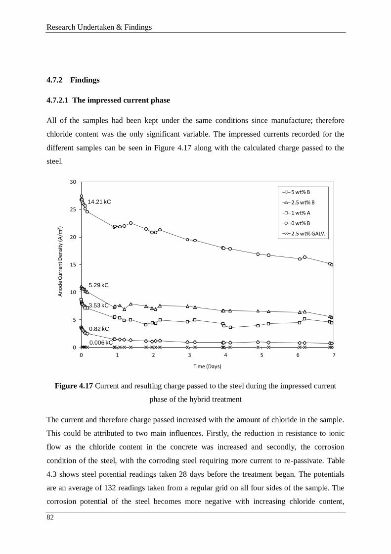
Research Undertaken & Findings
82
4.7.2 Findings
4.7.2.1 The impressed current phase
All of the samples had been kept under the same conditions since manufacture; therefore
chloride content was the only significant variable. The impressed currents recorded for the
different samples can be seen in Figure 4.17 along with the calculated charge passed to the
steel.
Figure 4.17 Current and resulting charge passed to the steel during the impressed current
phase of the hybrid treatment
The current and therefore charge passed increased with the amount of chloride in the sample.
This could be attributed to two main influences. Firstly, the reduction in resistance to ionic
flow as the chloride content in the concrete was increased and secondly, the corrosion
condition of the steel, with the corroding steel requiring more current to re-passivate. Table
4.3 shows steel potential readings taken 28 days before the treatment began. The potentials
are an average of 132 readings taken from a regular grid on all four sides of the sample. The
corrosion potential of the steel becomes more negative with increasing chloride content,
0
5
10
15
20
25
30
0 1 2 3 4 5 6 7
An
od
e C
urr
ent D
ensi
ty (
A/m
2)
Time (Days)
5 wt% B
2.5 wt% B
1 wt% A
0 wt% B
2.5 wt% GALV.
14.21 kC
5.29 kC
3.53 kC
0.82 kC
0.006 kC

Research Undertaken & Findings
83
indicating that the chloride level in the concrete affects the corrosion occurring. Figure 4.18,
which plots chloride content against charge passed suggests that the amount of chloride in the
concrete has a more linear relationship with the current passed whereas the effect of further
additions of chloride has a diminishing effect on the corrosion reaction (Figure 4.19) which
may also be limited by other factors such as moisture availability at the steel surface.
Table 4.3 Average steel potentials prior to the hybrid treatment
Block name
Average potential reading prior to
hybrid treatments (mV vs. SCE)
0 wt% A -72
0 wt% B -136
1 wt% A -255
1 wt% B -361
2.5 wt% A -498
2.5 wt% B -537
2.5 wt% C -517
5 wt% A -557
5 wt% B -452
Figure 4.18 The relationship between concrete chloride content and charge passed to the steel
during the impressed current phase of the hybrid treatment
0
2
4
6
8
10
12
14
0 0.5 1 1.5 2 2.5 3 3.5 4 4.5 5
Ch
arge
pas
sed
(kC
)
Concrete chloride content (% by weight cement)

Research Undertaken & Findings
84
Figure 4.19 The relationship between concrete chloride content and steel potential prior to the
impressed current phase of the hybrid treatment
It is clear from Figure 4.20 that the impressed current treatment has a lasting effect on the
current output of the hybrid anode and its response to changes in environmental conditions. A
purely galvanic block containing 2.5 wt% chloride by weight of cement had a similar current
output to that of a block with no mixed-in chloride that had undergone the impressed current
treatment (Figure 4.20). Removing the impressed current treatment also has a huge influence
on the charge that an anode is able to pass. A 2.5 wt% chloride galvanic block which had not
received any impressed current passed 17.6 C during a 29 day period. A block that had
received the treatment passed 143.1 C during the same period some 11 months after the initial
treatment.
-600
-500
-400
-300
-200
-100
0
0 0.5 1 1.5 2 2.5 3 3.5 4 4.5 5
Stee
l Po
ten
tial
(m
V v
s. S
CE)
Concrete chloride content (% by weight cement)

Research Undertaken & Findings
85
Figure 4.20 Anode current density comparison of anodes that had/had not received the
impressed current phase of the hybrid treatment after approximately 10 months in galvanic
mode
4.7.2.2 The galvanic phase
The experimental arrangement resulted in the indoor samples receiving no moisture (from
rainfall) and being exposed to higher daytime temperatures as a result of the indoor
conditions. This allowed comparison of blocks with the same chloride content exposed to
different wetting regimes, whereas the investigation to date had focused on either the effect of
chloride content or concrete moisture content.
A detailed discussion of the results can be found in Paper 3 (Appendix D), but the effect is
illustrated quite succinctly in Figure 4.21 which examines the effect of moisture on the
amount and degree of current response. Figure 4.21 shows that the outdoor 0 wt% and 2.5
wt% chloride blocks delivered ~4 and 2.5 times more current than the equivalent indoor
blocks respectively due to the higher moisture content. Similar trends were observed for the 1
and 5 wt% chloride blocks, even though the indoor temperature was significantly higher than
the outdoor temperature (Figure 4.22) during the day. This highlights the dominant influence
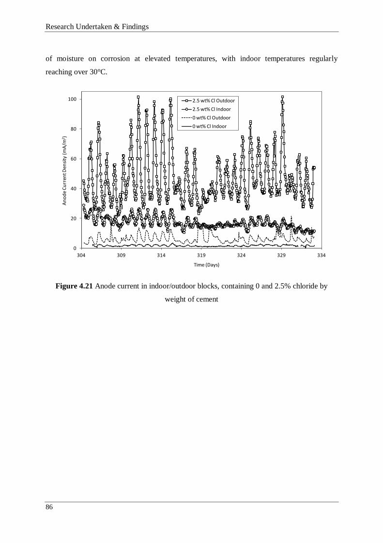
Research Undertaken & Findings
86
of moisture on corrosion at elevated temperatures, with indoor temperatures regularly
reaching over 30°C.
Figure 4.21 Anode current in indoor/outdoor blocks, containing 0 and 2.5% chloride by
weight of cement
0
20
40
60
80
100
304 309 314 319 324 329 334
An
od
e C
urr
ent D
ensi
ty (
mA
/m2)
Time (Days)
2.5 wt% Cl Outdoor
2.5 wt% Cl Indoor
0 wt% Cl Outdoor
0 wt% Cl Indoor

Research Undertaken & Findings
87
Figure 4.22 Fluctuations in indoor and outdoor air temperature
To explain the interaction of the three variable factors (moisture level, temperature and
concrete chloride content), a simple model was introduced which related changes in the
concrete environment to that of variable resistors operating within Ohm’s law (Figure 4.23).
This formed a convenient method of discussing the fluctuations in current output when
concrete samples are placed in different environmental conditions.
0
5
10
15
20
25
30
35
40
45
304 314 324 334
Air
Tem
per
atu
re (°
C)
Time (Days)
Indoor
Outdoor

Research Undertaken & Findings
88
Figure 4.23 Variable resistance of concrete in a galvanic cell, represented by three variable
resistances simulating the contributing concrete conditions
The three “variable resistances” shown in Figure 4.23 and their interaction formed the basis
for the experimental and sample designs used in the investigations detailed in Papers 2 and 3
(Appendices C and D).
4.8 TASK 5 - ZINC/STEEL ANODE SAMPLE – SAMPLE SET 5
Prior to this point in the investigation, the work had focused on analysing the anode response
to environmental changes, without any attention being paid to the response of the embedded
steel to the same changes. The aim of this phase of the investigations was to record both the
zinc and steel response to environmental conditions using a single specially designed sample
(Figure 4.24), and in doing so discuss the relationship between the steel corrosion risk and the
response of the protective current to that risk.
4.8.1 Research method
The sample was designed such that the zinc anode represented a galvanic anode installed in
contaminated concrete and the steel anode represented a section of corroding steel rebar that
the zinc anode was designed to protect. The steel bar was installed to provide a common
cathode for the anodes to pass galvanic current to, allowing independent measurement of both

Research Undertaken & Findings
89
currents. The current density recorded for the steel anode gives an indication of the amount of
corrosion activity occurring on the steel bar and represents the steel corrosion risk, whilst the
zinc anode galvanic current represents the protective current. Sample construction details can
be found in Paper 4 (Appendix E). Using this simple model in combination with the literature
review presented in Section 2.1, a discussion is opened regarding the steel protection criteria
governing buried steel in atmospherically exposed concrete.
Figure 4.24 Embedded zinc and steel anode block; (a) side elevation, (b) plan
Current data was collected every 6 hours for 77 days (Figure 4.25), and allowed the zinc and
steel current response to temperature and rainfall to be measured simultaneously for the first
time.
4.8.2 Research findings
From the data presented in Figure 4.25 it can be seen that both the zinc and steel anode
respond to changes in temperature and moisture brought about by rainfall. This is especially
apparent when there is a long period of dry weather between days 49 and 67 where daily
temperature fluctuations are the main influence on the current passed.
120
120
50
90
600
Steel Rebar
Zinc Anode
Cl- Contaminated Mortar
Bulk Concrete
Steel Anode
a)
b)

Research Undertaken & Findings
90
Applying the model proposed in Figure 4.23, it can be seen that the cathodic current passed
by the zinc anode (protective current) responds proportionally to the corrosion risk,
represented by the steel anode current, passing more current when the environment at the steel
is aggressive and less when the environment is benign.
Figure 4.25 Zinc and steel anode current response to rainfall and changes in temperature
The ratio of zinc to steel galvanic current was seen as a convenient way of expressing the
amount of protection offered to the steel by the zinc. When the ratio is large, the zinc offers
more protective current than when the ratio is small. From Figure 4.26, it can be seen that the
protection offered to the steel increases when the environment becomes more aggressive.
When it rained on day 67, it appeared that the zinc anode responded more rapidly than the
steel anode to the large increase in corrosion risk Figure 4.26. This meant that the protective
current was greatly increased prior to any increased demand from the steel. The disparity in
the anode response means that there is a dramatic increase in the ‘protective ratio’ (the
difference between the zinc and steel current output) and therefore the amount of protection

Research Undertaken & Findings
91
offered by the zinc. As the steel corrosion risk increased, the ratio stabilised at a more typical
level.
Figure 4.26 The zinc and steel anode current density response to sudden rainfall and the
resulting effect on the protective ratio.
In Papers 2, 3 and 4 (Appendices C – E) the data presented is discussed in terms of the two
main protection criteria applied to steel in concrete; the pitting potential/re-passivation
potential hypothesis and the pit re-alkalisation/pH maintenance hypothesis. A literature
review formed a significant part of this work and as a result these hypotheses and their bases
are discussed extensively in Sections 2.2 and 2.3 and in Glass et al (2008). It is felt that a
summary of the points discussed would be pertinent at this juncture:
o Impressed current systems suppress responsive behaviour in order to achieve the 100
mV polarisation criteria. The 100 mV criteria is unnecessary in some cases as over
time the cathodic current will reduce the aggressivity of the environment at the
steel/concrete interface by increasing the alkalinity and removing chloride ions. In
doing so, this raises the pitting potential of the steel, and reduces the need for
0
2
4
6
8
10
12
0
100
200
300
400
500
600
700
66.0 66.5 67.0
Ra
tio
of Z
inc/S
tee
l Cu
rre
nt D
en
sitie
s
Cu
rren
t Den
sity
(mA
/m2 )
Time (Days)
Zinc
Steel
Ratio
AggressiveBenign

Research Undertaken & Findings
92
polarisation and means that the concept of adequate polarisation is determined by
hydroxide generation and/or chloride removal.
o The pit re-alkalisation/pH maintenance hypothesis allows full utilisation of responsive
behaviour because when the environment is aggressive and the steel corrodes,
protective current is passed to restore a high pH at the steel surface or prevent local pH
reduction, whereas in benign environments no current is required to generate
hydroxide or re-alkalise corroding pits but the steel is still adequately protected.
o Revisions to the European standard which consider the present risk of steel corrosion
by considering the corrosion current resulting from the relative aggressivity of the
concrete environment would be more valid in their application.
o A cathodic protection system based on the concepts of pit re-alkalisation and pH
maintenance can fully utilise galvanic anode responsive behaviour.
4.9 SUMMARY
This section presented the details of the tasks undertaken to meet Objectives 3, 4, 5 and 6. The
conclusions drawn from these are discussed in Chapter 5.
4.10 TITANIUM FEEDER WIRE DETERIORATION – PART 3
This section of the thesis will detail the work completed to achieve Aim 3 – “Investigate the
causes of the on-site deterioration of commercially pure titanium feeder wire and investigate
methods of protecting against it”. This section of the research was applied in nature, in that it
aimed to solve a potential problem that was specific to a material, product and set of
conditions. It did not seek to add significant matter to ongoing academic debates regarding the
mechanisms of the anodic behaviour of titanium, but rather to identify the mechanisms
causing the defects and investigate methods to nullify or reduce their impact. This work was
not written up elsewhere and so the following section includes significant discussion as well
as the findings of the investigation.
This work has been added to the thesis due to the significant impact on the sponsor company
and their products.

Research Undertaken & Findings
93
4.10.1 Preliminary studies
Following the discovery of areas of deterioration on the commercially pure titanium wire on
site, a literature review was undertaken to discover the causes of the effect seen (Section 2.6).
This led to a greater understanding of:
1. The corrosion resistance of titanium in a range of aggressive media.
2. The conditions required for titanium corrosion under anodic polarisation.
and following the identification of anodising as a potential solution to the risk of titanium
pitting, investigations were prompted into:
3. The steps required to grow a consistent and structured oxide on the surface of the
titanium
4. The effect of process parameters on the resultant grown oxide.
5. The ability of anodic oxides to protect against corrosion in aggressive media.
The following section presents a series of tasks aimed at investigating points 3 to 5 above.
4.11 TASK 6 – IDENTIFY THE CAUSE OF WIRE DETERIORATION
4.11.1 Research method
Following the collection of samples from site, visual assessment alongside anecdotal evidence
and a thorough literature review was used to uncover the cause of the defects seen.
4.11.2 Research findings
Figure 4.27 shows characteristic deterioration of the CP titanium taken from a site in the UK.
There did not seem to be any change in the texture of the wire although the colour of the wire
had changed from silvery to gold/brown in the areas that were in contact with the concrete
surface before gradually returning to the colour of the native oxide. Figure 4.27 shows a
photograph of a sample displaying the effect.

Research Undertaken & Findings
94
Figure 4.27 An example of the deterioration seen on CP titanium wire installed on a site in
the UK
From informal conversations held with CPT staff and contractors on site, the following
anecdotal evidence was gathered:
1. In all cases, the concrete surrounding the site of the deterioration had been damp, if
not wet.
2. No short circuits (potential source of heat) were reported from any of the sites and
commissioning checks suggest that no short-circuits were present in the installed
anode zones.
3. All of the patches of deterioration reported were discovered during or immediately
after the impressed current phase of the treatment (12V applied current).
4.11.3 Discussion
The lack of a heat source ruled out a thermal cause of the defects. The nature of the defect and
the fact that the wire was under significant anodic polarisation in the presence of moisture
indicated an electrochemical process. The literature review carried out at this stage revealed
that titanium is susceptible to corrosion in the presence of chlorides (and other halides) under
anodic polarisation (See Section 2.6). Chloride is commonly present at the location of
cathodic protection installations as it is one of two aggressive conditions that lead to steel

Research Undertaken & Findings
95
corrosion and the requirement for a cathodic protection system (please refer to Section 2.3.1
for further details). Corrosion normally takes the form of pitting, which leads to localised loss
of material at sites of weakness on the titanium surface (such as grain boundaries or surface
imperfections). As discussed in Section 2.6, the pitting potential of titanium in chloride
solutions under anodic polarisation is between 8 and 14 V.
The brown/gold deterioration surrounding the defect is typical of the interference colours
caused by oxide growth during DC anodising. As anodising can be undertaken in any ion-
containing liquid, it is likely that the oxide growth was as a result of the anodic polarisation in
liquid containing chloride ions (Section 2.7). Anodising of titanium is known to increase the
pitting resistance of titanium in aggressive media (Section 2.7.7). Following a review of the
literature it was discovered that although the oxide growth in response to contact with
moisture would initially have a protective effect, at some critical potential (the pitting
potential) the oxide layer would break down due to the presence of chloride, and pitting
corrosion would be initiated.
4.12 TASK 7 – INVESTIGATE THE CONDITIONS LEADING TO
DETERIORATION
Polarisation data was collected at various distances from the installed anode in concrete
samples containing a variety of chloride levels, in order to assess the pitting risk between
installed hybrid anodes during the impressed current phase of the treatment.
4.12.1 Research method
The samples (containing either 0, 1, 2.5 or 5% chloride by weight of cement) used in the
study are described in Paper 3 (Appendix D), as they were also used for the responsive
behaviour work detailed in Section 4.7. Markings were made along the side of the saw-cut at
50 mm intervals to allow consistent measurement of the anode/wire potential using a high
impedance voltmeter and a manganese dioxide reference electrode. A steel connection was
made using a crocodile clip onto the titanium wire.
4.12.2 Research findings
Figure 4.28 illustrates the different anode potential gradients measured along several blocks
recorded on the same day. Potential measurements along the blocks were also made on days

Research Undertaken & Findings
96
1, 3 and 7 of the 7 day impressed current treatment to assess the shifts in potential during the
treatment period (Figure 4.29)
Figure 4.28 Titanium wire potential measurements at various distances along the block from
the anode (0 mm) on the second day of the impressed current phase
-9.00
-8.00
-7.00
-6.00
-5.00
-4.00
-3.00
-2.00
-1.00
0.00
0 100 200 300 400 500 600
Wire
po
ten
tia
l vs. S
CE
(V
)
Distance from anode (mm)
0 wt% A
0 wt% B
1 wt% A
1 wt% B
2.5 wt% A
2.5 wt% B
5 wt% A
5 wt% B

Research Undertaken & Findings
97
Figure 4.29 Titanium wire potential changes over the course of the 7 day DC current
treatment in a sample containing 2.5 wt% chloride
As can be seen from Figure 4.28 the chloride level in the blocks had an effect on the potential
gradients seen, although the decay as the reference electrode was moved away from the anode
was similar for all of the blocks, falling quite rapidly before reaching a steady state between
250 and 350 mm from the anode. Figure 4.29 shows that the wire potential moved to more
passive values as the treatment continued. This effect was especially pronounced close to the
anode.
4.12.3 Discussion
In order for pitting corrosion to propagate, the potential difference between the surface of the
concrete and the wire would have to exceed and remain above the pitting potential for the
titanium in the specific electrolyte. In a cathodic protection system employing point anodes,
this potential will change between the installed anodes, due to the difference between the wire
potential and the voltage at which the steel is subjected to under the impressed current. This
difference will increase as the anode’s effect diminishes. The concrete acts as a conductive
-9.00
-8.00
-7.00
-6.00
-5.00
-4.00
-3.00
-2.00
-1.00
0.00
0 100 200 300 400 500 600
An
od
e p
ote
nti
al (
V v
s. S
CE)
Distance from anode (mm)
Day 7
Day 3
Day 1

Research Undertaken & Findings
98
path from the steel to the titanium, thus effectively conveying the potential difference from
the steel surface to the titanium when it comes into contact with it.
This effectively means that the risk of surpassing the pitting potential of the titanium increases
with distance from the installed anode. This can be seen in the data presented in Figure 4.28
and 4.29 and is explained graphically in Figure 4.30. Although anodes in a site installation
would not be spaced more than 500 mm apart, it seems that there is still a risk of corrosion to
a significant section of wire either side of the mid-span where the pitting potential will be
above 9V.
Figure 4.30 The potential difference between the titanium wire and the steel as a function of
distance from the anode. Anode located at 0 mm
From the results presented in Figure 4.29, it can also be seen that the closer that the end of the
impressed current treatment phase becomes, the greater the pitting risk in areas close to the
anode due to an increase in the pitting potential difference. Figure 4.31 is a model version of
the effect presented in Figure 4.29. If, for example, 10.6V is the pitting potential of the wire,
then as time progresses, the distance from the anode at which the pitting potential difference
is below 10.6 V is diminished.
Distance from anode (mm)
Po
ten
tial
vs.
SC
E (V
)
Wire potential
0
6V
-12
9V 11V
Steel voltage
Wire voltage
DC
Vo
ltage (V)
0
-12
0 500

Research Undertaken & Findings
99
This is a result of a positive shift in the potential of the anode and the connected titanium
wire, which is likely to have been caused by the continuing anode polarisation and the build-
up of corrosion products at the anode surface. The change is greatest close to the anode and
diminishes with distance from it.
Figure 4.31 The positive shift in the wire potential throughout the course of the treatment (for
illustrative purposes)
4.13 TASK 8 – INVESTIGATION OF ANODISING PRE-TREATMENTS and
ANODISING PARAMETERS
Following on from investigations into the causes of the deterioration and pitting risk, potential
solutions to the pitting issue were discussed. A literature review followed (Section 2.7.7),
which identified the barrier qualities of an anodically grown oxide as a possible way to reduce
or eliminate the risk of pitting.
Little research had been completed to assess the extent to which an anodised coating could
increase the corrosion resistance of titanium under anodic polarisation in halide media. It was
-1.4 -1.6
-1.9
Mix
ed
po
ten
tia
l vs. S
CE
(V
) Effe
ctiv
e p
itting
po
ten
tial (V
)
-0.9 11.1
10.610.4
10.1
Distance from anode (mm)
Day 1
Day 3Day 7
1500 500

Research Undertaken & Findings
100
postulated that anodising could delay the onset/reduce the risk of pitting in susceptible areas
of the installed anode system.
An investigation commenced which aimed to examine:
1. The requirements (pre-treatments, treatment times, solution strengths) for growing a
suitable oxide on the titanium substrate
2. The characteristics of the grown film (morphology, porosity, thickness)
3. The ability of the grown oxide to protect the titanium substrate from pitting corrosion
in chloride solutions
It was decided that it would be best to focus on one anodising solution initially whilst
becoming familiarised with the technique. Sodium hydroxide (NaOH) was chosen due to its
ease of handling and the fact that alkaline solutions are used to generate thick anti-galling
coatings and surfaces which increase adhesion in metal to metal bonding (Kennedy et al
1983) whereas acid anodising is generally used to create thin decorative coatings and for
substrate preparation prior to adhesive bonding due to the porous structures generated
(Donachie 1988).
4.13.1 Research method
Commercially pure titanium wire was cut into ~90 mm sections and then cleaned in an
ultrasonic acetone bath for 5 minutes to degrease before being rinsed in distilled water and
dried. The samples were then pickled for 2 minutes in a bath containing 1% hydrofluoric acid
(HF) and 15% nitric acid (HNO3) made with de-ionised water (Section 2.7.4). Following
pickling, the titanium was rinsed in distilled water and dried.
To assess the effect of the de-oxidising treatment on the growth and integrity of the anodised
layer 3 samples were grown at both 16 and 24V (6 in total) without the pickle stage.
An austenitic stainless steel plate 40 x 120 x 4 mm was used as the counter electrode and a
submerged 80 mm length of wire as the working electrode. The plate was cleaned with liquid
detergent and water before being rinsed in tap water, and wiped with acetone. Both electrodes
were connected to the power supply by a crocodile clip and sheathed copper wire. An
ammeter was placed in series with the anode to measure the current during the treatment

Research Undertaken & Findings
101
A magnetic stirrer was used to agitate the solution (0.2 Molar NaOH in distilled water) and a
thermometer positioned close to the titanium. A schematic of the anodising arrangement can
be seen in Figure 4.32.
Figure 4.32 Schematic of anodising experimental arrangement
The power was turned on and an instantaneous current reading was taken. The titanium was
then left to anodise for 2 minutes before the power was turned off. Just before the current was
turned off a final current reading was taken.
Samples were anodised at 4, 8, 12, 16, 20, 24 and 28V, with three samples made for each
voltage in separate experiments.
4.13.2 Research findings
Table 4.4 describes the anodising voltage and coating colour achieved as well as measured
experimental parameters.
+
0.2 M NaOH
solution
Ti wire
Stainless steel plate
Thermometer
Magnetic stirrer
A

Research Undertaken & Findings
102
Table 4.4 Colour, current and temperature data for titanium samples anodised with and
without the de-oxidising treatment
Formation voltage
(V) and Sample
no.
Colour
achieved
Start
Current
(µA)
End
Current
(µA)
Temperature
(°C)
Time to
end current
(seconds)
4a
4b
4c
Light Gold
2.0
2.3
4.7
0.1
0.1
0.1
21.2
21.2
21.2
7
6
7
8a
8b
8c
Gold
3.0
6.1
4.2
0.1
0.1
0.3
21.5
21.7
21.8
6
5
5
12a
12b
12c
Maroon
2.0
5.4
3.0
0
0
0
23.8
24.0
24.1
8
11
10
16a
16b
16c
Deep
purple/blue
3.3
1.7
2.0
0
0
0
23.0
23.3
23.5
10
13
13
20a
20b
20c
Royal Blue
5.8
9.6
5.0
0
0
0
24.2
24.2
24.2
11
12
12
24a
24b
24c
Light Blue
2.5
2.0
2.2
0
0
0
24.2
24.2
24.4
12
14
12
28a
28b
28c
Pale Blue
5.6
4.0
3.7
0.5
0
0.1
24.5
24.5
24.6
11
10
10
Un-pickled samples
16a
16b
16c
Muddy dull
purple/blue
17
23
9.4
1.5
1.9
1.4
24.8
24.8
24.8
-
-
-
24a
24b
24c
Muddy
grey/purple
17
19.1
14.9
1.8
1.3
2.6
24.8
24.8
25.0
-
-
-
The titanium wire pre-treatments appeared to strip the native metal oxide and associated
contaminants. Even though the samples were anodised in separate experiments, the colours
Research Undertaken & Findings
103
achieved at the different voltages for the pickled samples were very consistent. This would
indicate that the oxide layer was of a similar thickness on all areas of the samples when the
applied voltage was constant.
For the majority of the samples anodised, the current measured on the ammeter dropped to a
zero (as determined by the sensitivity of the multimeter used) within 14 seconds of the start of
the procedure, with the lower voltages showing shorter times.
The samples which did not receive the de-oxidising treatment were very different in colour to
the samples which did, and the colour was much less uniform over the surface.
4.13.3 Discussion
The rapid reduction in current would suggest that the film formation was substantially
completed within this time and has been noted by other authors (Wu et al 2009). It has been
suggested (Aladjem 1973) that the decrease in current seen can be attributed to the increase in
film thickness causing greater surface resistance, a gradual decrease in the concentration of
Ti3+
ions in the film or increasing film perfection. In either case, the net effect is an increase
in the apparent resistivity of the grown oxide leading to a dramatic slowing in film growth, an
effect noted by Sul et al (2001).
There was a general change in colour of the wire samples that did not receive the pickle pre-
treatments and the colour varied over the surface. In some areas the native oxide was clearly
visible where no or only small amounts of growth had occurred. This was especially visible in
the ‘wake’ of the wire created by the stirrer, where bubbles appeared on several of the
samples. The bubbles were not observed on the pickled samples, indicating that they had a
much lower surface energy than the un-pickled titanium. Unlike the pickled samples, there
was still significant current being passed to the wire at the end of the treatment time. This
indicated that film formation was incomplete and that the existing film had a low level of
perfection.
4.14 TASK 9 – ANALYSIS OF THE GROWN OXIDE LAYER
Task four is broken down into two sub-tasks. Sub-task one examines the microscopy of the
grown oxides and sub-task two examines their electrochemical properties.

Research Undertaken & Findings
104
4.14.1 Sub-task 1 – The microscopy of anodised titanium
In order to examine the structure of the grown oxide layer and determine a voltage/thickness
relationship, scanning electron microscopy was used to characterise the surface of the wire.
4.14.1.1 Research method
The anodised samples created at 4, 8 and 16V using the process described in Section 4.13.1
were ultrasonically cleaned for 5 minutes before being dried. They were then bent through
180° at room temperature to rupture the oxide film on the outer surface, before being mounted
on conductive carbon stubs using silver paint. The samples were then gold sputtered for ~1
minute to increase the conductivity of the oxide and reduce charging in the electron beam.
A field emission gun scanning electron microscope (FEGSEM) in secondary electron imaging
mode was used to examine the oxide film and assess its morphology and thickness at the
different formation voltages. The beam energy was 5kV throughout the analysis. Scanning
electron microscope images can be seen in Figures 4.33 to 4.35.
4.14.1.2 Research findings
All of the anodic oxides formed appeared to have similar characteristics, with the fractured
oxide having the appearance of an applied coating and the native oxide being clearly
distinguishable from the anodised layer (Figure 4.33). The film appeared to be compacted and
had little porosity even at a relatively high magnification. Afshar and Vaezi (2003) noted
similar oxide characteristics, albeit in a much stronger solution. The bending technique had
the desired effect of rupturing the film at room temperature.
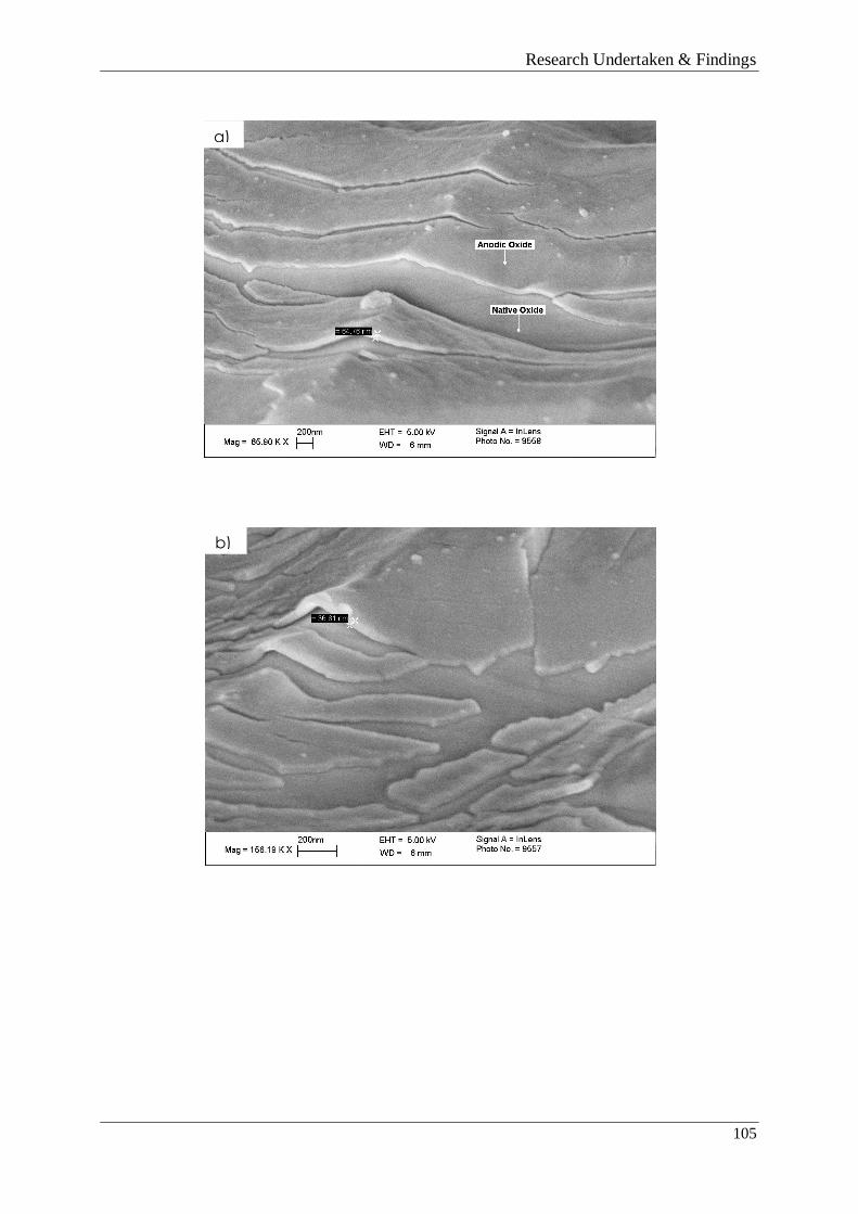
Research Undertaken & Findings
105
a)
b)
))

Research Undertaken & Findings
106
Figure 4.33 High magnification secondary electron SEM images of the NaOH anodised
surfaces; a) 4V; b) 8V; c) 16V
Figure 4.34 General surface topography of the 8V NaOH anodised titanium
c)
))

Research Undertaken & Findings
107
Figure 4.35 ‘Rucking’ surface characteristic seen on the 8V NaOH anodised titanium
4.14.1.3 Discussion
The grown oxide is divided by very clean fractures (Figure 4.33), seemingly revealing the
native oxide beneath. The measuring tool made it possible to attain the oxide thicknesses for
each sample. It would be expected that the higher the treatment voltage, the thicker the oxide,
however this was not the case, with the 4 and 16V samples which showed similar thickness
layers. These results are at odds with the different colours generated by the treatments which
suggest increased thickness with applied voltage (Sul et al 2001, Afshar and Vaezi 2003). It is
possible that the measurements made are of an oxide composed of the native oxide as well as
the grown oxide layer. More thickness measurements may have shown a clearer relationship
and this result is likely to be erroneous.
General deformation of the titanium can be seen in Figure 4.34, whilst an interesting effect on
the grown oxide can be seen in Figure 4.35. This ‘rucking’ of the layer and its peeling away in
the other images questions the strength of its adhesion to the titanium, albeit under extreme
tensile stresses caused by the bend.
4.14.2 Sub-task 2 - Potentiodynamic polarisation of anodised titanium wires
In order to quantify any protective effect imparted by the grown oxide layer, potentiodynamic
polarisation experiments were undertaken in both chloride and bromide media.

Research Undertaken & Findings
108
4.14.2.1 Research method
A section of 30 mm long titanium (un-anodised, 6, 12 or 24V) prepared in the same manner
as those described in Section 4.13.1 was immersed in the electrolyte to form the working
electrode. A section of platinised titanium mesh (20 x 20 mm) formed the counter electrode
and a SCE was used as the reference electrode. An EG & G potentiostat with attendant
Powersuite software was used to increase the potential of the working electrode at 10
mV/second until 5V was reached. The resultant change in current was recorded and plotted
against the working electrode potential to generate polarisation curves (Figure 4.36). Five
scans each were completed for wires anodised at 0, 6, 12 and 24V in 1 M potassium bromide
(KBr) and sodium chloride (NaCl) solutions made with deionised water. The scan rate of 10
mV/s was taken from the work of Fattahi and Shariat (2008).
4.14.2.2 Research findings
Polarisation curves for commercially pure titanium in 1 M KBr generated for the un-anodised
and wires anodised at 6, 12 and 24V can be seen in Figure 4.36. The Figure contains one scan
from the four carried out that best represented each anodising voltage. It can be seen in Figure
4.37 that wires anodised at the same voltages exhibited range of pitting potentials this is most
likely due to the nature of pit initiation (Section 2.6), although the scan features were broadly
the same. Experiments were also carried out using 1 M NaCl but it was not possible to pit the
titanium using the available potentiostat as the limiting potential for the device was 10V and
the pitting potential was above 10V in this case.
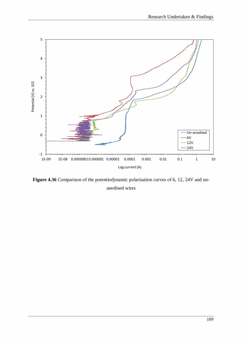
Research Undertaken & Findings
109
Figure 4.36 Comparison of the potentiodynamic polarisation curves of 6, 12, 24V and un-
anodised wires
-1
0
1
2
3
4
5
1E-09 1E-08 0.00000010.000001 0.00001 0.0001 0.001 0.01 0.1 1 10
Po
ten
tial
(V) v
s. S
CE
Log current (A)
Un-anodised
6V
12V
24V

Research Undertaken & Findings
110
Figure 4.37 Potentiodynamic polarisation of 6V anodised titanium wire in 1 M KBr solution.
Anodising the wire to create grown oxides of different thicknesses did not increase the pitting
potential of the commercially pure titanium. Pitting potentials varied between 1.7 and 4V,
with the 6V anodised wire showing the highest pitting resistance overall. Average pitting
potentials can be seen in Table 4.5. The current at the pitting potential ranged by an order of
magnitude from 0.0001 to 0.001A but again was un-related to oxide thickness.
The rest corrosion potential of the anodised wires at all anodising voltages was significantly
more passive than the un-anodised wires, indicating a lower corrosion rate in the bromide
solution. The average rest potentials of the wires can be seen in Table 4.5.
-1
0
1
2
3
4
5
1E-09 1E-08 0.0000001 0.000001 0.00001 0.0001 0.001 0.01 0.1 1 10
Po
ten
tial
(V) v
s. S
CE
Log current (A)

Research Undertaken & Findings
111
Table 4.5 Pitting potentials and rest potentials as a function of anodising voltage
Anodising voltage (V) Average pitting potential
(V) vs. SCE
Average rest potential (V)
vs. SCE
Un-anodised 2.28 -0.522
6 3.22 -0.216
12 1.90 -0.241
24 2.33 -0.277
4.14.2.3 Discussion
The ‘shape’ of the un-anodised and anodised wire polarisation scans was significantly
different (Figure 4.38). The un-anodised wire entered the active corrosion region almost as
soon as the scan commenced before transitioning into a very distinct passive region between
~-0.3 and +0.2V as corrosion products built up on the electrode surface. This passive region
gave way to corrosion between 0.9 and 1V as the layer of corrosion products began to break
down. Pitting corrosion began between 1.7 and 2.9V as the protective oxide was stripped.
In contrast, the scans representing the anodised titanium started with a metastable passive
region which persists from the rest potential until ~1V. In all cases, the metastable passive
region gave way to an active region which ended in a passive region or region of reduced
corrosion before pitting set in between 1.7 and 4V. It is thought that the intervening period
between corrosion initiation and passivation was due to general corrosion of the grown oxide
before corrosion products building on the surface led to an increasingly passive period. The
corrosion product layer and remaining oxide layer then broke down and pitting set in as the
dominant mechanism.
Growing an oxide on the surface of the titanium had the effect of delaying the onset of
corrosion to higher potentials. The anodised wires all displayed a metastable passive area
from the rest potential to >800 mV where generalised corrosion began, whereas the un-
anodised wire current increased almost from the rest potential.
The recorded pitting potentials for anodised titanium samples in the bromide solution were
within the range of results (1.1-4.5V) previously reported for un-anodised titanium (Table

Research Undertaken & Findings
112
4.6). The variation in results can to some degree be attributed to experimental parameters such
as solution agitation and aeration, scan rate and temperature, however several workers have
also noted the large variation in pitting potential whilst using material and solution of the
same purity (Trompette et al (2011) and Hoar (1967)). The variation in pitting potentials
would then appear to be surface specific and dependent on grain boundaries, impurities and
areas of oxide thinning. Although the growth of an anodic oxide did not significantly affect
the pitting potential, the variation in pitting potential decreased with increased anodising
voltage. The standard deviations of the pitting potentials of un-anodised and 6, 12 and 24V
anodised wires were 0.601, 0.626, 0.315 and 0.09 respectively. This can be attributed to
increased consistency and order in the structure of the oxide as it increases in thickness. This
shows that although anodising in this electrolyte and in this voltage range does not increase
the pitting potential, increased oxide thickness dramatically reduces the range of pitting
potentials seen.
Table 4.6 Commercially pure titanium pitting potentials and the solution strengths used in
potentiodynamic polarisation experiments by different authors
Authors Measured Pitting potential
(V)
Solution used and strength
(M)
Dugdale and Cotton (1964) 3.5 1M KBr
Sazou et al (2012) 3.9 - 5.5 0.25 - 1M KBr
Trompette et al (2011) 1.6 0.1M KBr
Fattahi and Shariat (2008) 1.1 – 1.5 0.1M KBr
Virtanen and Curty (2004) 2.5 – 4.5 1M KBr
4.15 SUMMARY
This section presented the details of the tasks undertaken to meet Objectives 7, 8 and 9 as
discussed in Chapter one.
Following the initial investigations detailed in this section, the sponsor company opted to
replace un-coated CP titanium feed wire with a cross-linked polyethylene (XLPE) coated

Research Undertaken & Findings
113
version of the same material. This had the effect of insulating the wire from the environment
at the concrete surface and removing the pitting risk.
4.16 SECTION SUMMARY
This chapter presented the details of the six tasks undertaken to meet the research aims and
objectives set out in Chapter 1. The conclusions drawn from these are discussed in Chapter 5.

Conclusions
114

Conclusions
115
CHAPTER 5 - CONCLUSIONS
This chapter presents the key conclusions from the research along with their impact on the
research sponsor and the wider industry. The research path and its outcomes are then critically
evaluated following which recommendations for future research are made.
5.1 KEY RESEARCH CONCLUSIONS
5.1.1 Corrosion characterisation – Aim 1
This work was completed in order to achieve Aim 1: “Characterise the electrochemical
processes occurring in laboratory samples using common industry techniques”. In order for
the author to gain experience of corrosion assessment techniques, several experiments were
carried out with the aim of characterising the corrosion processes occurring on concrete
samples containing embedded hybrid anodes. In the case of Sample set 1, the testing took
place 2 and 4.5 years after the sample was cast. The main conclusions from the experimental
work completed to achieve Aim 1 were:
o A hybrid anode treatment regime was successful in halting steel corrosion and
maintaining passivity in a chloride contaminated concrete block for more than 4.5 years
(Sample Set 1). Steel passivity was confirmed by the low corrosion rate measurements
determined by both impedance analysis and de-polarisation experiments and was
indicated by the significantly more positive steel potential and slow steel depolarisation.
o Significant de-polarisation measured at the rear of the steel plate showed that the installed
sacrificial anode was able to adequately protect steel even when it was positioned in
difficult geometries.
o A short-term DC impressed current treatment (Sample Sets 1 and 2) caused a significant
positive shift in the steel potential when compared with the native steel potentials prior to
the treatment. This effect was evident in all of the chloride containing samples and
suggests the modification of the environment at the steel surface.
o An applied current which shifted the steel potential more than ~300 mV during the
impressed current phase was sufficient to cause a significant positive shift in the galvanic

Conclusions
116
mixed steel potential 500 mm from the anode following the removal of the impressed
current.
5.1.2 Responsive behaviour – Aim 2
This work was completed in order to achieve Aim 2: “Investigate the benefits of the
responsive current behaviour of cathodic protection systems and discuss with regards to
existing steel protection hypotheses and criteria”. The current passed to the steel by installed
hybrid/galvanic anode(s) was recorded and analysed in relation to concrete moisture content,
concrete chloride content and air temperature. Data was analysed from sample sets 3, 4 and 5.
The experimental design and the results of the investigation also informed a discussion
regarding the application of protection criteria applied to steel in atmospherically exposed
concrete and the theories behind these criteria. The key conclusions from the work were:
o The current passed by embedded hybrid/sacrificial galvanic anodes connected to
reinforcing steel in concrete responds rapidly to changes in corrosion risk brought about
by changes in temperature and concrete moisture and chloride content. In concrete
environments where the corrosion risk is high, more current is passed to the steel. In
concrete environments where the corrosion risk is low, less current is passed to the steel.
This is true of both the impressed current and galvanic current phases of the hybrid
treatment.
o Sacrificial anode lifetime is extended in benign environments where the corrosion risk is
low, meaning that their protective capacity is applied more efficiently. This has been
measured on site installations where the corrosion risk varies (Section 4.6) and in
laboratory samples exposed to different environmental regimes (Papers 2 and 3).
o It is postulated that the impressed current phase of the hybrid treatment ‘activates’ the
anodes, allowing them to deliver more charge than those that have not received the
treatment. It is thought that this is due to the migration of chloride ions to the anode,
aiding zinc oxidation.
o A basis for using the responsive behaviour of galvanic anodes is provided by the
protective effects of pit re-alkalisation and pH maintenance. In benign environments no
current is required to achieve pit re-alkalisation or maintain the pH, whilst in aggressive

Conclusions
117
environments current is required to either restore a high pH at the site of a pit or prevent a
local pH reduction and hence pit formation. The required protection current depends on
the present level of corrosion risk. By contrast, protection based on achieving adequate
polarisation inhibits the use of responsive behaviour and galvanic anodes might only
deliver adequate polarisation in aggressive environments.
The protection criteria presented in the European standard BS EN 12696 (2000) inhibits the
used of responsive behaviour. Revisions which consider the present risk of steel corrosion by
considering the corrosion current resulting from the relative aggressivity of the concrete
environment would add validity to their application.
5.1.3 Titanium feeder wire deterioration – Aim 3
This work was completed in order to achieve Aim 3: “Investigate the causes of the on-site
deterioration of commercially pure titanium feeder wire and investigate methods of protecting
against it”. Initial work examined the causes of discolouration seen on the surface of titanium
wire at hybrid anode installation sites before the conditions leading to the phenomena were
investigated. The process parameters of producing a protective anodic oxide on the surface of
the wire were then researched and wire samples anodised at different voltages were produced.
Finally, the characteristics of the grown oxides and their protective effects were examined.
The main conclusions from the work were:
o The brown/gold coloured discolouration on the surface of the titanium wire taken from
site is likely to be the result of anodising due to the anodic polarisation applied to the
wire and the presence of chloride. The colour is consistent with an anodising voltage of 8
to 12V.
o The titanium pitting risk increases with distance from the installed anode, meaning that
the highest risk on a site installation is the mid-point between two anodes. It is likely that
the pitting risk changes over the course of the treatment with the risk to the wire closest
to the anode increasing with time. This is due to the increasingly positive potential of the
anode.
o Anodising CP titanium in 0.1 M NaOH solution at room temperature produces a
compacted, non-porous oxide with the appearance of an applied coating.

Conclusions
118
o Anodising the wire in 0.1 M NaOH solution to create grown oxides of different
thicknesses did not increase the pitting potential of the commercially pure titanium in 1
M KBr solution, however, the rest potentials of the anodised samples was significantly
more positive, suggesting a lower corrosion rate than the un-anodised samples.
o Growing an anodic oxide on the surface of the titanium in 0.1 M NaOH solution had the
effect of delaying the onset of corrosion to higher electrode potentials in 1 M KBr
solution. The anodised wires all displayed a metastable passive area from the rest
potential to >800 mV where generalised corrosion began, whereas the un-anodised wire
current increased almost from the rest potential.
o The variation in pitting potentials decreased with increased anodising voltage. It is likely
that this can be attributed to increased consistency and order in the structure of the oxide
as it increases in thickness.
5.2 RESEARCH IMPLICATIONS AND CONTRIBUTION TO KNOWLEDGE
5.2.1 Corrosion characterisation
The research project has served to reinforce the observations of previous workers (Glass et al
2008) that the steel potential tends to more passive values in the galvanic treatment phase
following a short-term high current density treatment. This work contributes to the ongoing
discussion regarding the minimum polarisation requirement suggested in BS EN 12696 (2000
and 2012).
The work has had the effect of demonstrating a new, viable treatment methodology to the
cathodic protection industry. It has also proved that the treatment methodology is an effective
way of re-passivating corroding steel and providing ongoing corrosion protection.
5.2.2 Responsive behaviour
The research presented has helped to expand knowledge of the responsive of galvanic and
impressed current treatments to environmental factors, highlighting the practical impacts of
site conditions on anode system lifetimes. Data has been presented which shows responsive
current behaviour over the course of minutes, hours, days and months and also the response to

Conclusions
119
anomalous events. This has highlighted the consideration that must be given to the specific
conditions affecting a structure when designing a galvanic or hybrid protection system.
The work has proposed that suitably designed galvanic systems can be successfully applied to
a wider range of environmental conditions if responsive behavior is considered; not just the
aggressive environments required to achieve polarisation criterion.
The research undertaken has added significant matter to the ongoing debate regarding the
dominant protective effect imparted by the application of electrochemical treatments.
Although a significant proportion of the cathodic protection industry still explains the
protection imparted by cathodic protection systems in terms of steel polarisation and
advocates the use of polarization-based protection assessment methods, concessions to the
impact of other influences and the use of alternative assessment methods have been made in
recent publications. Both The Concrete Society Technical Report 73 (2011) and updated BS
EN 12696 (2012) suggest the use of the Butler Volmer equation in order to calculate the
corrosion rate of the steel as well as the 100 mV depolarisation criteria whereas their
predecessor documents did not. BS EN 12696 (2012) also states that “if the criteria for
protection are achieved (see Section 2.3.1), no further measures are necessary. If they are not
achieved with galvanic anode systems where it is not possible to increase current to the steel
then a further assessment of corrosion risk shall be made. If a corrosion risk is identified then
steps shall be taken to increase the protection current, by supplementing the galvanic anode
system, to minimize this risk.” This, along with other concessions in the document
demonstrates that consideration is now being given to the corrosion risk to the steel posed by
the environment that surrounds it, acknowledging that these will have a large bearing on the
steel de-polarisation and current achieved during system effectiveness testing.
5.2.3 Titanium feeder wire deterioration
To the author’s knowledge, this work represents the first attempt to characterise the influence
of a grown anodic oxide on the corrosion characteristics of CP titanium under anodic
polarisation. In addition, the relationship between interference colours and anodising voltage
is seldom seen in the literature and the data for the specific solution used has not been
published previously.

Conclusions
120
It has been shown that great care should be taken when using un-protected CP titanium under
anodic polarisation conditions when the applied voltage places sections of the wire in the
range of pitting potentials previously reported;
With significant future research, DC anodising may provide a cost-effective method for
protecting against titanium pitting in chloride media. This material could then compete in the
marketplace with mixed metal oxide coated titanium wire which is used heavily in the
cathodic protection industry.
5.3 IMPLICATIONS/IMPACT ON THE SPONSOR COMPANY
To contextualise the implications of the research it is important to note that unlike many
Research Engineers embarking on an Engineering Doctorate, the author joined a company
very much in its infancy, with only one product that had been installed in a handful of small
projects in the UK.
The work has generated four peer-reviewed papers which could be presented to potential
customers to explain the system function and its benefits over competitor products. Two of
these papers are referenced in sales literature. It is very unlikely that this research would ever
have been completed without the RE’s input.
The work has allowed CPT, through the Research Engineer and CICE, to publish matter on
the performance of their product systems at international conferences (Structural Faults and
Repair 2008, EuroCorr 2008, EuroCorr 2009, CORROSION 2011, Concrete Solutions 2011).
It has also allowed the demonstration of the capabilities of their anode systems and the ways
in which performance can be proven and monitored by the use of additional services supplied
by the company.
The EngD affiliation has allowed the sponsor company to complete significant research on
their own products, giving the directors a greater understanding of the market position of their
products, their strengths and their limitations. Work carried out by the RE has allowed the
sponsor company to make informed decisions regarding material use (replacement of bare
titanium with XLPE coated titanium), and maximum allowable anode spacing on site
installations (Section 4.3).

Conclusions
121
5.4 FUTURE WORK
5.4.1 Corrosion characterisation
Although this work primarily involved the assessment of corrosion activity, it also served to
ask questions of the methods used to determine corrosion rates. The disparity between the
corrosion rates recorded using different test methodologies is a potential area of interest and
has been noted in other studies by the author.
Work that measured the corrosion rate both before and after impressed current treatments of
various lengths, and correlated this data with the movement of the steel potential following
the treatment would be very interesting. Although a simple piece of work, to the author’s
knowledge, no such data has been published to date.
5.4.2 Responsive behaviour
In the latter stages of the research project the focus turned to the examination of responsive
behaviour with regard to the two theoretical hypotheses purporting to explain the protective
effect imparted by electrochemical treatments. Although there is significant data which
supports the pit re-alkalisation/pH maintenance hypothesis, further work in the area would be
valid and novel. Research could include:
o Work that could directly measure the pH of previously corroding (acidic) steel surface
following a brief impressed current phase. The methods discussed in Chapter 3 could be
used to measure the corrosion rate before and after varying lengths of impressed current
treatments and relate the corrosion rates to the pH of the steel/concrete interface.
o The development of an accurate and repeatable technique to measure the pH at the
steel/concrete interface. Testing should be both laboratory and site based.
Such work would contribute to the increasing body of academic work which seeks a more
open discussion regarding protection mechanisms and criteria which can be seen to favour
impressed current systems at the cost of hybrid and sacrificial systems.
5.4.3 Titanium feeder wire deterioration
Although the investigation was curtailed due to the decision to introduce a bought-in solution
to the pitting risk problem, it was felt that with further investigation a cost-effective solution

Conclusions
122
to the problem could be provided by DC anodising. The research detailed below may be of
significant interest;
o Work that examined the influence of different anodising solutions/solution
strengths/production parameters on oxide microstructure and morphology.
o The use of the PP method to assess the protection offered by the new oxide structures in
chloride solutions.
o The use of SEM and X-ray Diffraction (XRD) techniques to relate the oxide structure
(thickness, and morphology, crystal structure/degree of perfection) to pitting potential
and other behaviour under anodic polarisation.
o As well as solution experiments, conduct experiments using concrete electrolytes
presenting various levels of pitting risk under site-like operating conditions in order to
provide real-world data.
5.5 CRITICAL EVALUATION/LIMITATIONS OF THE WORK
In the case of the corrosion characterisation work, a single historic hybrid anode sample was
analysed (sample set 1). Although the different techniques used were in agreement as to the
corrosion conditions affecting the steel in the sample, the investigation would have benefitted
from multiple samples. Unfortunately, the sample used was the only one of its kind and
alternative samples of the same design could not be sourced. Similarly, the Whiteadder bridge
was selected from a narrow range of possible structures due to necessity.
The polarisation experiments carried out on the commercially pure titanium wire have limited
validity when applied to an on-site system installation as they were carried out in a bromide
solution instead of chloride solution. This was a practical choice due to the lack of an
available potentiostat that could attain the potentials required to pit titanium in chloride
solutions.
Although the potentiodynamic polarisation experiments clearly show the effect of a grown
oxide on the anodically polarised titanium, the results may have been more consistent if the
surfaces of the samples had been polished to a fine finish. The results taken from such
samples would better represent the properties of the metal but at the cost of documenting the
behaviour of the material in its intended form.

Conclusions
123
Fully depolarised steel potentials following a period of treatment would have been a useful
addition to the potential mapping exercise detailed in Section 4.3. This would have been a
‘truer’ reading as the effect of the installed anode would have been removed.

Conclusions
124

References
125
REFERENCES
Afshar, A. Vaezi, M. R. (2003) Anodizing of titanium in NaOH solution and its corrosion
resistance in PBS physiologic solution, Scientia Iranica 10(3), pp 361-366.
Aladjem, A. (1973) Review – Anodic oxidation of titanium and its alloys, Journal of
Materials Science, 8, pp. 688-704.
Andrade, C. Alonso, C. (1996) Corrosion rate monitoring in the laboratory and on-site,
Construction and Building Materials, 10, 5, pp. 315-328.
Andrade, C. Alonso, C. Gulikers, J. Polder, R. Cigna, R. Vennesland, O. Salta, M.
Raharinaivo, A. Elsener, B. (2004) Test methods for on-site corrosion rate measurement of
steel reinforcement in concrete by means of the polarization resistance method, Materials and
Structures, 37, pp. 623-643.
Ann, K. Y. Song, H. (2007) Chloride threshold level for corrosion of steel in concrete,
Corrosion Science, 49, pp. 4113-4133.
ASM International (2003) ASM Handbook Volume 13A, Corrosion: Fundamentals, Testing,
and Protection, ASM International, pp. 236-242.
ASTM International (1999) ASTM C876 – 09 (1999) Standard Test Method for Corrosion
Potentials of Uncoated Reinforcing Steel in Concrete, Pennsylvania; ASTM International.
ASTM International (2009) ASTM G59 – 97 (2009) Standard Test Method for Conducting
Potentiodynamic Polarization Resistance Measurements, Pennsylvania; ASTM International.
Banfill, P. F. G. (1997) Re-alkalisation of carbonated concrete – effect on concrete properties,
Construction and Building Materials, 11(4), pp. 255-258.
Basame, S. B. White, H.S. (2000) Pitting corrosion of titanium – The relationship between
pitting potential and competitive anion absorption at the oxide film/electrolyte interface,
Journal of the electrochemical society, 147(4), pp. 1376-1381.
Bentur, A. Diamond, S. and Berke, N.S. (1997) Modern Concrete Technology 6 – Steel
Corrosion in Concrete – Fundamentals and Civil Engineering Practice, E and FN SPON.

References
126
Bertolini, L. Carsana, M. Redaelli, E. (2008) Conservation of historical reinforced concrete
structures damaged by carbonation induced corrosion by means of electrochemical re-
alkalisation, Journal of Cultural Heritage, 9, pp. 376-385.
Bertolini, L. Elsener, B. Pedeferri, P. Polder, R. B. (2004) Corrosion of Steel in Concrete –
Prevention, Diagnosis, Repair, Weinheim, WILEY-VCH.
British Standards Institution (1999) Cathodic Protection of Steel in Concrete BS EN
12696:2000, British Standards Institution.
British Standards Institution (2012) Cathodic Protection of Steel in Concrete, BS EN
12696:2012, British Standards Institution.
Broomfield, J. P. (1997) Corrosion of steel in concrete - Understanding, investigation and
repair, London; E and FN SPON.
Broomfield, J. (2003) Corrosion of steel in concrete [online] Available at:
http://www.jpbroomfield.co.uk/html/corrosion_topics-corrosion-of-steel-in-concrete.htm
[Accessed 19/06/12].
Broomfield, J. (2006) Impressed Current Anodes for the Cathodic Protection of
Atmospherically Exposed Reinforced Concrete – Technical note No: 11, [online] Available at
www.corrosionprevention.org.uk [Accessed 17/01/12].
Bushman, J. B. (2001) Galvanic anode cathodic protection system design, Bushman and
Associates Inc., [online] Available at:
http://www.bushman.cc/pdf/galvanic_anode_system_design.pdf [Accessed 03/05/12].
Cabrera, J. G. (1996) Deterioration of concrete due to reinforcement steel corrosion, Cement
and Concrete Research, 18, pp. 47-59.
Campbell Scientific Inc. (2011) CR1000 Measurement and Control System – Operators
Manual [online] Available at: http://s.campbellsci.com/documents/us/manuals/cr1000.pdf
[Accessed 16/12/2011].
Casillas, N. Charlebois, S. Smyrl, W. H. White, H. S. (1994) Pitting corrosion of titanium,
Journal of the electrochemical society, 141(3), pp. 636-642.

References
127
Cresswell, J. W. (2009) Research Design: Qualitative, quantitative, and mixed methods
approaches – 3rd
Edition, London, SAGE Publications.
Christodoulou, C. Glass, G. Webb, J. Austin, S. Goodier C. (2010) Assessing the long term
benefits of Impressed current Cathodic Protection, Corrosion Science, 52, pp. 2671-2679.
Christodoulou, C. Goodier, C. I. Austin, S. A. Webb, J. Glass. G. (2012) On-site transient
analysis for the corrosion assessment of reinforced concrete, Corrosion Science (Accepted
Manuscript).
Cigada, A. Cabrini, M. Pedeferri, P. (1992) Increasing of the corrosion resistance of the
Ti6Al4V alloy by high thickness anodic oxidation, Journal of Materials Science: Materials in
Medicine, 3, pp. 408-412.
De Rincon, O. T. Hernandez Lopez, Y. de Valle-Moreno, A. Torres-Acosta, A. A. Barrios, F.
Montero, P. Oidor-Salinas, P. Montero, J. R. (2008) Environmental influence on point anodes
performance in reinforced concrete, Construction and Building Materials, 22, pp. 494-503.
Donachie, M. J. (1988) Titanium – A Technical Guide, Ohio, ASM International.
Drewett, J. F. (1999) Anode for impressed current re-alkalization and dechlorination of
reinforced concrete subjected to carbonation attack or aggressive ion penetration, Patent
Publication No. GB 2 279 664.
Drewett, J., 2005, An introduction to electrochemical rehabilitation techniques – Technical
note No: 2, [online] Available at: www.corrosionprevention.org.uk, [Accessed
22/12/2011]Dugdale, I. Cotton, J.B. (1964) The anodic polarization of titanium in halide
solutions, Corrosion Science, 4, pp. 397-410.
Enos, D. G. Schriber, L. L. (1997) The Potentiodynamic Polarization Scan, Solartron
Analytical Ltd., Technical Report 33 [online] Available at:
http://www.korozja.pl/html/eis/technote33.pdf [Accessed 10/11/11].
Elsener, B. Andrade, C. Gulikers, J. Polder, R. Raupach, M. (2003) RILEM TC 154-EMC -
Half-cell potential measurements – potential mapping on reinforced concrete structures,
Materials and Structures 36(261), pp. 461-471.

References
128
Elsener, B. (2001) Half-cell potential mapping to assess repair work on RC structures,
Construction and Building Materials, 15, pp. 133-139.
European Cooperation for Accreditation of Laboratories (1997) EAL-P11 –
Validation of test methods – general principles and concepts, [online] Available at:
http://www.lysconsultores.com/Descargar/eal-p11.pdf [Accessed 08/11/11].
Fattahi, H. Shariat, M. H. (2008) Investigation on the effects of magnetic field on bromide-
induced pitting of commercially pure titanium, Iranian Journal of Materials Science and
Engineering 5(1) pp. 8-14.
Fellows, R. Liu, A. (1999) Research methods for construction, Blackwell Science Ltd.
London, UK.
Fluke Corporation (2012) Fluke 115 Digital Multimeter: The solution for field service
technicians [online] Available at: http://www.fluke.com/fluke/usen/Digital-
Multimeters/Fluke115.htm?PID=55993 [Accessed 14/06/12].
Glass, G. K. (1995) An assessment of the coulostatic method applied to the corrosion of steel
in concrete, Corrosion Science, 37(4), pp. 597-605.
Glass, G. K. (1996) An analysis of monitoring data on a reinforced concrete cathodic
protection system, Materials Performance, 35(2), pp. 36-41.
Glass, G. K. Buenfeld, N. R. (1995) On the current density required to protect steel in
atmospherically exposed concrete structures, Corrosion Science, 37(10), pp. 1643–1646.
Glass, G. K. Buenfeld, N. R. (2000) The Inhibitive Effects of Electrochemical Treatment
Applied to Steel in Concrete, Corrosion Science, 42, pp. 923-927.
Glass, G. K. Chadwick, J.R. (1994) An investigation into the mechanisms of protection
afforded by a cathodic current and the implications for advances in the field of cathodic
protection, Corrosion Science, 36(12), pp. 2193-2209.
Glass, G. K. Davison, N. Roberts, A. C. (2007a) Hybrid Electrochemical Treatment in the
Repair of Corrosion Damaged Concrete, Proceedings of Concrete Platform 2007, Queens
University, Belfast, April 2007.

References
129
Glass, G. K. Davison, N. Roberts, A. C. (2007b), Pit re-alkalisation and its role in the
electrochemical repair of reinforced concrete, Journal of Corrosion Science and Engineering,
9, paper 10.
Glass, G. K. Hassanein A. M. Buenfeld N. R. (1998) Obtaining Impedance Information on the
Steel - Concrete Interface, Corrosion, 54(11), pp. 887-897.
Glass, G. K. Hassanein, A. M. Buenfeld, N. R. (2001) Cathodic protection afforded by an
intermittent current applied to reinforced concrete, Corrosion Science, 43, pp. 1111 – 1131.
Glass, G.K. Page, C.L. Short, N. R. (1991) Factors affecting the corrosion rate of steel in
carbonated mortars, Corrosion Science, 32 (12), pp. 1283-1294.
Glass, G. K. Reddy, B. Clark L. A. (2007c), Making reinforced concrete immune from
chloride corrosion, Proceedings Institution of Civil Engineers, Construction Materials, 160,
pp. 155-164.
Glass, G. K. Roberts, A. C. Davison, N. (2006) Inhibiting chloride induced reinforcement
corrosion, CORROSION 2006, San Diego, California, USA, Paper no. 06353.
Glass, G. K. Roberts, A. C. Davison, N. (2008) Hybrid corrosion protection for chloride
contaminated concrete, Construction Materials, 161, pp. 163-172.
Gonzalez, J. A. Cobo, A. Gonzalez, M. N. Feliu, S. (2001) On-site determination of
corrosion rate in reinforced concrete structures by use of galvanostatic pulses, Corrosion
Science, 43, pp. 611-625.
Gonzalez, J. A. Lopez, W. Rodrigues, P. (1993) Effects of Moisture Availability on Corrosion
Kinetics of Steel Embedded in Concrete, Corrosion, 49(12), pp. 1004-1010.
Gurrappa, I. (2005) Cathodic protection of cooling water systems and selection of appropriate
materials, Journal of Materials Processing Technology, 165, pp. 256-267.
Hoar, T. P. (1967) The production and breakdown of the passivity of metals, Corrosion
Science. 7, pp 341–355.
Holmes S. P. Wilcox G.D. Robins P. J. Glass G. K. Roberts A.C. (2011) Long term
assessment of a hybrid electrochemical treatment, Materials and Corrosion, Available online
01/06/11.

References
130
Holt, G. (1998) A guide to successful dissertation study for students of the built environment.
Second edition, Built environment research unit, Wolverhampton, UK.
Huang, R. Yang, C. C. (1997) Condition assessment of reinforced concrete beams relative to
reinforcement corrosion, Cement and Concrete Composites, 19, pp. 131-137.
Hunkeler, F. (1996) The resistivity of pore water solution – a decisive parameter of rebar
corrosion and repair methods, Construction and Building Materials, 10(5), pp. 381-389.
Ihekwaba, N. M. Hope, B. B. Hansson, C. M. (1996) Carbonation and electrochemical
chloride extraction from concrete, Cement and Concrete Research, 26(7), pp. 1095-1107.
Kennedy, A.C. Kohler R. Poole P. (1983) A sodium hydroxide anodize surface pre-treatment
for the adhesive bonding of titanium alloy, International Journal of Adhesion and Adhesives,
pp. 133-139.
Koch, G. H. Brongers, M. P. H. Thompson, N. G. Virmani, Y. P. Payer, J.H. (2001)
Corrosion costs and preventive strategies in the United States, Federal Highway
Administration Publication No. FHWA-RD-01-156.
Lasia, A., (1999) Electrochemical impedance spectroscopy and its applications, In: Conway,
B. E. Bockris, J. O’M. White, R. E. Modern aspects of electrochemistry 32, Kluwer
Academic/Plenum Publishers, New York.
Law, D. W. Millard, S. G. Bungey, J. H. (2000) Linear polarisation resistance measurements
using a potentiostatically controlled guard ring, Non-destructive Testing and Evaluation
International, 33, pp 15-21.
Legat, A. Kuhar, V. Leban, A. Vernekar, A. (2003) Comparison between electrochemical
noise and measurements with electrical resistance probes in concrete, Proceedings of
CORROSION 2003, San Diego, California, USA, Paper no. 03390.
Liu, X. Chu, P.K. Ding, C. (2004) Surface modification of titanium, titanium alloys and
related materials for biomedical applications, Materials Science and Engineering, R47, pp.
49-121.
References
131
Marcotte, T. D. Hansson, C. M. Hope, B. B. (1999) The effect of the electrochemical chloride
extraction treatment on steel-reinforced mortar Part II: Microstructural characterization,
Cement and concrete Research, 29, pp. 1561-1568.
Miranda, J. M Cobo, A. Otero, E. Gonzalez, J. A. (2007) Limitations and advantages of
electrochemical chloride removal in corroded reinforced concrete structures, Corrosion
Science, 37, pp. 596-603.
Morris, W. Vico, A. Vazquez, M. (2002) Corrosion of reinforcing steel evaluated by means of
concrete resistivity measurements, Corrosion Science, 44, pp. 81-99.
Morris, W. Vico, A. Vazquez, M. de Sanchez, S. R. (2004) Chloride induced corrosion of
reinforcing steel evaluated by concrete resistivity measurements, Electrochimica Acta, 49, pp.
4447-4453.
Naoum, S. G. (2007) Dissertation research and writing for construction students, Second
edition, Oxford, Butterworth Heinmann.
Orellan, J. C. Escadeillas, G. Arliguie, G. (2004) Electrochemical chloride extraction;
efficiency and side effects, Cement and Concrete Research, 34, pp. 227-234.
Pacheco Torgal, F. Miraldo, S. Labrincha, J. A. De Brito, J. (2012) An overview on concrete
carbonation in the context of eco-efficient construction: Evaluation, use of SCMs and/or
RAC, Construction and building materials, 36, pp. 141-150.
Pedeferri, P. (1996) Cathodic Protection and Cathodic Prevention, Construction and Building
Materials, 10 (5), pp. 391-402.
Polder, R.B. (2001) Test methods for on-site measurement of resistivity of concrete - a
RILEM TC-154 technical recommendation, Construction and Building Materials,15, pp. 125-
131.
Posey, F. A. Bohlmann, E. G. (1967) Pitting of titanium alloys in saline waters, Desalination,
3, pp. 269-279.
Pouilleau, J. Devilliers, D. Garrido, F. Durand-Vidal, S. Mahe, E. (1997) Structure and
composition of passive titanium oxide films, Materials Science and Engineering, B47, pp.
235-243.

References
132
Pourbaix, M. (1974) Applications of electrochemistry in corrosion science and in practice,
Corrosion Science, 14, pp. 25 – 82.
Pourbaix, M. (1974a) The electrochemical basis for localised corrosion, Localized Corrosion,
National Association of Corrosion Engineers, Houston, Texas, pp. 12–33.
Poursaee, A. Hansson, C. M. (2008) Galvanostatic pulse technique with the current
confinement guard ring: The laboratory and finite element analysis, Corrosion Science, 50,
pp. 2739-2746.
Presuel-Moreno, F. J. Sagues, A. A. Kranc, S. C. (2002) Steel activation in concrete following
interruption of long term cathodic polarisation, CORROSION 2002, Houston, Texas, (Paper
No. 02259).
Revie, R. W (2011) Uhlig’s Corrosion Handbook – Third Edition, New York, John Wiley and
Sons.
Roberts, A. C. Glass, G. K. Davison, N. Grantham, M. G. Jaubertie, R. M. Lanos, C. (2006)
Electrochemically induced passivation of steel reinforcement in concrete, Concrete Solutions
– Proceedings of the 2nd International Conference, BRE press, St. Malo, France, pp. 295-302,
Rodriguez, J. Ortega, L. M. Casal, J. (1997), Load carrying capacity of concrete structures
with corroded reinforcement, Construction and Building Materials, 11, pp. 239-248.
Sagues, A. (1993) Corrosion measurement techniques for steel in concrete, Proceedings of
CORROSION 1993, Houston, Texas, Paper No. 353.
Sagues, A. A. Dugarte, M. (2009) Galvanic Point Anodes for Extending the Service Life of
Patched Areas Upon Reinforced Concrete Bridge Members, Florida Department of
Transportation, Report No. BD544–09.
Sagues, A. A. Powers, R. G. (1994) Sprayed Zinc Galvanic Anodes for Concrete Marine
Bridge Substructures, Strategic Highway Research Program Report No. SHRP-S-405.
Sathiyanarayanan, S. Natarajan, P. Saravanan, K. Srinivasan, S. Venkatachari, G. (2006)
Corrosion monitoring of steel in concrete by galvanostatic pulse technique, Cement and
Concrete Composites, 28, pp. 630-637.

References
133
Sazou, D. Saltidou, K. Pagitsas, M. (2012) Understanding the effect of bromides on the
stability of titanium oxide films based on a point defect model, Electrochimica Acta, 76, pp.
48-61.
Silverman, D. C. (1998) Tutorial on cyclic potentiodynamic polarisation technique,
CORROSION 1998, Houston, Texas, Paper No. 299.
Song, H. W. Saraswathy, V. (2007) Corrosion monitoring of reinforced concrete structures –
a review, International Journal of Electrochemical Science, 2, pp. 1-28.
Sul Y. T. Johansson C. B. Jeong Y. Albrektsson T. (2001) The Electrochemical Oxide
Growth on Titanium in Acid and Alkaline Electrolytes, Medical Engineering and Physics, 23,
pp. 329-346.
Takeuchi, M. Abe, Y. Yoshida, Y. Nakayama, Y. Okazaki,
M. Akagawa, Y. (2003) Acid
pretreatment of titanium implants, Biomaterials, 24, pp. 1821-1827.
The Concrete society (2011) Technical report 73: Cathodic protection of steel in concrete,
Camberley, UK, The Concrete Society.
The Road Information Program (TRIP) (2002) Showing Their Age: The Nation’s Bridges at
40 – Strategies to improve the condition of our bridges and keep them in good shape, [online]
Available at: http://www.rebuildca.org/pdfs/BridgesReportMay2002.PDF, [Accessed
13/06/11]
Titanium Information Group (2004) Titanium and Titanium Alloys – Acid and Alkaline
Anodising of Titanium Alloys, [online] Available at:
http://www.azom.com/details.asp?ArticleID=2621 [Accessed 22/06/11].
Tong, Y. Bouteiller, V. Marie-Victoire, E. Joiret, S. (2012) Efficiency investigations of
electrochemical re-alkalisation treatment applied to carbonated reinforced concrete – Part 1:
Sacrificial anode process, Cement and Concrete Research, 42, pp 84-94.
Trompette, J. L. Massot, L. Arurault, L. Fontorbes, S. (2011), Influence of the anion
specificity on the anodic polarization of titanium, Corrosion Science, 53, pp. 1262-1268.
Virtanen, S. Curty, C. (2004), Metastable and stable pitting corrosion of titanium in halide
solutions, Corrosion, 60, pp. 643-649.

References
134
Wu, H-J. Huang, L-L. Chen, S-W. Liou, E. J-W. Lee, Y-T. (2009) Surface characterization of
anodized dental archwires and miniscrews, Journal of the Taiwan Institute of Chemical
Engineers, 40, pp. 563-572.
Zhao, B. Li, J. H. Hu, R. G. Du, R. G. Lin, C. J. (2007) Study on the corrosion behaviour of
reinforcing steel in cement mortar by electrochemical noise measurements, Electrochimica
Acta, 52, pp. 3976-3984.
Zhang, X. L. Jiang, Z. H. Yao, Z. P. Song, Y. Wu, Z. D. (2009) Effects of scan rate on the
potentiodynamic polarization curve obtained to determine the Tafel slopes and corrosion
current density, Corrosion Science, 52, pp. 581-587.
Zwilling, V. Darque-Ceretti, E. Boutry-Foreville, A. David, D. Perrin, M. Y. Aucouturier, M.,
(1999) Structure and Physicochemistry of Anodic Oxide Films on Titanium and TA6V Alloy,
Surface and Interface Analysis, 27, pp. 629-637.

Appendix A
1
APPENDIX A – DuoGuard Hybrid Anode, Technical Datasheet
The DuoGuard hybrid anode range is applied as a remedial measure to reinforced concrete
structures suffering chloride-induced steel corrosion.
HOW IT WORKS
The DuoGuard hybrid anode is a dual technology anode based on the use of a sacrificial metal in both an
impressed current and sacrificial anode role. Initially an impressed current is driven from the DuoGuard
anode to the steel using a temporary power supply. In the process corroding sites on the steel are
moved to the surface of the installed anode. This occurs because the treatment generates inhibitive
hydroxide ions at the steel and aggressive chloride ions are drawn from the concrete to the installed
anode. At the end of the brief impressed current treatment the DuoGuard anode is connected to the
steel to act as a sacrificial anode in a long term preventative role.
DuoGuard 175 DuoGuard 350
DuoGuard 500 DuoGuard 750
DuoGuard 750
Technical Datasheet
DuoGuard Hybrid Anode
© Concrete Preservation Technologies Ltd (2012) . The information contained herein is to the best of our knowledge accurate and current and is given in good faith but no l iability can be assumed by the company for any damage, loss, injury or patent
infringement arising from its use. The company cannot cover the conditions of use and application of its products and any
warranty, written or implied covers material only. Rev.2 (06/12)
Cert No. 10159 ISO 9001

Appendix B
2
Simple, single unit
Straight-forward installation
No long term power supply needed
Targeted application
A variety of sizes to suit the structure
Large charge capacity > 125 to 450 kC*
High impressed current density >1000 mA/
m2*
Long life, up to 50 years*
Rapidly halts steel corrosion to eliminate
further concrete spalling
Short on-site treatment minimises structure
downtime during application
Minimal long term costs
Performance can be monitored
Accidental electrical shorts easily broken
Cost-effective corrosion control solution
Application shall be in accordance with the ‘Installation Guidelines’ and is summarised as
follows:
DuoGuard anodes are installed following
guidelines in EN12696:2000 and CEN/TS 14038-1:2004(E). The anode units are typically applied
at a density of 4-9 units/m2 concrete surface, at a spacing of 350-500 mm between anodes.
DuoGuard anodes are typically installed into pre-drilled holes of 30 mm diameter using
DuoCrete SD embedding mortar.
The individual DuoGuard units are then
connected electrically to a feeder wire which runs to the temporary power supply for the
impressed current phase of the treatment (typically 1 week) during which time the
DuoGuard anodes distribute ~50-500 kC/sqm steel surface.
After 1 week the feeder wire is removed from the temporary power supply and connected to
the reinforcing steel. The DuoGuard units are
now operating in galvanic mode, maintaining the steel in a passive state.
The size of each treated area on a structure
may be varied to suit the client's requirements.
The DuoGuard anode offers the significant advantage of running at relatively low driving
voltages in impressed current mode versus the
commonly used MMO anode. A polarisation curve for a DuoGuard 500 anode is shown
below and demonstrates the high current
densities possible at low drive voltages.
The lifetime of the unit can be estimated from
knowledge of the anode composition and total
current requirement: a unit of 110 x 18 mm can offer a lifetime of up to 50 years*.
_________________________________________________
*dependent on local s ite conditions , including chloride
concentration, concrete properties , humidity and temperature.
Advantages
Application
Technical Data
Anode Potential (mV versus saturated Cu/CuSO4)
Ano
de C
urr
ent D
ensity (
mA
/m2)
0
2000
4000
6000
8000
10000
12000
14000
16000
2000
4000
6000
8000
10000
12000
14000
16000
-1500 -1000 -500 0 500 1000 1500 2000 2500-1500 -1000 -500 0 500 1000 1500 2000 2500
Duoguard 500
MMO Titanium
KEY
Features
Technical Datasheet
DuoGuard Hybrid Anode
© Concrete Preservation Technologies Ltd (2012) . The information contained herein is to the best of our knowledge accurate and current and is given in good faith but no l iability can be assumed by the company for any damage, loss, injury or patent
infringement arising from its use. The company cannot cover the conditions of use and application of its products and any
warranty, written or implied covers material only. Rev.2 (06/12)
Cert No. 10159 ISO 9001

Appendix A
3
Quantity of anodes per box: 25
Storage : Store dry. Do not allow contact with oxidizing materials.
The discrete anode shall be DuoGuard, a
sacrificial alloy anode with an integral titanium electrical connection which can operate in both
impressed current distribution and sacrificial
anode modes. The DuoGuard anode shall be embedded in DuoCrete SD mortar.
The following ancillary materials are also
available from CPT Ltd;
DuoCrete SD embedding mortar
MN15 Manganese dioxide reference
electrodes
Monitoring equipment
In order that suitable current flow and lifetime
be achieved from the DuoGuard anode, certain practical considerations should be taken into
account.
The patch repair material cover for the DuoGuard unit must be a minimum depth of 20
mm. When installed in a patch repair, the
resistivity of the repair material should be in the range 50-200% of the parent concrete.
Any discontinuous steel should be either
electrically bonded to or electrically isolated
from the system negative.
Any cracks or delaminations in the concrete which affect ionic current flow will affect
performance of the DuoGuard unit and should thus be pre-treated.
During installation, electrical shorts between the
DuoGuard anode and other metal components must be avoided.
The time to achieve passivity will be dependent
on site conditions. Depolarisation of treated steel will be slower in moist conditions
Protective clothing must be worn. Wear gloves and eye protection at all times.
Design of the DuoGuard system should be undertaken by a competent designer.
For technical and sales support please contact
us at;
E-mail: [email protected]
Address: Enterpriselab, The Sir Colin Campbell Building
University of Nottingham Innovation Park
Triumph Road Nottingham
NG7 2TU
Telephone +44 (0)115 8229 430 Fax +44 (0)115 9220 316
www.cp-tech.co.uk
Ancillary Material
Product Data
DuoGuard Dimensions
DuoGuard 175: 37 mm long x 18 mm diameter DuoGuard 350: 77 mm long x 18 mm diameter DuoGuard 500: 110 mm long x 18 mm diameter DuoGuard 750: 165 mm long x 18 mm diameter DuoGuard 1000: 220 mm long x 18 mm diameter
Limitations
Health and Safety
Contact Details
Specification Clause
Technical Datasheet
DuoGuard Hybrid Anode
© Concrete Preservation Technologies Ltd (2012) . The information contained herein is to the best of our knowledge accurate and current and is given in good faith but no l iability can be assumed by the company for any damage, loss, injury or patent
infringement arising from its use. The company cannot cover the conditions of use and application of its products and any
warranty, written or implied covers material only. Rev.2 (06/12)
Cert No. 10159 ISO 9001


Appendix B
1
APPENDIX B – Long term assessment of a hybrid electrochemical
treatment
Full reference: Holmes S. P. Wilcox G.D. Robins P. J. Glass G. K. Roberts A.C. (2011b)
Long term assessment of a hybrid electrochemical treatment, Materials and Corrosion,
Available online 01/06/11.
*Steven P. Holmesa, Geoffrey D. Wilcox
a, Peter J. Robins
a, Gareth K. Glass
b, Adrian C.
Robertsb
aDepartment of Materials/CICE, Civil and Building Engineering, Loughborough University,
Leicestershire, LE11 3TU. Email: [email protected], Tel: +44(0)7816525419, Fax:
+44(0)1509223982
bConcrete Preservation Technologies, The Sir Colin Campbell Building, University of
Nottingham Innovation Park, Triumph Road, Nottingham, NG7 2TU
Keywords: Hybrid, chloride, galvanic, polarisation, corrosion, impedance, reinforced
concrete,
ABSTRACT
Monitoring the performance of systems installed to protect against/halt the corrosion of
reinforcing steel in concrete is essential in ensuring that the reinforcing bar (rebar) is
adequately protected and remains in a non-corroding state. A chloride contaminated concrete
test block containing a hybrid anode system has been periodically monitored over the past 4.5
years to assess the anode current output and thus, the protection offered to the steel. De-
polarisation and impedance analysis data have been acquired to calculate steel corrosion rates.
Both tests indicated that the steel was passive in the concrete environment and that the anode
was able to protect all of the embedded steel despite the difficult geometry of the sample. It
was also found that after 2 years it was still possible to drive a high current from the installed
anode.
INTRODUCTION
Electrochemical treatments can be used to halt steel reinforcement corrosion in concrete [1].
The available treatments have traditionally fallen into three general categories, either making

Appendix B
2
the environment at the steel surface less aggressive by increasing the pH (by generating
hydroxide) removing aggressive ions or suppressing the corrosion reactions on the steel
surface by permanently polarizing the steel [2,3,4].
In recent years, a hybrid anode system has been developed [5,6,7,8,9] which combines
elements of all three approaches in that, for a short period a high current is driven from a
discrete sacrificial anode to re-alkalise and re-passivate the steel and draw chloride to the
anode (the Pit Re-alkalisation phase) before the same anode is connected directly to the steel
to sustain hydroxide production and provide a galvanic current (the pH Maintenance Phase).
Following treatment by, or the installation of an electrochemical repair system, the owners of
structures increasingly require a method of monitoring the condition of their structure and the
system effectiveness. There are several ways of assessing the condition of the steel
reinforcement ranging from indicative measurements such as the steel corrosion potential
through to techniques which use a variety of methods to ascertain steel corrosion rate data.
Methods of measuring the corrosion rate of steel include impedance analysis [10,11] and
direct polarisation resistance analysis [12]. The techniques use different experimental
methods to determine a steel corrosion rate.
The objective of the study was to assess the extent to which an installed sacrificial anode was
protecting steel plate in a specially designed laboratory sample after both 2 and 4.5 years of
service and to examine the ability of the anode to pass protective current from its surface.
EXPERIMENTAL WORK
A concrete block (380 x 270 x 220 mm) was cast with a 8:1 (all-in 20 mm aggregate:opc) mix
at a w/c ratio of 0.6 containing 4% chloride by weight of cement. Two steel plates with an
approximate surface area 0.125 m2 each were positioned at the sides of the block and a hybrid
anode (15 x 100 mm) was embedded into a 25 mm diameter x 130 mm deep hole drilled in
the centre of the block using a proprietary mortar (Figure 1).
The steel potential when the anode was installed was -450 mV with respect to a Standard
Calomel Electrode (SCE) and therefore almost certainly corroding.
To deliver an initial high-current electrochemical treatment (henceforth ‘the Pit Re-
alkalisation phase) the anode and steel were connected to terminals of a 12V DC power
supply for an 18 day period. From the logged data the total charged was calculated. Figure 3

Appendix B
3
shows the anode current density as a function of time during the first phase of the
electrochemical treatment.
Following the Pit Re-alkalisation phase, the external power supply was removed and the
anode was connected to the steel galvanically. Current output data was recorded at irregular
intervals over a 4.5 year period (Figure 4), using a high impedance data logger or manual
readings. In this manner it was possible to measure anode performance and estimate the
charge passed. The temperature over the course of the first 2 years fluctuated between
approximately 15 and 23°C and the laboratory air fluctuated between 60 and 85% relative
humidity. After 2 years the block was moved to another location where the temperature varied
between 5 and 25°C with a similar range of humidity.
Tests conducted after two years of galvanic current
Corrosion rate of the steel – De-polarisation method
By measuring the applied current density and the depolarised potential of the steel, the steel
corrosion rate can be calculated [12]. The steel was disconnected from the anode and their
potentials measured using two surface-mounted SCE and a data logger, until the steel was
fully depolarised. The applied current density was measured before disconnecting and the IR
drop measured with a data logger coupled to a reed switch, which enabled an ‘off’ potential
measurement between 0.02 and 0.07 seconds after interrupting the galvanic current. The steel
and anode depolarisation curves are shown in Figure 5. The potential shift and steel applied
current density are used to calculate the open circuit steel corrosion rate using Equation (1)
which relates applied current density (iappl), potential shift (ΔE) and corrosion rate (icorr).
(1)
βa and βc represent the anodic and cathodic Tafel slopes respectively.
Corrosion rate of the steel - Impedance analysis method
The steel corrosion rate can be measured using impedance analysis to first determine the
polarisation resistance [11]. Impedance (Z) is a frequency dependent resistance with a
ac
appl
corr
EE
ii
3.2exp
3.2exp

Appendix B
4
magnitude and phase angle and is often represented as a frequency dependent x and y
components mathematically described as real (Re) and imaginary (Im). The charge and
potential transients measured are used to calculate the impedance at different frequencies
using Equation 2
dttsintdttcostIm[Z]Re[Z]0
0
11
qj
qjjZ
(2)
where ω is the angular frequency, t is time, q is charge (current x time) and η(t) is the
measured potential time transient. The results are shown graphically in Figure 6. The
impedance plotted reflects the corrosion state of the steel at the concrete interface. The steel
corrosion rate is calculated by dividing a constant (26 mV) by the value of the polarisation
resistance measured at the Real (Re) axis.
A pulse of DC current was applied to the anode (coupled to the steel) for 1 second. The
current was measured every 0.05 seconds during the pulse with a logging multimeter and
from this the total charge passed was calculated. The resultant effect on the potential of the
steel was recorded with a data logger at 1 second intervals using a SCE and can be seen in
Figure 2.
Anode polarisation
To obtain the anode polarisation data a potentiostat and function generator were used to
control and vary the potential of the anode relative to the potential of a reference electrode by
passing current from the steel plate counter electrodes to the anode. The anode current, anode
potential measured relative to the reference electrode while the current was flowing and the
IR corrected potential of the anode were measured. The IR corrected potential subtracts the
geometry dependent voltage drop between the anode and the reference electrode from the un-
corrected anode potential.
The controlled potential was increased at a rate of 0.33 mV/s to approximately +2000 mV
from its native potential relative to the reference electrode. The IR corrected curve in Figure 9
was obtained by momentarily interrupting the current for a period of not more than 0.15

Appendix B
5
seconds using a relay switch and measuring the potential between 0.02 and 0.05 after the
initial interruption. All measurements were recorded using a high impedance data logger.
Tests after 4.5 years of galvanic current
The de-polarisation method was employed to attain corrosion rate data from the steel although
only the steel de-polarisation was measured in this instance. A description of the method used
can be seen above, with the only difference being that a salt bridge was used to measure the
steel potential from the bottom of a ~100 mm hole drilled vertically into the block at a
position between the two sheets of steel (Figure 7).
In order to assess the ‘throwing power’ of the anode, a surface mounted Cu/CuSO4 was used
to measure steel depolarisation at the rear of one of the steel plates during the above de-
polarisation experiment. Potential readings were taken manually.
RESULTS
Figures 3 and 4 show the impressed and galvanic current phases of the treatment respectively.
During the impressed current phase the charge was calculated from the current and time
relationship and found to be around 69 kC. The galvanic charge delivered to the steel was 193
kC over the subsequent 4.5 year period. The current fell significantly over the first nine
months of the treatment probably as a result of the drying of the concrete specimen and the
build up of corrosion products around the anode which provided some resistance to current
flow. The current density then reached a plateau of approximately 200 mA/m².
Figure 5 shows the first hour of depolarisation for both the steel and the anode which was
necessary to perform the corrosion rate measurements. The mixed potential measured -655
mV (instant off = -593 mV) when the steel was disconnected from the anode and after 10
hours, this potential had risen to -247 mV, resulting in a depolarisation potential shift of 346
mV. The same test completed after 4.5 years gave a de-polarisation potential shift of 265 mV
(Figure 7).
Figure 8 shows steel de-polarisation data measured from a Cu/CuSO4 reference electrode
positioned so that it measured the steel potential at the rear of one of the steel plates. A mixed
potential of 624 mV and a de-polarisation of ~200 mV was measured in the first 90 seconds
following disconnection.

Appendix B
6
From Figures 5 and 6 it was possible to calculate the corrosion rate. After 2 years a
depolarisation potential shift of 346 mV and a steel current density of 4.1 mA/m2 indicated a
steel corrosion rate of 0.0054 mA/m² (passive steel has a corrosion rate less than 1 mA/m2).
This compares with a corrosion rate of 0.025 mA/m² taken from the impedance experiment,
which was calculated from a pulse of 0.887 mA.s, resulting in an initial potential shift of 43
mV on the steel.
After 4.5 years, a potential shift of 265 mV and current density of 3.9 mA/m2 indicated a
corrosion rate of 0.0024 mA/m2
The anodic polarisation sweep is shown in Figure 9, for both uncorrected and IR corrected
potentials. The native potential of the anode was approximately -960 mV. The marked
difference between the two curves represents the effect of the concrete resistivity and resultant
IR drop under the applied current.
DISCUSSION
Despite the aggressive nature of the concrete, both methods of measuring the steel corrosion
rate indicated that the steel was passive, with less than 0.1 µm of steel loss per year, equating
to less than 1 mm in 10,000 years. The difference in the calculated corrosion rate could be due
to two main reasons; firstly, the impedance calculation may over-estimate the corrosion rate
as the potential transient was only 500 seconds long and secondly, it is assumed that the
cathodic Tafel slope remains constant at 120 during de-polarisation – with such a large de-
polarisation this is questionable.
The measured corrosion rates are complimented by features of the data which also indicate
steel passivity. For example, the relatively slow de-polarisation of the steel in such dry
conditions suggested that corrosion activity at the steel surface was minimal. It was also noted
that the open circuit steel potential had moved to more positive and therefore passive values,
from the initial figure of -450 mV to -247 mV (relative to SCE) after 2 years and -339 mV
after 4.5 years. The significant difference between the de-polarised potentials could be due to
the different conditions the sample was stored in after 2 years and where the reference cell
was positioned during the experiments (see experimental detail).
Equation (1) was used to plot the corrosion rate at a variety of potential shifts for a current
density of 4.1 mA/m2 and from this data Figure 8 was produced. A potential shift of ~73 mV

Appendix B
7
or more would have been needed to signify passive steel at the applied current density by
current industry standards [13]. Approximately 70 mV would have been required for the
applied current density of 3.9 mA/m2.
The de-polarisation shown in Figure 8 shows that the installed anode is able to throw
significant protective current to the rear of the installed steel plates. If an IR drop of 114 mV
is considered then the steel de-polarises by 80 mV in the 90 seconds following disconnection
from the anode, also indicating passivity. This observation highlights the ability of galvanic
anodes to distribute current to difficult geometries
Anode polarisation behaviour is shown in Figure 9. The anode current density is estimated
from the anode surface area when the system was installed although metal dissolution will
have reduced the surface area of the anode, making this a conservative estimate. The high
current density passed from the anode surface is generated by its relatively negative potential
and weakly polarised anodic reaction kinetics. This shows that the anode surface is still active
and able to pass significant current to protect the steel. A small positive potential shift in the
anode results in the delivery of a high current density to the steel (a 50 mV potential shift =
350 mA/m2), which means that after two years of galvanic treatment, re-application of the Pit
Re-alkalisation phase would still drive a large current density from the anode to the steel and
could be used to re-passivate steel if corrosion had re-initiated.
CONCLUSIONS
1. A two-stage electrochemical treatment using the same sacrificial anode to deliver a
temporary DC impressed current phase and a subsequent galvanic phase has been
successful in halting steel corrosion and maintaining passivity in a chloride
contaminated concrete block for more than 4.5 years. This was confirmed by low
corrosion rate measurements taken from both impedance analysis and de-polarisation
experiments and was indicated by the significantly more positive steel potential and
slow steel depolarisation.
2. Significant de-polarisation measured at the rear of the steel plate shows that the
installed sacrificial anode is able to pass protective current to the steel even when it is
positioned in difficult geometries.

Appendix B
8
3. The polarisation experiment showed that after 2 years it is still possible to drive a high
current density from the zinc anode, meaning that the impressed current phase of the
treatment can be re-applied should the need arise. The anode surface remains active in
the chloride contaminated concrete environment.
REFERENCES
[1] A. M Hassanein, G. K Glass, N. R Buenfeld, Comparison of methods for measuring
electrochemical corrosion of steel in concrete, Corrosion Reviews, 1999, 17, 423-441.
[2] M. Pourbaix, Thermodynamics and corrosion, Corrosion Science, 1990, 30, 963-988.
[3]. Glass, G.K, N. Davison, A.C. Roberts, Pit re-alkalisation and its role in the
electrochemical repair of reinforced concrete, The Journal of Corrosion Science and
Engineering, 2004, 9, 1-7
[4] J.P Broomfield, Corrosion of steel in concrete, understanding, investigation and repair,
E and F Spon, London, 1997.
[5]. G.K Glass, A.C. Roberts, N. Davison, Hybrid electrochemical treatment in the repair
of corrosion damaged concrete”, Concrete Platform 2007, Queens University, Belfast,
April 19-20th
2007, 489-501.
[6]. G.K Glass, An assessment of the coulostatic method applied to the corrosion of steel
in concrete, Corrosion Science, 1995, 37, 597-605.
[7] S.P. Holmes, G.K. Glass, A.C. Roberts, P. Robins, G.D. Wilcox, The response of
protective current to environmental conditions during hybrid anode concrete repair
treatments, CORROSION 2011, Houston, Texas, March 13-17th
, (Paper no. 19132).
[8] S.P. Holmes, The response of galvanic protection current to environmental changes,
EUROCORR 2009, Nice, France, September 6-10th, (Paper no. 8254).
[9]. A.C Roberts, G.K Glass, N. Davison, Electrochemically induced passivation of steel
reinforcement in concrete, Proceedings from: Concrete Solutions, 2nd
International
Conference on Concrete Repair, St Malo, Brittany, June 27-29th
2006.
[10]. G.K Glass, A.C. Roberts, N. Davison, Arresting and preventing corrosion of steel in
concrete, CORROSION 2008, New Orleans, Louisiana, March 16-20th 2008.

Appendix B
9
[11]. G.K Glass, A.M Hassanein, N.R. Buenfeld, Obtaining impedance information on the
steel - concrete interface, Corrosion, 1998, 54, 887-897.
[12]. C. Andrade, C. Alonso, Test methods for on-site corrosion rate measurement of steel
reinforcement in concrete by means of the polarisation resistance method, RILEM TC
154-EMC Recommendations, Materials and Structures, 2004, 7, 623-643.
[13] British Standard BS EN 12696:2000, Cathodic Protection of Steel in Concrete, British
Standards Institution, 1999.
FIGURES
Figure 1. Block configuration details showing position of anode and steel plates.

Appendix B
10
Figure 2. Potential/time transient following the 1 second current pulse
Figure 3. The anode current density over the 18 day impressed current period.

Appendix B
11
Figure 4. The galvanic anode current density over a 4.5 year period.
Figure 5. Depolarisation curves for the anode and steel after 2 years.

Appendix B
12
Figure 6. Plot of impedance at different frequencies after 2 years.
Figure 7. Depolarisation curve of the steel after 4.5 years.

Appendix B
13
Figure 8. Steel de-polarisation measured from the rear of the steel plate.
Figure 9. Polarisation behaviour of the anode with and without IR drop correction

Appendix B
14
Figure 10. Corrosion rate calculated as a function of potential at an applied current density of
4.1mA/m2

Appendix C
1
APPENDIX C - The Response of Protective Current to
Environmental Conditions During Hybrid Anode Concrete Repair
Treatments
Full Reference: Holmes, S. P. Glass, G. K. Roberts, A. C. Robins, P. Wilcox, G.D. (2011a)
The response of protective current to environmental conditions during hybrid anode concrete
repair treatments, CORROSION 2011, Houston, Texas (Paper no. 19132).
Steven Holmes
CICE, Department of Civil and Building
Engineering, Loughborough University,
Leicestershire, LE11 3TU, UK,
Gareth Glass
Concrete Preservation Technologies,
Enterpriselab, The Sir Colin Campbell
Building, University of Nottingham
Innovation Park, Triumph Road,
Nottingham, NG7 2TU, garethg@cp-
tech.co.uk
Adrian Roberts
Concrete Preservation Technologies,
Enterpriselab, The Sir Colin Campbell
Building, University of Nottingham
Innovation Park, Triumph Road,
Nottingham, NG7 2TU, adrianr@cp-
tech.co.uk
Peter Robins
Department of Civil and Building
Engineering, Loughborough University,
Leicestershire, LE11 3TU, UK,
Geoffrey Wilcox
Department of Materials, Loughborough
University, Leicestershire, LE11 3TU, UK,

Appendix C
2
ABSTRACT
This work examines the current response of installed ‘hybrid’ (combined impressed current
and sacrificial) anodes to changes in environmental conditions and investigates the effect of
this ‘responsive behavior’ on anode lifespan. The behavior reported is also discussed in terms
of its correlation with the two reported models regarding the criteria for steel
protection/passivity in concrete. The study showed that current passed by the installed anode
was responsive to changes in temperature, moisture and concrete chloride content during both
the impressed current and galvanic phases of the hybrid treatment. This meant that anode life
was conserved in benign conditions and shortened when the concrete environment was
aggressive. It was also seen that a high current density impressed current treatment
‘activated’ the installed anode, allowing it to pass a much higher current during the galvanic
phase of the treatment. The data collected fits better with the Acidification - Pit Re-
alkalization model for corrosion monitoring of steel in atmospheric concrete, rather than the
Pitting Potential - Repassivation model used frequently in the industry.
Key words: Hybrid anode, sacrificial anode, re-alkalization, re-passivation, responsive
behavior, galvanic, pitting, impressed current, hydroxide,
INTRODUCTION
Over the last fifteen years there has been a dramatic increase in the use of sacrificial galvanic
anodes in the repair of corrosion damaged steel in concrete. Traditional galvanic anodes are
used in topical applications following patch repairs, where they are attached to the steel and
immersed in the repair mortar or concrete. The aim of these anodes is to counteract the
‘incipient anode effect’ which can cause reinforcement corrosion due to residual chloride in
adjacent unrepaired concrete1.
In recent years, a hybrid anode system 2, 3
has been introduced (Figure 1). During treatment a
sacrificial anode is used as both an impressed current and galvanic anode. Initially, a constant
voltage power supply is used to drive a high current from the installed anode to re-passivate
the steel and draw chloride to the anode (the Pit Re-alkalization phase). The same anode is
then connected directly to the steel to provide maintenance free cathodic protection by means
of a galvanic current (High pH Maintenance phase). Instead of being installed in the patch
repair, the anodes are placed in adjacent un-repaired concrete to counteract the anodic
behavior of the steel.
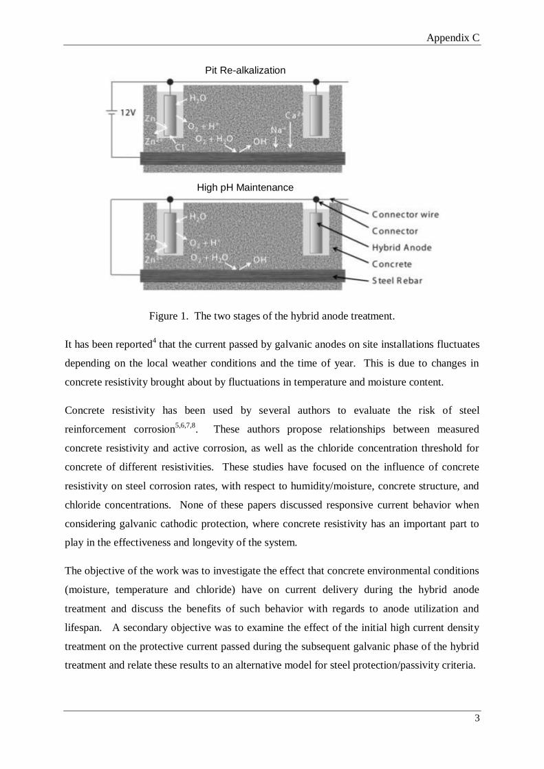
Appendix C
3
Figure 1. The two stages of the hybrid anode treatment.
It has been reported4 that the current passed by galvanic anodes on site installations fluctuates
depending on the local weather conditions and the time of year. This is due to changes in
concrete resistivity brought about by fluctuations in temperature and moisture content.
Concrete resistivity has been used by several authors to evaluate the risk of steel
reinforcement corrosion5,6,7,8
. These authors propose relationships between measured
concrete resistivity and active corrosion, as well as the chloride concentration threshold for
concrete of different resistivities. These studies have focused on the influence of concrete
resistivity on steel corrosion rates, with respect to humidity/moisture, concrete structure, and
chloride concentrations. None of these papers discussed responsive current behavior when
considering galvanic cathodic protection, where concrete resistivity has an important part to
play in the effectiveness and longevity of the system.
The objective of the work was to investigate the effect that concrete environmental conditions
(moisture, temperature and chloride) have on current delivery during the hybrid anode
treatment and discuss the benefits of such behavior with regards to anode utilization and
lifespan. A secondary objective was to examine the effect of the initial high current density
treatment on the protective current passed during the subsequent galvanic phase of the hybrid
treatment and relate these results to an alternative model for steel protection/passivity criteria.
Pit Re-alkalization
High pH Maintenance

Appendix C
4
EXPERIMENTAL
In total, 10 concrete blocks of 2 different designs were made during the study to study the
effect of the environment on the current passed by the installed anodes. The zinc/steel anode
block detailed below was designed to examine the steel and zinc anode response to
environmental factors, whereas the 9 blocks with varying chloride levels were designed to
assess the effect of different chloride levels and exposure regimes as well as the effect of an
impressed current treatment on anode current output.
A concrete block, dimensions 600 x 120 x 120 mm was cast in November 2009. A 6:1
aggregate to cement mix with a 0.32 water to cement ratio was used. Two recesses were
created on the top of the mold to house the anodes in a chloride (NaCl) contaminated mortar.
A 20 mm rebar section was cast in centrally 30 mm from the base of the mold (Figure 2).The
cylindrical anodes were cut to size in order that their surface areas were the same +/- 5%.
Both were in a non-corroded state when they were cast into the mortar. Steel connections
were made by riveting titanium wire into a drilled hole and painting over the connections with
an epoxy primer. The anode currents were logged, as with all other data, using a Campbell
Scientific CR200 data-logger.
A mortar to house the anodes was prepared with a chloride content of 5% by weight of
cement, using the same mix ratios as for the bulk concrete, but using sharp sand instead of an
aggregate mix. The block was de-molded after 2 days and left to dry in the laboratory for 90
days before being placed outdoors.

Appendix C
5
Figure 2. Zinc/steel anode block configuration.
In a separate experiment, 9 concrete samples with an 8:1 aggregate to OPC mix, at a water to
cement ratio of 0.6 were prepared in late December 2007. The samples were made with 0, 1,
2.5 or 5 % chloride by weight of cement (2 x 0 wt%, 2 x 1 wt%, 3 x 2.5 wt% and 2 x 5 wt%).
The samples were cast in wooden molds with the 15 mm diameter mild steel rebar being fed
in from the centre at one end. The approximate surface area of the steel was 230 cm2
(Figure
3). The samples were removed from the molds and left to cure in the laboratory (12-20°C,
~50-70% Relative Humidity). After a period of six months the cylindrical anode (L:14.5
W:17 mm) was installed in a drilled hole. The anode was held in place with an activating
mortar.
For 7 days a 12V power supply was used to deliver the impressed current (pit re-alkalization)
phase of the treatment before the anode was connected to the steel galvanically by a stainless
steel rivet. One of the 2.5 wt% Cl blocks did not receive the pit re-alkalization treatment and
the anode was connected to the steel galvanically throughout. Following initial treatment, the
blocks were placed outdoors. In May 2009, 4 of the 9 blocks were placed indoors (i.e., one of
each chloride level in the two regimes) with the 2.5 wt% galvanic block remaining outdoors.
A data-logger was used to record the galvanic current and the indoor and outdoor
temperatures and rainfall/meteorological events were also recorded.
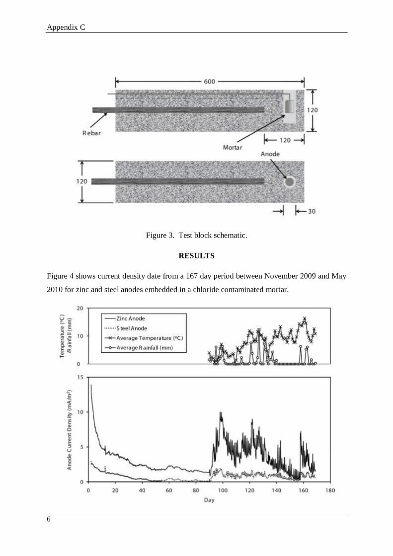
Appendix C
6
Figure 3. Test block schematic.
RESULTS
Figure 4 shows current density date from a 167 day period between November 2009 and May
2010 for zinc and steel anodes embedded in a chloride contaminated mortar.

Appendix C
7
Figure 4. Zinc and steel anode current response to environmental factors.
Figure 5 (taken from the data used in Figure 4) shows the effect of significant precipitation on
the protective current being passed by the installed anodes, with both the zinc and steel anode
current density increasing significantly after rainfall.
Figure 5. The effect of rainfall and temperature fluctuations on zinc/steel anode current.
The recorded current densities over a 29 day period for the 5 outdoor and 4 indoor blocks can
be seen in Figures 6 and 7. Figure 8 illustrates the difference in anode current density between
samples kept indoors and outdoors containing 2.5 and 0% chloride by weight of cement
respectively.

Appendix C
8
Figure 6. Current density/temperature plot for the outdoor blocks.
°
°

Appendix C
9
Figure 7. Current density/temperature plot for the indoor blocks.
°
°
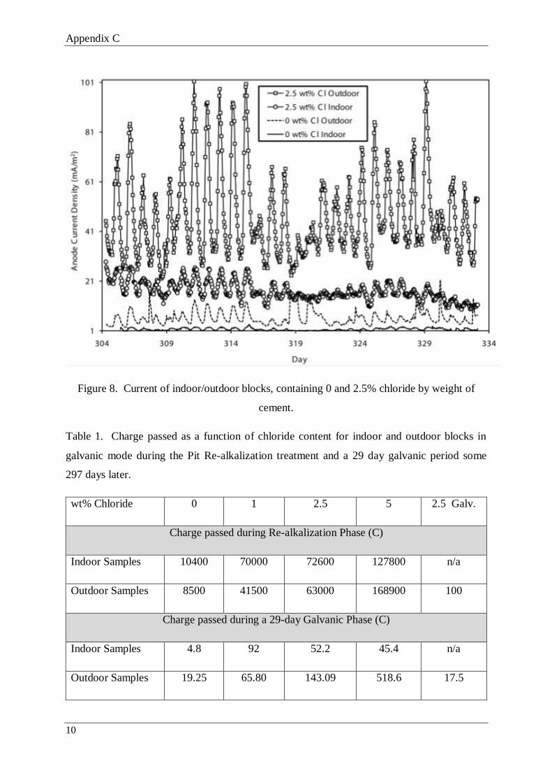
Appendix C
10
Figure 8. Current of indoor/outdoor blocks, containing 0 and 2.5% chloride by weight of
cement.
Table 1. Charge passed as a function of chloride content for indoor and outdoor blocks in
galvanic mode during the Pit Re-alkalization treatment and a 29 day galvanic period some
297 days later.
wt% Chloride 0 1 2.5 5 2.5 Galv.
Charge passed during Re-alkalization Phase (C)
Indoor Samples 10400 70000 72600 127800 n/a
Outdoor Samples 8500 41500 63000 168900 100
Charge passed during a 29-day Galvanic Phase (C)
Indoor Samples 4.8 92 52.2 45.4 n/a
Outdoor Samples 19.25 65.80 143.09 518.6 17.5

Appendix C
11
Effect of the Pit Re-alkalization Treatment on Anode Current Density
Figure 9 shows the anode current density during the pit re-alkalization phase of the hybrid
treatment and Figure 11 shows the anode current density over a 29 day period some 297 days
later. The purely galvanic block (no impressed current phase) containing 2.5% chloride by
weight of cement was used as a control sample.
After 10 months in galvanic mode, the current being passed by a hybrid anode in the sample
containing 2.5 wt% chloride is similar to that of a block containing no mixed-in chloride
which was subjected to the pit re-alkalization treatment (Figure 10). In contrast, a 2.5%
chloride block subjected to the impressed current phase is able to provide 3 to 4 times as
much protective current as a purely galvanic block in an identical environment.
Figure 9. Current passed to the steel during the pit re-alkalization phase of the hybrid
treatment
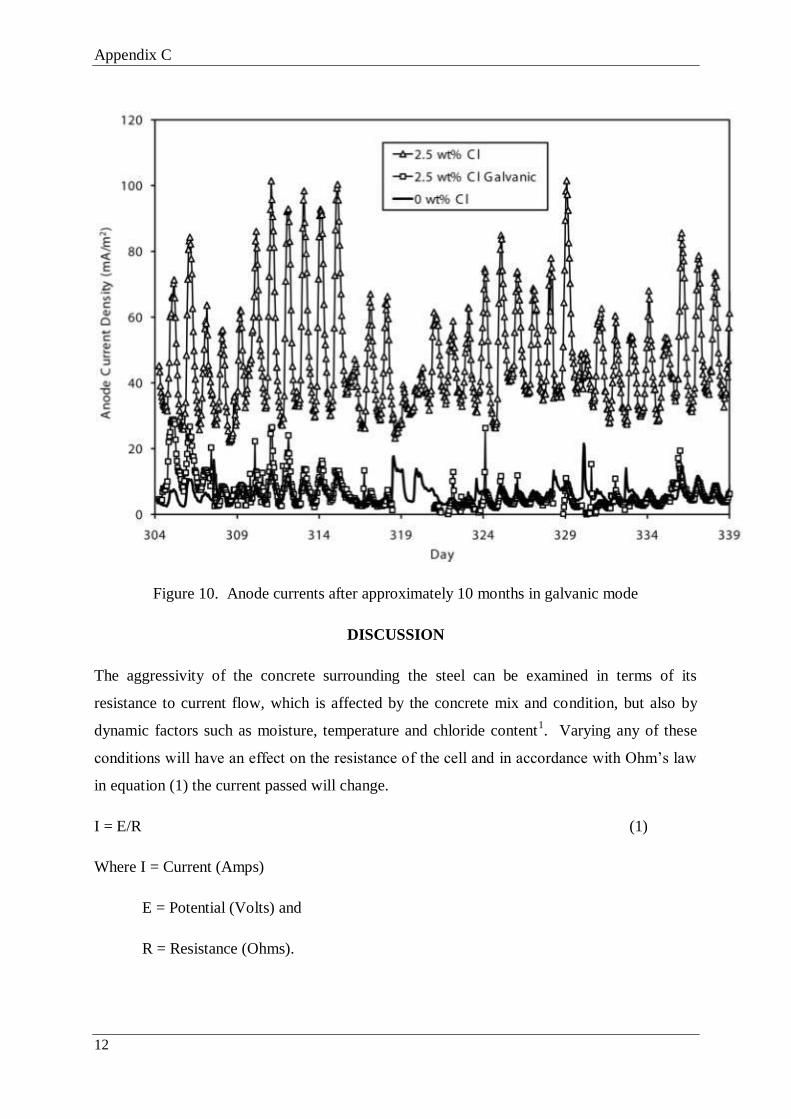
Appendix C
12
Figure 10. Anode currents after approximately 10 months in galvanic mode
DISCUSSION
The aggressivity of the concrete surrounding the steel can be examined in terms of its
resistance to current flow, which is affected by the concrete mix and condition, but also by
dynamic factors such as moisture, temperature and chloride content1. Varying any of these
conditions will have an effect on the resistance of the cell and in accordance with Ohm’s law
in equation (1) the current passed will change.
I = E/R (1)
Where I = Current (Amps)
E = Potential (Volts) and
R = Resistance (Ohms).

Appendix C
13
Taking an electronic circuit approach, each of these factors can be seen as a variable resistor
in an electrical circuit (Figure 11), with the 3 variable resistances making up the total
resistivity of the concrete. This forms a convenient method of discussing the fluctuations in
current output when concrete samples are placed in different environmental conditions.
Figure 11. The variable resistance of concrete in a galvanic cell, represented by the variable
resistances of the contributing concrete conditions.
Anode Current Responsive Behavior
Figures 4 to 8 all show the anode current density response to fluctuations in hourly/daily
temperature, with the anode current output following these fluctuations closely unless rainfall
reduces the resistivity of the concrete in the outdoor samples (Figure 5).
The effect of precipitation on concrete resistivity clearly depends on the water content of the
concrete prior to any subsequent wetting (Figure 5). After being kept in dry laboratory
conditions for ~86 days, rainfall in the first 3 days of outdoor exposure had the effect of
greatly reducing the concrete resistivity/increasing the current output of both anodes, despite
the dramatic reduction in average temperature (~15 to 4°C). Similarly, when 7 mm of rain
fell on day 119, significantly wetting the block after a week where no rain fell, the effect on
the steel current density was much greater than when ~14 mm of rain fell 6 days later. This is
likely to be because the block had retained significant moisture from the earlier rainfall.

Appendix C
14
Conversely, a spell of dry weather between days 139 and 154 caused a gradual tail-off in
anode current density due to increasing concrete resistivity and therefore reduced corrosion
risk.
Overall, Figures 4 and 5 show that the hybrid anode is capable of passing significant current
to protect the steel when the conditions demand it, but that anode life will be preserved when
the environment becomes less aggressive. It can also be said that whereas the data for the zinc
anode represents the response of galvanic protection current to environmental changes, the
current data collected from the steel anode represents fluctuations in steel corrosion rate in
response to the same changes.
It is clear from the results of the indoor and outdoor blocks in Figures 6 and 7 that the
resistivity of the concrete and therefore current delivered to the steel is heavily dependent on
the amount of chloride in the concrete mix. The 0 wt% chloride block had the lowest current
flow followed by the blocks with 1, 2.5 and 5 wt% chloride that had received the pit re-
alkalization treatment. It is also clear that the amount of chloride in the concrete determined
the degree to which the current was affected by temperature fluctuations, with the Outdoor 0
wt% Cl block showing variations of up to ~20 mA/m2 and the block with 5 wt% Cl showing
variations of up to ~250 mA/m2.
What is not is not plainly evident in Figures 6 and 7 is the difference in magnitude of the
current fluctuation as a result of the outdoor conditions. Figure 8 represents two sets of two
blocks containing the same amount of chloride, one of which has been left outdoors. The
outdoor blocks delivered ~4 times more current than the equivalent indoor 0 wt% blocks and
2.5 times more current for the equivalent 2.5 wt% blocks.
The Effect of Responsive Behavior on Anode Lifespan
The effect of responsive behavior on anode life is indicated by the current/time plots seen in
Figures 4 to 8, but is best represented by examining the charge passed to the steel by anodes
that are in different environments because in hybrid/sacrificial systems the charge passed is
directly related to metal consumption and therefore anode lifespan.
The current response during a 12V Pit Re-alkalization treatment can be seen in Figure 10.
The charge passed during the treatment increases with the aggressivity of the environment
and, as a result, so does the amount of anode material consumed.

Appendix C
15
The charge passed by the anodes during a 29 day period some 297 days later can be seen in
Table 1. The outdoor blocks demonstrate a clear relationship between chloride content and
charge passed, although the indoor blocks gave anomalous results, possibly due to the lack of
significant moisture overriding the influence of chloride in the concrete. It can also be seen
that the wetter the concrete (in the outdoor blocks) the greater the charge passed by the zinc
anode whilst the steel anode corrodes at a greater rate. The data clearly shows that by only
delivering the current when it is needed, the anode is more efficiently utilized.
The Effect of the Pit Re-alkalization Treatment on Anode Current Output
Figures 9 and 10 clearly show the effect of the impressed current (pit re-alkalization)
treatment on the current output of the hybrid anode and its response to changes in
environmental conditions. A purely galvanic block (no re-alkalization phase) containing 2.5
wt% chloride by weight of cement had a similar current output to that of a block with no
mixed-in chloride which had undergone the re-alkalization treatment (Figure 10). Removing
the pit re-alkalization treatment also has a huge influence on the charge that an anode is able
to pass. A 2.5 wt% chloride block which had not received the pit re-alkalization treatment
passed 17.6 C during a 29 day period whereas a block that had received the treatment passed
143.1 C during the same period some 11 months after the initial treatment.
The increase in anode current density and therefore charge passed is due to the effect that the
re-alkalization treatment has on both the surface of the embedded anode and the steel that it
protects. During such a high current density treatment, there is a greatly increased transfer of
ionic species through the pore structure of the concrete. Free chloride ions are drawn to the
embedded anode and hydroxide ions are drawn to the steel surface. The Cl- ions have the
effect of aiding the oxidation reaction at the anode surface, whereas the OH- ions generated at
the surface of the steel create an alkaline environment which re-passivates corroding areas by
neutralizing the acid required for continued corrosion4. The combined effect of the reactions
at the steel and anode surfaces is that the steel potential moves towards passive values
whereas the anode potential moves to more negative values. This ‘separation’ of potentials
(the driving voltage) will fluctuate with the changing resistivity of the concrete during the
galvanic phase, becoming greater when the corrosion risk is high (i.e., when it is needed) and
smaller when the corrosion risk is low. High driving voltages are difficult to achieve with a
purely galvanic anode, as modification of the steel/anode surfaces is minor at such low
current densities.

Appendix C
16
Modelling the Protective Effects of Responsive Behavior
A comparison of the two theories regarding the criteria for steel protection/passivity when
being treated by a cathodic protection system has previously been published3. In the
European standard BS EN 126969, a Pitting Potential - Repassivation model is described
(Figure 12). The model states that protection of the reinforcement is achieved by negatively
polarizing the steel to a point below the repassivation potential for a given chloride content
and holding it there to reduce corrosion to negligible levels.
Figure 12. Regions of corrosion suggested by the Pitting Potential – Repassivation model and
corresponding pitting behavior for a given chloride content9.
An alternative theory has been put forward by Glass et al3, which suggests that halting
corrosion sites by increasing the pH (by hydroxide generation) at the steel/concrete interface
is an important pre-requisite to attaining steel passivity using cathodic protection current
densities. He suggests that a temporary high current density treatment can be used to
increase the pH at the edges of anodic sites, thus gradually shrinking the area of dissolution
until the passive film is restored. This is termed the Acidification – Pit Re-alkalization model.
The proposed protection methods are distinguished from one another in Figure 13, which is a
thermodynamic model based on the Pourbaix diagram for iron and its oxides in water. The
Pitting Potential - Re-passivation model suggests that protection is achieved by lowering the
steel potential and no emphasis is put on modifying the steel surface. The Acidification – Pit
Re-alkalization model however suggests that increasing the pH/changing the environment at
the steel to halt corrosion is the main aim of the treatment.

Appendix C
17
Figure 13. Thermodynamic model for corrosion initiation and arrest (iron and its oxides in
water)10
.
On balance, the responsive behavior argument appears to fit better with the Acidification - Pit
Re-alkalization model than the Pitting potential – Repassivation model, because the former
allows the installed anodes to pass an intermittent high current when demanded (by a high
corrosion risk/low concrete resistivity), but pass very little current when the corrosion risk is
low, whilst still adequately protecting the steel. This is true for both treatment phases, for
example, when the pit re-alkalization phase is applied in aggressive conditions a high charge
will be passed and more of the sacrificial anode consumed, but more hydroxide will be
produced at the steel surface (to re-alkalize corroding sites) and more chloride drawn to the
anode (making the environment at the steel less aggressive and activating the anode).
Following the re-alkalization treatment, chemical changes at the anode/steel surface mean that
a greatly increased protective current can be driven during the galvanic phase, providing
protection to the steel under a variety of concrete conditions. In contrast, to achieve

Appendix C
18
passivation using the Pitting Potential – Repassivation model a constant current is required to
suppress the steel corrosion reaction.
CONCLUSIONS
1. The responsive behavior of sacrificial anodes allows their protective effect to be used
more efficiently. Anode life is extended in more benign environments and shortened
in more aggressive environments.
2. A brief high current can be driven off a sacrificial anode in aggressive conditions. The
current and therefore charge that is driven off the anode to arrest corrosion also
responds to the aggressive nature of the environment when a constant voltage power
supply is used to deliver the current.
3. The impressed current in the pit re-alkalization phase activates the sacrificial anode by
drawing chloride in the concrete to the anode. This can be seen by the greatly
increased current in anodes which have received the re-alkalization treatment
compared to those that have not.
4. The current output from galvanic anodes responds positively to changes in the
aggressive nature of the environment, conserving charge when the environment is
benign but able to pass high current in aggressive conditions. The model that on
balance provides the best explanation for the utilization of this responsive current
output is the pit re-alkalization/pH maintenance model where the main protective
effect is the generation of inhibitive hydroxide ions on the steel.
REFERENCES
1. J.P. Broomfield, Corrosion of steel in concrete - Understanding, investigation and
repair., (London, UK: E and FN SPON 1997).
2. G.K. Glass, N. Davison, A.C. Roberts, Hybrid Electrochemical Treatment in the
Repair of Corrosion Damaged Concrete., (Concrete Platform 2007, Queens
University, Belfast, April 2007).
3. G.K. Glass, A.C. Roberts, N. Davison, Hybrid corrosion protection for chloride
contaminated concrete, Construction Materials 161, 2008, 163-172.
4. S.P. Holmes., Repair of Corrosion Damaged Concrete Using a Two-Stage
Electrochemical Treatment, (Structural Faults and Repair 2008, Edinburgh).

Appendix C
19
5. W. Morris, A. Vico, M. Vazquez, S.R de Sanchez, Chloride induced corrosion of
reinforcing steel evaluated by concrete resistivity measurements, Electrochimica Acta,
49, 2004, 4447-4453.
6. W. Morris, A. Vico, M. Vazquez, Corrosion of reinforcing steel evaluated by means
of concrete resistivity measurements, Corrosion Science 44, 2002, 81-99.
7. F. Hunkeler, The resistivity of pore water solution – a decisive parameter of rebar
corrosion and repair methods, Construction and Building Materials, 10, No. 5, 1996,
381-389.
8. J.A. Gonzalez, W. Lopez, P. Rodrigues., Effects of Moisture Availability on
Corrosion Kinetics of Steel Embedded in Concrete, Corrosion, 49, No. 12, 1004-1010.
9. British Standard BS EN 12696 2000, Cathodic Protection of Steel in Concrete.
10. M. Pourbaix., Thermodynamics and Corrosion, Corrosion Science, 30, 1990, 963-988.


Appendix D
1
APPENDIX D - The Response of Protective Current to
Environmental Conditions During Sacrificial Anode Concrete Repair
Treatments
Full reference: Holmes, S. P. Roberts, A. Glass, G. Robins, P. Wilcox, G. (2011) Response of
protective current to environmental conditions during sacrificial anode concrete repair
treatments, Corrosion, 67(10), pp. 105005-105005-8.
Steven Holmes
Centre for Innovative and Collaborative
Engineering
Department of Civil and Building
Engineering
Loughborough University
Leicestershire, LE11 3TU, UK,
Gareth Glass
Concrete Preservation Technologies
Enterpriselab
The Sir Colin Campbell Building
University of Nottingham Innovation Park
Triumph Road, Nottingham, NG7 2TU,
Adrian Roberts
Concrete Preservation Technologies
Enterpriselab
The Sir Colin Campbell Building
University of Nottingham Innovation Park
Triumph Road, Nottingham, NG7 2TU,
Peter Robins
Department of Civil and Building
Engineering Loughborough University
Leicestershire, LE11 3TU, UK,
Geoffrey Wilcox
Department of Materials
Loughborough University
Leicestershire, LE11 3TU, UK,
ABSTRACT

Appendix D
2
This work examines the current response of installed ‘hybrid’ (combined impressed current
and sacrificial) anodes to changes in environmental conditions and investigates the effect of
this ‘responsive behavior’ on anode lifespan. The behavior reported is also discussed in
terms of its correlation with the two reported models regarding the criteria for steel protection
in concrete. The study showed that current passed by the installed anode was responsive to
changes in concrete temperature, moisture and chloride content during both the impressed
current and galvanic phases of the hybrid treatment. This meant that anode life was
conserved in benign conditions and shortened when the concrete environment was
aggressive. It was also seen that a high current density impressed current treatment
‘activated’ the installed anode, allowing it to pass a much higher current during the galvanic
phase of the treatment. The data collected fits better with the Acidification/Pit Re-alkalization
model for corrosion monitoring of steel in atmospheric concrete, rather than the Pitting
Potential/Repassivation Potential model used frequently in the industry.
Key words: Hybrid anode, sacrificial anode, re-alkalization, re-passivation, responsive
behavior, galvanic, pitting, impressed current, hydroxide.
INTRODUCTION
Over the last fifteen years there has been a dramatic increase in the use of sacrificial
galvanic anodes in the repair of corrosion damaged steel in concrete. Galvanic anodes are
used in topical applications following patch repairs, where they are attached to the steel and
immersed in the repair mortar or concrete. The aim of these anodes is to counteract the
‘incipient anode’ or ‘ring anode’ effect which can cause reinforcement corrosion due to
residual chloride in adjacent unrepaired concrete1.
In recent years, a hybrid anode system2,3 has been introduced (Figure 1). During treatment a
sacrificial anode is used as both an impressed current and galvanic anode. Initially, a
constant voltage power supply is used to drive a high current from the installed anode to re-
passivate the steel and draw chloride to the anode (Pit Re-alkalization phase). The same
anode is then connected directly to the steel to provide maintenance free cathodic protection
by means of a galvanic current (High pH Maintenance phase). Instead of being installed in
the patch repair, the anodes are placed in adjacent un-repaired concrete to counteract the
anodic behavior of the steel.

Appendix D
3
Figure 1. The two stages of the hybrid anode treatment; a) Impressed current/Pit re-
alkalisation b) High pH maintenance.
It has been reported4 that the current passed by galvanic anodes on site installations
fluctuates depending on the local weather conditions and the time of year. This is due to
changes in concrete resistivity brought about by fluctuations in temperature and moisture
content.
Concrete resistivity has been used by several authors to evaluate the risk of steel
reinforcement corrosion5,6,7,8. These authors propose relationships between measured
concrete resistivity and active corrosion, as well as the chloride concentration threshold for
concrete of different resistivities. These studies have focused on the influence of concrete
resistivity on steel corrosion rates, with respect to humidity/moisture, concrete structure, and
chloride concentrations. None of these papers discussed current response to resistance
changes in the concrete when considering galvanic cathodic protection, where concrete
resistivity has an important part to play in the effectiveness and longevity of the system.
The objective of the work was to investigate the effect that concrete environmental conditions
(moisture, temperature and chloride) have on current delivery during the hybrid anode
treatment and discuss the benefits of such behavior with regards to anode utilization and
lifespan. A secondary objective was to examine the effect of the initial high current density
treatment on the protective current passed during the subsequent galvanic phase of the
hybrid treatment and relate these results to an alternative hypothesis regarding steel
protection criteria.
EXPERIMENTAL

Appendix D
4
A concrete block, dimensions 600 x 120 x 120 mm was cast in November 2009. A 6:1
aggregate to cement mix with a 0.32 water to cement ratio was used. Two recesses were
created on the top of the mold to house the anodes in a chloride (NaCl) contaminated mortar
which was prepared with a chloride content of 5% by weight of cement, using the same mix
ratios as for the bulk concrete, but using sharp sand instead of an aggregate mix. A 20 mm
rebar section was cast in centrally 30 mm from the base of the mold (Figure 2).The
cylindrical anodes were cut to size (65 x 15 mm) in order that their surface areas were the
same +/- 5%. Both were in a non-corroded state when they were cast into the mortar. Steel
connections were made by riveting titanium wire into a drilled hole and painting over the
connections with an epoxy primer. The anode currents were recorded using a data-logger.
Figure 2. Embedded zinc/steel anode block; a) side elevation, b) plan elevation.
The block was de-moulded after 2 days and left to dry in the laboratory for 90 days before
being placed outdoors. Temperature and rainfall data was obtained retrospectively from a
public domain source.
In a separate experiment, 9 concrete samples with an 8:1 aggregate to OPC mix, at a water
to cement ratio of 0.6 were prepared. The samples were made with 0, 1, 2.5 or 5 % chloride
by weight of cement (2 x 0 wt%, 2 x 1 wt%, 3 x 2.5 wt% and 2 x 5 wt%) and cast in wooden
molds with a 15 mm diameter mild steel rebar being fed in from the centre at one end. The
approximate surface area of the steel was 230 cm2 (Figure 3). The samples were removed
from the molds and left to cure in the laboratory (12-20°C, ~50-70% Relative Humidity). After
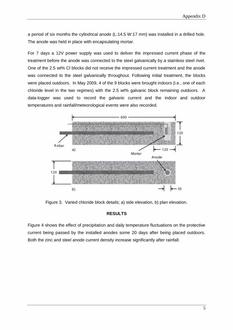
Appendix D
5
a period of six months the cylindrical anode (L:14.5 W:17 mm) was installed in a drilled hole.
The anode was held in place with encapsulating mortar.
For 7 days a 12V power supply was used to deliver the impressed current phase of the
treatment before the anode was connected to the steel galvanically by a stainless steel rivet.
One of the 2.5 wt% Cl blocks did not receive the impressed current treatment and the anode
was connected to the steel galvanically throughout. Following initial treatment, the blocks
were placed outdoors. In May 2009, 4 of the 9 blocks were brought indoors (i.e., one of each
chloride level in the two regimes) with the 2.5 wt% galvanic block remaining outdoors. A
data-logger was used to record the galvanic current and the indoor and outdoor
temperatures and rainfall/meteorological events were also recorded.
Figure 3. Varied chloride block details; a) side elevation, b) plan elevation.
RESULTS
Figure 4 shows the effect of precipitation and daily temperature fluctuations on the protective
current being passed by the installed anodes some 20 days after being placed outdoors.
Both the zinc and steel anode current density increase significantly after rainfall.

Appendix D
6
Figure 4. The effect of rainfall and temperature fluctuations on zinc and steel anode currents
over a 13 day period.
The recorded current densities over a 29 day period for the 5 outdoor and 4 indoor blocks
can be seen in Figures 5 and 6. Figure 7 illustrates the difference in anode current density
between samples kept indoors and outdoors containing 2.5 and 0% chloride by weight of
cement, respectively.
Table 1.Charge Passed as a Function of Chloride Content for Indoor and Outdoor Blocks in
Galvanic Mode During the Pit Re-alkalization Treatment and a 29 Day Galvanic Period some
297 Days Later.
wt% Chloride 0 1 2.5 5 2.5 Galv.
Charge passed during Re-alkalization Phase (C)
Indoor Samples 10400 70000 72600 127800 n/a
Outdoor Samples 8500 41500 63000 168900 100
Charge passed during a 29-day Galvanic Phase (C)
Indoor Samples 4.8 92 52.2 45.4 n/a
Outdoor Samples 19.25 65.80 143.09 518.6 17.5

Appendix D
7
Figure 5. Current density/temperature plot for the outdoor blocks between day 304 and day
339.
Figure 6. Current density/temperature plot for the indoor blocks between day 304 and 339.

Appendix D
8
Figure 7. Current of indoor/outdoor blocks, containing 0 and 2.5% chloride by weight of
cement.
Figure 8. Current passed to the steel during the pit re-alkalization phase of the hybrid
treatment

Appendix D
9
Figure 9. Anode current density after approximately 10 months in galvanic mode.
Effect of the Impressed Current Treatment on Anode Current Density
Figure 8 shows the anode current density during the impressed current phase of the hybrid
treatment and Figure 9 shows the anode current density over a 29 day period some 297
days later. The purely galvanic block (no impressed current phase) containing 2.5% chloride
by weight of cement was used as a control sample.
After 10 months in galvanic mode, the current being passed by a hybrid anode in the sample
containing 2.5 wt% chloride is similar to that of a block containing no mixed-in chloride which
was subjected to the impressed current treatment (Figure 9). In contrast, a 2.5% chloride
block subjected to the impressed current phase is able to provide 3 to 4 times as much
protective current as a purely galvanic block in an identical environment.
DISCUSSION
The Effect of the Pit Re-alkalization Treatment on Anode Current Output
Figures 8 and 9 clearly show the effect of the impressed current (pit re-alkalization) treatment
on the current output of the hybrid anode and its response to changes in environmental
conditions. A purely galvanic block (no re-alkalization phase) containing 2.5 wt% chloride by
weight of cement had a similar current output to that of a block with no mixed-in chloride

Appendix D
10
which had undergone the re-alkalization treatment (Figure 9). Removing the pit re-
alkalization treatment also has a huge influence on the charge that an anode is able to pass.
A 2.5 wt% chloride block which had not received the pit re-alkalization treatment passed 17.6
C during a 29 day period whereas a block that had received the treatment passed 143.1 C
during the same period some 11 months after the initial treatment.
The increase in anode current density and therefore charge passed is due to the effect that
the re-alkalization treatment has on both the surface of the embedded anode and the steel
that it protects. During such a high current density treatment, there is a greatly increased
transfer of ionic species through the pore structure of the concrete. Un-bound chloride ions
are drawn to the embedded anode and hydroxide ions are drawn to the steel surface. The
Cl- ions have the effect of aiding the oxidation reaction at the anode surface, whereas the
OH- ions generated at the surface of the steel create an alkaline environment which re-
passivates corroding areas by neutralizing the acid required for continued corrosion4. The
combined effect of the reactions at the steel and anode surfaces is that the steel potential
moves towards passive values whereas the anode potential moves to more negative values.
This ‘separation’ of potentials (the driving voltage) will fluctuate with the changing resistivity
of the concrete during the galvanic phase, becoming greater when the corrosion risk is high
(i.e., when it is needed) and smaller when the corrosion risk is low. High driving voltages are
difficult to achieve with a purely galvanic anode, as modification of the steel/anode surfaces
is minor at such low current densities.
Anode Current Responsive Behavior
The aggressivity of the concrete surrounding the steel and the anode concrete interface can
be examined in terms of its resistance to current flow, which is affected by the concrete mix
and condition, but also by dynamic factors such as moisture, temperature and chloride
content1. Varying any of these conditions will have an effect on the resistance of the cell and
in accordance with Ohm’s law the current passed will change.
Taking an electronic circuit approach, each of these factors can be seen as a variable
resistor in an electrical circuit (Figure 10), with the 3 variable resistances making up the total
resistivity of the concrete. This forms a convenient method of discussing the fluctuations in
current output when concrete samples are placed in different environmental conditions.

Appendix D
11
Figure 10. The variable resistance of concrete in a galvanic cell, represented by the variable
resistances of the contributing concrete conditions.
Figures 4 to 7 all show the anode current density response to fluctuations in hourly/daily
temperature, with the anode current output following these fluctuations closely unless rainfall
reduces the resistivity of the concrete in the outdoor samples.
The effect of precipitation on concrete resistivity clearly depends on the water content of the
concrete prior to any subsequent wetting (Figure 4). When rain fell on day 119, wetting the
block after a week where no rain fell, the effect on the steel current density was considerably
greater than when a larger amount of rain fell on day 124. This is likely to be because the
block had retained significant moisture from the earlier rainfall.
Overall, Figure 4 shows that the hybrid anode is capable of passing significant current to
protect the steel when the conditions demand it, but that anode life will be preserved when
the environment becomes less aggressive.
It is clear from the results of the indoor and outdoor blocks in Figures 5 and 6 that the
resistivity of the concrete and therefore current delivered to the steel is dependent on the
amount of chloride in the concrete mix. In the outdoor blocks the 0 wt% chloride sample had
the lowest current flow, followed by the blocks with 1, 2.5 and 5 wt% chloride that had
received the pit re-alkalization treatment. The indoor blocks gave anomalous results with the
2.5 and 5 wt% blocks having similar current densities. It is probable that this is due to the
lack of significant moisture overriding the influence of chloride in the concrete in such a dry
environment. It is also clear that the amount of chloride in the concrete determined the

Appendix D
12
degree to which the current was affected by temperature fluctuations, with the Outdoor 0
wt% Cl block showing variations of up to ~20 mA/m2 and the block with 5 wt% Cl showing
variations of up to ~250 mA/m2. What is not is not plainly evident in Figures 5 and 6 is the
difference in magnitude of the current fluctuation as a result of the outdoor conditions. Figure
8 represents two sets of two blocks containing the same amount of chloride, one of which
has been left outdoors. The outdoor blocks delivered ~4 times more current than the
equivalent indoor 0 wt% blocks and 2.5 times more current for the equivalent 2.5 wt% blocks.
The Effect of Responsive Behavior on Anode Lifespan
The effect of responsive behavior on anode life is indicated by the current/time plots seen in
Figures 4 to 7, but is best represented by examining the charge passed to the steel by
anodes that are in different environments because in hybrid/sacrificial systems the charge
passed is directly related to metal consumption and therefore anode lifespan.
The current response during a 12V Pit Re-alkalization treatment can be seen in Figure 9.
The charge passed during the treatment increases with the aggressivity of the environment
and, as a result, so does the amount of anode material consumed.
The charge passed by the anodes during a 29 day period some 297 days later can be seen
in Table 1. The outdoor blocks (Figure 5) demonstrate a clear relationship between chloride
content and charge passed and it can be seen that the wetter the concrete (in the outdoor
blocks) the greater the charge passed by the zinc anode whilst the steel anode corrodes at a
greater rate. The data clearly shows that by only delivering the current when it is needed,
the anode is more efficiently utilized.
Modeling the Protective Effects of Responsive Behavior
A comparison of the two hypotheses regarding the criteria for steel protection/passivity when
being treated by a cathodic protection system has previously been published3. In the current
European standard (Figure 11)9, a Pitting Potential/Repassivation Potential hypothesis is
described which states that protection of the reinforcement is achieved by negatively
polarizing the steel to a point below the repassivation potential for a given chloride content.

Appendix D
13
Figure 11. Regions of corrosion suggested by the Pitting Potential – Repassivation model
and corresponding pitting behavior for a given chloride content9.
An alternative theory has been put forward by Glass et al3, which suggests that halting
corrosion sites by increasing the pH (by hydroxide generation) at the steel/concrete interface
is an important pre-requisite to attaining steel passivity using cathodic protection current
densities. He suggests that a temporary high current density treatment can be used to
increase the pH at the edges of anodic sites, thus gradually shrinking the area of dissolution
until the passive film is restored. This is termed the Acidification/Pit Re-alkalization
hypothesis.
The Pitting Potential/Re-passivation Potential hypothesis suggests that protection is
achieved by lowering the steel potential (zone D to zone B in Figure 11) and no emphasis is
put on modifying the steel surface. The Acidification/Pit Re-alkalization model however
suggests that increasing the pH/changing the environment at the steel to halt corrosion is the
main aim of the treatment (point a to point c in Figure 12) with a positive steel potential shift
often being measured as a secondary effect3,4,10,11.
Figure 12. The approach for achieving steel protection with the Acidification/Pit Re-
alkalization hypothesis, based on the Pourbaix diagram for iron and its oxides in water12.

Appendix D
14
On balance, the responsive behavior argument appears to fit better with the Acidification/Pit
Re-alkalization hypothesis than the Pitting potential/Repassivation Potential hypothesis,
because the former allows the installed anodes to pass an intermittent high current when
demanded (by a high corrosion risk/low concrete resistivity), but pass very little current when
the corrosion risk is low, whilst still adequately protecting the steel. This is true for both
treatment phases, for example, when the impressed current phase is applied in aggressive
conditions a high charge will be passed and more of the sacrificial anode consumed, but
more hydroxide will be produced at the steel surface (to re-alkalize corroding sites) and more
chloride drawn to the anode (making the environment at the steel less aggressive and
activating the anode). Following the re-alkalization treatment, chemical changes at the
anode/steel surface mean that a greatly increased protective current can be driven during the
galvanic phase, providing protection to the steel under a variety of concrete conditions. In
contrast, to achieve protection with the Pitting Potential/Re-passivation Potential hypothesis,
permanent polarization is required and current fluctuations are something that must be
controlled during the treatment.
CONCLUSIONS
1. A brief high current can be driven off a sacrificial anode in aggressive conditions. The
current and therefore charge that is driven off the anode to arrest corrosion also
responds to the aggressive nature of the environment when a constant voltage power
supply is used to deliver the current.
2. A brief impressed current treatment activates the sacrificial anode by drawing chloride
in the concrete to the anode. This can be seen by the greatly increased current in
anodes which have received the impressed current treatment compared to those that
have not.
3. The responsive behavior of sacrificial anodes means that their protective capacity is
used more efficiently. Anode life is extended in more benign environments and
shortened in more aggressive environments.
4. The Pit Re-alkalization/pH Maintenance hypothesis provides a basis for using a brief
impressed current phase in conjunction with a galvanic phase where the main
protective effect is the generation of inhibitive hydroxide ions on the steel.
5.

Appendix D
15
REFERENCES
1. J.P. Broomfield, Corrosion of steel in concrete - Understanding, investigation and
repair., (London, UK: E and FN SPON 1997).
2. G.K. Glass, N. Davison, A.C. Roberts, Hybrid Electrochemical Treatment in the Repair
of Corrosion Damaged Concrete., (Concrete Platform 2007, Queens University, Belfast,
April 2007).
3. G.K. Glass, A.C. Roberts, N. Davison, Hybrid corrosion protection for chloride
contaminated concrete, Construction Materials 161, 2008, 163-172.
4. S.P. Holmes., Repair of Corrosion Damaged Concrete Using a Two-Stage
Electrochemical Treatment, (Structural Faults and Repair 2008, Edinburgh).
5. W. Morris, A. Vico, M. Vazquez, S.R de Sanchez, Chloride induced corrosion of
reinforcing steel evaluated by concrete resistivity measurements, Electrochimica Acta
49, 2004, 4447-4453.
6. W. Morris, A. Vico, M. Vazquez, Corrosion of reinforcing steel evaluated by means of
concrete resistivity measurements, Corrosion Science 44, 2002, 81-99.
7. F. Hunkeler, The resistivity of pore water solution – a decisive parameter of rebar
corrosion and repair methods, Construction and Building Materials 10, 5, 1996, 381-389.
8. J.A. Gonzalez, W. Lopez, P. Rodrigues., Effects of Moisture Availability on Corrosion
Kinetics of Steel Embedded in Concrete, Corrosion 49, 12, 1004-1010.
9. British Standard BS EN 12696 2000, Cathodic Protection of Steel in Concrete, British
Standards Institution, 1999.
10. G.K. Glass, J.R Chadwick, An investigation into the mechanisms of protection afforded
by a cathodic current and the implications for advances in the field of cathodic
protection, Corrosion Science 36, 12, 1994, 2193-2209.

Appendix D
16
11. G.K Glass, A.M. Hassanein, N.R. Buenfeld, Cathodic protection afforded by an
intermittent current applied to reinforced concrete, Corrosion Science 43, 6, 2001, 1111-
1131.
12. M. Pourbaix., Thermodynamics and Corrosion, Corrosion Science, 30, 1990, 963-98.
Appendix E
1
APPENDIX E - The Responsive Behaviour of Galvanic Anode
Current in Concrete and the Basis for its Utilisation
Full reference: Holmes, S. P. Wilcox, G.D. Robins, P. J. Glass, G. K. Roberts, A. C. (2011)
Responsive behaviour of galvanic anodes in concrete and the basis for its utilisation,
Corrosion Science, 53, pp.3450-3454.
*S.P. Holmesa, G.D. Wilcox
a, P.J. Robins
a, G.K. Glass
b, A.C. Roberts
b
aDepartment of Materials/CICE, Civil and Building Engineering, Loughborough University,
Leicestershire, LE11 3TU. [email protected], Tel: +44(0)7816525419, Fax:
+44(0)1509223982
bConcrete Preservation Technologies, The Sir Colin Campbell Building, University of
Nottingham Innovation Park, Triumph Road, Nottingham, NG7 2TU
*Corresponding author
ABSTRACT
In this study, a unique concrete specimen was used to analyse the response of embedded
sacrificial zinc and steel anodes to rainfall and fluctuations in temperature. Current from the
zinc and steel anodes increased when the environment was aggressive, showing that the
required protection current depends on the present level of corrosion risk. A basis for
using the ‘responsive behaviour’ of galvanic anodes is provided by the protective effects of
pit re-alkalisation and pH maintenance. By contrast, protection based on achieving adequate
polarisation inhibits the use of responsive behaviour and galvanic anodes might only deliver
adequate polarisation in aggressive environments.
Keywords
A. Steel reinforced concrete
A. Steel
A. Zinc
B. Polarisation
C. Cathodic Protection

Appendix E
2
C. Passivity
INTRODUCTION
Electrochemical treatments are widely used in the mitigation of steel reinforcement corrosion.
There is much debate within academia and industry regarding which treatment approach
tackles the dominant factor affecting steel corrosion in concrete. It has been argued that
adequately cathodically polarising the steel is the dominant protective effect. This is
supported by the Pitting Potential/Re-passivation Potential hypothesis [1]. By contrast, it has
been suggested that modifying the surface of the steel by raising the pH is the dominant
protective effect, with reports that typical Impressed Current Cathodic Protection current
densities are enough to halt corrosion when applied for long periods [2,3], or delay its onset in
aggressive environments once the protective current has been removed [4,5]. These
observations support the basis of the Pit Re-alkalisation/pH Maintenance hypothesis [6-8].
It has been reported that the current passed by galvanic anodes on site and in laboratory
installations fluctuates depending on the local weather conditions and the time of year. The
phenomena has been termed ‘Responsive Behaviour’ [9,10]. This brief study used a unique
experimental design to investigate the effect of fluctuations in temperature and concrete
moisture content on the current output of separate zinc and steel anodes encased in the same
concrete sample. These results are then discussed with respect to the practical benefits of
responsive behaviour and the protection criteria applied to steel in concrete.
SAMPLE PREPARATION
A concrete block, dimensions 600 x 120 x 120 mm was cast in November 2009. A 6:1
aggregate to cement mix with a 0.32 water to cement ratio was used. Two recesses were
created on the top of the mould to house the anodes in a chloride (NaCl) contaminated mortar
which was prepared with a chloride content of 5% by weight of cement, using the same mix
ratios as for the bulk concrete, but using sharp sand instead of an aggregate mix. A 20 mm
rebar section was cast in centrally 30 mm from the base of the mould (Figure 1).The
cylindrical anodes were cut to size (65 x 15 mm) in order that their surface areas were the
same +/- 5%. Both were in a non-corroded state when they were cast into the mortar. Steel
connections were made by riveting titanium wire into a drilled hole and painting over the
connections with an epoxy primer. The anode currents were logged using a data-logger.

Appendix E
3
Figure 1. Embedded zinc and steel anode block; a) side elevation, b) plan elevation (All
dimensions in mm).
The block was de-moulded after 2 days and left to dry in the laboratory for 90 days before
being placed outdoors. Temperature and rainfall data was obtained retrospectively from a
public domain source.
EXPERIMENTAL FINDINGS
Figure 2 shows the current densities of the zinc and steel anodes, along with temperature and
rainfall data. Both anodes were embedded in a chloride contaminated mortar but as the steel
bar was installed in chloride-free mortar with significant cover it was not expected to be
corroding. This test arrangement resulted in metal dissolution at the installed zinc and steel
anodes providing a cathodic current to the steel bar. The large increase in the anode current
densities on day 67 was as a result of rainfall after a period of dry weather.

Appendix E
4
Figure 2. Steel anode current response to rainfall and changes in temperature.
The general decay in both zinc and anode current density is likely to be the result of a build
up of corrosion products at the anode surface and a resulting increase in the resistance to
current flow from the anodes.
Figure 3 is hourly data taken from the data used in Figure 2 and shows the anode response to
rainfall in more detail. It can be seen that the zinc anode responded more quickly to the rapid
environmental change. In contrast, Figure 4 shows the anode current densities on a day when
no rain fell. It can be seen that in the absence of any ‘shock’ changes to the environment, the
current outputs from both anodes follows the changes in daily temperature.
The ratio of the zinc and steel current densities (Figures 3 and 4) is a good indicator of the
amount of protection offered to the steel by the zinc anode; when it is large, the zinc is

Appendix E
5
offering more protective current than when the ratio is small. It can be seen that the protection
offered to the steel increases when the environment becomes more aggressive.
Figure 3. The zinc and steel anode current density response to sudden rainfall and the
resulting effect on the protective ratio.

Appendix E
6
Figure 4. The zinc and steel anode current density response to dry weather and the resulting
effect on the protective ratio.
DISCUSSION
In this work the zinc anode represents a galvanic anode installed in contaminated concrete and
the steel anode represents a section of corroding steel rebar. The current density recorded for
the steel anode gives an indication of the amount of corrosion activity occurring on the steel
bar and represents the steel corrosion risk, whilst the zinc anode galvanic current represents
the protective current. In this work both the zinc and steel response to environmental
conditions have been recorded.
Responsive Behaviour
The steel current density gives a good indication of the need for protective current. It can be
seen in Figure 2 that as the concrete dries (between days 50 and 67), the steel and zinc anode
current densities fall and the difference between them becomes smaller. The steel requires
little protective current as the corrosion risk is low due to the resistance of the drying
concrete. In this state, little current is required to adequately protect the steel from corrosion.

Appendix E
7
On day 67 rainfall greatly reduced the resistance of the concrete, causing a significant
increase in the steel corrosion current and an order of magnitude increase in the protective
current. In this state the steel requires more protective current in order to maintain passivity as
the reduction in overall concrete resistivity reduces the restriction on ionic flow and increases
the corrosion risk. In this state, increased current is required to fully protect the steel. It can
be seen that the installed zinc anode responds to the environment-related requirement for
protective current.
Current output from the zinc anode responds to changes in the aggressive nature of the
environment, passing a high current when required to address a high steel corrosion risk
(signified by increased steel anode current) and low current when there is a low steel
corrosion risk.
Theoretical considerations
Available electrochemical treatments for corrosion mitigation ascribe to one of two
approaches. Re-alkalisation [11] and Electrochemical Chloride Extraction [12] treatments aim
to make the environment at the steel surface less aggressive by increasing the pH (by
generating hydroxide), or removing aggressive chloride ions, thus re-instating passivity. They
are termed temporary treatments because the treatment time is short compared to the period of
the protection offered. Cathodic protection (galvanic or impressed current) is a long term
treatment which aims to suppress the steel corrosion reactions by permanently polarising the
steel reinforcement [13]. A common protection criterion applied to cathodic protection
systems [1] suggests that a 100 mV steel depolarisation is required on disconnection of the
anode system.
The concept of adequate polarisation requires the potential to be depressed below the pitting
potential to prevent corrosion initiation. The pitting potential depends on factors such as
concrete chloride content, so the use of cathodic protection as a corrosion prevention
technique is associated with the pitting potential of reinforcing steel at some future chloride
content. Because of this, it has been argued that a much larger potential shift is required.
Values of up to 400 mV have been suggested [4,14,15]. The requirement for a potential shift
of less than 100 mV to signify protection has little support in the academic literature.
What is not adequately considered by this concept is that the removal of chloride and the
generation of hydroxide under polarisation will raise the pitting potential and hence reduce

Appendix E
8
the magnitude of what constitutes adequate polarisation. This makes the protective effect of
adequate polarisation a variable that is primarily determined by chloride removal and
hydroxide generation, depending on which factor is dominant.
A protective effect based on the generation of hydroxide under an applied current has been
termed Pit Re-alkalisation [16]. The effects of pit re-alkalisation, chloride extraction from pits
and polarisation have been compared by others and on balance pit re-alkalisation and pH
maintenance appear to be the dominant protective effects at typical cathodic protection
current densities [17]. Indeed brief high current treatments have been shown to raise the
chloride threshold level for corrosion initiation to values substantially greater than 2%
chloride by weight of cement [5]. It is postulated that this is due to the generation of
hydroxide at the steel.
The perceived need for polarisation inhibits the use of responsive behaviour. Current
controlled power-supplies are predominantly used in Impressed Current Cathodic Protection
systems to suppress current fluctuations in order to maintain consistent polarisation levels
[18]. Another example is the suggestion that galvanic anode systems should only be applied
in aggressive environments [19-21], because it is only in this environment that they can
deliver sufficient current to meet the 100 mV criteria.
As shown in the present work, steel in benign concrete environments does not corrode and
therefore requires no protective current. This is consistent with a system based on the
protective effects of pit re-alkalisation and pH maintenance. Steel in aggressive environments
does corrode, and protective current is required to either restore a high pH at the site of a pit
or prevent a local pH reduction and hence pit formation. The protection offered by pit re-
alkalisation and pH maintenance depends on the present level of corrosion risk rather than the
future risk. A cathodic protection system based on pit re-alkalisation and pH maintenance can
fully utilise galvanic anode responsive behaviour.
Environmental ‘Shock’
Figure 3 uses data from Figure 2 to show the zinc and steel anode current response to
significant rainfall after a period of dry weather. This preliminary data suggests that the zinc
anode responds more rapidly than the steel anode to the large increase in corrosion risk
arising from ‘environmental shock’, in this case, rainfall. Such a feature would ensure that the
protective current is greatly increased prior to any increased demand from the steel. It is

Appendix E
9
postulated that the quicker response to corrosion risk by the zinc anode is due to the nature of
the corrosion products which surround the two different materials, whose conductivity will
dictate the speed of the anode response to changes in moisture content. Another explanation is
that the polarising effect of the zinc anode slowed the response of the steel anode, thus
contributing to the apparent rapid response of the zinc anode. The disparity in the anode
response means that there is a dramatic increase in the ‘protective ratio’ (the difference
between the zinc and steel current output) and therefore the amount of protection offered by
the zinc. As the steel corrosion risk increased, the ratio stabilised at a more typical level.
In the absence of rain, the peak seen in Figure 4 is predominantly related to the temperature
rise and fall during daylight hours. The data clearly shows that when the concrete
environment is more aggressive (the temperature is higher) the zinc anode provides more
protection to the steel although due to the more gradual changes in conditions there is no
advanced response from the zinc. Even in relatively benign conditions (low temperature and
dry concrete), the zinc responds to changes in corrosion risk.
Practical Considerations
As the current passed by the anodes is directly related to their consumption and therefore
lifespan, Figure 2 demonstrates how anode life is conserved when the concrete environment is
benign (during periods of little or no rain) and how it is shortened when conditions become
more aggressive. It also shows that having an active anode surface is the key to obtaining
adequate protection as the zinc anode is able to increase its current output dramatically as
soon as the concrete environment becomes more aggressive.
The sole sample for the work (Figure 1) had a unique design and was specially made to
investigate the relationship between fluctuations in corrosion risk and galvanic anode current
output. It was not designed with the intention of using the zinc anode to protect the steel
anode from corrosion. Further tests on replicate samples are underway to corroborate the data
collected, although observations from both site and laboratory installations [9,10,22] reinforce
the results presented.
CONCLUSIONS
1. It is shown for the first time that the current output of a zinc anode corresponds to the steel
corrosion current in the same changing concrete environment. A high current is passed when
Appendix E
10
required to address a high steel corrosion risk and a low current is passed when there is a low
steel corrosion risk. This is termed responsive behaviour of the galvanic protection current.
2. A basis for using the responsive behaviour of galvanic anodes is provided by the protective
effects of pit re-alkalisation and pH maintenance. In benign environments no current is
required to achieve pit re-alkalisation or maintain the pH, whilst in aggressive environments
current is required to either restore a high pH at the site of a pit or prevent a local pH
reduction and hence pit formation. The required protection current depends on the present
level of corrosion risk. By contrast, protection based on achieving adequate polarisation
inhibits the use of responsive behaviour and galvanic anodes might only deliver adequate
polarisation in aggressive environments.
3. Preliminary data indicates that a zinc anode responds to environmental ‘shock’ events more
rapidly than a steel anode, meaning that the protective current being passed to the steel is
greatly increased just prior to increased corrosion risk. Postulated reasons include the higher
conductivity of the zinc corrosion products or the polarising effect of the zinc anode causing a
delay in the steel response to the increased corrosion risk.
4. The Pit Re-alkalisation/pH Maintenance hypothesis provides a basis for achieving
corrosion protection with less integrated current (charge) than theories based on adequate
polarisation. Responsive behaviour means that anode life is conserved in benign environments
as the charge passed is less and therefore less anode material is consumed. This supports the
conclusions of previous work.
REFERENCES
[1] British Standard BS EN 12696:2000, Cathodic Protection of Steel in Concrete, British
Standards Institution, 1999.
[2] G.K. Glass, A.C. Roberts, N. Davison, Hybrid corrosion protection for chloride
contaminated concrete, Construction Materials 161 (2008) 163-172.
[3] C. Christodoulou, G. Glass, J. Webb, S. Austin, C. Goodier, Assessing the long term
benefits of Impressed Current Cathodic Protection, Corrosion Science 52 (2010) 2671-
2679

Appendix E
11
[4] F.J. Presuel-Moreno, A.A. Sagues, S.C. Kranc, Steel activation in concrete following
interruption of long term cathodic polarisation, CORROSION 2002, Houston, Texas,
(Paper No. 02259).
[5] G.K. Glass, B. Reddy, L. Clark, Making reinforced concrete immune from chloride
corrosion, Proceedings Institution Civil Engineers, Construction Materials, 160
(2007) 155-164.
[6] G.K. Glass, N. Davison, A.C. Roberts, Hybrid Electrochemical Treatment in the
Repair of Corrosion Damaged Concrete, Concrete Platform 2007, Queens University,
Belfast, April 2007.
[7] G.K. Glass, N.R. Buenfeld, The inhibitive effects of electrochemical treatment applied
to steel in concrete, Corrosion Science 42, 6, (2000) 923-927.
[8] G.K. Glass, N. Davison, A.C. Roberts, Pit re-alkalisation and its role in the
electrochemical repair of reinforced concrete, Cathodic Protection Conference,
University of Manchester, 2006.
[9] S.P. Holmes, G.K. Glass, A.C. Roberts, P. Robins, G.D. Wilcox, the response of
protective current to environmental conditions during hybrid anode concrete repair
treatments, CORROSION 2011, Houston, Texas (Paper no. 19132).
[10] S.P. Holmes, The response of galvanic protection current to environmental changes,
EUROCORR 2009, Nice, France (Paper no. 8254).
[11] J. P. Broomfield, Electrochemical Re-alkalisation of Steel Reinforced Concrete - A
State of the Art Report, Corrosion Prevention Association Technical Note No: 9,
2005.
[12] J.C. Orellan, G. Escadeillas, G. Arliguie, Effectiveness and structural implications of
electrochemical chloride extraction from reinforced concrete beams, Cement and
Concrete Research 34 (2004) 227–234.
[13] J.P.Broomfield, Corrosion of Steel in Concrete, understanding, investigation and
repair, E and F Spon, London, 1997.

Appendix E
12
[14] J. P. Broomfield, The Principles and Practice of Galvanic Cathodic Protection for
Reinforced Concrete, Corrosion Prevention Association Technical Note No: 6, 2005.
[15] K. Takewaka, Cathodic protection for reinforced-concrete and prestressed-concrete
structures, Corrosion Science 35, 5-8, (1993) 1617-1626.
[16] G. K. Glass, N. Davison, A. C. Roberts, Pit re-alkalisation and its role in the
electrochemical repair of reinforced concrete, The Journal of Corrosion Science and
Engineering 9 (2007) Paper 10.
[17] G.K. Glass, A.C. Roberts, N. Davison, Hybrid corrosion protection for chloride
contaminated concrete, Construction Materials 161 (2008) 163-172.
[18] A. A. Sagues, M. Dugarte, Galvanic Point Anodes for Extending the Service Life of
Patched Areas Upon Reinforced Concrete Bridge Members, Florida Department of
Transportation, Report No. BD544 – 09, 2009.
[19] A. A. Sagues, R. G. Powers, Sprayed Zinc Galvanic Anodes for Concrete Marine
Bridge Substructures, Strategic Highway Research Program Report No. SHRP-S-405,
1994.
[20] H. McArthur, S. D'Arcy, J. Barker, Cathodic protection by impressed DC currents for
construction, maintenance and refurbishment in reinforced concrete, Construction and
Building Materials 7, 2, (1993) 85-93.
[21] O. T. De Rincon, Y. Hernandez Lopez, A. de Valle-Moreno, A. A. Torres-Acosta, F.
Barrios, P. Montero, P. Oidor-Salinas, J. R. Montero, Environmental influence on
point anodes performance in reinforced concrete, Construction and Building Materials
22 (2008), 494-503.
[22] S.P. Holmes, G. D. Wilcox, P. J. Robins, G. K. Glass, A. C. Roberts, Long term
assessment of a hybrid electrochemical treatment, Materials and Corrosion (2011),
Available online 01/06/11.