an interactive 360 light field displayict.usc.edu/pubs/an interactive 360 light field...
TRANSCRIPT

An Interactive 360◦ Light Field Display
Andrew Jones Ian McDowall† Hideshi Yamada? Mark Bolas‡ Paul Debevec
USC Centers for Creative TechnologiesFakespace Labs†
Sony Corporation?
USC School of Cinematic Arts‡
Figure 1: A 3D object shown on the display is simultaneously photographed by two stereo cameras (seen in the middle image). The twostereo viewpoints are from the 360◦ field of view around the display. The right pair is from a vertically-tracked camera position and the leftpair is from an untracked position roughly horizontal to the center of the display. A filter was used to dim the projector. The images areleft-right reversed for cross-fused stereo viewing.
1 Introduction
While a great deal of computer generated imagery is modeled andrendered in 3D, the vast majority of this 3D imagery is shown on2D displays. Various forms of 3D displays have been contemplatedand constructed for at least one hundred years [Lippman 1908], butonly recent evolutions in digital capture, computation, and displayhave made functional and practical 3D displays possible.
We present an easily reproducible, low-cost 3D display system witha form factor that offers a number of advantages for displaying 3Dobjects in 3D. We develop and demonstrate the projection mathe-matics and rendering methods necessary to drive the display withreal-time raster imagery or pre-recorded light fields so that they ex-hibit the correct cues of both horizontal and vertical parallax. Thedisplay is autostereoscopic, requiring no special viewing glasses,omnidirectional, allowing viewers to be situated anywhere aroundit, and multiview, producing a correct rendition of the light fieldwith the correct horizontal parallax and vertical perspective for anyviewpoint situated at a certain distance and height around the dis-play. Furthermore, if head tracking is employed to detect the heightand distance of one or more of the viewers around the the display,our display allows the rendered perspective to be adjusted on thefly to allow the tracked users to properly see objects from arbitraryheights and distances in addition to obtaining correct views fromany angle around the display. Our display uses primarily commod-ity graphics and display components and achieves real-time render-ing with non-trivial scene complexity across its entire field of view.Our contributions include:
• An easily reproducible, low-cost 360◦ horizontal-parallaxlight field display system leveraging commodity graphics andprojection display hardware.
• A novel software/hardware architecture that enables real-timeupdate of high-speed video projection using standard graphicshardware at kilohertz frame rates.
• A novel projection algorithm for rendering multiple center ofprojection raster graphics for a 360◦ horizontal-parallax lightfield display with correct vertical perspective for any givenviewer height and distance.
• A light field display technique that is horizontally multiviewautostereoscopic and employs vertical head tracking to pro-duce correct vertical parallax for tracked users.
2 Background and Related Work
Recent surveys of the rich and varied field of three-dimensional dis-play techniques can be found in [Travis 1997; Favalora 2005; Dodg-son 2005]. Our display belongs to an emerging class of horizontal-parallax 3D displays that combine one or more video projectorsto generate view-dependent images on a non-stationary anisotropicscreen. Viewers receive varying views of the scene depending onthe position of their eyes with respect to the display.
The basic idea has existed within the field of holography for overa decade [Batchko 1994]. Recent systems that employ this idea in-clude [Maeda et al. 2003], which uses an anisotropic privacy-guardfilm on a spinning LCD monitor to show six different viewpoints ofa human subject. The Transpost system [Otsuka et al. 2006] usesa circle of mirror facets to reflect 24 images from the circumfer-ence of a video projected image onto a rapidly rotating anisotropicscreen. The system aims for a similar form factor and effect asdoes ours, but achieves only 24 low-resolution (100x100) imagesaround the circle. Their design does not scale well to additionalviews as the images must be arranged linearly around the circumfer-ence of a circle. However, it achieves 24-bit color images whereaswe are limited to dithered binary images. The LiveDimension sys-tem [Tanaka and Aoki 2006] uses an inward-pointing circular arrayof 12 projectors and a vertically-oriented light-control film, similarto that used in [Maeda et al. 2003], to reflect each projector’s im-age outwards to the viewer. While they achieve twelve full-color

views, they do not produce a sufficient number of views for binocu-lar parallax, and a greater number of views would require a greaternumber of projectors and use progressively less light from each ofthem. [Cossairt et al. 2004] describes a display that couples a three-chip high-speed DLP projector with a moving slit and a large lensto direct images in 26 horizontal directions at 50Hz, but it useshighly specialized hardware and has a limited field of view. [Agocset al. 2006; Balogh et al. 2006] place a horizontal array of projec-tors behind a large holographic diffuser, similar to ours, to createa multi-user horizontal-parallax display for a sizable zone in frontof the diffuser. Their images are large, bright, interactive, and full-color, but the large number of projectors makes the system diffi-cult to calibrate and expensive to reproduce. The Seelinder display[Endo et al. 2000; Yendo et al. 2005] uses the significantly differ-ent approach of spinning multiple 1D vertical arrays of LEDs pasta cylindrical parallax barrier to produce 3D images. They achievebetter than 1 degree view spacing at a pixel resolution of 128 pixelsvertically, but require a very specialized hardware setup. None ofthese systems compensates for vertical perspective and parallax andrequire either many projectors or very specialized hardware.
Our design closely parallels the work of [Cossairt et al. 2007]. Bothsystems use a single high-speed DLP projector to project patternsonto a spinning anisotropic surface. Unfortunately, [Cossairt et al.2007] is limited by the transfer speed of SCSI-3 Ultra and is notinteractive. Our display can generate and update images in real-time by decoding a DVI signal. Our display is the first to showanimated scenes for a 360◦ view region and dynamically adjust tochanging vertical viewer positions.
Our rendering algorithm builds on previous work in holography andlight field rendering. [Halle et al. 1991] proposed a method wherestatic holographic stereograms account for the viewer distance butnot height. Much of the existing light field literature [Levoy andHanrahan 1996; Gortler et al. 1996; Isaksen et al. 2000] is usefulfor acquiring, storing, and sampling multi-view content. Resultsfrom [Chai et al. 2000; Zwicker et al. 2006] informed our choicesfor the amount of horizontal diffusion, the number of views we ren-der around the circle, and the camera aperture used to record ourlight fields. Our technique for multiple-center-of-projection viewrendering using GPU vertex shaders is informed by the recent workof [Hou et al. 2006].
3 System Overview
Our 3D display system consists of a spinning mirror covered by ananisotropic holographic diffuser, a motion-control motor, a high-speed video projector, and a standard PC and graphics card inter-faced to the projector using a custom FPGA-based image decoder.As seen in the overview, (Figure 2), the spinning mirror tilted at 45◦reflects rays of light from the projector to all possible viewing posi-tions around the device. A group of people can also be seen viewingimages on the device. The rest of this section provides details of thesystem components.
High-Speed Projector We achieve high speed video projectionby modifying an off-the-shelf projector to use a new DLP drive cardwith custom programmed FPGA -based circuitry. The projector de-codes a standard DVI signal from the graphics card. Instead of ren-dering a color image, the projector takes each 24-bit color frame ofvideo and displays each bit sequentially as separate frames. Thus,if the incoming digital video signal is 60Hz, the projector displays60× 24 = 1,440 frames per second. To achieve faster rates, thevideo card’s output is set to rates of 200Hz and above. At 200Hz,
high-speedprojector
spinningmirror
synchronizedmotor
Figure 2: (Left) The display showing a virtual object in 3D to anaudience standing around the device. (Right) Schematic showingthe display’s high-speed projector, spinning mirror, and synchro-nized motor.
Figure 3: Twenty-four consecutive binary frames of interactiveOpenGL graphics (Left) are packed into a single 24-bit color image(Right).
the projector displays 4,800 binary frames per second. We con-tinuously render new horizontal views of the subject (288 imagesper rotation). These views are encoded into 24-bit images and sentto the projector. A complete kit consisting of the FPGA and DLPboards is now available from Tyrex Service, Inc, a company thatdistributes Texas Instruments DLP prototyping boards for researchlaboratories.
Spinning Mirror System Previous volumetric displays projectedimages onto a spinning diffuse plane which scattered light in all di-rections. Such displays could not recreate view-dependent effectssuch as occlusion. Instead, our projection surface is a anisotropicholographic diffuser bonded onto a first surface mirror. Horizon-tally, the diffused mirror is sharply specular to maintain a 1.25degree separation between views. Vertically, the mirror scatterswidely so the projected image can be viewed from multiple heights.This surface spins synchronously relative to the images being dis-played by the projector. The PC video output rate is the mastersignal. The projector’s FPGA decodes the current DVI frame rateand interfaces directly to an Animatics SM3420D Smart Motor. Asthe mirror rotates up to 20 times per second, persistence of visioncreates the illusion of a floating object at the center of the mirror.
4 Rendering Interactive Raster Graphics
A key element of the design was the ability to read data from astandard DVI graphics card which can render images at extremelyfast rates using standard graphics calls. This approach has workedvery well, allowing a low-cost desk side computer to render andcommunicate imagery at thousands of frames per second.
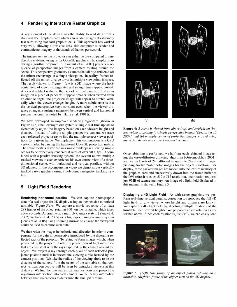
The images sent to the projector can either be pre-computed or ren-dered in real-time using raster OpenGL graphics. The simplest ren-dering algorithm proposed in [Cossairt et al. 2007] projects a se-quence of perspective images from a camera rotating around thescene. This perspective geometry assumes that all rays reflected offthe mirror reconverge at a single viewpoint. In reality, frames re-flected off the mirror diverge towards multiple viewpoints in space.The result (shown in Figure 4 (a)) is a 3D image where the hori-zontal field of view is exaggerated and straight lines appear curved.A second artifact is due to the lack of vertical parallax. Just as animage on a piece of paper will appear smaller when viewed froman oblique angle, the projected image will appear to stretch verti-cally when the viewer changes height. A more subtle error is thatthe vertical perspective stays constant even when the viewer dis-tance changes, causing a mismatch between vertical and horizontalperspective cues (as noted by [Halle et al. 1991]).
We have developed an improved rendering algorithm (shown inFigure 4 (b)) that leverages our system’s unique real-time update todynamically adjust the imagery based on each viewers height anddistance. Instead of using a simple perspective camera, we traceeach reflected projector ray to find the multiple correct viewer posi-tions for a given frame. We implement this computation as a GPUvertex shader, bypassing the traditional OpenGL projection matrix.The entire mesh is rasterized in a single render pass allowing simplescenes to be effectively rendered at rates of over 5000 fps. If com-bined with a passive tracking system, the system allows multipletracked viewers to each experience his own correct view of a three-dimensional scene, with horizontal and vertical parallax, without3D glasses. In the accompanying video we demonstrate verticallytracked raster graphics using a Polyhemus magnetic tracking sys-tem.
5 Light Field Rendering
Rendering horizontal parallax We can capture photographicdata of a real object for 3D display using an inexpensive motorizedturntable (Figure 5(a)). We capture a movie sequence of at least288 frames of the object rotating 360◦ on the turntable, which takesa few seconds. Alternatively, a multiple-camera system [Yang et al.2002; Wilburn et al. 2005] or a high-speed single-camera system[Jones et al. 2006] using spinning mirrors to change the viewpointcould be used to capture such data.
We then rebin the images in the horizontal direction in order to com-pensate for the gain in perspective introduced by the diverging re-flected rays of the projector. To rebin, we form images which, whenprojected by the projector, faithfully project rays of light into spacethat are consistent with the rays captured by the camera around theobject. We project a ray through each pixel of each reflected pro-jector position until it intersects the viewing circle formed by thecamera positions. We take the radius of the viewing circle to be thedistance of the camera from the center of the turntable so that cor-rect vertical perspective will be seen by untracked viewers at thisdistance. We find the two nearest camera positions and project theray/mirror intersection into each camera. We bilinearly interpolatebetween the two cameras to determine the final pixel value.
(a) (b)
Figure 4: A scene is viewed from above (top) and straight-on (be-low) while projecting (a) simple perspective images [Cossairt et al.2007], and (b) multiple-center of projection images warped usingthe vertex shader and correct perspective cues.
Once rebinning is performed, we halftone each rebinned image us-ing the error-diffusion dithering algorithm [Ostromoukhov 2001],and we pack sets of 24 halftoned images into 24-bit color images,yielding twelve 24-bit color images for the object’s rotation. Fordisplay, these packed images are loaded into the texture memory ofthe graphics card and successively drawn into the frame buffer atthe DVI refresh rate. At 512×512 resolution, one rotation requiresjust 9MB of texture memory. An image of a light field displayed inthis manner is shown in Figure 5.
Displaying a 4D Light Field As with raster graphics, we per-form real-time vertical parallax correction to reproduce the full 4Dlight field for any viewer whose height and distance are known.We capture a 4D light field by shooting multiple rotations of theturntable from several heights. We preprocess each rotation as de-scribed above. Since each rotation is just 9MB, we can easily load
Figure 5: (Left) One frame of an object filmed rotating on aturntable. (Right) A frame of the object seen on the 3D display.

twenty or more vertical light field slices into the nVIDIA graphicscard texture memory. While the display is running, we perform dy-namic vertical rebinning that combines photographed images fromdifferent heights to match the viewer’s height and distance. A se-quence of dynamically-rebinned 4D light field imagery displayedfor a tracked camera viewpoint, as well as a visualization of thedynamic light field slices, is shown in the accompanying video.
6 Conclusion
Our display prototype is good for showing small (12cm) objects toa group of people who are looking at the virtual object. The displaycreates an image which appears to hang in space and provides view-ers with an ability to walk anywhere around the object. Our 360◦display creates a light field which exhibits correct horizontal paral-lax anywhere around the display. Occlusion behaves correctly, andthe resolution is sufficient so that one is not even conscious of thetransitions between vertical zones. Novel rendering techniques sup-port real time interactive graphics. We also demonstrated a methodfor capturing and rendering a real object’s light field on the display.Among the significant enabling contributions, we develope requi-site multiple-center-of-projection mathematics for rendering to thedisplay’s convenient form factor, and a unique method of render-ing single-bit imagery at over 5000Hz from a commodity graphicscard. Further mathematical details are available in our SIGGRAPH2007 paper [Jones et al. 2007].
Our goal is to disseminate this system architecture broadly to re-searchers in the field of computer graphics and immersive displays.The core components should continue to decrease in price while in-creasing in capability in line with display and rendering technolo-gies. This system makes it possible to render and display real-time360◦ light fields with a useful number of viewpoints. Such a ca-pability will hopefully allow the pursuit of capturing and renderingmore accurate and realistic models.
Acknowledgements
The authors wish to thank Bruce Lamond, Naho Inamoto, TimHawkins, Pieter Peers, Dell Lunceford, Tom Pereira, Jacki Morie,Sean Bouchard, Bill Swartout, Randy Hill, and Randolph Hall fortheir support and assistance with this work. This work was spon-sored by the University of Southern California Office of the Provostand the U.S. Army Research, Development, and Engineering Com-mand (RDECOM). The high-speed projector was originally devel-oped by a grant from the Office of Naval Research under the guid-ance of Ralph Wachter. The content of the information does notnecessarily reflect the position or the policy of the US Government,and no official endorsement should be inferred.
References
AGOCS, T., BALOGH, T., FORGACS, T., BETTIO, F., GOBBETTI, E., ZANETTI, G.,AND BOUVIER, E. 2006. A large scale interactive holographic display. In VR ’06:Proceedings of the IEEE Virtual Reality Conference (VR 2006), IEEE ComputerSociety, Washington, DC, USA, 57.
BALOGH, T., DOBRANYI, Z., FORGACS, T., MOLNAR, A., SZLOBODA, L., GOB-BETTI, E., MARTON, F., BETTIO, F., PINTORE, G., ZANETTI, G., BOUVIER,E., AND KLEIN, R. 2006. An interactive multi-user holographic environment.In SIGGRAPH ’06: ACM SIGGRAPH 2006 Emerging technologies, ACM Press,New York, NY, USA, 18.
BATCHKO, R. G. 1994. Three-hundred-sixty degree electro-holographic stereogramand volumetric display system. In Proc. SPIE, vol. 2176, 30–41.
CHAI, J.-X., TONG, X., CHAN, S.-C., AND SHUM, H.-Y. 2000. Plenoptic sam-pling. In Proceedings of ACM SIGGRAPH 2000, Computer Graphics Proceedings,Annual Conference Series, 307–318.
COSSAIRT, O., TRAVIS, A. R., MOLLER, C., AND BENTON, S. A. 2004. Novel viewsequential display based on dmd technology. In Proc. SPIE, Stereoscopic Displaysand Virtual Reality Systems XI, A. J. Woods, J. O. Merritt, S. A. Benton, and M. T.Bolas, Eds., vol. 5291, 273–278.
COSSAIRT, O. S., NAPOLI, J., HILL, S. L., DORVAL, R. K., AND FAVALORA, G. E.2007. Occlusion-capable multiview volumetric three-dimensional display. AppliedOptics 46, 8 (Mar), 1244–1250.
DODGSON, N. A. 2005. Autostereoscopic 3d displays. Computer 38, 8, 31–36.
ENDO, T., KAJIKI, Y., HONDA, T., AND SATO, M. 2000. Cylindrical 3d videodisplay observable from all directions. In 8th Pacific Conference on ComputerGraphics and Applications, 300–306.
FAVALORA, G. E. 2005. Volumetric 3d displays and application infrastructure. Com-puter 38, 8, 37–44.
GORTLER, S. J., GRZESZCZUK, R., SZELISKI, R., AND COHEN, M. F. 1996. Thelumigraph. In Proceedings of SIGGRAPH 96, Computer Graphics Proceedings,Annual Conference Series, 43–54.
HALLE, M. W., BENTON, S. A., KLUG, M. A., AND UNDERKOFFLER, J. S. 1991.The ultragram: A generalized holographic stereogram.
HOU, X., WEI, L.-Y., SHUM, H.-Y., AND GUO, B. 2006. Real-time multi-perspective rendering on graphics hardware. In Rendering Techniques 2006: 17thEurographics Workshop on Rendering, 93–102.
ISAKSEN, A., MCMILLAN, L., AND GORTLER, S. J. 2000. Dynamically reparame-terized light fields. In Proceedings of ACM SIGGRAPH 2000, Computer GraphicsProceedings, Annual Conference Series, 297–306.
JONES, A., DEBEVEC, P., BOLAS, M., AND MCDOWALL, I. 2006. Concave sur-round optics for rapid multiview imaging. In Proceedings of the 25th Army ScienceConference.
JONES, A., MCDOWALL, I., YAMADA, H., BOLAS, M., AND DEBEVEC, P. 2007.Rendering for an interactive 360 degree light field display. In ACM Transactionson Graphics.
LEVOY, M., AND HANRAHAN, P. M. 1996. Light field rendering. In Proceedings ofACM SIGGRAPH 96, Computer Graphics Proceedings, Annual Conference Series,31–42.
LIPPMAN, G. 1908. Epreuves reversibles donnant la sensation du relief. Journal ofPhysics 7, 4 (Nov), 821–835.
MAEDA, H., HIROSE, K., YAMASHITA, J., HIROTA, K., AND HIROSE, M. 2003.All-around display for video avatar in real world. In ISMAR ’03: Proceedings ofthe The 2nd IEEE and ACM International Symposium on Mixed and AugmentedReality, IEEE Computer Society, Washington, DC, USA, 288.
OSTROMOUKHOV, V. 2001. A simple and efficient error-diffusion algorithm. InProceedings of ACM SIGGRAPH 2001, Computer Graphics Proceedings, AnnualConference Series, 567–572.
OTSUKA, R., HOSHINO, T., AND HORRY, Y. 2006. Transpost: A novel approachto the display and transmission of 360 degrees-viewable 3d solid images. IEEETransactions on Visualization and Computer Graphics 12, 2, 178–185.
TANAKA, K., AND AOKI, S. 2006. A method for the real-time construction of afull parallax light field. In Stereoscopic Displays and Virtual Reality Systems XIII.Edited by Woods, Andrew J.; Dodgson, Neil A.; Merritt, John O.; Bolas, MarkT.; McDowall, Ian E. Proceedings of the SPIE, Volume 6055, pp. 397-407 (2006).,A. J. Woods, N. A. Dodgson, J. O. Merritt, M. T. Bolas, and I. E. McDowall, Eds.,397–407.
TRAVIS, A. R. L. 1997. The display of three-dimensional video images. Proceedingsof the IEEE 85, 11 (Nov), 1817–1832.
WILBURN, B., JOSHI, N., VAISH, V., TALVALA, E.-V., ANTUNEZ, E., BARTH, A.,ADAMS, A., HOROWITZ, M., AND LEVOY, M. 2005. High performance imagingusing large camera arrays. ACM Transactions on Graphics 24, 3 (Aug), 765–776.
YANG, J. C., EVERETT, M., BUEHLER, C., AND MCMILLAN, L. 2002. A real-timedistributed light field camera. In Rendering Techniques 2002: 13th EurographicsWorkshop on Rendering, 77–86.
YENDO, T., KAWAKAMI, N., AND TACHI, S. 2005. Seelinder: the cylindrical light-field display. In SIGGRAPH ’05: ACM SIGGRAPH 2005 Emerging technologies,ACM Press, New York, NY, USA, 16.
ZWICKER, M., MATUSIK, W., DURAND, F., AND PFISTER, H. 2006. Antialiasingfor automultiscopic 3d displays. In Rendering Techniques 2006: 17th EurographicsWorkshop on Rendering, 73–82.