an intelligent manufacturing system for automatic ...€¦ · functions like costing, process...
TRANSCRIPT

International Journal of Engineering Technology, Management and Applied Sciences
www.ijetmas.com May 2015, Volume 3 Special Issue, ISSN 2349-4476
114 Arunkumar P1, Anand.S.Deshpande2, A.C.S.Kumar3
An Intelligent Manufacturing System for Automatic Extraction
of Product Data from CAD Models having Prismatic Features
Arunkumar P1, Anand.S.Deshpande
2, A.C.S.Kumar
3
1 Associate Professor, Mechanical Engineering, KLS Gogte Institute of Technology, Karnataka,
2 Principal, KLS Gogte Institute of Technology, Karnataka, India,
3 Professor, Mechanical Engineering, JNTU College of Engineering, AP, India,
Abstract
The current manufacturing scenario emphasizes the integration of CAD/CAM with CAPP or other
Computer Aided systems. Feature based technology (FBT) enables this integration. An important
enabler of FBT is the data transferred. This data has to be consistent, should contain geometric and
technological information about the product and should be stored in a format that enables complete
information transfer between different Computer Aided systems. Though STEP format is suited for
this task, the commercially available versions have Application Protocols that do not support
complete transfer of the required technological information which is necessary for industrial
functions like costing, process planning, part programming etc.
Considering these aspects an attempt has been made to develop an intelligent manufacturing
system for components containing various machining features, based on complex object- oriented
coding concepts to capture/transfer data from/to manufacturing & other industrial functions. This
requires technological data validated by product experts to be added into the existing STEP file
which contains only geometric data; thereby resulting in a new file called "STEP+" containing both
geometric as well as technological data, i.e. product data. All the captured/ generated geometric and
technological data is displayed to the user depending on their function and requirement. The output is
in the form of time-cost details for each machining operation, cost estimate for the product, process
plan and part programs for machining.
Keywords: prismatic feature recognition, STEP+, technological data, process planning.
1. INTRODUCTION
For successful CAD/CAM integration, considerable research has been carried out in the area
of Feature Based Technology. This effort has led to the development of two main approaches namely
design-by-features and feature recognition. In the design-by-features approach, part models are
defined directly by adding, subtracting and manipulating features created as instances of predefined
feature types. This approach allows non-geometric information to be stored into the feature model
but limits the designer to the use of pre-defined features, which thus limits the complexity of the
product design that can be represented and making the resulting feature-based model context-
dependent. Feature recognition involves computationally recognizing features from conventional
geometric models or from neutral data format such as IGES or STEP. This approach avoids the
limitation of design-by-features by attempting to identify features from already designed component
description but requires a complex analysis of the geometric model.
2. LITERATURE REVIEW
The basis for good manufacturing systems is the proper recognition of the features in the
component. Various feature recognition methodologies have been proposed in the recent years.
Attempts have been made to recognize features from 2-D representations of the components [1–3].
Convex hull algorithms are used to recognize features from 2.5-D components [4]. 2.5-D features are

International Journal of Engineering Technology, Management and Applied Sciences
www.ijetmas.com May 2015, Volume 3 Special Issue, ISSN 2349-4476
115 Arunkumar P1, Anand.S.Deshpande2, A.C.S.Kumar3
obtained by extruding a 2-D feature along the third direction. Many such 2.5-D features individually
present on different faces as well as intersecting among them result in practical 3-D parts.
Feature recognition endeavors to automatically recognize and extract appropriate features
from a geometrical model. To achieve this, geometric-reasoning techniques are used to interrogate
the data structure of the geometric modeler. The geometric modeler in consideration should usually
be a solid modeler; otherwise the amount of data available in the geometric model may not be
sufficient for the geometric-reasoning process. Substantial research efforts have been expended and
some notable results have been published [5, 6].
Later many feature extraction systems were developed. One of them takes STEP file as input
to define the geometry and topology of a part. In addition, the system generates STEP file, as output
with form feature information is AP224 format for form feature process planning. The STEP file can
be exchanged between various companies and can serve as input to further downstream activities
such as process planning, scheduling and material requirement planning (MRP) [7].
The focus then shifted to Feature-interactions because they have tremendous consequences
on a feature model and its applications, subsequently leading to violation of feature validity, if not
handled properly. Handling feature interactions in feature-based design system is still an unsolved
research issue. Research on feature-interactions in the area of feature-based design approach has had
limited discussion in the literature [8] but has been described widely in feature recognition research
[9]. The research involves analyzing the interaction relationship, decomposing the interacted features
into single features and defining their relationship [10]. Thus, this area of research has become
prominent in feature-based modeling.
Furthermore, the communication between CAD/CAM, CAPP and other CA systems is
necessary to provide transmission of two types of information [11]:
Constructive – (geometric) data, describing design of part.
Technological – data describing way of manufacturing/ machining of part
The combination of the above two types of information constitutes Product Data. The purpose of
STEP is to build a common standard that ensures the product data can be communicated
electronically across different platforms, e.g. CAD, CAM and CAPP. The STEP standard differs
from IGES by incorporating a formal object-oriented model for data exchange [12].
STEP enables all individuals contributing to the design, manufacturing, marketing and supply
of a product and its components to contribute to, to access, and to share information. STEP aims at
eliminating the concept of “islands of automation”. STEP also attempts to unite manufacturing
efforts among corporate partners, distant subsidiaries and suppliers across diverse computer
environments. STEP addresses the issues of diversified engineering applications and covers security
aspects, which become relevant now that several companies would be sharing the same product
information [13].
The STEP neutral file is a text file that contains geometrical data of a component including
boundary representation data such as shells, faces, vertices; surface geometric data such as planes,
cylinders, cones, curve geometric such as lines, circles, ellipses, b-spline curves [14].
The current commercial STEP versions found in commonly available CAD modelers have
AP‟s (AP203) that do not completely support storage/ transfer of technological information. Hence,
taking all these aspects into consideration the present research work has been carried out.
In the research work, STEP (AP 203) containing geometric information about the product has
been used. The Intelligent Feature Recognition System takes this as input, processes it, generates the
Technological information required for the product manufacturing/ machining like time-cost
calculations, process plan part program and other details by taking inputs from Product expert
module, User & validated Knowledge base, finally adds this technological information back to the
International Journal of Engineering Technology, Management and Applied Sciences
www.ijetmas.com May 2015, Volume 3 Special Issue, ISSN 2349-4476
116 Arunkumar P1, Anand.S.Deshpande2, A.C.S.Kumar3
STEP file thereby generating a new file called "STEP+" which contains both Geometric and
Technological data of the product.
3. THE FEATURE RECOGNITION LOGIC
A product model can have any number and types of features. In order to prove the concept,
general types and combinations of features have been considered in the present work. The STEP files
of all these components with features were analyzed and the logic developed for different feature
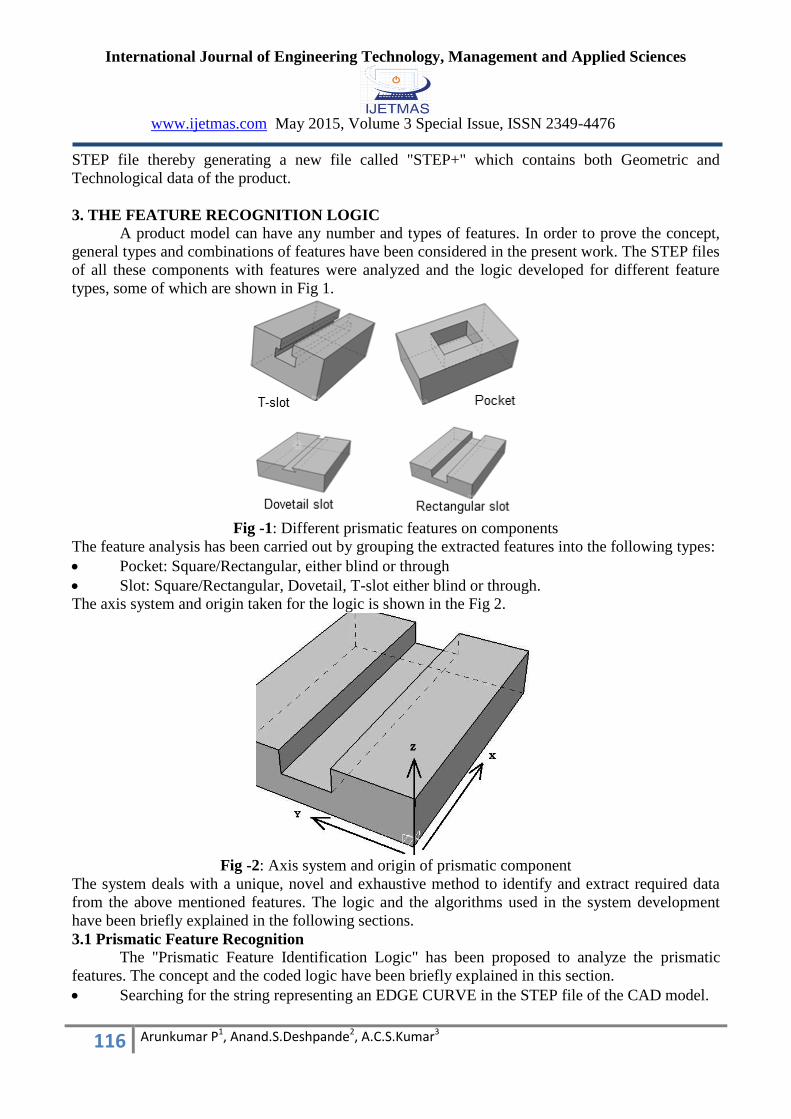
types, some of which are shown in Fig 1.
Fig -1: Different prismatic features on components
The feature analysis has been carried out by grouping the extracted features into the following types:
Pocket: Square/Rectangular, either blind or through
Slot: Square/Rectangular, Dovetail, T-slot either blind or through.
The axis system and origin taken for the logic is shown in the Fig 2.
Fig -2: Axis system and origin of prismatic component
The system deals with a unique, novel and exhaustive method to identify and extract required data
from the above mentioned features. The logic and the algorithms used in the system development
have been briefly explained in the following sections.
3.1 Prismatic Feature Recognition
The "Prismatic Feature Identification Logic" has been proposed to analyze the prismatic
features. The concept and the coded logic have been briefly explained in this section.
Searching for the string representing an EDGE CURVE in the STEP file of the CAD model.

International Journal of Engineering Technology, Management and Applied Sciences
www.ijetmas.com May 2015, Volume 3 Special Issue, ISSN 2349-4476
117 Arunkumar P1, Anand.S.Deshpande2, A.C.S.Kumar3
Analysis of the string, character-by-character to find the hash codes corresponding to Vertex
points thereby leading to the Cartesian points.
Identification of the edges forming part of the feature. This is done by eliminating the edges
which have minimum and maximum coordinate values in X, Y and Z directions.
Identification of the line type viz. horizontal, vertical or inclined.
Inferring the relationship between the lines e.g. parallel or perpendicular, equal or unrelated.
Recognition of the prismatic feature is carried out by the Edge theory.
The Maximum values of X, Y and Z indicate the length, width and height of the plate.
If length of slot = Length of Plate, it is a through slot, else blind.
The feature recognition logic for t-slot in addition to identifying other prismatic features has been
shown in the flowchart form in Fig 3.
Fig -3: Flowchart showing Feature Recognition Logic for Prismatic features

International Journal of Engineering Technology, Management and Applied Sciences
www.ijetmas.com May 2015, Volume 3 Special Issue, ISSN 2349-4476
118 Arunkumar P1, Anand.S.Deshpande2, A.C.S.Kumar3
4. A FEATURE BASED INTELLIGENT MANUFACTURING SYSTEM
The system comprises of three well
integrated modules:
i. Intelligent feature recognition
System
ii. Product Expert module
iii. Operation Scheduling module
The workflow of the system is shown in
Fig 4. The CAD model for the required
part is created & the STEP file (AP 203)
is extracted. This file is then analyzed by
the intelligent feature recognition system
which identifies & extracts the
machining features in the model. The
output is a graphic representation of the
feature along with geometric data like
dimensions of the model, volume, weight
etc. To give this type of information,
technological data is also needed.
This data is authenticated & fed
into the system by the Product Expert
module which has access to all data
related to Overhead costs, Tool Database
& Parameters, Machine Database,
Customer Database, Cutting Speed and
Feed data based on machine capabilities.
This data is collected from user input as
well as a reliable & validated Knowledge
base of technological data. Thus the file
that has geometric as well as
technological data is now termed “STEP
+” file in the present work. The output/
reports generated cater to all functions of
industry. Cost estimates, workshop
capacity including DB of machines &
tools, process planning, part programs
have been the outputs of this system.
Fig -4: System Workflow
5. THE INTELLIGENT MANUFACTURING SYSTEM
Many components containing features like prismatic, rotational, free form, interaction of
prismatic-rotational etc., have been taken for the research work. However, in this paper the
component having prismatic pocket feature has been considered (Fig 5). With respect to this, the
flow of the intelligent manufacturing system to generate the required output has been explained with
the help of screenshots.

International Journal of Engineering Technology, Management and Applied Sciences
www.ijetmas.com May 2015, Volume 3 Special Issue, ISSN 2349-4476
119 Arunkumar P1, Anand.S.Deshpande2, A.C.S.Kumar3
Fig -5: Sample component with prismatic features
In Fig 6, the decoded STEP file of a component containing prismatic pocket feature is shown.
It contains the geometric data w.r.t Cartesian points and their X, Y, Z values.
Fig -6: STP File processing
Fig 7 depicts the details of the object including dimensions of individual features along with
volume, density & weight. The material type & density values are taken from Product expert
database.
The details of the manufacturing processes and their sequence, needed for the feature is
displayed to the user based on the technological information submitted by user in the form of Process
Capabilities (Table 1). The values entered are compared with standard values of machining processes
available in the database and the suitable processes are recommended, when the "View Processes"
button gets activated.
Table -1: Process capabilities of Milling
International Journal of Engineering Technology, Management and Applied Sciences
www.ijetmas.com May 2015, Volume 3 Special Issue, ISSN 2349-4476
120 Arunkumar P1, Anand.S.Deshpande2, A.C.S.Kumar3
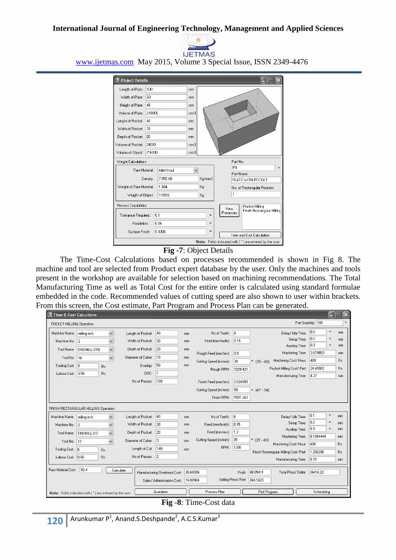
Fig -7: Object Details
The Time-Cost Calculations based on processes recommended is shown in Fig 8. The
machine and tool are selected from Product expert database by the user. Only the machines and tools
present in the workshop are available for selection based on machining recommendations. The Total
Manufacturing Time as well as Total Cost for the entire order is calculated using standard formulae
embedded in the code. Recommended values of cutting speed are also shown to user within brackets.
From this screen, the Cost estimate, Part Program and Process Plan can be generated.
Fig -8: Time-Cost data
International Journal of Engineering Technology, Management and Applied Sciences
www.ijetmas.com May 2015, Volume 3 Special Issue, ISSN 2349-4476
121 Arunkumar P1, Anand.S.Deshpande2, A.C.S.Kumar3
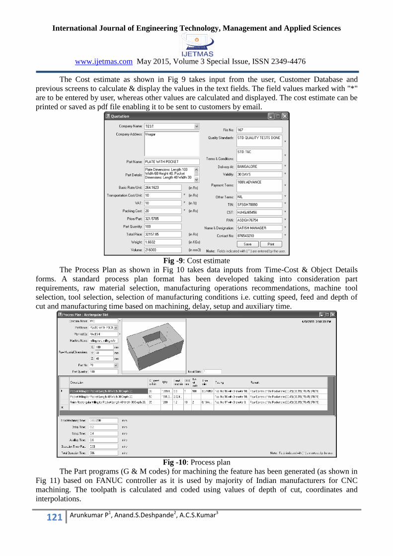
The Cost estimate as shown in Fig 9 takes input from the user, Customer Database and
previous screens to calculate & display the values in the text fields. The field values marked with "*"
are to be entered by user, whereas other values are calculated and displayed. The cost estimate can be
printed or saved as pdf file enabling it to be sent to customers by email.
Fig -9: Cost estimate
The Process Plan as shown in Fig 10 takes data inputs from Time-Cost & Object Details
forms. A standard process plan format has been developed taking into consideration part
requirements, raw material selection, manufacturing operations recommendations, machine tool
selection, tool selection, selection of manufacturing conditions i.e. cutting speed, feed and depth of
cut and manufacturing time based on machining, delay, setup and auxiliary time.
Fig -10: Process plan
The Part programs (G & M codes) for machining the feature has been generated (as shown in
Fig 11) based on FANUC controller as it is used by majority of Indian manufacturers for CNC
machining. The toolpath is calculated and coded using values of depth of cut, coordinates and
interpolations.

International Journal of Engineering Technology, Management and Applied Sciences
www.ijetmas.com May 2015, Volume 3 Special Issue, ISSN 2349-4476
122 Arunkumar P1, Anand.S.Deshpande2, A.C.S.Kumar3
Fig -11: Part program
6. SCHEDULING MODULE
The Scheduling of Operations for any part is carried out in the “Scheduling Module”
provided in the Main GUI screen as shown in Fig 12. The machine no, tool no, manufacturing time
of each operation is stored in DB when the time cost calculations are done. The time has to be
selected for scheduling of an operation, depending on the availability of the slot either the operation
will be scheduled or the machine status will be displayed as „busy‟.
Another feature called the "Machine Status chart" has been provided which displays the
status of the machine at any point of time. The machine status (engaged/ free) can be observed in the
status chart as shown in Fig 13. The ticks in the check boxes indicate the engaged slots whereas the
blank check boxes indicate the free slots. This can be taken as a basis for optimal capacity utilization
on the shop floor.
Fig -12: Scheduling the operations in respective machines & specifying the operation start time
Fig -13: Viewing the machine/ work status

International Journal of Engineering Technology, Management and Applied Sciences
www.ijetmas.com May 2015, Volume 3 Special Issue, ISSN 2349-4476
123 Arunkumar P1, Anand.S.Deshpande2, A.C.S.Kumar3
7. STEP+ FILE
The geometric data in the STEP (AP203) input file is added with the technological data
generated from the intelligent system, product expert & the user. The result is a new file called
“STEP+” file, which contains both geometric & technological data. A sample STEP+ file is shown in
Fig 14.
The STEP+ file contains the following data:
Entire Geometric data of the part contained in STEP file
Object/ feature dimensions
Process sequence
Time-Cost data of each operation
Machine and Tool data
Machining parameters like Cutting Speed, Feed, DOC etc.
Fig -14: Sample „STEP+‟ File containing geometric & technological data for a component
This can be seen as a platform for future works in the field of Product Lifecycle Management (PLM)
as the entire product data is available in a single master file.
CONCLUSIONS
The work has led to the design and development of an Intelligent Feature based
Manufacturing system with a focus on general and commonly observed product manufacturing
environment and procedures. The part programs generated from the system have been executed on
Fanuc controlled CNC machines and no errors; either in the syntax or logic have been found. The
geometric dimensions on the machined parts were found to match the values given in the CAD
model. The part programs and process plans are found to be compatible with real life manufacturing
environment.
ACKNOWLEDGEMENT
We profoundly thank AICTE, New Delhi for funding the research work by providing the
RPS grant. We also thank the Management, KLS Gogte Institute of Technology for providing the
funds and infrastructure to setup Computer Integrated Manufacturing lab used in conducting the
research work.

International Journal of Engineering Technology, Management and Applied Sciences
www.ijetmas.com May 2015, Volume 3 Special Issue, ISSN 2349-4476
124 Arunkumar P1, Anand.S.Deshpande2, A.C.S.Kumar3
REFERENCES
[1]. Meeran S, Pratt MJ, Kay J. The use of PROLOG in the automatic recognition of manufacturing
features from 2-D drawings. Eng Application Artificial Intelligence 1993; 6(5):409–23.
[2]. Meeran S, Pratt MJ. Automated feature recognition from 2D drawings. Computer Aided Design
1993; 25(1):7–17.
[3]. Meeran S, Taib JM. A generic approach to recognizing isolated, nested and interacting features
from 2Ddrawings. Computer Aided Design 1999; 31(14):891–910.
[4]. Ferreira JCE, Hinduja S. Convex hull-based feature-recognition method for 2.5D components.
Computer Aided Design 1990; 22(1):41–9.
[5]. M.R. Henderson, Extraction of feature information from three-dimensional CAD data, Ph.D.
Thesis, Purdue University, 1984.
[6]. A.R. Grayer, The automatic production of machined components starting from a stored
geometric description, in D. McPherson (Ed.), Advances in Computer Aided Manufacturing,
North-Holland, Amsterdam, (1977) pp. 137 151.
[7]. Bhandarkar, M. P. and Nagi, R. (2000). STEP-based feature extraction from STEP geometry for
agile manufacturing, Computers in Industry, 41, pp. 3-24.
[8]. Su,C.J., Sun.T.L., Wu,C.N. and Mayer,R.J., An Integrated Form-Feature-Based Design System
for Manufacturing, Journal of Intelligent Manufacturing, 1995, 6, 277-290.
[9]. Narang,R.V., An Application Independent Methodology of Feature Recognition with Explicit
Representation of Feature Interaction, Journal of Intelligent Manufacturing, 1996, 7, 479-486.
[10]. Suh,H. And Ahluwalia,R.S., Feature Modification in Incremental Feature Generation,
Computer-Aided Design, 1995, 27, 627-635.
[11] Stroka, R. and Helis, A., Integration of CAPP and CAD/CAM Systems, International Workshop
on CA Systems and Technologies, 2001.
[12]. Trappey, A. J. C. and Chang, C. R., ISO 10303-compliant computer-aided wheel rim design
system- the framework and data model, International Journal of Production Research, 2000,
28(6), 1325-1338.
[13]. Lau, H. and Jiang, B., A generic integrated system from CAD to CAPP: a neutral file-cum-GT
approach, Computer Integrated Manufacturing System, 1998, 11(1/2), 67-75.
[14]. Liang, M., Ahamad, S. and van den Berg, B., A STEP based tool path generation system for
rough machining of planar surfaces, Computers in Industry, 1996, 32, 219-231.