an integrated collaborative environment for materials research
TRANSCRIPT

Integrity Service Excellence
An Integrated Collaborative Environment for Materials
Research
Matthew JacobsenMaterials & Manufacturing Directorate

Presentation Roadmap
•Introduce ICE•Review integration case•Present a vision for the future of ICE and like systems

Acknowledgements
• Dr. Charles Ward• Bryon Foster • The rest of the team

High Energy Diffraction Microscopy
Materials and ManufacturingResearch Infrastructure
• 700+ scientists and engineers• 108,000 sq ft lab space, 200 lab modules• 750+ computers associated with research equipment• 1000+ computers on desks: 2 separate networks• 80+ scientific and engineering software packages• Local computational clusters & remote HPC
And no supporting collaborative research environment
Materials Characterization Facility
DSRC Lightning
4

An Integrated Collaborative Environment
• ICE is a highly tailored, federated infrastructure built for the R&D community
• ICE represents a joint effort between software and materials engineers to deliver game-changing functionality
• The Materials Genome Initiative (MGI) calls for a Materials Innovation Infrastructure, in agreement with the goals of ICMSE
5

ICE‐Enabled Capabilities
• The coordination and management of research activities
• The collection of research data (structured and unstructured)
• Complete traceability of material evolution
• Legacy data sources to continue to exist in many cases, but with connections to ICE API
• Growth of the RX ICMSE culture

Federated Concept
• The Federated Architecture allows for self-governance of connected systems
• Systems may be COTS tools, in-house developed applications, or any hybrid thereof
• Systems do not talk directly to each other - ICE “brokers” all transactions between connected systems
7

Architectural Solution
• ICE Core - Collaboration platform (Hub), Common Service Bus and Apps(Django), advanced visualization (Plotly)
• ICE Extended - Material properties database (Granta), MTS Echo, Dream.3D
• Persistent identification, triple-based metadata, data type registration and SSO
• Graphical workflow design tools, item management, file management, advanced search tools 8

Detailed Design & Behaviors
9
Step 1:File Upload
data.csv
Step 2:API Call for
PID Issuance
Step 3:Metadata and
Location Registered
Metadata
Step 4:PID Issued/File Saved Locally
Case 1: PID Stored Locally
Step 1:Create Record
Material Record
Step 2:API call to Notify ICE
Step 3:Metadata, Local ID and Location Registered
Case 2: PID Linked to Local IDCase 3: Searching/Querying Data
Step 1:Search Terms
Entered
Step 3:Endpoints Determined for PIDs with Metadata
Matching Terms
Step 4:Endpoints Called to
Return Data
Step 2:API Call for PID Search
Step 5:API Returns Data to Interface
Location

Data Creation via Workflow
10

Data Retrieval via Search
11

System Connection
• Test case – U of M’s Materials Commons• Add Materials Commons API to ICE.Search
– ICE delegates search mechanism to Materials Commons
– Materials Commons relies on Elasticsearch (full text) vs object search (ICE.Search)
• Connection established after 4 hours of collaboration– RESTful call with authentication token and search string
– JSON returned, shaped into search result format
12

Search Extended to Materials Commons
13

Object Instantiation
• Persistent Problem – how to treat workflow processes, participants, and items (physical and digital) as first class objects?
• Begin to register various data types – object “classes”
• Ex. Tension test, titanium specimen, etc.• Invoke registered data types wherever possible• Index all metadata assignments based on object type
14

New Functionality
• Data Model Builder – open up the DTR to certain users
• Graphical interface for defining data models and linkages/nesting
• DTR is implemented with OO principles of inheritance
• Use a NoSQL structure to define “parent” classes (casting) and child classes (investment casting)
• Restrict instantiation of new objects (even metadata) to those entries in the DTR.
15

Example 1 – Data Model Builder
16
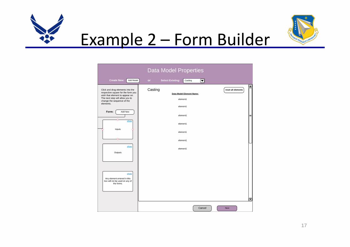
Example 2 – Form Builder
17

An Improvement, but…
• Still not “semantic” – how do we relate our classes?
• We need a simple way (baby steps) to start building vocabularies, taxonomies, and domain‐specific ontologies
• Our users are overwhelmed at the utterance of “ontology”
• Enter the Basic Formal Ontology
18

Basic Formal Ontology
• Created by Dr. Barry Smith and others circa 2000
• Establishes a high level framework for building out domain ontologies
• Successfully used in biomedicine, human genome project, Army, etc.
• Extended by “common core” ontologies, and further in domain specific ontologies
19

BFO High Level
20
• Try to abstract objects from processes (test frame from the test for example) and use “occurents” only as needed
• Most things can and should be described as continuants• Separate objects from qualities/properties

Approach
• Whiteboard a concept
• Build a taxonomy
• Define relationships
• Construct domain ontology from taxonomy and relational elements
• Continuously refine the ontology
• Propagate into other domains
21

Example – Tension Test
22
• First stab – not perfect, but gives plenty of elements to start fitting into a taxonomy• Key point – the SME must be involved and be comfortable with the flow

Taxonomy and Relationships
• Materials
• Metals
• Stainless Steel
• Non-Metals
• …..
• Quality
• Porosity
• Density
• Transmittance
• ….
• Relationships
• Participates in
• Contains
23
• Systems like Granta do this pretty well already• Downside is that the qualities are dependent
• Object instances pull from all tiers:-Ex: Sample of Stainless Steel has qualities X, Y, Z,and was part of Test A• Qualities are only invoked in the instance,
not the class

Value Proposition
• System integration is greatly enhanced by using common schema/vocabulary/ontology
• Eases total ecosystem burden with standard models/classes
• Existing schema/ontology momentum in many S&T communities
24

Next steps
• Engage SMEs and flesh out the mechanical test domain
• Build into BFO domain ontology in Protégé
• Flatten out the taxonomy and ontology
• Build an inferencing engine for determining identities based solely on qualities, similar to a graph-based templating search
• Implement common domain elements in partnering systems
• We need to collaborate!!25

26