an improvement strategy on direction cosine matrix based ...the original dcm imu estimation method...
TRANSCRIPT

Global Journal of Researches in Engineering: FElectrical and Electronics Engineering Volume 14 Issue 8 Version 1.0 Year 2014Type: Double Blind Peer Reviewed International Research JournalPublisher: Global Journals Inc. (USA)Online ISSN: 2249-4596 & Print ISSN: 0975-5861
An Improvement Strategy on Direction Cosine Matrix based Attitude Estimation for Multi-Rotor Autopilot By Nazia Ahsan Dilshad & Mohammed Kawser Jahan American International University, Bangladesh
Abstract- In present days, autonomous multi-rotor copters are increasingly becoming popular due to its advantages in terms of multi-purpose functionalities, robustness, high dynamic response and more significantly inexpensive costs of development and usage. However, real-time attitude estimation is a key component which needs to have further development for better control and precise navigation to drive these unmanned aerial vehicles reliably. This paper presented an approach to improve the method of attitude estimation by Direction Cosine Matrix for multi-rotor copters that is based on low cost MEMS inertial sensors, a magnetometer and a commercial GPS receiver. In connection with the Direction Cosine Matrix attitude estimation scheme, a novel algorithm design for dealing with limitations on attitude sensing accuracy and reducing latency in real-time is proposed. The design is insensitive to noise or loss of GPS signals. The viability of the proposed design is demonstrated by an experimental scenario with real-time attitude information under different observations. From the experiment, some issues have been noticed and their reasons have been discussed.
GJRE-F Classification : FOR Code: 090699
AnImprovementStrategyonDirectionCosineMatrixbasedAttitudeEstimationforMultiRotorAutopilot
Strictly as per the compliance and regulations of :
© 2014. Nazia Ahsan Dilshad & Mohammed Kawser Jahan. This is a research/review paper, distributed under the terms of the Creative Commons Attribution-Noncommercial 3.0 Unported License http://creativecommons.org/licenses/by-nc/3.0/), permitting all non commercial use, distribution, and reproduction in any medium, provided the original work is properly cited.
Index Terms: attitude estimation, unmanned aerial vehicle, VTOL, RC aircraft, multi rotor copter, hover, MEMS, IMU, DCM, roll, pitch, yaw, euler angles, autopilot, gyro bias, gyro drift, accelerometer, magnetometer, calibration iron distortion, tilt compensation, normalization.

An Improvement Strategy on Direction Cosine Matrix based Attitude Estimation for Multi-Rotor
Autopilot Nazia Ahsan Dilshad α & Mohammed Kawser Jahan σ
Abstract- In present days, autonomous multi-rotor copters are increasingly becoming popular due to its advantages in terms of multi-purpose functionalities, robustness, high dynamic response and more significantly inexpensive costs of development and usage. However, real-time attitude estimation is a key component which needs to have further development for better control and precise navigation to drive these unmanned aerial vehicles reliably. This paper presented an approach to improve the method of attitude estimation by Direction Cosine Matrix for multi-rotor copters that is based on low cost MEMS inertial sensors, a magnetometer and a commercial GPS receiver. In connection with the Direction Cosine Matrix attitude estimation scheme, a novel algorithm design for dealing with limitations on attitude sensing accuracy and reducing latency in real-time is proposed. The design is insensitive to noise or loss of GPS signals. The viability of the proposed design is demonstrated by an experimental scenario with real-time attitude information under different observations. From the experiment, some issues have been noticed and their reasons have been discussed.
i. INTRODUCTION
Author α σ: Department of Electrical and Electronic Engineering American International University – Bangladesh, Dhaka, Bangladesh. e-mails: [email protected], [email protected]
The DCM is the matrix of
rotation between a Cartesian coordinate frame, which is rigidly fixed in the aircraft body, and a reference Cartesian coordinate frame. This matrix is also known as rotation matrix (denoted by R)
[1]. The DCM is a 3×3 matrix, whose nine elements are not independent. Like any rotation matrix, DCM is a proper orthogonal matrix, which implies six constraints connecting the nine elements. In spite of the redundancy created by the constraints, the DCM is a convenient rotation representation because the equations that describe the vector measurement model and the aircraft kinematical model are linear in DCM [1]. The DCM IMU estimation is a popular attitude estimation method that has been developed for model airplanes by William Premerlani and Paul Bizard
[2]. According to this method a rate gyro is required to derive attitudes by integrating the rigid body kinematic equations, accelerometer is required to provide gravity direction and GPS is essential to get the YAW reference.
This paper is organized as follows. Section III addresses
the problem definition.
Section IV
describes the improvement strategy on DCM based attitude estimation for multi-rotor autopilot which includes
Globa
l Jo
urna
l of
Resea
rche
s in E
nginee
ring
()
FVolum
e X
IV
Issu
e V
III V
ersion
I
23
Year
2014
© 2014 Global Journals Inc. (US)
Index Terms: attitude estimation, unmanned aerial vehicle, VTOL, RC aircraft, multi rotor copter, hover,MEMS, IMU, DCM, roll, pitch, yaw, euler angles, autopilot, gyro bias, gyro drift, accelerometer, magnetometer, calibration iron distortion, tilt compensation, normalization.
hese days unmanned flying robots or unmanned aerial vehicles (UAVs) are gaining popularitybecause of their wide range of applications. One
type of UAV with a strong potential for both indoor and outdoor applications, is the multi-rotor copter. This special type of rotorcraft has the capability of vertical takeoff and landing (VTOL), as well as the ability to achieve rapid and stable motion in every direction. For these characteristics, multi-rotorcraft is suitable forhands-off autonomous operation within cluttered environments such as small buildings or caves and has many applications including surveillance, search and rescue, exploration in hazardous
T
in autopilot module for controlling multi-rotorcraft is the most critical challenge that engineers face whiledeveloping such aircraft. The attitude estimator is widely known as inertial measurement unit (IMU). Low-cost IMU systems are mainly based on micro-electro-mechanical systems (MEMS) technology. A typical IMU is equipped with 3-axis accelerometers, 3-axis rate gyroscopes and 3-axis magnetometers. Due to the limitations in sensing technologies and embedded processing, an IMU system cannot perform with zero error. Developing the control law with a better attitude estimating method can effectively improve the system performance and flight stability. Several attitude estimation methods have been developed in this research field, and direction cosine matrix (DCM) based attitude estimation is one of them. An improvement strategy on this estimation method is depicted in this paper.
by human command, and therefore autopilot system with suitable control algorithm is required to make them stable. However, building a real-time attitude estimator coordinate system modification, step by step formation
of rotation matrix for the modified coordinate systems, experimental analysis on using magnetometer-heading instead of GPS-heading, discussion on magnetometer error compensation and fusing reference vectors from

GPS, and development of a new
attitude estimation algorithm.
The experimental
results
and analysis on
the developed system are presented and discussed in Section V to validate and evaluate the system’s usability.
ii.
NOMENCLATURE
Some of the notations which have been
used in this paper to understand the mechanical and mathematical relationships are presented in this section:
DCM: Direction Cosine Matrix
KF: Kalman Filter
EKF: Extended Kalman Filter
QUEST: Quaternion Estimator
GPS: Global Positioning System
CG: Center of gravity
FPU: Flight Processing Unit
IMU: Inertial Measurement Unit
PID: Proportional Integral Derivative
YAW: Twist or oscillation about a vertical axis
VTOL: Vertical takeoff and landing
Attitude: Roll, pitch and yaw
Heading: Aircraft’s nose direction
R: Rotation Matrix
φ: Roll angle
θ: Pitch angle
ψ: Yaw angle
ω: Angular Rate Vector
W: Gyro sensor readings
𝑅𝑅𝑒𝑒: Earth
frame, which is attached to the ground
𝑥𝑥𝑒𝑒 ,𝑦𝑦𝑒𝑒 ,𝑧𝑧𝑒𝑒 : Axes of earth frame
𝑅𝑅𝑏𝑏 : Body fixed frame, which is attached to the aircraft
𝑥𝑥𝑏𝑏 ,𝑦𝑦𝑏𝑏 , 𝑧𝑧𝑏𝑏 : Axes of body fixed frame
(𝑋𝑋,𝑌𝑌,𝑍𝑍)𝑀𝑀𝑀𝑀𝑀𝑀 : Measured values of X,
Y,
Z axes
(𝑋𝑋,𝑌𝑌,𝑍𝑍)𝐶𝐶𝐶𝐶𝑀𝑀𝐶𝐶 : Compensated values of X,
Y,
Z axes
𝜔𝜔𝑥𝑥 : Angular rate on x-axis in 𝑅𝑅𝑏𝑏 -frame
𝑎𝑎𝑥𝑥 : Acceleration on x-axis in 𝑅𝑅𝑏𝑏 -frame
I3: 3 × 3 Identity matrix
iii.
PROBLEM DEFINITION
In real world,
the original technique of DCM
based attitude estimation suffers
some unavoidable problems. As any of these problems can cause occasional malfunctions,
it cannot be used as a
standalone process without support from a strong
attitude data from gyroscope which includes angles of roll, pitch and
yaw. As gyroscope drifts
over long time
periods, it is necessary to take reference attitude data repeatedly to minimize its errors before calculating the final flight angles. So the accelerometer is used to get the reference vector of roll and pitch
and
the GPS is used
to get the reference vector of yaw. GPS signal availability
is essential for running the whole process because the
IMU will lose its track over time without GPS. Since the
transient response of GPS is not fast enough, the original
technique of DCM based attitude estimation is not suitable for VTOL aircrafts. VTOL aircrafts are dynamically very
sensitive along their yaw axis and this
makes controlling the movement along yaw axis very hard. It is not possible to overcome
this issue with any
slow process like GPS. Magnetometer is a device for locating the direction of earth’s
magnetic poles with
faster transient response than GPS system. So it can be used as the reference sensing element for yaw movement in VTOL aircraft. But in most cases, output data from magnetometer has offset values so using this device cannot help the estimation process with accurate data
like GPS.
Magnetometer outputs true values of
earth's magnetic field only when it stays parallel to the ground and that means magnetometer will give wrong orientation data when
the aircraft
stays
tilted to the
ground. Also, magnetometer data gets distorted because of
the nearby
power lines
as erroneous data will
be produced if magnetometer cannot distinguish earth’s true magnetic field due to interference of
external
magnetic and electric fields. In today’s market, the coordinate system
followed by
the orientation sensing devices does not match with the conventional coordinate system used in
the original DCM IMU estimation method and this will cause inconvenience
for any autopilot system developer.
Another drawback of this method is that it takes a lot of time to process the output.
DCM based attitude estimation method is more stable and provides accurate result than any
other
method. But still it is not suitable for multi-rotor crafts due
to the
issues
mentioned
above. So improving its methodology is necessary to use it for multi-rotor
crafts.
iv.
IMPROVEMENT STRATEGY
The objective of improving the DCM based
attitude estimation process by developing
its algorithm to
the next level of advancement is to make it suitable to
use in real-time control processor of any autopilot module of multi-rotorcraft. The
step-by-step development
approaches are described below.
a)
Coordinate System Modification
The conventional coordinate system that was used to develop the rotation matrix of DCM IMU algorithm consists of
two Cartesian coordinate frames,
An Improvement Strategy on Direction Cosine Matrix based Attitude Estimation for Multi-Rotor Autopilot
Globa
l Jo
urna
l of
Resea
rche
s in E
nginee
ring
(
)F
Volum
e X
IV
Issu
e V
III V
ersion
I
24
Year
2014
© 2014 Global Journals Inc. (US)
reference. The initial task of this process is to gather raw as shown in figure 1, one frame (𝑥𝑥𝑏𝑏 ,𝑦𝑦𝑏𝑏 ,𝑧𝑧𝑏𝑏 ) is rigidly fixed

to the aircraft body, and the other one (𝑥𝑥𝑒𝑒 ,𝑦𝑦𝑒𝑒 ,𝑧𝑧𝑒𝑒 )
is the
earth’s frame of
reference.
Fig.1 :
The
conventional coordinate system [2]
In conventional coordinate system the 𝑥𝑥𝑏𝑏
and 𝑥𝑥𝑒𝑒
axes, 𝑦𝑦𝑏𝑏 and
𝑦𝑦𝑒𝑒
axes, and 𝑧𝑧𝑏𝑏
and
𝑧𝑧𝑒𝑒
axes are directed
towards forward, right, and downward
direction respectively. If both the frames are rotated 180 degree
along forward axis then the coordinate system will match with the coordinate system followed
by
the commercially
available IMU hardware. So the inertial axes about the centre of gravity (CG)
of aircraft body
are:
•
𝑥𝑥𝑏𝑏 axis - positive forward
•
𝑦𝑦𝑏𝑏 axis - positive to left, perpendicular to 𝑥𝑥𝑏𝑏
axis
•
𝑧𝑧𝑏𝑏 axis - positive upwards, perpendicular to 𝑥𝑥𝑏𝑏 -𝑦𝑦𝑏𝑏
plane
According to the Euler theorem, the orientation of the aircraft body fixed frame (𝑅𝑅𝑏𝑏 ) with respect to the earth fixed frame (𝑅𝑅𝑒𝑒) can be described by three consecutive rotations of 𝑅𝑅𝑏𝑏 along each of its axis, whose order is arbitrary, but the same axis may not be used twice in succession. The rotation sequences are usually denoted by three numbers, 1 for x-axis of 𝑅𝑅𝑏𝑏 , 2 for y-axis of 𝑅𝑅𝑏𝑏 , and 3 for z-axis of 𝑅𝑅𝑏𝑏 . Among the twelve valid rotation sequences, we have proposed to choose the rotation sequence 132 or x−z−y for obtaining the attitude of aircraft in modified coordinate system. So the three consecutive rotations have been accomplished in the following order, assuming that the aircraft is initially positioned in such a way that the body frame is parallel to the earth frame:
• Rotating the body about 𝑥𝑥𝑏𝑏 axis through roll angle (φ)
• Rotating the body about 𝑧𝑧𝑏𝑏 axis through yaw angle (-ψ)
• Rotating the body about 𝑦𝑦𝑏𝑏 axis through pitch angle (-θ)
Fig. 2 : The modified coordinate system
b) Rotation Matrix Formation
In the previous section, the rotation sequence that has been proposed is the 132 or x−z−y. So considering a rotation from F reference frame to F''' reference frame, the first rotation that is illustrated in Fig. 3, is about x-axis through an angle 𝜃𝜃𝑥𝑥
which is positive according to the right hand rule about the x-axis. With two rotations to go, the resulting alignment in general is oriented with neither of F or F''', but some intermediate reference frame (the first of two) denoted F'. Since the rotation was about x, x' is parallel to it but neither of the other two primed axes are.
zz’
y’
yθx
θx
Fig 3 : Anti-clockwise rotation from the reference frame F to F'
Now to describe this rotation, we can write:
�𝐹𝐹𝑥𝑥′𝐹𝐹𝑦𝑦′𝐹𝐹𝑧𝑧′
� = �cos𝑥𝑥𝑥𝑥 ′ cos𝑥𝑥𝑦𝑦′ cos𝑥𝑥𝑧𝑧′cos𝑦𝑦𝑥𝑥 ′ cos𝑦𝑦𝑦𝑦′ cos𝑦𝑦𝑧𝑧′cos𝑧𝑧𝑥𝑥 ′ cos𝑧𝑧𝑦𝑦′ cos𝑧𝑧𝑧𝑧′
� �𝐹𝐹𝑥𝑥𝐹𝐹𝑦𝑦𝐹𝐹𝑧𝑧�
= �cos 0𝑜𝑜 cos 90𝑜𝑜 cos 90𝑜𝑜
cos 90𝑜𝑜 cos𝜃𝜃𝑥𝑥 cos(90𝑜𝑜 + 𝜃𝜃𝑥𝑥)cos 90𝑜𝑜 cos(90𝑜𝑜 − 𝜃𝜃𝑥𝑥) cos𝜃𝜃𝑥𝑥
� �𝐹𝐹𝑥𝑥𝐹𝐹𝑦𝑦𝐹𝐹𝑧𝑧�
∴ �𝐹𝐹𝑥𝑥′𝐹𝐹𝑦𝑦′𝐹𝐹𝑧𝑧′
� = �1 0 00 cos𝜃𝜃𝑥𝑥 − sin𝜃𝜃𝑥𝑥0 sin𝜃𝜃𝑥𝑥 cos𝜃𝜃𝑥𝑥
��𝐹𝐹𝑥𝑥𝐹𝐹𝑦𝑦𝐹𝐹𝑧𝑧� = 𝑅𝑅𝑥𝑥(𝜃𝜃𝑥𝑥) (1)
The next rotation that is shown in Fig. 4, is through an angle −𝜃𝜃𝑧𝑧 about the z'-axis of the first intermediate reference frame to the second intermediate
An Improvement Strategy on Direction Cosine Matrix based Attitude Estimation for Multi-Rotor Autopilot
Globa
l Jo
urna
l of
Resea
rche
s in E
nginee
ring
()
FVolum
e X
IV
Issu
e V
III V
ersion
I
25
Year
2014
© 2014 Global Journals Inc. (US)

reference frame, F''. Angle 𝜃𝜃𝑧𝑧 is negative according to the right hand rule about the z-axis. Note that z'' = z', and neither x'' or z'' are necessarily axes of either F or F'''.
-θz
-θz
y’ y’’
x’
x’’
Fig. 4 : Clockwise rotation from the reference frame F' to F''
For this rotation, we can write:
�𝐹𝐹𝑥𝑥′′𝐹𝐹𝑦𝑦′′𝐹𝐹𝑧𝑧′′
� = �cos𝑥𝑥 ′ 𝑥𝑥 ′′ cos𝑥𝑥 ′ 𝑦𝑦′′ cos𝑥𝑥 ′ 𝑧𝑧 ′′cos𝑦𝑦′ 𝑥𝑥 ′′ cos𝑦𝑦′ 𝑦𝑦′′ cos𝑦𝑦′ 𝑧𝑧 ′′cos𝑧𝑧′ 𝑥𝑥′′ cos𝑧𝑧′ 𝑦𝑦′′ cos𝑧𝑧′ 𝑧𝑧 ′′
� �𝐹𝐹𝑥𝑥′𝐹𝐹𝑦𝑦′𝐹𝐹𝑧𝑧′
�
= �cos(−𝜃𝜃𝑧𝑧) cos(90𝑜𝑜 − 𝜃𝜃𝑧𝑧) cos 90𝑜𝑜
cos(90𝑜𝑜 + 𝜃𝜃𝑧𝑧) cos(−𝜃𝜃𝑧𝑧) cos 90𝑜𝑜cos 90𝑜𝑜 cos 90𝑜𝑜 cos 0𝑜𝑜
� �𝐹𝐹𝑥𝑥′𝐹𝐹𝑦𝑦′𝐹𝐹𝑧𝑧′
�
∴ �𝐹𝐹𝑥𝑥′′𝐹𝐹𝑦𝑦′′𝐹𝐹𝑧𝑧′′
� = �cos𝜃𝜃𝑧𝑧 sin𝜃𝜃𝑧𝑧 0−sin𝜃𝜃𝑧𝑧 cos𝜃𝜃𝑧𝑧 0
0 0 1� �𝐹𝐹𝑥𝑥′𝐹𝐹𝑦𝑦′𝐹𝐹𝑧𝑧′
� = 𝑅𝑅𝑦𝑦�𝜃𝜃𝑦𝑦� (2)
The final rotation that is illustrated in Fig. 5 is about y'' through angle -𝜃𝜃𝑦𝑦 and the final alignment is parallel to the axes of F''. Angle 𝜃𝜃𝑦𝑦 is negative according to the right hand rule about the y-axis.
-θy
-θy
x’’ x’’’
z’’
z’’’
Fig 5 : Clockwise rotation from the reference frame
For describing the final rotation, we can write:
�𝐹𝐹𝑥𝑥′′′𝐹𝐹𝑦𝑦′′′𝐹𝐹𝑧𝑧′′′
� = �cos𝑥𝑥 ′′ 𝑥𝑥′′′ cos𝑥𝑥 ′′ 𝑦𝑦′′′ cos𝑥𝑥 ′′ 𝑧𝑧 ′′′cos𝑦𝑦′′ 𝑥𝑥 ′′′ cos𝑦𝑦′′ 𝑦𝑦′′′ cos𝑦𝑦′′ 𝑧𝑧 ′′′cos𝑧𝑧′′ 𝑥𝑥 ′′′ cos𝑧𝑧′′ 𝑦𝑦′′′ cos𝑧𝑧′′ 𝑧𝑧 ′′′
� �𝐹𝐹𝑥𝑥′′𝐹𝐹𝑦𝑦′′𝐹𝐹𝑧𝑧′′
�
�
cos�−𝜃𝜃𝑦𝑦� cos 90𝑜𝑜 cos�−�90𝑜𝑜 − 𝜃𝜃𝑦𝑦��cos 90𝑜𝑜 cos 0𝑜𝑜 cos 90𝑜𝑜
cos�90𝑜𝑜 − 𝜃𝜃𝑦𝑦� cos 90𝑜𝑜 cos�−𝜃𝜃𝑦𝑦�� �𝐹𝐹𝑥𝑥′′𝐹𝐹𝑦𝑦′′𝐹𝐹𝑧𝑧′′
�
∴ �
𝐹𝐹𝑥𝑥′′′𝐹𝐹𝑦𝑦′′′𝐹𝐹𝑧𝑧′′′
� = �cos𝜃𝜃𝑦𝑦 0 −sin𝜃𝜃𝑦𝑦
0 1 0sin𝜃𝜃𝑦𝑦 0 cos𝜃𝜃𝑦𝑦
� �𝐹𝐹𝑥𝑥′′𝐹𝐹𝑦𝑦′′𝐹𝐹𝑧𝑧′′
� = 𝑅𝑅𝑧𝑧(𝜃𝜃𝑧𝑧) (3)
It is known that the DCM is the product of three sequential rotations, so we can derive our desired DCM using the above results of all three sequential rotations. Later, the relation between the direction cosine matrix
and rotation angles was found by replacing angle 𝜃𝜃𝑥𝑥 , 𝜃𝜃𝑦𝑦 ,
and 𝜃𝜃𝑧𝑧 by
φ
(roll angle), θ
(pitch angle) and ψ
(yaw angle)
respectively. Finally the resultant matrix of direction cosines
was used
to rotate vectors, such as directions,
velocities, accelerations, and translations by multiplying with each other. However,
the R matrix is also called the
DCM, because each entry is the cosine of the angle between an axis of the plane and an axis on the ground:
𝑅𝑅 = 𝑅𝑅𝑋𝑋(𝜃𝜃𝑋𝑋) × 𝑅𝑅𝑌𝑌(𝜃𝜃𝑌𝑌) × 𝑅𝑅𝑍𝑍(𝜃𝜃𝑍𝑍)
= �cos𝜃𝜃𝑦𝑦 cos𝜃𝜃𝑧𝑧 sin𝜃𝜃𝑧𝑧 −sin𝜃𝜃𝑦𝑦 cos𝜃𝜃𝑧𝑧
− cos𝜃𝜃𝑦𝑦 cos𝜃𝜃𝑥𝑥 sin𝜃𝜃𝑧𝑧 + sin𝜃𝜃𝑦𝑦 sin𝜃𝜃𝑥𝑥 cos𝜃𝜃𝑥𝑥 cos𝜃𝜃𝑧𝑧 sin𝜃𝜃𝑦𝑦 cos𝜃𝜃𝑥𝑥 sin𝜃𝜃𝑧𝑧 −cos𝜃𝜃𝑦𝑦 sin𝜃𝜃𝑥𝑥cos𝜃𝜃𝑦𝑦 sin𝜃𝜃𝑥𝑥 sin𝜃𝜃𝑧𝑧 + sin𝜃𝜃𝑦𝑦 cos𝜃𝜃𝑥𝑥 cos𝜃𝜃𝑧𝑧 sin𝜃𝜃𝑥𝑥 sin𝜃𝜃𝑦𝑦 sin𝜃𝜃𝑥𝑥 sin𝜃𝜃𝑧𝑧 −sin𝜃𝜃𝑦𝑦 cos𝜃𝜃𝑧𝑧
�
= �cos𝜃𝜃 cos𝜓𝜓 sin𝜓𝜓 −sin𝜃𝜃 cos𝜓𝜓
− cos𝜃𝜃 cos𝜑𝜑 sin𝜓𝜓 + sin𝜃𝜃 sin𝜑𝜑 cos𝜑𝜑 cos𝜓𝜓 sin𝜃𝜃 cos𝜑𝜑 sin𝜓𝜓−cos𝜃𝜃 sin𝜑𝜑cos𝜃𝜃 sin𝜑𝜑 sin𝜓𝜓 + sin𝜃𝜃 cos𝜑𝜑 cos𝜓𝜓 sin𝜑𝜑 sin𝜃𝜃 sin𝜑𝜑 sin𝜓𝜓−sin𝜃𝜃 cos𝜓𝜓
� = �𝑅𝑅𝑥𝑥𝑥𝑥 𝑅𝑅𝑥𝑥𝑦𝑦 𝑅𝑅𝑥𝑥𝑧𝑧𝑅𝑅𝑦𝑦𝑥𝑥 𝑅𝑅𝑦𝑦𝑦𝑦 𝑅𝑅𝑦𝑦𝑧𝑧𝑅𝑅𝑧𝑧𝑥𝑥 𝑅𝑅𝑧𝑧𝑦𝑦 𝑅𝑅𝑧𝑧𝑧𝑧
� (4)
An Improvement Strategy on Direction Cosine Matrix based Attitude Estimation for Multi-Rotor Autopilot
Globa
l Jo
urna
l of
Resea
rche
s in E
nginee
ring
()
FVolum
e X
IV
Issu
e V
III V
ersion
I
26
Year
2014
© 2014 Global Journals Inc. (US)
F'' to F'''
c) Magnetometer-Heading ExperimentA three-axis magnetometer has been used
instead of using the GPS as the primary source to get the reference vector of yaw. In the process, the gyro sensor has been used to get the total orientation changealong all three axes which include change in the yaw axisand the magnetometer checks the course over ground in every 125ms and detects the drifts of yaw information of gyro sensor for canceling out the drift to achieve a yaw-lock performance. After analyzing the timing for measuring input, we have found that magnetometer took 1.289ms for each measurement [3].
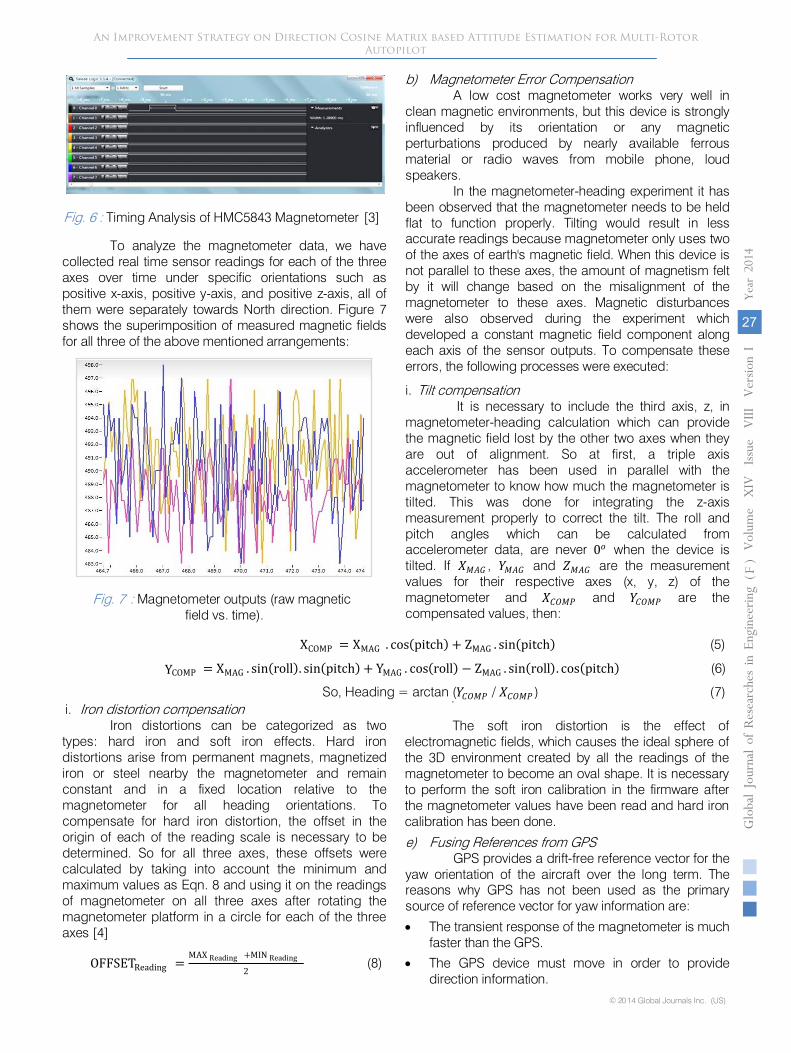
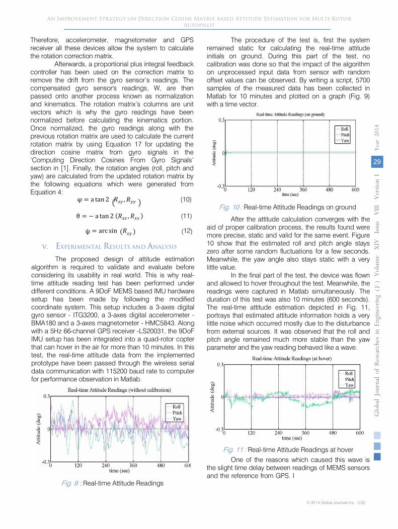
To analyze
the magnetometer data, we have collected
real time sensor readings for each of the three axes over time under specific orientations such as positive x-axis, positive y-axis,
and positive z-axis, all of them were separately towards North direction. Figure 7
shows the superimposition
of measured magnetic fields for
all three of the above mentioned arrangements:
Fig. 7 :
Magnetometer outputs (raw magnetic
field vs. time).
b) Magnetometer Error Compensation A low cost magnetometer works very well in
clean magnetic environments, but this device is strongly influenced by its orientation or any magnetic perturbations produced by nearly available ferrous material or radio waves from mobile phone, loud speakers.
In the magnetometer-heading experiment it has been observed that the magnetometer needs to be held flat to function properly. Tilting would result in less accurate readings because magnetometer only uses two of the axes of earth's magnetic field. When this device is not parallel to these axes, the amount of magnetism felt by it will change based on the misalignment of the magnetometer to these axes. Magnetic disturbances were also observed during the experiment which developed a constant magnetic field component along each axis of the sensor outputs. To compensate these errors, the following processes were executed:
i. Tilt compensation It is necessary to include the third axis, z, in
magnetometer-heading calculation which can provide the magnetic field lost by the other two axes when they are out of alignment. So at first, a triple axis accelerometer has been used in parallel with the magnetometer to know how much the magnetometer is tilted. This was done for integrating the z-axis measurement properly to correct the tilt. The roll and pitch angles which can be calculated from accelerometer data, are never 0𝑜𝑜 when the device is tilted. If 𝑋𝑋𝑀𝑀𝑀𝑀𝑀𝑀 , 𝑌𝑌𝑀𝑀𝑀𝑀𝑀𝑀 and 𝑍𝑍𝑀𝑀𝑀𝑀𝑀𝑀 are the measurement values for their respective axes (x, y, z) of the magnetometer and 𝑋𝑋𝐶𝐶𝐶𝐶𝑀𝑀𝐶𝐶 and 𝑌𝑌𝐶𝐶𝐶𝐶𝑀𝑀𝐶𝐶 are the compensated values, then:
XCOMP = XMAG . cos(pitch) + ZMAG . sin(pitch)
(5)
YCOMP = XMAG . sin(roll). sin(pitch) + YMAG . cos(roll) − ZMAG . sin(roll). cos(pitch)
(6)
So, Heading = arctan (𝑌𝑌𝐶𝐶𝐶𝐶𝑀𝑀𝐶𝐶
/ 𝑋𝑋𝐶𝐶𝐶𝐶𝑀𝑀𝐶𝐶 ) (7)i.
Iron distortion compensation
Iron distortions can be categorized as two types: hard iron and soft iron effects. Hard iron distortions arise from permanent magnets,
magnetized iron or steel nearby the magnetometer and remain constant and in a fixed location relative to the magnetometer
for all heading orientations. To compensate for hard iron distortion, the offset in the origin of each of the reading scale is necessary to be determined. So for all three axes, these offsets were
An Improvement Strategy on Direction Cosine Matrix based Attitude Estimation for Multi-Rotor Autopilot
Globa
l Jo
urna
l of
Resea
rche
s in E
nginee
ring
()
FVolum
e X
IV
Issu
e V
III V
ersion
I
27
Year
2014
© 2014 Global Journals Inc. (US)
Fig. 6 : Timing Analysis of HMC5843 Magnetometer [3]
calculated by taking into account the minimum and maximum values as Eqn. 8 and using it on the readings of magnetometer on all three axes after rotating the magnetometer platform in a circle for each of the three axes [4]
.
The soft iron distortion is the effect of electromagnetic fields, which causes the ideal sphere of the 3D environment created by all the readings of the magnetometer to become an oval shape. It is necessary to perform the soft iron calibration in the firmware after the magnetometer values have been read and hard iron calibration has been done.
OFFSETReading =MAX Reading +MIN Reading
2 (8)
e) Fusing References from GPSGPS provides a drift-free reference vector for the
yaw orientation of the aircraft over the long term. The reasons why GPS has not been used as the primary source of reference vector for yaw information are:
• The transient response of the magnetometer is much faster than the GPS.
• The GPS device must move in order to provide direction information.

•
The yaw reference cannot be updated under GPS denial environment.
In the attitude estimation process, magnetometer
has been used
for yaw reference vector and over a period of time the readings are jammed with offset values for various reasons. So when the GPS is available to calculate the heading information, the course over ground
is collected from GPS and used
to compensate the readings of magnetometer. While using the GPS signal, reporting latency and filtering have been taken into account.
The procedure
that has been followed to obtain
the course over ground information
using a low-cost GPS receiver
is:
•
First:
Three consecutive GPS positions had been measured.
•
Second:
Those position measurements had been compared to obtain two velocity measurements
•
Third:
The velocity measurements had been used to calculate the average velocity over a short period.
of multi-rotor aircrafts. The proposed attitude estimation algorithm calculates the orientation
of an aircraft, in respect to the rotation of the earth by using rotation matrices. Figure 8 is a visual representation of the proposed attitude estimation algorithm.
The input devices that were
used in the algorithm are:
•
Triple-axis gyro sensor: It measures angular velocity.
•
Triple-axis accelerometer: It measures earth’s gravitational
field minus acceleration.
•
Triple-axis magnetometer: It measures earth’s magnetic field.
•
GPS receiver: It measures drift free orientation and position information.
In this algorithm, the gyro sensor is the primary sensor used to calculate the orientation of a rigid body. Since gyro sensor’s readings have different offsets depending on which direction the gyro sensor is facing; when these readings are integrated
An Improvement Strategy on Direction Cosine Matrix based Attitude Estimation for Multi-Rotor Autopilot
Globa
l Jo
urna
l of
Resea
rche
s in E
nginee
ring
()
FVolum
e X
IV
Issu
e V
III V
ersion
I
28
Year
2014
© 2014 Global Journals Inc. (US)
Fig. 8 : Proposed attitude estimation algorithm for multi rotor aircrafts
• Finally: The course over ground had been calculated from average:
Heading = arctan (Yvelocity / Xvelocity ) (9)
f) Attitude Estimation Algorithm DesignAfter taking all these approaches into account, a
new development over the attitude estimation algorithm of [5] have been proposed for better flight performance
over time, it causes the integral result to drift. The accelerometer is not affected by drift; therefore, it has been used as an orientation reference of that rigid body to compensate the roll-pitch error (i.e. gyro’s offset error). After error compensation, the magnetometer’s readings has been used to calculate the heading (i.e. yaw movement) of that rigid body. To refresh the measured yaw information with true values over long time period, the GPS signal has also been used when the signal is available and ready to generate valid yaw information.
An Improvement Strategy on Direction Cosine Matrix based Attitude Estimation for Multi-Rotor Autopilot
Globa
l Jo
urna
l of
Resea
rche
s in E
nginee
ring
()
FVolum
e X
IV
Issu
e V
III V
ersion
I
29
Year
2014
© 2014 Global Journals Inc. (US)
The procedure of the test is, first the system remained static for calculating the real-time attitude initials on ground. During this part of the test, no calibration was done so that the impact of the algorithmon unprocessed input data from sensor with random offset values can be observed. By writing a script, 5700 samples of the measured data has been collected in Matlab for 10 minutes and plotted on a graph (Fig. 9) with a time vector.
Fig. 10 : Real-time Attitude Readings on ground
After the attitude calculation converges with the aid of proper calibration process, the results found weremore precise, static and valid for the same event. Figure 10 show that the estimated roll and pitch angle stays zero after some random fluctuations for a few seconds. Meanwhile, the yaw angle also stays static with a very little value.
In the final part of the test, the device was flown and allowed to hover throughout the test. Meanwhile, the readings were captured in Matlab simultaneously. The duration of this test was also 10 minutes (600 seconds). The real-time attitude estimation depicted in Fig. 11, portrays that estimated attitude information holds a very little noise which occurred mostly due to the disturbance from external sources. It was observed that the roll and pitch angle remained much more stable than the yaw parameter and the yaw reading behaved like a wave.
Therefore, accelerometer, magnetometer and GPS receiver all these devices allow the system to calculate the rotation correction matrix.
Afterwards, a proportional plus integral feedback controller has been used on the correction matrix to remove the drift from the gyro sensor’s readings. The compensated gyro sensor's readings, W, are then passed onto another process known as normalization and kinematics. The rotation matrix’s columns are unit vectors which is why the gyro readings have been normalized before calculating the kinematics portion. Once normalized, the gyro readings along with the previous rotation matrix are used to calculate the current rotation matrix by using Equation 17 for updating the direction cosine matrix from gyro signals in the ‘Computing Direction Cosines From Gyro Signals’ section in [1]. Finally, the rotation angles (roll, pitch and yaw) are calculated from the updated rotation matrix by the following equations which were generated from Equation 4:
φ = a tan 2 �𝑅𝑅𝑧𝑧𝑦𝑦 ,𝑅𝑅𝑦𝑦𝑦𝑦 � (10)
θ = − a tan 2 (𝑅𝑅𝑥𝑥𝑧𝑧 ,𝑅𝑅𝑥𝑥𝑥𝑥 ) (11)
ψ = arc sin (𝑅𝑅𝑥𝑥𝑦𝑦 ) (12)
v. EXPERIMENTAL RESULTS AND ANALYSIS
The proposed design of attitude estimation algorithm is required to validate and evaluate before considering its usability in real world. This is why real-time attitude reading test has been performed under different conditions. A 9DoF MEMS based IMU hardware setup has been made by following the modified coordinate system. This setup includes a 3-axes digital gyro sensor - ITG3200, a 3-axes digital accelerometer - BMA180 and a 3-axes magnetometer - HMC5843. Along with a 5Hz 66-channel GPS receiver -LS20031, the 9DoFIMU setup has been integrated into a quad-rotor copter that can hover in the air for more than 10 minutes. In this test, the real-time attitude data from the implemented prototype have been passed through the wireless serial data communication with 115200 baud rate to computer for performance observation in Matlab.
Fig. 9 : Real-time Attitude Readings
Fig. 11 : Real-time Attitude Readings at hover
One of the reasons which caused this wave is the slight time delay between readings of MEMS sensors and the reference from GPS. I
:

rotation rate errors consist
of the constant bias and the random noise. During the test, GPS observation is available every 200ms.
Therefore the attitude data
derived from MEMS
sensors
updated by GPS
are at a rate of 5Hz.
From these test
results, it can be concluded that the proposed algorithm can impressively
deal
with the MEMS gyro drifts with better consistency. So, this test validates the proposed design algorithm and strategy.
vi.
CONCLUSIONS
This paper presented an improved attitude estimation method based on the Direction Cosine Matrix. This estimator is built for attitude control and stabilization of multi-rotor autopilot systems. The unresolved issues
that still exist can be corrected and considered for future improvements. Future applications will be presented
with
the integration of position, attitude and altitude estimation based on GPS/IMU/computer vision/
ultrasonic sound, resulting in an estimator of twelve
degrees of freedom that will be used for tracking and navigation.
References Références
Referencias
1.
D. Choukroun, H. Weiss, I. Y. Bar-Itzhack, and Y. Oshman, "Direction cosine matrix estimation from
An Improvement Strategy on Direction Cosine Matrix based Attitude Estimation for Multi-Rotor Autopilot
Globa
l Jo
urna
l of
Resea
rche
s in E
nginee
ring
()
FVolum
e X
IV
Issu
e V
III V
ersion
I
30
Year
2014
© 2014 Global Journals Inc. (US)
report, Texas Instruments Inc., Texas, February 2012, pp. 3–7.
vector observations using a matrix Kalman filter", IEEE Trans. Aerosp. Electron. Syst., vol. 46, no. 1, 2010, pp. 1.
2. W. Premerlani and P. Bizard, "Direction Cosine Matrix IMU: Theory", Tech. Rep., May 2009. pp. 8-20.
3. AQ. flight software timing, Carancho Engineering, November 2010, unpublished.
4. Konvalin, "Compensating for Tilt, Hard-Iron, and Soft-Iron Effects", 2009.
5. (http://www.sensorsmag.com/sensors/motion-velo-city-displacement/compensating-tilt-hard-iron-and-soft-iron-effects-6475)
-6. E.Macias, D. Torres, and S. Ravindran, "Nine axis sensor fusion using the Direction Cosine Matrix Algorithm on the MSP430F5xx Family", Application
vii. ACKNOWLEDGMENT
The authors would like to convey very special thanks to Prof. Dr. Tafazzal Hossain, Vice President (Academics) and Prof. Dr. A. B. M. Siddique Hossain, Dean (Faculty of Engineering), American International University-Bangladesh, for their valuable advice and encouragement. The authors would also like to acknowledge their undergraduate project and thesis supervisor, Rezwan Ahmed, Assistant Professor, Department of Computer Science, American International University-Bangladesh, for his support and helpful suggestions regarding the subject matter.