an improved air-driven type of ultracen-
TRANSCRIPT

AN I M P R O V E D A I R - D R I V E N T Y P E OF U L T R A C E N - T R I F U G E FOR M O L E C U L A R S E D I M E N T A T I O N
B~ JOHANNES H. BAUER, M.D., AND EDWARD G. PICKELS, I~.D.
(From the Laboratories of the International Health Division, The Rockefeller Foundation, New York)
(Received for publication, February 3, 1937)
INTRODUCTION
In 1925 Henriot and Huguenard (i) described a new method for obtaining high rotational speeds without the use of mechanical bearings. Employing a whirling layer of air issuing under pressure from properly directed jets for both supporting and driving a small cone-shaped rotor measuring 11.7 ram. in diameter, they reported attaining speeds up to 660,000 revolutions per minute. In another paper (2), 2 years later the same authors described their attempts to adapt the air- drive principle for several practical purposes. These included a Sharples type of centrifuge with a cylinder weighing 2,500 gin., which they reported to have suc- cessfuUy spun at a speed of 65,000 mP.g. They also claimed to have attained speeds up to 360,000 R.p.~s. with a rotor carrying a small mirror. The new method for obtaining high rotational speeds without the use of mechanical bearings was soon confirmed by Beams (3). In order to eliminate some of the rather objection- able vibration, Beams introduced certain modifications into the design of Henriot and Hugnenard and obtained rotational speeds up to 180,000 R.p.x~. with a rotor measuring about 30 ram. in diameter and carrying a small stellite mirror. He was also successful in photographing dectric sparks as reflected from the rapidly rotating mirror (4). Substituting compressed hydrogen in place of air for driving purposes, and using a plain rotor only 9 ram. in diameter, Beams, Pickels, and Weed (5) reported attaining rotational speeds of over 1,200,000 R.p.x,.
The possibility that this method of obtaining high rotational speeds might be utilized with advantage in designing and constructing high speed centrifuges suitable for chemical and biological investigations naturally suggested itself, and subsequently there have appeared several reports of such attempted applications. The rapidly spinning rotor has been employed as a centrifuge in studying the effects of high centrifugal forces upon certain cells by Harvey (6, 7), by Beams and King (8, 9), and by Guyer and Claus (10). McIntosh (11) reported using it for the centrifugation of bacteriophage and fowl sarcoma virus. Beams, Weed, and Pickels (12, 5) have described arrangements designed for the separation of protein molecules and other small particles in solution. McBain and O'SuRivan (13, 14)
565
Dow
nloaded from http://rupress.org/jem
/article-pdf/65/4/565/1140793/565.pdf by guest on 07 January 2022
566 IMPROVED MOLECULAR ULTRACENTKIFUGE
have given detailed descriptions of an apparatus involving the use of a small air- driven rotor for the determination of the sedimentation constants of protein molecules in solution. These authors claimed to have been successful in recording photographically the sedimentation boundaries of certain large monodisperse proteins.
A considerable amount of research has been carried out by the writers in an effort to utilize the air-drive principle of Henriot and Huguenard in the design and construction of a high speed centrifuge suitable for the study of filterable viruses. For this purpose, two types of centrifuges seemed essential: one, for the concen- tration and purification of viruses, and therefore capable of accommodating a relatively large amount of fluid; the other, with a suitable optical system, for the study of the physical characteristics of the viruses by determining their sedimen- tation constants in an intense centrifugal field. In the course of these investiga- tions, it soon became evident that high rotational speeds were obtainable by this method only with relatively small rotors, the dimensions of which were wholly unsuitable for our purpose. A number of models were built, and rotors varying from 50 to 200 ram. in diameter were tried, With the increase of the rotor diam- eter and the resulting increase in the surface area of the rotor exposed to air friction, there was a corresponding decrease in the maximum speed obtainable. A speed of 16,000 R.1,.~. could not be exceeded with a rotor measuring 200 mm. in diameter, regardless of the large volume of the compressed air under high pressure employed for driving purposes (Bauer and Pickels (15)). Moreover, we were not able to devise a satisfactory arrangement to prevent the development of tem- perature gradients and the resulting convection currents which interfere with normal sedimentation. These limitations, coupled with certain other difficulties encountered in these investigations, led us to abandon the hope of adapting the simple air turbine of Henriot and Hugnenard as a high speed centrifuge suitable for the studies in which we were especially interested.
Pickels and Beams (16) were the first to describe a new type of air turbine drive with which it was possible to obtain high rotational speeds with larger rotors without exposing them to appreciable air friction. To a friction clutch, inserted into a small cone-shaped air-driven rotor of the Henriot and Hugnenard type, they attached a length of straightened piano wire which was extended downward through an oil gland into a vacuum chamber and there fastened to a larger rotor. This wire served as a drive shaft. At the lower end of the rotor a stabilizing device was used. When a high degree of vacuum was maintained in the chamber housing the larger rotor, only a relatively small amount of driving energy was necessary to attain rotational speeds which were limited only by the strength of the material used for the rotor. Later this driving mechanism was somewhat modified by Beams and Pickels (17), in that the friction clutch and the stabilizer were elim- inated, a certain degree of flexibility was given to the mounting of the oil gland, and two separate air systems were used, one for supporting and the other for driving the turbine. Utilizing the principles described by Pickels and Beams (16), Biscoe, Pickeh, and Wyckoff (18) constructed a centrifuge in which they used a
Dow
nloaded from http://rupress.org/jem
/article-pdf/65/4/565/1140793/565.pdf by guest on 07 January 2022
JOHANNES H. BAUER AND EDWARD G. PICKELS 567
friction clutch in the turbine as well as two air systems for supporting and driving purposes. Large circular duralumin rotors measuring about 176 ram. in diameter and carrying transparent ceils similar to those designed by Svedberg and his coworkers (19) were used. They also adapted the optical systems of Svedberg and were able to record photographically the sedimentation of protein molecules in their centrifuge.
Recently Bauer and Pickels (20) described a high speed vacuum centrifuge designed for the concentration and purification of filter- able viruses. An air turbine drive, which was a further modifica- tion of those described by the investigators referred to above, proved to be highly efficient for this centrifuge. The turbine and its load were supported by a new type of air-bearing arrangement in which was employed for the first time a special floating unit designed to absorb more efficiently vibrations generated in the turbine and to give it an increased stability at all speeds. This bearing unit was made to function entirely independently of the driving system. The new type of driving mechanism was provided with a set of reversed air jets by which the rotor could be rapidly decelerated and within a short time brought to rest from high speed. With this type of air bearing, only a comparatively small amount of compressed air was required to spin large and heavy rotors at speeds which were limited solely by the strength of the material from which the rotors were made. The application of this driving mechanism to a molecular centrifuge for the determination of the sedimentation constants of proteins has now proved equally successful. The rotation of an oval- shaped rotor at very high speed has been steady and vibrationless, and there has been no evidence of convection currents interfering with the sedimentation of the protein molecules. Following is a detailed description of this centrifuge assembly, including the adapta- tion of Svedberg's optical system.
The Improved Centrifuge
Driving Mechanism.--The driving mechanism has already been fully described in a recent report (20), and in the present paper only certain features are briefly mentioned in connection with its adaptation to the molecular ultracentrifuge. The one major change introduced is a reduction of the diameter of the driving turbine to 35 ram. in order to minimize air friction, inasmuch as the rotors of the molecular ultracentrifuge are lighter than those described in the previous report
Dow
nloaded from http://rupress.org/jem
/article-pdf/65/4/565/1140793/565.pdf by guest on 07 January 2022
568 IMPROVED MOLECULAR ULTRACENTRIFUGE
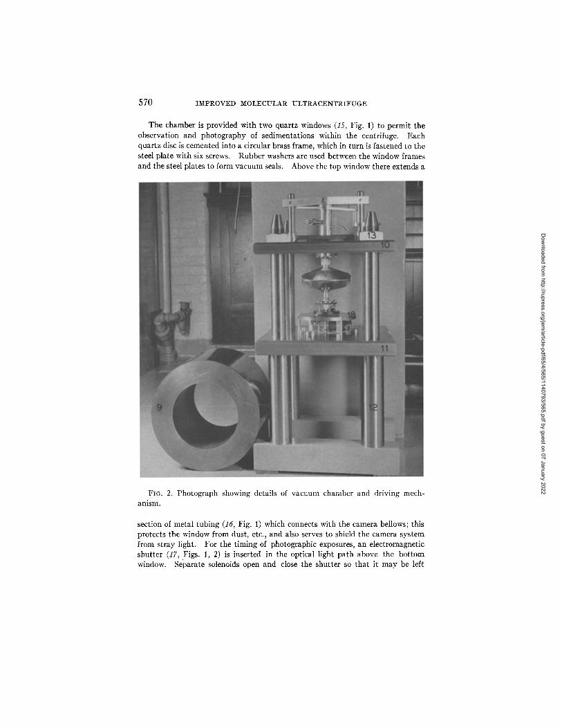
and are run at higher speeds. In Figs. 1 and 2 are shown the arrangement used in the mounting of the mechanism on the vacuum chamber and the details of the system used for collecting the lubricating oil entering the chamber. In order to provide the necessary degree of flexibility and dampening, the whole driving mechanism is mounted on a fairly heavy metal plate (1, Fig. 1) which rests on four small rubber cushions (2, Fig. 1). The vacuum seal between the chamber and the driving mechanism is effected by means of soft, thick walled rubber tubing (3, Fig. 1) which connects the lower stem of the oil gland (4, Fig. 1) to a sleeve (5, Fig. 1) fastened to the top plate of the vacuum chamber. Lubricating oil of a low vapor tension, forced under continuous pressure into the central cavity of the oil gland (6, Fig. 1), lubricates the bearings and also serves to form a vacuum seal about the drive shaft. Oil escaping from the upper bearing is drained into a container located above the chamber. For collecting oil that escapes from the lower bearing into the vacuum chamber, a duralumin disc with a diameter slightly larger than the aperture in the circular oil collector which surrounds it (7, Fig. 1), is fitted tightly on the drive shaft beneath the lower bearing. Oil thrown from the disc into the collector is drained through a copper tubing into a cup fastened to the top of the chamber (8, Fig. 1). The oil collected in the chamber during a run has averaged about 1 cc. per hour, and consequently its removal is required only at infrequent intervals.
Vacuum Chamber.--The vacuum chamber in which the centrifuge rotates consists of a cylinder and two end plates as shown in Figs. 1 and 2. The cylinder (9, Figs. 1, 2) is of chrome nickel steel alloy, S.A.E. 3140, and its dimensions are: height 28 cm., inside diameter 22.8 cm., and wall thickness 7.6 cm. After casting, it is machined to the desired shape and heat-treated to glve a maximum tensile strength to the steel. After the heat treatment the ends are ground smooth and parallel to facilitate securing satisfactory vacuum seals when joined with the end plates. The end plates are made of hot rolled steel; they measure 52.5 cm. square and are machined smooth and fiat. Through the plates at each corner there is drilled a 5 cm. hole. The thickness of the top plate (10, Figs. 1, 2) is 3.8 cm., and that of the bottom plate (11, Figs. 1, 2) is 5 cm. The chamber rests on four steel legs (12, Fig. 2) which are also fashioned into the form of bolts. The diameter of each leg is 7.5 cm. to a height of 30.5 cm., and from there on is reduced to 5 cm. The upper ends are threaded and provided with heavy steel nuts (13, Figs. 1, 2). Passing through the holes in the corners of the bottom plate and thus bringing the latter to rest on the shoulders, the bolts extend along the outer wall of the cylinder and then pass through the holes at the corners of the top plate with a slight clear- ance. This arrangement provides for an automatic alignment of the optical light path when the chamber is closed, and also permits the end plates to be securely bolted together when the chamber is closed during a run. Thin rubber washers (14, Fig. 1) and lubriseal are used to effect a vacuum-tight seal between the cyl- inder and the end plates. Into the edge of the bottom plate there are drilled two holes which have openings into the chamber itself. One of these leads to the vacuum pump, and the other to the vacuum gauge. In addition there are drilled
Dow
nloaded from http://rupress.org/jem
/article-pdf/65/4/565/1140793/565.pdf by guest on 07 January 2022

JOHANNES H. B A U E R AND EDWARD G. PICKELS
~=~
569
',a.iP~"
5 5 - -
FIG. 1. Vertical cross-section view of vacuum chamber and driving mechanism.
through the thickness of the bottom plate several smaller holes which are tightly closed with rubber stoppers. Wires passing through these stoppers serve as electrical leads for an electromagnetic shutter and for the temperature-measuring devices.
Dow
nloaded from http://rupress.org/jem
/article-pdf/65/4/565/1140793/565.pdf by guest on 07 January 2022
570 IMPROVED MOLECULAR ULTRACENTRIFUGE
The chamber is provided with two quartz windows (15, Fig. 1) to permit the observation and photography of sedimentations within the centrifuge. Each quartz disc is cemented into a circular brass frame, which in turn is fastened to the steel plate with six screws. Rubber washers are used between the window frames and the steel plates to form vacuum seals. Above the top window there extends a
FIG. 2. Photograph showing details of vacuum chamber and driving mech- anism.
section of metal tubing (16, Fig. 1) which connects with the camera bellows; this protects the window from dust, etc., and also serves to shield the camera system from stray light. For the timing of photographic exposures, an electromagnetic shutter (17, Figs. 1, 2) is inserted in the optical light path above the bottom window. Separate solenoids open and close the shutter so that it may be left
Dow
nloaded from http://rupress.org/jem
/article-pdf/65/4/565/1140793/565.pdf by guest on 07 January 2022

JOHANNES H. BAUER AND EDWARD G. PICKELS 571
either in an opened or a closed position for any length of time without maintaining a continuous supply of electrical energy which might result in an undesirable amount of heating in the chamber. The shutter has the additional purpose, especially during the opening and closing of the vacuum chamber, of protecting the bottom window from dust, oil droplets, etc.
The bottom of the vacuum chamber is provided with an elevated flooring (18, Figs. 1, 2) which is made of brass sheeting 13 mm. thick and mounted on three legs above the shutter. The purpose of this arrangement is twofold: it serves as a protection to the shutter, the bottom window, and the electrical wiring system in the unexpected event of the rotor's dropping from the drive shaft; and it also furnishes a convenient support for the temperature-measuring device described below.
Rotor.--The work of Svedberg and his associates as well as our own experience has clearly demonstrated that ultracentrifuge rotors with transparent cells can be made to withstand considerably greater centrifugal force if they are made oval rather than circular in shape. The two holes cut into the rotor opposite each other to accommodate the transparent cell and its counterbalance result in an asym- metrical distribution of stresses during rotation. The danger of rupture is much diminished and the maximum speed obtainable materially increased if the excess of metal is removed from the solid sections along the periphery farthest from the holes. Strength is also added to the rotor if its thickness is progres- sively increased from the periphery toward the center as much as the design permits.
Among the various metals suitable for rotors, an aluminum alloy known as 14 ST has proved most satisfactory for our purposes (21). I t has the chief ad- vantage over special steel alloys in that the stock supplied by the manufacturers, although already heat-treated to bring out its maximum tensile strength, is rela- tively soft and very easily machined, and the rotor can be finished completely without subjecting it to the additional heat treatment and subsequent grinding process that are necessary with steel alloys. I t is also sufficiently malleable to allow a slight flow under tension, a property which minimizes the danger of gen- erating localized stresses and strains that are apt to initiate a rupture at high speed. Moreover, having only about one-third the density of steel and being very much softer than a heat-treated steel alloy, a duralumin rotor exploding at excessive speed is not nearly so dangerous as a steel one. According to the stress-strain data 1 available, the 14 ST alloy has an ultimate tensile strength of 67,400 pounds per square inch, yield strength of 57,000 pounds per square inch, elongation 15.8 per cent, reduction of area 31.1 per cent, Brinell hardness 131.5, and modulus of elasticity 10,400,000 lb. per sq. in. The specific tensile strength of this alloy corn-
1 We are indebted for these data to Mr. R. L. Templin, Chief Engineer of Tests, Aluminum Research Laboratories of the Aluminum Company of America, New Kensington, Pennsylvania.
Dow
nloaded from http://rupress.org/jem
/article-pdf/65/4/565/1140793/565.pdf by guest on 07 January 2022
572 IMPROVED MOLECULAR ULTRACENTRIFUGE
pares favorably with that of a steel alloy having a tensile strength of 200,000 lb. per sq. in., viz.
steel: tensile strength 200,000 67,400
density 7.8 - 25,604; 14 ST: 2.8 - 24,070
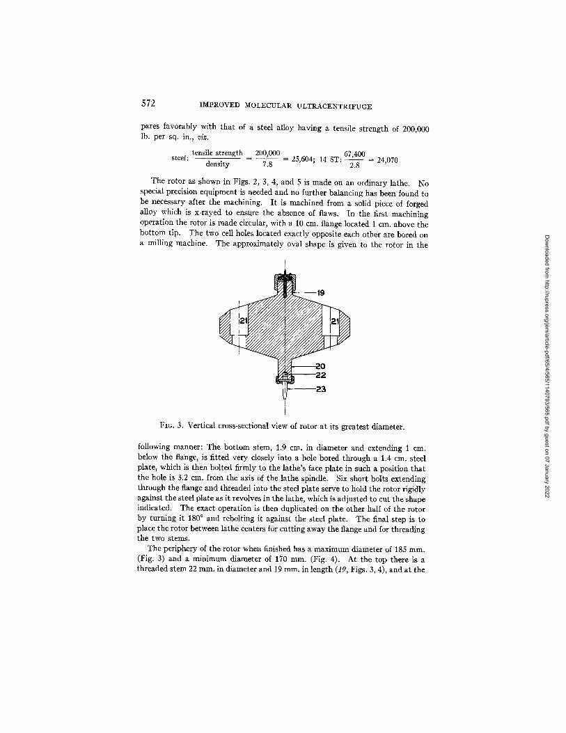
The rotor as shown in Figs. 2, 3, 4, and 5 is made on an ordinary lathe. No special precision equipment is needed and no further balancing has been found to be necessary after the machining. I t is machined from a solid piece of forged alloy which is x-rayed to ensure the absence of flaws. In the first machining operation the rotor is made circular, with a 10 cm. flange located 1 cm. above the bottom tip. The two cell holes located exactly opposite each other are bored on a milling machine. The approximately oval shape is given to the rotor in the
2 2
FIG. 3. Vertical cross-sectional view of rotor at its greatest diameter.
following manner: The bottom stem, 1.9 cm. in diameter and extending 1 cm. below the flange, is fitted very closely into a hole bored through a 1.4 cm. steel plate, which is then bolted firmly to the lathe's face plate in such a position that the hole is 3.2 cm. from the axis of the lathe spindle. Six short bolts extending through the flange and threaded into the steel plate serve to hold the rotor rigidly against the steel plate as it revolves in the lathe, which is adjusted to cut the shape indicated. The exact operation is then duplicated on the other half of the rotor by turning it 180 ° and rebolting it against the steel plate. The final step is to place the rotor between lathe centers for cutting away the flange and for threading the two stems.
The periphery of the rotor when finished has a maximum diameter of 185 ram. (Fig. 3) and a minimum diameter of 170 ram. (Fig. 4). At the top there is a threaded stem 22 mm. in diameter and 19 ram. in length (19, Figs. 3, 4), and at the
Dow
nloaded from http://rupress.org/jem
/article-pdf/65/4/565/1140793/565.pdf by guest on 07 January 2022
JOHANNES H. BAUER AND EDWARD G. PICKELS 573
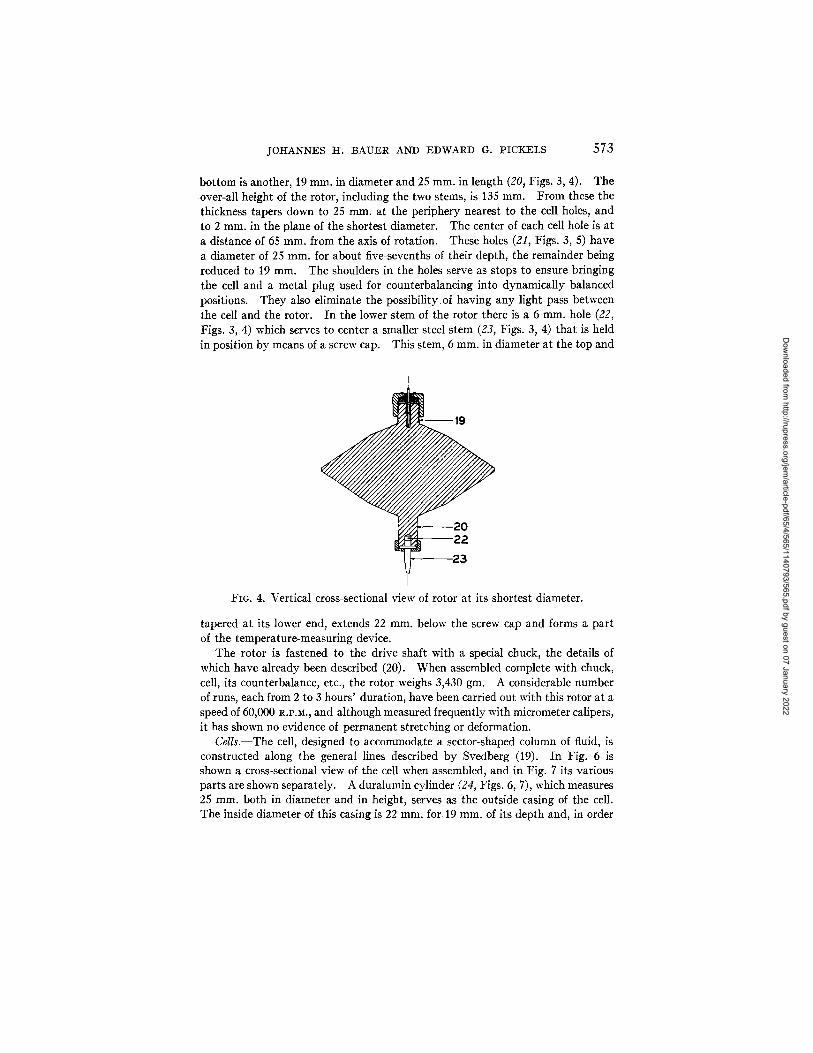
bottom is another, 19 mm. in diameter and 25 mm. in length (20, Figs. 3, 4). The over-all height of the rotor, including the two stems, is 135 mm. From these the thickness tapers down to 25 ram. at the periphery nearest to the cell holes, and to 2 mm. in the plane of the shortest diameter. The center of each cell hole is at a distance of 65 mm. from the axis of rotation. These holes (21, Figs. 3, 5) have a diameter of 25 mm. for about five-sevenths of their depth, the remainder being reduced to 19 mm. The shoulders in the holes serve as stops to ensure bringing the cell and a metal plug used for counterbalancing into dynamically balanced positions. They also eliminate the possibility of having any light pass between the cell and the rotor. In the lower stem of the rotor there is a 6 mm. hole (22, Figs. 3, 4) which serves to center a smaller steel stem (23, Figs. 3, 4) that is held in position by means of a screw cap. This stem, 6 mm. in diameter at the top and
i
19
20 22
FIG. 4. Vertical cross-sectional view of rotor at its shortest diameter.
tapered at its lower end, extends 22 mm. below the screw cap and forms a part of the temperature-measuring device.
The rotor is fastened to the drive shaft with a special chuck, the details of which have already been described (20). When assembled complete with chuck, cell, its counterbalance, etc., the rotor weighs 3,430 gm. A considerable number of runs, each from 2 to 3 hours' duration, have been carried out with this rotor at a speed of 60,000 R.P.M., and although measured frequently with micrometer calipers, it has shown no evidence of permanent stretching or deformation.
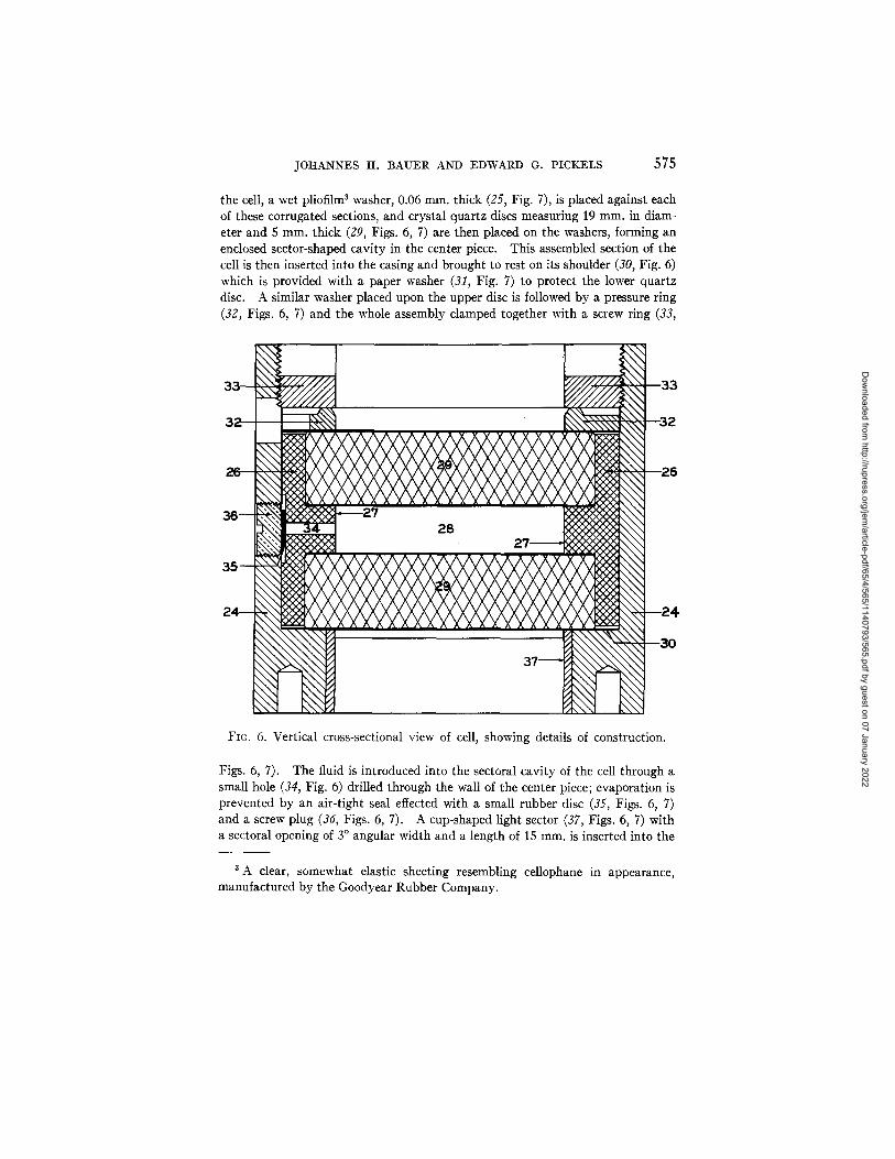
Cells.--The cell, designed to accommodate a sector-shaped column of fluid, is constructed along the general lines described by Svedberg (19). In Fig. 6 is shown a cross-sectional view of the cell when assembled, and in Fig. 7 its various parts are shown separately. A duralumin cylinder (24, Figs. 6, 7), which measures 25 mm. both in diameter and in height, serves as the outside casing of the cell. The inside diameter of this casing is 22 ram. for- 19 ram. of its depth and, in order
Dow
nloaded from http://rupress.org/jem
/article-pdf/65/4/565/1140793/565.pdf by guest on 07 January 2022
574 IMPROVED MOLECULAR ULTRACENTRIFUGE
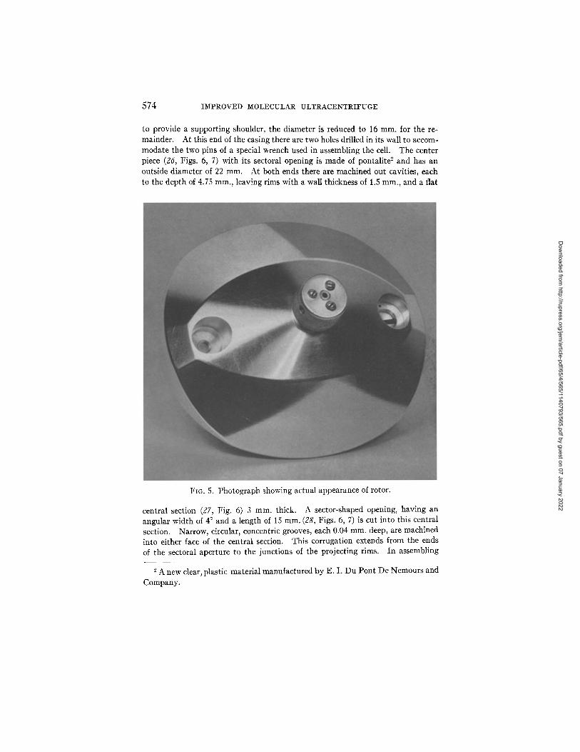
to provide a supporting shoulder, the diameter is reduced to 16 ram. for the re- mainder. At this end of the casing there are two holes drilled in its wall to accom- modate the two pins of a special wrench used in assembling the cell. The center piece (26, Figs. 6, 7) with its sectoral opening is made of pontalite ~ and has an outside diameter of 22 ram. At both ends there are machined out cavities, each to the depth of 4.75 ram., leaving rims with a wall thickness of 1.5 ram., and a flat
FIG. 5. Photograph showing actual appearance of rotor.
central section (27, Fig. 6) 3 mm. thick. A sector-shaped opening, having an angular width of 4 ° and a length of 15 ram. (28, Figs. 6, 7) is cut into this central section. Narrow, circular, concentric grooves, each 0.04 mm, deep, are machined into either face of the central section. This corrugation extends from the ends of the sectoral aperture to the junctions of the projecting rims. In assembling
2 A new clear, plastic material manufactured by E. I. Du Pont De Nemours and Company.
Dow
nloaded from http://rupress.org/jem
/article-pdf/65/4/565/1140793/565.pdf by guest on 07 January 2022
JOHANNES H. BAUER AND EDWARD G. PICKELS 575
the cell, a wet pliofilm 3 washer, 0.06 mm. thick (25, Fig. 7), is placed against each of these corrugated sections, and crystal quartz discs measuring 19 mm. in diam- eter and 5 ram. thick (29, Figs. 6, 7) are then placed on the washers, forming an enclosed sector-shaped cavity in the center piece. This assembled section of the cell is then inserted into the casing and brought to rest on its shoulder (30, Fig. 6) which is provided with a paper washer (31, Fig. 7) to protect the lower quartz disc. A similar washer placed upon the upper disc is followed by a pressure ring (32, Figs. 6, 7) and the whole assembly clamped together with a screw ring (33,
FIG. 6. Vertical cross-sectional view of cell, showing details of construction.
Figs. 6, 7). The fluid is introduced into the sectoral cavity of the cell through a small hole (34, Fig. 6) drilled through the wall of the center piece; evaporation is prevented by an air-tight seal effected with a small rubber disc (35, Figs. 6, 7) and a screw plug (36, Figs. 6, 7). A cup-shaped light sector (37, Figs. 6, 7) with a sectoral opening of 3 ° angular width and a length of 15 ram. is inserted into the
A clear, somewhat elastic sheeting resembling cellophane in appearance, manufactured by the Goodyear Rubber Company.
Dow
nloaded from http://rupress.org/jem
/article-pdf/65/4/565/1140793/565.pdf by guest on 07 January 2022
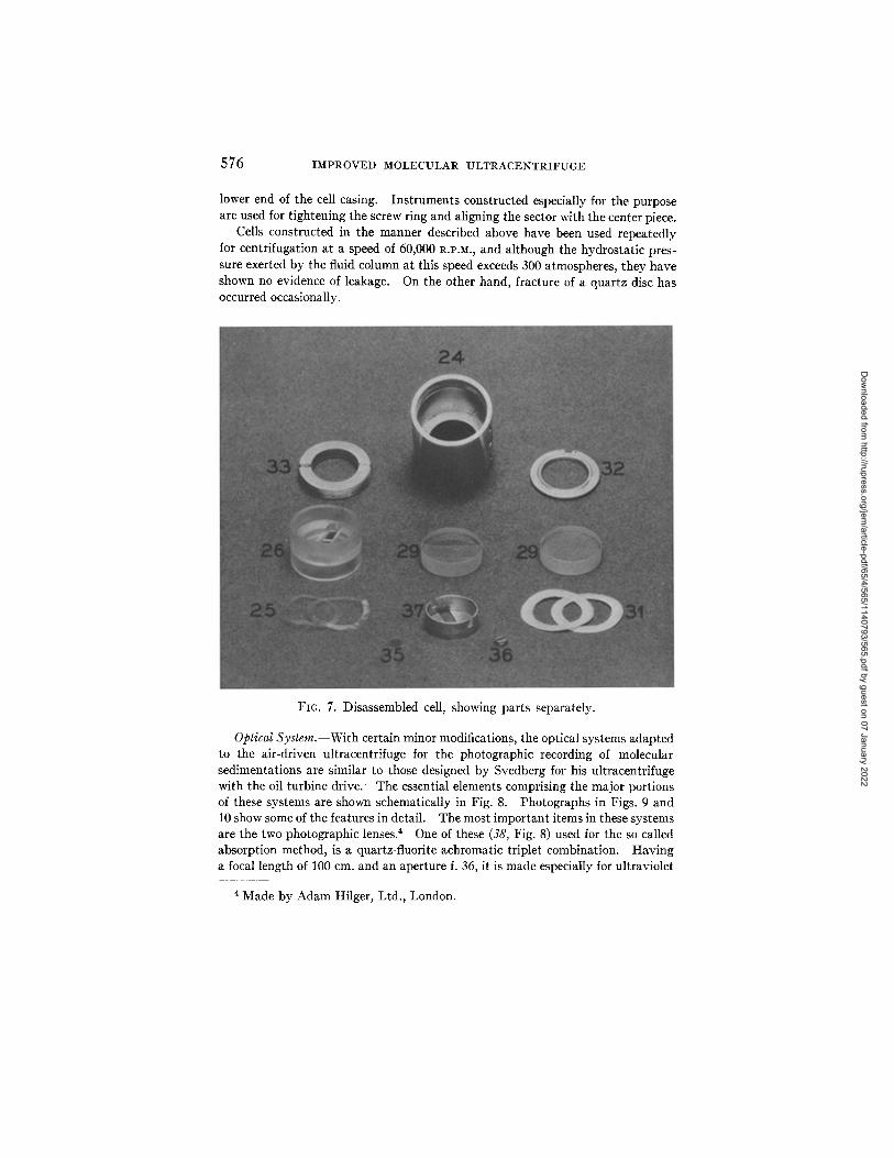
576 IMPROVED MOLECULAR ULTRACENTRIFUGE
lower end of the cell casing. Instruments constructed especially for the purpose are used for tightening the screw ring and aligning the sector with the center piece.
Cells constructed in the manner described above have been used repeatedly for centrifugation at a speed of 60,000 I~.P.M., and although the hydrostatic pres- sure exerted by the fluid column at this speed exceeds 300 atmospheres, they have shown no evidence of leakage. On the other hand, fracture of a quartz disc has occurred occasionally.
FIG. 7. Disassembled cell, showing parts separately.
Optical System.--With certain minor modifications, the optical systems adapted to the air-driven ultracentrifuge for the photographic recording of molecular sedimentations are similar to those designed by Svedberg for his ultracentrifuge with the oil turbine drive. The essential elements comprising the major portions of these systems are shown schematically in Fig. 8. Photographs in Figs. 9 and 10 show some of the features in detail. The most important items in these systems are the two photographic lenses. 4 One of these (38, Fig. 8) used for the so called absorption method, is a quartz-fluorite achromatic triplet combination. Having a focal length of 100 cm. and an aperture f. 36, it is made especially for ultraviolet
4 Made by Adam Hilger, Ltd., London.
Dow
nloaded from http://rupress.org/jem
/article-pdf/65/4/565/1140793/565.pdf by guest on 07 January 2022

JOIi.ANNES H. BAUER AND EDWARD G. PICKELS 577
photography. The other (39, Fig. 8), employed for the refractive index method, is a quartz-glass triplet corrected for 3,500 to 4,500 .~ and having a focal length of 150 cm.
As seen from the photographs in Figs. 9 and 10, the entire centrifuge assembly occupies two rooms. Heavy seamless steel pipes (40, 41, Figs. 9, 10), which extend through the wall between the rooms, form the main body of the cameras. In the room which houses the centrifuge (Fig. 9) the ends of these camera tubes are mounted one above the other in a heavy steel support, which in turn is bolted to a large channel-shaped concrete block. In the other room each tube is mounted on a separate hollow steel column; these columns are filled with concrete and their lower ends are embedded in square concrete blocks. In order to obviate the transmission of troublesome vibration from the building to the camera systems,
i.t%,
FIG. 8. Schematic view of light path and optical system.
all three blocks as well as the centrifuge chamber itself are mounted on soft rub- ber pads.
Inside each steel camera tube there is a smooth fitting brass tube having a length of 300 cm. Each of these inner tubes has its camera lens fitted at one end and a photographic plate holder (42, 43, Figs. 8, 10) at the other end. Correct adjustment for the necessary focusing is permitted by the telescopic action of this double tube arrangement.
Through the lower middle section of the concrete block adjacent to the centri- fuge is an opening 61 cm. wide and 38 cm. high. Into this extends the optical bench (44, Fig. 9) on which can be mounted either a projection system for index of refraction measurements or an illuminating system for absorption studies. The latter system, arranged for work in the middle ultraviolet, is illustrated in the drawing (Fig. 8). The light which eventually forms the photographic image is furnished by a 220 volt mercury arc lamp (45, Figs. 8, 9). It passes successively through the water filter (46, Fig. 8), the chlorine, and the bromine gas filters
Dow
nloaded from http://rupress.org/jem
/article-pdf/65/4/565/1140793/565.pdf by guest on 07 January 2022

57s IMPROVED MOLECULAR ULTRACENTRIFUGE
(47, Fig. 8). The approximately monochromatic ultraviolet light transmitted is then directed with a crystal quartz prism (48, Fig. 8) through the centrifuge into the camera head, and from there by means of a sputtered a luminum mirror (49, Fig. 8) to the camera lens. The sputtered mirror is mounted at 45 ° on a base which is held by springs against the pointed tips of three screws. Movement to two of these screws can be transmitted from either of two sets of adjusting wheels located near the photographic plate holders. The motion is transferred through the long steel rods (50, Figs. 9, 10) and the rubber belting (51, Fig. 9) to the two pulley wheels (52, Fig. 9) connected to the screws. The arrangement affords a simple means for slightly tilting the mirror in any direction and centering the photographic image at the plate holder. The camera head, which connects with the centrifuge chamber through a flexible cloth bellows (53, Figs. 8, 9), is made interchangeable in order that it may be fitted to the upper camera tube when index of refraction studies are being made.
Vacuum System.--Since the amount of frictional heat developed in the rotor is dependent on the degree of vacuum obtained in the centrifuge chamber, it is important that the vacuum system have a maximum of efficiency. A Cenco megavac pump is used to maintain a high degree of vacuum in the chamber during a run, and a McLeod gauge is used to measure the pressures. In the vacuum line leading to the gauge there is a three-way valve made of glass and fitted with mercury seals. One setting of the valve connects the gauge with the centrifuge chamber, and another setting opens the system to the atmosphere and allows the chamber to be filled with air. Metal tubing is used for the vacuum lines as far as possible, and rubber tubing is used only for connections which must be flexible.
Temperature Measurements.--For a quanti tat ive determination of molecular sedimentation in a centrifugal field, it is essential that the temperature of the material be known at all times during centrifugation. I t is also desirable to keep a record of temperature fluctuations in other parts of the centrifuge. For such temperature measurements, copper-constantan thermocouple junctions are con- nected to the oil bearings, to the chamber wall, and to a small cup of mercury into which projects the lower steel stem of the rotor. This cup shown in Figs. 1 and 2, is part of a simple device which has been found capable of registering the tempera- ture of a rotor at high speed to within a few tenths of a degree Centigrade, even when the rotor and the surrounding chamber have a temperature difference of several degeees.
The major portion of the cup (54, Fig. 1) is machined of hard rubber, the walls being made as thin as possible to ensure a low thermal capacity. The central cavity has a minimum diameter of 7 mm. at the tapered entrance, a diameter of 16 ram. for the next 10 mm. of its depth, and a diameter of 7 mm. for the lowest section, which is 6 mm. deep. I t is this section which is filled with mercury and has fitted over it a thin steel cap connected to the thermocouple junction. In order to insulate the cup thermally as well as possible, it is rigidly supported by a series of silk threads which connect to a bakelite ring (55, Fig. 1). The thermocouple leads to the cup are of fine wire, coiled to reduce heat losses.
Dow
nloaded from http://rupress.org/jem
/article-pdf/65/4/565/1140793/565.pdf by guest on 07 January 2022

JOHANNES H. BAUER AND EDWARD G. PICKELS 579
FIG. 9. Photograph showing centrifuge in operating position.
The ring is provided with three legs which rest on the elevated floor of the vacuum chamber. The ensemble is freely movable. When the top plate of the vacuum chamber is lowered into place for operation, the steel stem of
Dow
nloaded from http://rupress.org/jem
/article-pdf/65/4/565/1140793/565.pdf by guest on 07 January 2022

580 I M P R O V E D M O L E C U L A R U L T R A C E N T R I F U G E
8 ° ~
o
o
Dow
nloaded from http://rupress.org/jem
/article-pdf/65/4/565/1140793/565.pdf by guest on 07 January 2022

JOHANNES H. ]BAUER AND EDWARD G. PICKELS 581
the rotor (23, Figs. 3, 4) slips into the cup and projects into the mercury pool to a depth of about 3 mm. The cup and its support are shaken about by the stem of the rotor as the centrifuge is started, but as the speed increases and the motion becomes smooth and free from vibration, the ensemble is automatically shifted into a stationary position where the stem remains approximately centered in the cup and makes mechanical contact only with the mercury. Several other designs were tried and discarded because with them it was impossible to prevent the splashing out of mercury during operation. The successful application of this temperature-measuring device is made possible only because mercury fortu- nately possesses the three necessary properties, v/z., low viscosity, low vapor pres- sure, and good thermal conductivity. All temperature readings are taken with a galvanometer having a sensitivity of approximately 0.07°C. per mm. of scale deflection when used with the thermocouples described.
Speed Measurements.--The speed of the rotor is measured with a stroboscope of a simple slotted disc type. The shaft of the stroboscope is connected with a revolution counter which is arranged to establish momentary electrical contact after every 250 revolutions of the disc. The electrical impulses can be used to activate an accurate timing clock or simply to illuminate a lamp which can be used as a signal when employing an ordinary stop watch. A synchronous, alter- nating current motor supplies a steady rotation to a pulley wheel by means of a rubber belt. This pulley wheel, fitted with a rubber rim, rotates against, and at right angles to, the stroboscope disc. By a simple screw arrangement, the wheel can be moved across the face of the disc to any desired setting, and consequently can be adjusted to give the disc a constant speed in any desired range.
Air Lines and Controls.--Successful operation of the centrifuge depends upon having approximately constant pressures in all the air lines supplying the various parts of the driving mechanism. The system of regulators and controls used is shown in Figs. 10 and 11. Air from the main line is first passed through a fine wire screen filter to remove any particulate matter which might interfere with the operation of the controls. The two reducing valves (56, 57, Fig. 11) generally known as Type 3Y 5 have proved satisfactory. The first of these drops the head pressure (150 to 225 lb. per sq. in.) to about 100 lb per sq. in. The second reduces the pressure to 60 lb. per sq. in., and holds it constant at that value as long as the setting of the control valve (58, Fig. 11) which serves the driving line is not varied over too wide a range. A steel chamber (59, Fig. 11), serving as an air reservoir, is inserted between the two reducing valves as an additional precaution against any slight fluctuations in the air flow to the centrifuge.
The purposes and characteristics of the four different lines leading to the centrifuge are as follows: The upmost line (60, Fig. 11) supplies air to the driving jets. An ordinary needle valve (58, Fig. 11) gives sufficiently sensitive adjustment of the driving pressure. The first gauge (61, Fig. 11) has a range of 0 to 60 lb. per sq. in., and is used only in connection with the main needle valve (58, Fig. 11).
5 Supplied by the Foster Engineering Company of Newark, N. J.
Dow
nloaded from http://rupress.org/jem
/article-pdf/65/4/565/1140793/565.pdf by guest on 07 January 2022

582 IMPROVED MOLECULAR ULTRACENTRIFUGE
When driving pressures above 50 lb. per sq. in. are desired, as for instance, when a rapid acceleration of the centrifuge is needed, the lower valve (62, Fig. 11) is opened to admit the air from the main line and readings are taken from the coarser gauge (63, Fig. 11) which has a range of 0 to 300 lb. per sq. in., the finer gauge (61, Fig. 11) being first closed from the system with its stop cock (64, Fig. 11). Air for the supporting bearing is supplied through line 65, Fig. 11. I t requires very critical adjustment and only a small flow of air; an especially sensitive valve (66, Fig. 11) is therefore used. Line 67, Fig. 11, furnishes pressure to a chamber from which lubricant is forced into the oil gland. This line requires the least critical control and therefore an ordinary small reducing valve (60 ° , Fig. 11) serves very well. Gauges serving the air-bearing and oil lines (69, 70, Fig. 11) have a
61 63 69 70
67
62
FIG. 11. Diagram of air controls.
range of 0 to 30 lb. per sq. in. Air line 71, Fig. 11, operates the reversing mech- anism and is controlled by an ordinary needle valve (72, Fig. 11).
Operation Characteristics.--The operation characteristics of the air turbine drive as applied to a high speed vacuum centrifuge with a large and heavy circular rotor have already been fully described (20). These characteristics, in their essentials, have remained unchanged when the driving mechanism was adapted to the molecular ultracentrifuge with a lighter, oval-shaped rotor, driven at much higher speeds. The actual procedures involved in carrying out a centrifugation experiment are briefly as follows: The cell containing the material to be centrifuged is inserted into the rotor, and the edges of the sector in the cell are properly aligned with radii of the rotor. The rotor is then fastened to the drive shaft, the vacuum chamber is closed, the pressure in the lubricating system set at about 10 lb. per
Dow
nloaded from http://rupress.org/jem
/article-pdf/65/4/565/1140793/565.pdf by guest on 07 January 2022

JOHANNES H. BAVER AND EDWARD G. PICKELS 583
sq. in., and the vacuum pump started. The vacuum pump is kept running throughout the experiment, and as soon as the pressure in the chamber reaches about 15 microns of mercury, the centrifuge itself is started. The supporting pressure is set at about 6½ lb. per sq. in., which is just enough to lift the turbine and rotor so that they will turn freely. The driving pressure is then set at about 20 lb. per sq. in. and kept at that value for a few minutes until the rotor accelerates through a short period of precessional motions which occur at low speeds. As soon as the precessional motions cease, the driving pressure is usually raised to about 80 lb. per sq. in. and held there until the desired speed is reached. The pressure is then reduced to a value just sufficient to maintain this speed. To stop the centrifuge, the reversed air jets are put into operation and similar adjust- ments of the driving pressure are made as during the acceleration.
In addition to the precessional motions of the rotor at low speeds, there are slight vibrations, generated in the oil and air bearings, which are transmitted to all parts of the driving mechanism. In order to minimize these vibrations as the turbine accelerates, it is sometimes necessary to readjust the supporting pressure slightly. Characteristic movements of its gauge needle usually serve to indicate whether a raising or lowering of the pressure is needed. As the speed increases above several thousand revolutions per minute however, the motion becomes extremely smooth. As a matter of fact, ripples are not even visible on the surface of mercury contained in a dish placed on the plate supporting the oil gland.
With the driving pressure set at 80 lb. per sq. in., only about 12 minutes of acceleration have been necessary for the rotor to reach a speed of 60,000 R.P.M., and to maintain that speed a reduced driving pressure of about 18 lb. per sq. in. has been sufficient. No difficulty has been experienced in keeping the speed constant to within a fraction of 1 per cent. To bring the rotor to a full stop from 60,000 R.P.M. requires about 20 minutes.
DISCUSSION
D u e to t h e fac t t h a t no specia l p rov i s ion has been m a d e for con-
d u c t i n g a w a y t h e s m a l t a m o u n t of h e a t g e n e r a t e d b y t h e f r i c t iona l
r e s i s t ance of t h e r e s idua l a i r in t h e v a c u u m c h a m b e r , t h e r e is a l w a y s
a s low rise in t h e ro to r t e m p e r a t u r e d u r i n g a run , a t l e a s t un t i l a
t e m p e r a t u r e e q u i l i b r i u m is e s tab l i shed . W i t h c i rcu la r ro to r s such
r ises were p r e v i o u s l y r e p o r t e d b y Biscoe, P ickels , a n d W y c k o f f (18)
as be ing negl ig ib le . T h e s e inc reases of t e m p e r a t u r e were f o u n d to be
c o n s i d e r a b l y m o r e p r o n o u n c e d w i t h t h e o v a l - s h a p e d r o t o r o p e r a t i n g
a t h ighe r speeds in a v a c u u m of 10 to 15 mic rons of m e r c u r y u s u a l l y
o b t a i n e d in t h e c h a m b e r w i t h t h e Cenco m e g a v a c p u m p . F o r t u -
n a t e l y , t h e s e t e m p e r a t u r e r ises h a v e n o t been a c c o m p a n i e d b y
t e m p e r a t u r e g r a d i e n t s suff ic ient ly g r e a t to cause d e t e c t a b l e convec-
Dow
nloaded from http://rupress.org/jem
/article-pdf/65/4/565/1140793/565.pdf by guest on 07 January 2022

584 IMPROVED MOLECULAR ULTRACENTRIFUGE
tion currents within the fluids in the cell. This is demonstrated by the serial photographs in Fig. 12, recording the sedimentation of crystalline egg albumin in a 1 per cent solution centrifuged at a speed of 60,000 l~.p.~., which corresponds to a centrifugal force of 260,000 times gravity. The intensity of a temperature gradient depends directly, of course, on the rate at which heat is being conducted through the rotor, and not necessarily on the rate at which the tem- perature of the rotor as a whole increases. As long as there are no serious convection currents to interfere with the sedimentation of
Fro. 12. Sedimentation of crystalline egg albumin in 1 per cent solution at a speed of 60,000 ~.1,.~.; photographs taken at 20 minute intervals.
FIG. 13. Sedimentation boundaries in a mixture consisting of 0.3 per cent of normal horse serum globulin and 0.6 per cent of excelsin; centrifuged at a speed of 54,000 R.P.N.; photographs taken at 15 minute intervals.
molecules in the centrifugal field, and as long as the actual tempera- ture of the rotor is known at all times during centrifugation, a rise of a few degrees in the rotor temperature is not a serious handicap. Recently the efficiency of the vacuum system has been improved by the addition of an oil diffusion pump, with which the pressure in the chamber is maintained at less than 1 micron of mercury. Preliminary experiments with the lower pressures have shown tem- perature rises of only 1 or 2°C. in the rotor during several hours' operation at high speed.
The work in developing the air-driven ultracentrifuge is greatly facilitated by the fact that many of the problems involved have
Dow
nloaded from http://rupress.org/jem
/article-pdf/65/4/565/1140793/565.pdf by guest on 07 January 2022
JOHANNES 1:1". BAUER AND EDWARD G. PICKELS 585
already been solved by Svedberg and his associates, and a number of the mechanical features which have been developed by them through years of painstaking research are readily adaptable to the new type of centrifuge described above.
1. A description is given of the construction details and operation characteristics of an improved type of air-driven ultracentrifuge operating in vacuum and suitable for the determination of sedimen- tation constants of protein molecules.
2. The rotor of the centrifuge is made of a forged alumiuum alloy; it is oval in shape, measures 185 mm. at its greatest diameter, and weighs 3,430 gm. It carries a transparent cell located at a distance of 65 mm. from the axis of rotation and designed to accommodate a fluid column 13 ram. high.
3. The rotor has been run repeatedly over long periods at a speed of 50,000 l~.p.~., which corresponds to a centrifugal force of 260,000 times gravity in the center of the cell. At this speed no deformation of the rotor nor leakage of the cell has been observed.
4. The sharp definition of sedimentation photographs taken at high speed serves to indicate the absence oI detectable vibrations in the centrifuge.
S. When a vacuum of less than 1 micron of mercury is maintained in the centrifuge chamber, the rise in the rotor temperature amounts to only 1 or 2°C. after several hours' run at high speed.
6. There has been no evidence of convection currents interfering with normal sedimentation of protein molecules in the centrifugal field.
7. A driving air pressure of about 18 pounds per square inch is sufficient to maintain the centrifuge at a steady speed of 50,000 mP.M. With a driving pressure of 80 pounds per square inch, it can be accelerated to this speed in less than 20 minutes, and also brought to rest in about the same length of time by the application of the braking system.
8. The adaptation of Svedberg's optical systems to this centrifuge for photographically recording the movement of sedimentation boundaries is described.
Dow
nloaded from http://rupress.org/jem
/article-pdf/65/4/565/1140793/565.pdf by guest on 07 January 2022
586 IMPROVED MOLECULAR ULTKACENTRII~UGE
BIBLIOGRAPHY I. Henriot, E., and Huguenard, E., Compt. rend. Acad., 1925, 180, 1389. 2. Henriot, E., and Huguenard, E., J. phys. et radial., 1927, 89 433. 3. Beams, J. W., Rev. Scient. Instr., 1930, 1, 667. 4. Beams, J. W, Phys. Re~., 1930, 359 24. 5. Beams, J. W., Pickels, E. G., and Weed, A. J., J. Chem. Phys., 1934, 29 143. 6. Harvey, E. N., Science, 1932, 75, 257. 7. Harvey, E. N., f . Franklin Inst., 1932, 2149 No. 1. 8. Beams, H. W., and King, R. L., Anat. Rec., 1934, §9, 363. 9. Beams, H. W., and King, R. L., Nature, 1935, 135, 232.
10. Guyer, M. F., and Claus, P. E., Proc. Soc. Exp. Biol. and Med., 1937, 359 468.
11. McIntosh, J., 3". Path. and Baa., 1935, 41, 215. 12. Beams, J. W., Weed, A. J., and Pickels, E. G., Science, 1933, 789 338. 13. McBain, J. W., and O'Sullivan, C. M., 3". Am. Chem. Sot., 1935, 57, 780. 14. McBain, J. W., and O'Sullivan, C. M., 3.. Am. Chem. Soc., 1935, 579 2631. 15. Bauer, J. H., and Pickels, E. G., J. Baa., 1935, 31, 53. 16. Pickels, E. G., and Beams, J. W., Science, 1935, 819 342. 17. Beams, J. W., and Pickels, E. G., Rev. Scient. Instr., 1935, 6, 299. 18. Biscoe, J., Pickels, E. G., and Wyckoff, R. W. G., 3.. Exp. Med., 1936, 649 39. 19. Svedberg, T., Natumrissenschaften, 1934, 229 225. (For bibliography.) 20. Bauer, J. H., and Pickels, E. G., 3". Exp. Me.d, 1936, 649 503. 21. Biscoe, J., Pickels, E. G., and Wyckoff, R. W. G., Rev. Scient. Instr., 1936,
7, 246.
Dow
nloaded from http://rupress.org/jem
/article-pdf/65/4/565/1140793/565.pdf by guest on 07 January 2022