an exploration of core misalignment, shifting and...
TRANSCRIPT
An exploration of core misalignment, shifting and deflection phenomena through thickness
measurements on thin-walled injection moulded bins
Marton Huszar1, Fawzi Belblidia
1, Cris Arnold
1, David Bould
1, Johann Sienz
1
1College of Engineering, Swansea University, Singleton Park, Swansea, SA2 8PP,
Abstract Injection moulding has been a widely adopted technique to produce plastic components. Hollow parts, such as bins and tubes require cores mounted in the injection mould to be able to produce the desired geometry. Unbalanced injection pressure imposed on the core may deflect it causing spatial deviation between the core/cavity interfaces, resulting in part thickness deviation. This study investigated the part-thickness evolution of a rectangular closed-end plastic container moulded with a single cantilever core mounted on the moving plate of the injection mould. The evaluation of part-thickness variation caused by unbalanced injection pressure can be used to improve the injection moulding process, ensuring sustainable manufacturing. Using optimised process settings can reduce raw material usage, energy consumption and production waste. Cavity filling simulations and experimental validation using polypropylene grades with different melt flow indices (MFI) were performed. Hydraulic pressure values were linked to wall-thickness measurements taken on the cross-sectioned moulded parts. Thickness data indicated the existence of core misalignment (core not initially set up symmetrically within the cavity) as a root cause of core shifting and deflection phenomena. It is concluded that the magnitude of core deflection could be controlled by altering the hydraulic pressure, however core shifting could not be. The flow front advancement of a short-shot sample confirmed the coupled effect of core shifting and deflection.
1. Introduction and background work
Injection moulding of hollow items such as tubes, containers and bins with a closed-end requires cantilever cores [1]. When the molten plastic is injected into the mould, the melt pressure imposed on the core may deflect it by bending or rotation if flow is unbalanced. This type of deformation of the core has been termed core deflection [2]. In addition, core shifting could be defined as a spatial deviation of the core relative to the cavity in a direction perpendicular to the core axis. This may also be due to unbalanced melt pressure. It may also be referred to as a movement of the mould half (on which the core is mounted) along the parting line relative to the other mould half. The magnitude of core deflection and shifting can be sufficient to misshape the final product, e.g. deviation in wall-thickness would occur. Furthermore, core dimensional deviations, which could be linked to core machining/manufacturing problems would unavoidably disturb the melt pressure evolution along the cavity. Core deflection and/or shifting, resulting in unbalanced flow gap dimensions, can induce a moulding problem called melt racetracking. The melt can “race” in preference along the path of least resistance, namely the wider cross-section [3].
KES Transactions on Sustainable Design and Manufacturing ISustainable Design and Manufacturing 2014 : pp.108-119 : Paper sdm14-052
InImpact: The Journal of Innovation Impact | ISSN 2051-6002 | http://www.inimpact.orgCopyright © 2014 Future Technology Press and the authors
108

Giacomin et al. [2] summarized injection moulding scenarios that might lead to melt racetracking which could be associated with core deflection: asymmetric core [4], symmetric core with asymmetric gating [5], asymmetric cooling [6] / venting [7]. Recent literature [2], including Chen et al. [8] and Chou et al. [9] discussed core deflection using tip-and base gated cores. No information was found however, regarding the interaction of core misalignment and core shifting.
2. Aim and methodology
In reviewing the aforementioned phenomena and relevant literature it was therefore critical to estimate and minimize the pressure load on the core as well as to recognise the contributing effects on the deviation in part-thickness. Preliminary thickness measurements taken on the injection moulded bins indicated the need to examine multiple problems linked to core misalignment defects. To this end, there was the need to carry out complex and systematic investigation regarding the part thickness evolution by conducting moulding trials and wall-thickness measurements as well as cavity filling simulations. The evaluation of part-thickness variation caused by unbalanced injection pressure can be utilised to improve the injection moulding process, ensuring sustainable manufacturing. Using optimised process settings can reduce raw material usage, energy consumption and production waste. Such issues are increasingly being considered as strategic objectives within manufacturing companies [10]. If improvements are achieved, these can result in a positive impact on the company`s financial performance [11]. The paper aims to explore the effects of core misalignment, core shifting and deflection on part-thickness, this will be discussed below. Cavity filling simulations were carried out by MoldFlow Synergy 2014, using the Hele-Shaw flow and Cross-WLF melt viscosity models [12] on a rectangular based closed-end polypropylene bin with an average design thickness of 1.8 mm and thickness/length ratio ~0.04. The flow model has been widely used and proved to be efficient to predict moulding conditions for thin-walled [13] (thickness/length and thickness/width ratios <<1) components [14]. Melt and mould temperature were set to 230 °C and 40 °C respectively and the maximum hydraulic pressure was estimated from simulations, using a machine intensification factor of 9.7, as a function of different thermoplastic grades listed in Table 1. The grades were chosen on the basis of their respective MFI (230 °C, 2.16 kg load, according to ISO 1133), which indices were obtained from the MoldFlow database. Hydraulic pressure values obtained from simulation were validated by performing injection moulding trials. These used a Krauss Maffei KM500-4300CX moulding machine with 90 mm screw. Melt temperature and cycle time were set to 230 °C and 30 sec respectively.
Table 1. Polypropylene grades and their MFI values
Grade A B C D
MFI [g/10 min] 4.7 6.2 7.5 20
An exploration of core misalignment, shifting and deflection phenomena through thickness measurements onthin-walled injection moulded binsMarton Huszar, Fawzi Belblidia, Cris Arnold, David Bould, Johann Sienz
109

Figure 1 illustrates the bin under consideration. This was created on the basis of the real geometry, which had a single injection location positioned at the centre of the outer side of the closed-end surface (no runner system is shown). Injection moulded bins, produced by the grades defined in Table 1, were cross-sectioned along the centre line of the four walls into four symmetrical sections and the wall-thickness was measured on each wall using a Fisher Scientific digital calliper. Each wall consisted of four panels (with an average length of 97 mm) and two thickness readings were recorded on each at ~25 mm distance from the edges of the panels. The thickness readings were averaged panel-wise, yielding a total of 16 data points for each moulded part. The panels were labelled according to their position depending on how close they were to the gate location. The one closest to the gate was denoted as P1 (gate) while the one closest to the rim (farthest from the gate location) was named as P4 (rim). By looking from the outer side of the closed-end surface where the injection location is, left, right, top and bottom walls are defined as shown on Figure 1. Note, that a ~5 mm long snap-joint surface feature from the very edge of panel P4 (rim) was chopped off to simplify the simulations.
Figure 1. The schematics of the bin geometry and the labelling system
3. Results and discussion
This chapter covers the pressure data obtained by simulation and validation. The validated pressure values (using their corresponding MFI) are later linked to the results of part-thickness measurements taken on the cross-sectioned injection moulded bins.
3.1. Computer simulation and validation for pressure prediction
Figure 2 shows the results of hydraulic pressure values as a function of different polypropylene melt flow indices (Table 1). The MFI parameter has commonly been used by industry as a quality control tool which gives a good understanding of the flow characteristics at a given shear rate. In the moulding trials the injection
P1
(gate)
P4
(rim) P3
P2
Injection
location
TOP WALL
RIGHT WALL
An exploration of core misalignment, shifting and deflection phenomena through thickness measurements onthin-walled injection moulded binsMarton Huszar, Fawzi Belblidia, Cris Arnold, David Bould, Johann Sienz
110
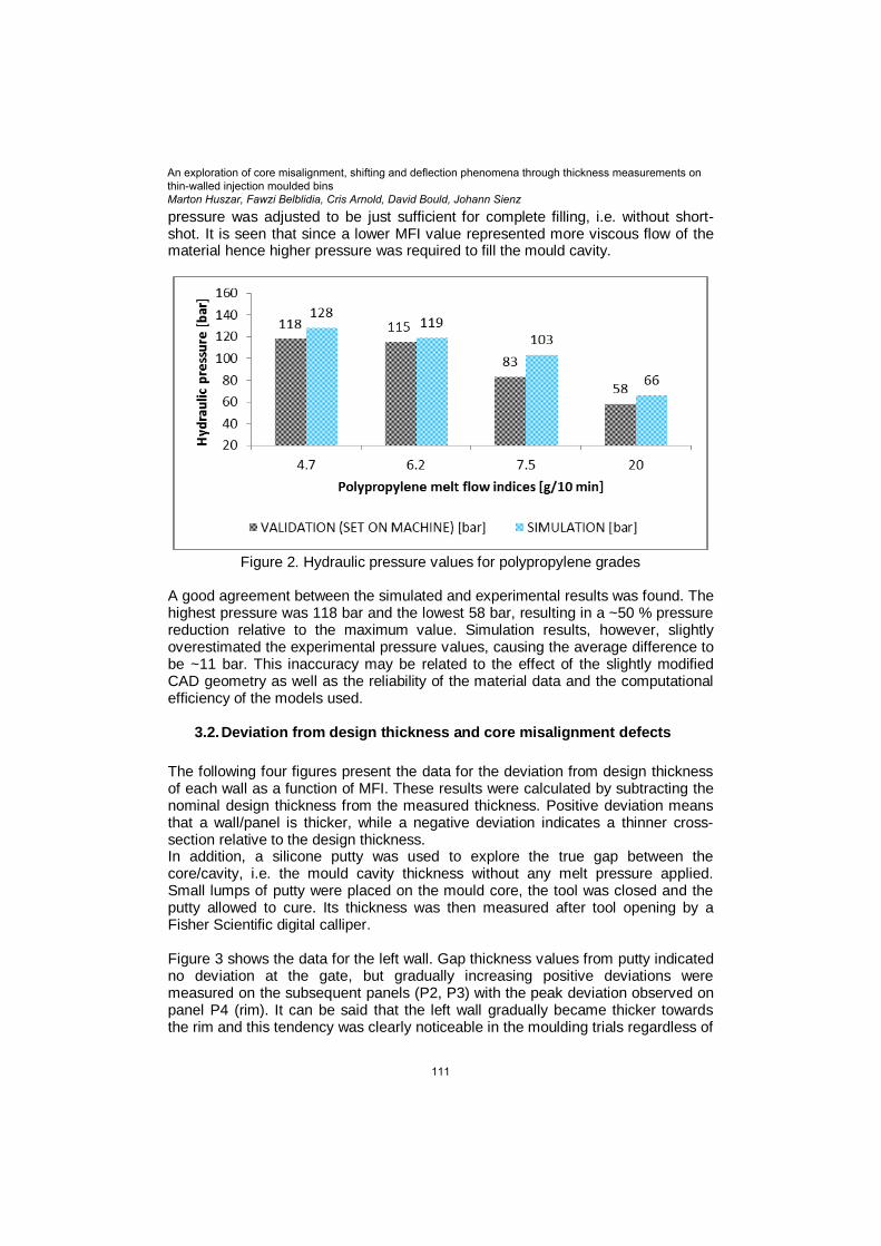
pressure was adjusted to be just sufficient for complete filling, i.e. without short-shot. It is seen that since a lower MFI value represented more viscous flow of the material hence higher pressure was required to fill the mould cavity.
Figure 2. Hydraulic pressure values for polypropylene grades
A good agreement between the simulated and experimental results was found. The highest pressure was 118 bar and the lowest 58 bar, resulting in a ~50 % pressure reduction relative to the maximum value. Simulation results, however, slightly overestimated the experimental pressure values, causing the average difference to be ~11 bar. This inaccuracy may be related to the effect of the slightly modified CAD geometry as well as the reliability of the material data and the computational efficiency of the models used.
3.2. Deviation from design thickness and core misalignment defects
The following four figures present the data for the deviation from design thickness of each wall as a function of MFI. These results were calculated by subtracting the nominal design thickness from the measured thickness. Positive deviation means that a wall/panel is thicker, while a negative deviation indicates a thinner cross-section relative to the design thickness. In addition, a silicone putty was used to explore the true gap between the core/cavity, i.e. the mould cavity thickness without any melt pressure applied. Small lumps of putty were placed on the mould core, the tool was closed and the putty allowed to cure. Its thickness was then measured after tool opening by a Fisher Scientific digital calliper. Figure 3 shows the data for the left wall. Gap thickness values from putty indicated no deviation at the gate, but gradually increasing positive deviations were measured on the subsequent panels (P2, P3) with the peak deviation observed on panel P4 (rim). It can be said that the left wall gradually became thicker towards the rim and this tendency was clearly noticeable in the moulding trials regardless of
An exploration of core misalignment, shifting and deflection phenomena through thickness measurements onthin-walled injection moulded binsMarton Huszar, Fawzi Belblidia, Cris Arnold, David Bould, Johann Sienz
111

what plastic grades were used. It can also be noted the lowest departure from the silicon putty data was experienced with grade MFI 20 g/10 min, increasing consistently as MFI falls to the lowest grade MFI 4.7 g/10 min.
Figure 3. Thickness deviation for left wall
Figure 4 describes the deviation on the right wall. The tendency was found to be the opposite to that on the left wall. The initial positive deviation at the gate was subsequently reduced to almost zero towards the rim. This suggested the cross-section would become the thinnest around the rim. As a function of different grades, a discrepancy in measured data was observed between panel P2 and P3 as well as P4 (rim). This thickness deviation might be attributed to core bending effect due to various pressures.
Figure 4. Thickness deviation for right wall
Figure 5 presents the data for the top wall. According to the silicone putty readings, the deviation on each panel was found to be positive meaning the top being thicker then the design thickness. On panel P3 however, there was a distinct drop in deviation. This occurrence might be attributed to core machining defect which would cause misalignment. Regardless of what plastic grades were used, the trends for deviation were identical with the thickness evolution of the silicone putty.
An exploration of core misalignment, shifting and deflection phenomena through thickness measurements onthin-walled injection moulded binsMarton Huszar, Fawzi Belblidia, Cris Arnold, David Bould, Johann Sienz
112

Figure 5. Thickness deviation for top wall
Considering the bottom wall, Figure 6 shows similarity to Figure 5. There was an initial positive deviation as it was seen with the top wall. After that, on panel P2 a further increment in deviation was followed by a drop on panel P3 which was apprioximately equivalent to the initial deviation observed at panel P1 (gate). At panel P4 (rim), the largest deviation occurred. The closest data points to the silicone putty were obtained by MFI 20 g/10 min, showing identical thickness evolution. Materials that MFI was 4.7 and 6.2 g/10 min showed the lowest deviation from design thickness. This is particularly well seen on panel P1 and P3 where the deviation was almost zero. It can be stated that core machining/manufacturing defect caused core misalignment which was well noticeable on the top and bottom walls.
Figure 6. Thickness deviation for bottom wall
The clarity of trends e.g. the effects of MFI (hydraulic pressure) suggests that differences in measured wall thickness were reproducible. Data presented are sufficiently precise that confirms the reliability of the calliper measurements. The standard deviations for different MFI grades and putty are presented in Table 2.
An exploration of core misalignment, shifting and deflection phenomena through thickness measurements onthin-walled injection moulded binsMarton Huszar, Fawzi Belblidia, Cris Arnold, David Bould, Johann Sienz
113

Table 2. Standard deviation of wall thickness measurements
MFI [g/10 min] / wall LEFT BOTTOM RIGHT TOP
4.7 0.030 0.019 0.012 0.018
6.2 0.018 0.032 0.016 0.021
7.5 0.021 0.030 0.018 0.009
20 0.019 0.027 0.019 0.014
MFI avg. std. deviation [mm] 0.022 0.027 0.016 0.015
Putty avg. std. dev. [mm] 0.018 0.026 0.024 0.021
Based on the previously introduced thickness data, it was presumed that the core misalignment on all four walls would cause unbalanced flow. It was therefore desired to look for indications of core shifting and deflection. Relevant data using the silicone putty is written in Table 3. It was found that the left and bottom walls were thicker relative to the right and top walls around panel P4 (rim). This was an indication for the existence of core shifting.
Table 3. Thickness values of the silicone putty
Symptom [mm] / wall LEFT RIGHT TOP BOTTOM
Core shifting - panel P4 (rim) 0.28 -0.01 0.09 0.24
Core deflection - panel P1 (gate) -0.01 0.09 0.15 0.11
As seen on Figure 3 - Figure 6, the wall thicknesses generally reduce as MFI falls. In the moulding trials, the hydraulic pressure (see Figure 2) was reduced to the minimum required to avoid short-shots for each material. It is suggested that the reduction in wall thickness for the lower MFI (more viscous) materials is a result of inadequate packing at the end of the flow path (panel P4 (rim)). The reduction in wall thickness from MFI 20 g/10 min to 4.7 g/10 min was 0.06 mm. The average wall thickness of these two grades was 1.74 mm, i.e. a reduction of 3.3 %, was a feasible difference due to uncompensated shrinkage. From Table 3, the sign of core deflection was also detected on panel P1 (gate). The right and top walls were measured to be thicker than the left and bottom walls. As a result, the higher melt pressure would deflect the core tip diagonally towards the left and bottom walls. It can be claimed that the asymmetrical alignment of the core was responsible for the formation of core shifting and core deflection.
3.3. Core shifting
It was needed to extend the study to explore the actual cavity gap relative to the silicon putty`s thickness. To achieve this, the actual cavity gap around panel P4 (rim) was calculated by subtracting the silicone putty`s thickness from the measured part thicknesses. For this evaluation, the MFI 6.2 g/10 min and the least viscous grade MFI 20 g/10 min were used.
An exploration of core misalignment, shifting and deflection phenomena through thickness measurements onthin-walled injection moulded binsMarton Huszar, Fawzi Belblidia, Cris Arnold, David Bould, Johann Sienz
114
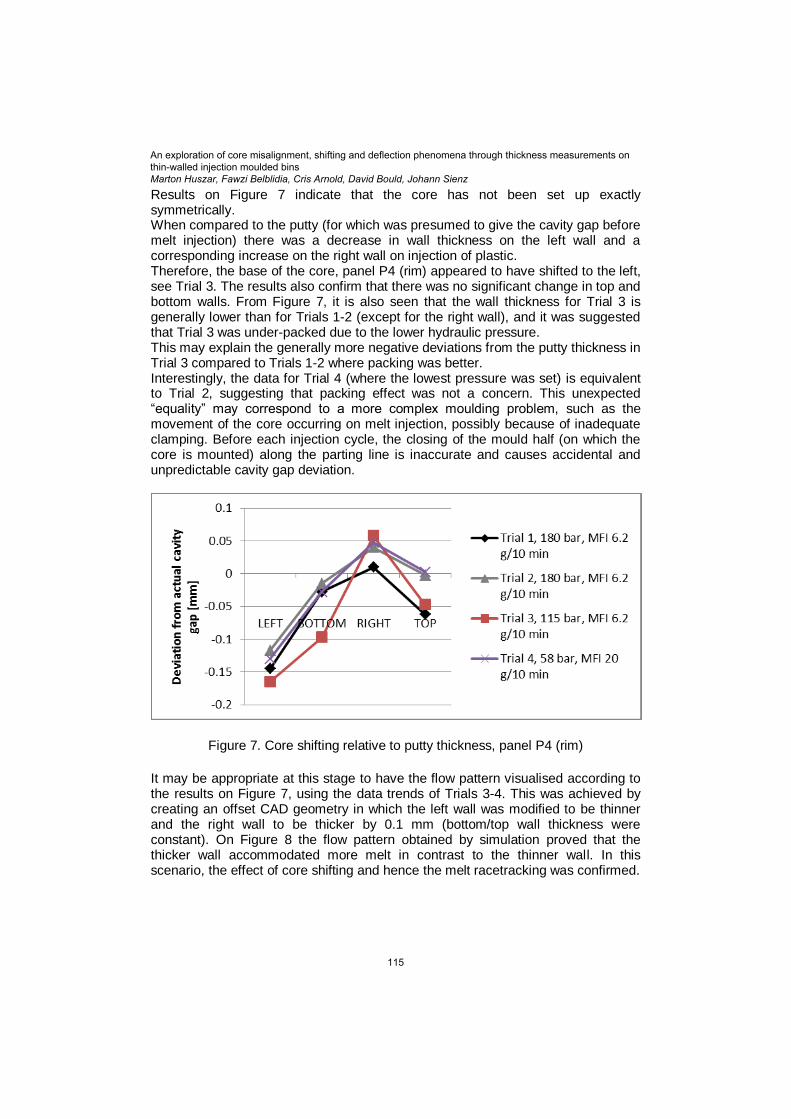
Results on Figure 7 indicate that the core has not been set up exactly symmetrically. When compared to the putty (for which was presumed to give the cavity gap before melt injection) there was a decrease in wall thickness on the left wall and a corresponding increase on the right wall on injection of plastic. Therefore, the base of the core, panel P4 (rim) appeared to have shifted to the left, see Trial 3. The results also confirm that there was no significant change in top and bottom walls. From Figure 7, it is also seen that the wall thickness for Trial 3 is generally lower than for Trials 1-2 (except for the right wall), and it was suggested that Trial 3 was under-packed due to the lower hydraulic pressure. This may explain the generally more negative deviations from the putty thickness in Trial 3 compared to Trials 1-2 where packing was better. Interestingly, the data for Trial 4 (where the lowest pressure was set) is equivalent to Trial 2, suggesting that packing effect was not a concern. This unexpected “equality” may correspond to a more complex moulding problem, such as the movement of the core occurring on melt injection, possibly because of inadequate clamping. Before each injection cycle, the closing of the mould half (on which the core is mounted) along the parting line is inaccurate and causes accidental and unpredictable cavity gap deviation.
Figure 7. Core shifting relative to putty thickness, panel P4 (rim)
It may be appropriate at this stage to have the flow pattern visualised according to the results on Figure 7, using the data trends of Trials 3-4. This was achieved by creating an offset CAD geometry in which the left wall was modified to be thinner and the right wall to be thicker by 0.1 mm (bottom/top wall thickness were constant). On Figure 8 the flow pattern obtained by simulation proved that the thicker wall accommodated more melt in contrast to the thinner wall. In this scenario, the effect of core shifting and hence the melt racetracking was confirmed.
An exploration of core misalignment, shifting and deflection phenomena through thickness measurements onthin-walled injection moulded binsMarton Huszar, Fawzi Belblidia, Cris Arnold, David Bould, Johann Sienz
115

Figure 8. Simulation of the core shifting effect using the offset geometry
3.4. Core deflection
It was anticipated that the core shifting data alone would not provide satisfactory information concerning the flow evolution, hence the contributing effect of core deflection was also studied. The analysis is restricted to the discussion of the deflection occurring at the closest panel to the injection location (panel P1) as a function of MFI. Results were calculated by subtracting the silicone putty`s thickness from the measured part thicknesses (based on the same principle as discussed with core shifting, see Figure 7). On Figure 9 it is noticeable that lowering the hydraulic pressure helped to increase the cavity gap on the left and bottom walls. This recognition suggests that higher pressure tended to deflect the core tip towards the left and bottom walls diagonally. Reduction in pressure (i.e. using higher MFI grades) took the melt pressure off the core, causing it to regenerate towards the right and top walls, hence the drop in deflection. Similarly to core shifting, core deflection can also account for melt racetracking. Owing to higher pressure applied, a larger cavity gap on the right and top walls would allow more melt to flow into those sections. The core deflection at the gate tip towards left and bottom walls with the lowest MFI is ~ 0.1 mm. The core length is ~ 410 mm, the angular deflection is ~ 0.01 °.
Figure 9. Investigation of core deflection as a function of MFI at panel P1 (gate)
LEFT TOP
RIGHT
BOTTOM
An exploration of core misalignment, shifting and deflection phenomena through thickness measurements onthin-walled injection moulded binsMarton Huszar, Fawzi Belblidia, Cris Arnold, David Bould, Johann Sienz
116

3.5. Flow pattern evolution
It has been discussed that the existence of multiple problems, such as core shifting and deflection were responsible for the formation of deviation in part-thickness. A final experiment was carried out to validate the findings regarding core shifting and deflection. In this context, a short-shot sample, produced at 100 bar hydraulic pressure using the MFI 6.2 g/10 min grade allowed investigating the flow evolution under real-life conditions. The screenshot of panel P4 (rim) is displayed on Figure 10, confirming the racetracking effect and the reliability of thickness measurements. As discussed, the left wall was found to be the thinnest. It can be stated that as the cavity gap on the left wall decreased, the gap on the right wall increased. A clear indication was found to support this statement as illustrated on Figure 8. Still on the basis of core shifting data, it was expected that an equal amount of melt would flow along the cavity on the bottom and top walls; however it was not the case. As it was mentioned, core tip deflection was occurring diagonally towards the left and bottom walls, see Figure 9. As a result, more melt was allowed to enter the cavity on the top wall, causing a more advanced melt flow relative to the bottom wall. In addition, the flow front on the right wall showed gradual advancement when getting closer to the top wall.
Figure 10. Flow pattern of a short-shot sample, displaying panel P4 (rim)
4. Conclusions
The hydraulic pressure values linked to the thickness measurements taken on the silicone putty and moulded parts revealed deviations from the original design thickness. The root cause of the wall thickness deviations is that the core has not been set up exactly symmetrically in the cavity. As a consequence of core misalignment, core shifting and deflection were noticeable. Core shifting was confirmed when investigating panel P4 (rim). The shifting effect in relation to the silicon putty revealed that the left wall was measured to be thinner and the right wall to be thicker. Offset is of the order of ~ 0.1 mm, but appears nevertheless to be sufficient to result in unbalanced melt flow around the core, producing unbalanced pressures acting on it. The cavity gap on the bottom and top walls was found to be equivalent. Core deflection at panel P1 (gate) was present, where the pressure deflected the core tip diagonally towards the left and bottom walls. The melt flow evolution of a short-shot moulded sample confirmed the existence of melt racetracking and the coupled effects of core shifting and tip deflection.
TOP
LEFT BOTTOM
RIGHT
An exploration of core misalignment, shifting and deflection phenomena through thickness measurements onthin-walled injection moulded binsMarton Huszar, Fawzi Belblidia, Cris Arnold, David Bould, Johann Sienz
117

It can be noted that the situation has been inherently unstable. Initial non-uniformity in the cavity gaps is enhanced by unbalanced melt flow. The hydraulic pressure was proved to be an efficient parameter to reduce the thickness discrepancies arising from core deflection, but is constrained by the required material grade and the necessity for sufficient packing. No convincing evidence was found whether core shifting could be controlled by altering the hydraulic pressure. From a sustainable production point of view, it is critical to ensure that the core is machined and aligned correctly in the mould. If a more uniform part-thickness was achieved this would allow tighter geometrical tolerances which could lead to a reduction in part weight, without compromising the mechanical properties. Reducing the quantity of material resources will enable lower energy consumption and the amount of production waste (less recycling issues). In terms of social aspects, a well-designed high quality product should enhance customer satisfaction and long-term company reputation. Therefore, the periodical monitoring of core alignment is paramount to ensure that the highest quality products are produced.
5. Acknowledgements The authors are grateful for the project contribution of John Pittman and Patrick Wlodarski. The continuous technical support of John Davies, Alan Leach and Mark Langford has also been highly appreciated. The authors also would like to acknowledge the support of the Advanced Sustainable Manufacturing Technologies (ASTUTE) project, which is part funded from the EU’s European Regional Development Fund through the Welsh European Funding Office, in enabling the research upon which this paper is based. Further information on ASTUTE can be found at www.astutewales.com.
6. References
[1] A. Bakharev, Z. Fan and F. Costa, “Prediction of core shift effects using mold filling simulation,” ANTEC, pp. 621-625, 2004.
[2] A. J. Giacomin, A. J. Hade, I. M. Johnson, A. W. Mix, Y.-C. Chen, H.-C. Liao and S.-C. Tseng, “Core deflection in injection moulding,” Journal of Non-Newtonian Fluid Mechanics, vol. 166, pp. 908-914, 2011.
[3] J. Shoemaker, MoldFlow Design Guide, Hanser Gardner Publications Inc., ISBN-13: 978-1-56990-403-9, 2006.
[4] A. B. Glanvill and E. N. Denton, “Injection-mould design fundamentals,” Industrial Press, pp. 221-225, 1965.
[5] X. Guo, “Plastics Mold Design,” Qinghua University Press, pp. Chapter 6, page 90, 2006.
[6] R. Wurst and B. H. Watkins.United States of America Patent 5,972,256, 1999.
[7] R. T. Gilbert and I. B. Pfau.United States of America Patent 4,126,291, 1978.
[8] Y.-C. Chen, Y.-J. Liao, S.-C. Tseng and A. J. Giacomin, “Core deflection in plastics injection molding: Direct measurement, flow visualization and 3D simulation,” Polymer - Plastics Technology and Engineering, vol. 50, pp. 863-
An exploration of core misalignment, shifting and deflection phenomena through thickness measurements onthin-walled injection moulded binsMarton Huszar, Fawzi Belblidia, Cris Arnold, David Bould, Johann Sienz
118

872, 2011.
[9] Y.-Y. Chou, Y.-J. Chang and A. Giacomin, “http://www.moldex3d.com/en/assets/2011/09/Melt-Memory-and-Core-Deflection.pdf,” CoreTech System (MoldEx3D) Co., Ltd., Taiwan. [Online]. [Accessed 22 11 2013].
[10] M. A. Rosen and H. A. Kishawy, “Sustanable Manufacturing and Design: Concepts, Practices and Needs,” Sustainability, vol. 4, pp. 154-174, 2004.
[11] L. Smith and P. Ball, “Steps towards sustainable manufacturing through modelling material, energy and waste flows,” Intl. J. Production Economics, vol. 140, pp. 227-238, 2012.
[12] P. Kennedy, Flow analysis of injection molds, Hanser Publishing, ISBN 3-446-18050-8, 1995.
[13] R. Pantani, I. Coccorullo, V. Speranza and G. Titomanlio, “Modeling the morphology evolution in the injection molding process of thermoplastic polymers,” Prog. Polymer Science, vol. 30, pp. 1185-1222, 1995.
[14] H. Zhou, Computer modeling for injection molding: simulation, optimization and control, John Wiley & Sons Inc., ISBN 978-0-470-60299-7, 2013.
An exploration of core misalignment, shifting and deflection phenomena through thickness measurements onthin-walled injection moulded binsMarton Huszar, Fawzi Belblidia, Cris Arnold, David Bould, Johann Sienz
119