an experimental study of pressure gradients for flow of ... · the present report contains the...
TRANSCRIPT

AE-85
CO
w<
An Experimental Study of Pressure
Gradients for Flow of Boiling Water
in Vertical Round Ducts (Part 3)
Kurt M. Becker, Gunnar Hemborg
and Manfred Bode
This reporf is intended for publication in a periodical. Referencesmay not be published prior to such publication without theconsent of the author.
AKTIEBOLAGET ATOMENERGISTOCKHOLM SWEDEN 1962


AE-85
AN EXPERIMENTAL STUDY OF PRESSURE GRADIENTS FOR FLOW
OF BOILING WATER IN VERTICAL ROUND DUCTS (Part 3)
by
Kurt M Becker, Gunnar Hernborg and Manfred Bode
Summary
The present report contains the results of the third phase of an
experimental investigation concerning frictional pressure gradients for
flow of boiling water in vertical channels. The test section for this phase
consisted of an electric heated stainless steel tube of 3120 mm length and
3,94 mm inner diameter.
Data were obtained for pressures between 8 and 41 ata, steam
qualities between 0 and 58 %, flow rates between 0,0075 and 0,048 kg/sec
and surface heat flux between 20 and 83 W/cm .
The results are in excellent agreement with our earlier data for flow
in 9, 93 and 7, 76 mm inner diameter ducts which were presented in AE-69
and AE-70.
The present measurements substantiate our earlier conclusion that
the nondimensional pressure gradient ratio, *f , is, in the range investi-
gated, independent of mass flow rate, inlet subcooling and surface heat flux.
On the basis of the measured pressure gradients, the following
empirical equation has been established for engineering use.
This equation correlates our data (about 800 points) with a discrepancy less
than - 15 per cent and is identical with the c
from measurements with the 7, 76 mm duct.
than - 15 per cent and is identical with the corresponding equation obtained

LIST OF CONTENTS
Page
I. introduction '3
Preliminary Runs .3
3. Range of Variables 4
4. Results and Discussion 5
5. Pressure Drop Correlation 6
6. Conclusions 6
Nomenclature 8
Bibliography 9
This report is intended for publication in a periodical. References may
not be published prior to such publication without the consent of the author

1. Introduction
The purpose of the present report is to summarize the results ob-
tained during the third phase of an experimental study of frictional pressure
gradients for flow of boiling water in vertical round ducts of 3120 mm
heated length.
The first and second phases of the investigation dealt with ducts of
9,93 mm and 7, 76 mm inner diameters. The results from these phases
were presented in AE-69 (1) and AE-70 (2). The data of the present report
have been obtained using a duct of 3, 94 mm inner diameter. The experi-
mental techniques employed for studying the 3,94 mm duct have been identi-
cal with the techniques earlier used for the 7, 76 mm duct. A description
of the apparatus, instrumentation and method of testing is therefore omitted
in the present report, and the readers are referred to AE-69 and AE-70.
The total experimental programme includes also a duct of 12,99 mm
inner diameter^ "When this programme is completed a final report will be
writtens where all the data will be discussed and compared to two phase flow
pressure drop data in the literature.
No detailed discussions will therefore be presented in the present
report. Only brief comments will be given with reference to the figures
showing the experimental results. For better understanding of the data,
the reports AE-69 and AE-70 should therefore be consulted.
2. Preliminary Runs
For checking the accuracy of the experimental techniques the follow-
ing preliminary runs were made
1. One-phase flow friction coefficients
2. One-phase flow heat transfer
3. One-phase flow heat balances
Figure 5 shows the measured friction coefficients which are corre-
lated with an average discrepancy of + 1 % by the equation
f = 0,229 Re~°'2 1 9 (1)

Figure 6 shows the measured Nusselt numbers compared to the well-
known McAdams equation. Our data are on the average about 15 per cent
lower than the equation.
The results from the heat balance measurements are given in the table
below.
Run
1
2
3
4
5 •
mkg/sec
0,0574
0,0360
0,0627
0, 0494
0,0255
Net Heat InputkJ/sec
17,2
10,85
23,13
10,92
8,0
waterkj/sec
17,4
10,8
23,08
10,92
7 , 9
Erro
- 1,2
+ 0,5
+ 0,2
0
+ 1,2
The accuracy of the heat balances are excellent.
3. Range of Variables
Series of runs were made at fixed values of pressure, p, and heat
flux, q/A. For the heat flux, values of approximately 33, 50 and 70 W/cm
were selected. For a heat flux of 33 W/cm the lowest pressure obtainable
at the entrance of the test section was~10 ata. The corresponding pressures
for heat fluxes of 50 and 70 W/cm were 14 respectively 20 ata. The maximum
operating pressure was 40 ata, and the test series were then performed
for the values of q/A and p shown in the table below.
q/A (W/cm2)
20
33
50
70
83
p (ata)
20
10, 20, 30, 40
14, 30, 40
20, 30, 40
30

It should be noted that one test series was also performed at a heat
flux of 20 W/cm'' and a pressure of 20 ata, and one series at a heat flux
of 83 "W/cm and a pressure of 30 ata.
Each series consisted of 4-7 runs with different mass flow rates.
The mass flow rate for all runs was in the range from 0, 0075 kg/sec to
0, 048 kg/sec.
With these values of the mentioned parameters steam qualities between
0 and 0, 58 were obtained in the test section.
The total experimental programme for the two-phase flow measure-
ments consisted of 88 runs.
4. Results and Discussion
In figures 8 to 11 the measured frictional pressure gradient ratio..
*$ , is plotted against the steam quality, x, with the static pressure as
parameter. The relatively large deviations from the mean pressures
given in the diagrams are mainly caused by the axial pressure gradients
in the test section.
Figure 12 shows a summary of the data presented in figures 8 to l lo
j -values at x = 1,0 computed by means of one-phase flow theory are
also given, as well as the results by Martinelli and Nelson (3).
In figures 13 and 24 our results are plotted according to the method
by Lockhart. and Martinelli (4), using ^ ' andX as variables.
Our conclusion in AE-70 that the mass flow rate has no effect on the
j -values is completely verified by examining the data in the figures..
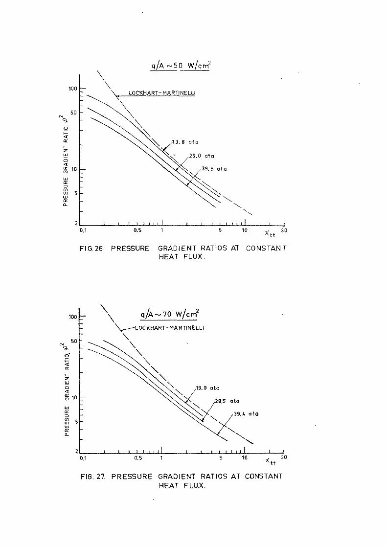
Figures 25, 26 and 27 show data obtained at fixed heat fluxes, but
different pressures. Comparing these figures with figures 30, 31 and 32
of AE-69 and figures 25, 26 and 27 of AE-70, almost identical pressure
relationships are found for all three ducts.

Figures 28 and 29 give results from runs with different heat fluxes,
but with almost constant pressures. As for the 9,93 and 7, 76 mm ducts,
no effect of surface heat flux has been observed in the range investigated.
5. Pressure Drop Correlation
Using the same method as for the 9, 93 and 7, 76 mm ducts, a pressure
drop correlation has also been derived on the basis of the experimental
results obtained with the present duct. From the curve in figure 30 and
figure 39 of AE-69 we arrived after some simplifications at the follow-
ing empirical equation
^ Z = 2400 ( - ) ° ' 9 6 + 1 (2)
This equation is identical with equation 1 of AE-70, valid for the 7, 76 mm
duct.
Figure 31 shows a plot of arbitrarily selected \P -values against the
ratio x/p. The solid line represents equation 2. The equation correlates
the data within an accuracy of + 15 per cent.
A plot of the measured *f -values against the values for f computed
by means of equation 2 is given in figure 32.
Figure 33 shows a comparison between equation 2 and our data ear-
lier presented in figures 8 to 11. The agreement between the equation and
the data is excellent.
A more detailed discussion of the data and the literature on the subject
will be given in the final report concerning all the diameters investigated.
6. Conclusions
Frictional pressure drops for flow of boiling water in a round vertical
duct of 3, 94 mm inner diameter have been measured for a large range of
variables.

In the limiting cases of x = 0 and x = 1,0, our data are in
excellent agreement with one phase flow theory.
In the two phase flow region the present data are in excellent
agreement with our earlier results obtained with 9, 93 mm and 7, 76 mm
ducts, and our conclusions arrived at in AE-69 and AE-70 have been
verified.
We conclude that in the range investigated inlet subcooling, surface
heat flux and mass flow rate have no effect on the frictional pressure
gradient ratio j .
With regard to the diameter effect the difference in results for the
three ducts studied up to now is so small, that we conclude that for
engineering purposes the effects of changing the diameter in the range
investigated is negligible.

Nomenclature
Symbol
f
Nu
m
P
Pr
q/A
Re
x
X t t
Definition
Friction coefficient
Nusselt number
Mass flow rate
Pre s stir e
Prandtl number
Heat flux
Reynolds number
Steam quality
Pressure gradient ratio
Parameter defined by eq. 12ref. (1)
Unit
Dimensionless
Dimensionle s s
kg/
kg/
s e c
c m
Dimensioniess
W/cm2
Dimensionless
kg/kg
Dimensionless
Dimensionless
• Bibliography
1. Becker K M, Hernborg G and Bode M,
An Experimental Study of Pressure Gradients for Flow of Boiling
Water in a Vertical Round Duct (Part 1), Report AE-69, March 1962.
2. Becker K M, Hernborg G and Bode M,
An Experimental Study of Pressure Gradients for Flow of Boiling
Water in a Vertical Round Duct (Part 2), Report AE-70, March 1962.
3. Martinelli R C and Nelson D B,
Prediction of Pressure Drop during Forced Circulation Boiling of
Water, Trans. ASME, vol. 70, 695, 1948.
4. Lockhart R W and Martinelli R C,
Proposed Correlation of Data for Isothermal Two Phase, Two
Component Flow in Pipes, Chem. Eng. Progress, Vol. 45, 39, 1949.


MAKE UPWATER
CONDENSER
TO DRAIN
MANOMETER
T ) OUTLET TEMPERATURE" THERMOCOUPLE
I — - 7 ELECTRODES
FEED PUMP
CIRCULATINGPUMP Ö
3.94 MM |.D. TESTSECTION
^ 2 x 1 2 COPPER-CONSTANTAN/ THERMOCOUPLES
INLET TEMPERATURETHERMOCOUPLE
MANOMETER
TO U-TUBE
WATERCOOLER
PREHEATER
*—\ V^FLOWMETER CERAMIC AMD
MAGNETIC FILTER
RG. t FLOW DIAGRAM.

COORDI-NATE
31903165'30753035299529058815277527352697264525552475242723852295221521892125203519631955189518651855181517751747173516951655I6l51605157515341515147514351395135513451321131512551215117511351107IO85995915
825735655641565k75
43539537430521513545200
ELEC-TRODE TAP
r10
r12
r13
THERMO-COUPLE
121
12121
211
211
21
a12111.
211121
111,112
11111
211
211
2121
2112
MARK
toTA1, TA2,TA3
TA4TS1, TB2,TB3
TB4
TCI, TC2TC3TC4
TD1, TD2,TD3TD4
TE1, TE2,TE3
TE4
TF1, TF2,
TF?
TI21,TI22TF4
TGI, TG2,
TG3
TG4
TH1, TH2,
TH3
TH4
TJI, TJ2,TJ3TJ4
TK1, TK2,TK3TK4
T U , TL2,TL3TI31,TI32TL4
TM1, TM2,TM3TM4TNI, TN2,
SECTION
B
•p ^ ^
o- TA3
- TA4
- TB3
- TB4
p, —
Pi, -
PQ -
TC3
TC4
TD3
TD4
TE3
TE4
TP3
TP4
TG3
TG4
- TH4
TJ3
TJ4
TK3
TK4
- TL3
- TL4
- TM3
- TM4
FI6.2. LOCATION OF ELECTRODES, PRESSURE TAPSAND THERMOCOUPLES ON TEST SECTION.
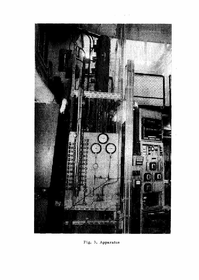
Fig. 3. Apparatus
130
125
120
115
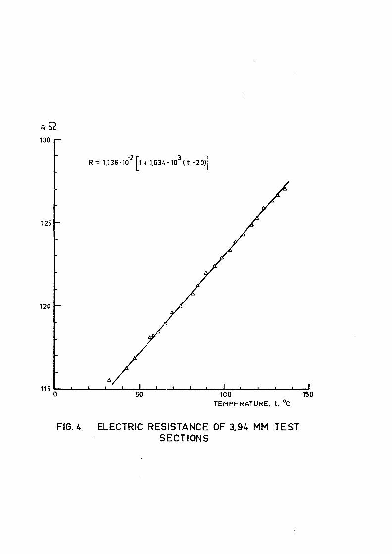
R= 1.136-10"2 Pi + 1.034-103{t-20)l
50 100TEMPERATURE, t. °C
150
FIG. 4. ELECTRIC RESISTANCE OF 3.9£ MM TESTSECTIONS

5-KT 10" 510*
REYNOLDS NUMBER i V /
FIG. 5. FRICTION COEFFICIENTS FOR ISOTHERMAL FLOW OFWATER IN 3.94 MM DUCT.
500
o
-SL
100
50
20
Nu= 0.023- 15°/o
r » • ' L
5-1Ö4 10S
REYNOLDS NUMBER,
3-105
FIG. 6. HEAT TRANSFER RATES FOR ONE PHASEFLOW OF WATER.

PBAft
21.0-
20.5-
t'C
160
RUN 3MASS FLOW RATE m » 0.0150 kg/sHEAT FLUX, q/A » 33.27 w/cm2
BULK TEMPERATURE. t Q
0.20-
0.10-
0 -
02-0.10-
-0.20-i
vSECTION
14QMAM3
120P13
M M
0
/ LA L3 KA
P12 P11
| L K
,500
K3 JA
P10
| .
J3 HA
P9
1 | H
1000
H3
P
GA
8
G
G3 FA
P7
F3 E
P6
F
1S00
A E3 DA
PS PA
• E D
2000
D3 CA C3
P3
I ',2500
8A
P2
B
B3 AA A3Z-COORDINATE
P1
A(3000
FIG. 7. PRESSURE, TEMPERATURE AND STEAM QUALITY DISTRIBUTIONS ALONG TEST SECTION.

! 1
= 9.75 ± 1
RUN,
o 22a 23v 24o 25x 26
.8
<ij
ata/A(w/cmZ),
34.5434.4134.6534.5734.78
m(kg/s)
0.01870.01520.01330.01190.0110
t t 1
0 0.1 0.2 0.3 0.4 0.5 0.6 0.7 0.8
STEAM QUALITY, x
F!6.8. MEASURED PRESSURE GRADIENT RATIOS.
I _
MARTINELLI-NELSON
t 3.0 ata
RUN, q/ACW/cm2),
oAV
9X
o6
t,
1235
525354566768
33.4833.3233.2733.1220.6120.5920.6469.9670.2270.66
0.02420.01990.01500.01090.00980.00880.00750.033?0.02980.0249
t 10.1 02 03 Of, 0.5 0.6 0.7 0.8
STEAM QUALITY, x
FIG. 9. MEASURED PRESSURE GRADIENT RATIOS.

o
o
9-
10,
i—
oth-inZUiQ
CCtaU lCC
COUIaca.
-
-
— i
" Ur~ il
v_ - »
i i i
iy/K MARTINELLI-& NELSON
Y<
i i i
1
o&vQ
X
+6
•o
1
1
28.8 tRUN,
111213373839647374
I
I
4-
2.8 ata
q/A(w/cm2),
32.5732.5732 5050.0350.5750.3482.427 0.486 9.47
1
1
-
—
m{kg/s)
0.01340.01150.00980.01600.0144 _0.01250.0293 ~"0.0201 -0.0177
—
—
1 t
0 0.1 0.2 0.3 0.4 0.5 0.6 0.7 0.8
STEAM QUALITY, x
FIG. 10. MEASURED PRESSURE GRADIENT RATIOS.
o
sT
\~M—inO
DC
CO
DC
COCO
PRE
-
-
— £- v/'- 4/
- /_ //- c
I
I
1 i
/
1
- * * !
1
MARTINELL1-NELS0N
p =
oA
V
a
i.
66.6
1
40.2 t
RUN,
181920798081868788
1
1.6 ata
q/A(W/cm2)
32.0631.9531.9068.8869.0668.134 8.324 7.854 8.06
1
1 1
—-—
—
_—
m(kg/s) _
0.0131 —0.0106 _0.00960.0202 —0.01850.0161 _0.01570.01310.0123
| I0.1 0.2 0.3 0.4 05 0.6 0.7 0.8
STEAM QUALITY, x
FIG. 11. MEASURED PRESSURE GRADIENT RATIOS.

p = 9.6p = 19.5p = 28.8
GO p = 40.2
PRESENT RESULTSMARTINELU- NELSON
10 20 30 50 60 70 80 90,- STEAM QUALITY, x %
FIG.12. COMPARISON WITH THE MARTINÉLLI AND NELSON METHOD.
100
100 r
cc
zUJ
<cco 10Hi
ccininacQL
5 -
~ \ LOCKHART-I \ MARTINELLI
- #\^
i i i i i • i i I
p —19. 9 t
RUN,
D 51* 52» 53° 54
i i i i i
0.8 ota
q/A(w/cm2}
20.4920.612 0.592 0.64
\*»s ^
. . .1
m{kg/s)
0.01340.0 0980.0 0880.0075
0.1
FIG. 13.
0.5 1 10 30
MEASURED PRESSURE GRADIENT RATIOS.

100
.50
10
5
2
\- \- SL \
- ^M. \ LOCKHART-\ \ MARTINELLI
" Nk
_
i i i i, i t i l .— -
P =
•
A9o
I 1
9.6 • 1.
RUN,
212223242526
8 ata
q/A(w/cm2)
3 5.1634.5434.4134,6534.5734.78
\
I I I I I
m(kg/s
0.02420.01870.01520.01330.01190.0110
0.1 0.5 1
FIG. H.
10 Xtt 30
100
-50o
en
CD
LU
ceCOcnmcea.
10
111
p = 19. 9 t 0.8 ata
RUN, qkw/cm2), m(Ug/s)
o 1 33.4 8 0.02422 33.32 0.01993 33.27 0-01504 33.22 0.01305 33.12 0.01096 3296 0.0097
0.1
FIG. 15.
0.5 10 X 30tt
MEASURED PRESSURE GRADIENT RATIOS.

100
10
50
o
cc
o
10UJ
a.
ina.
32.943 3.0133.01
88
p = 29.91 1.1 ata
RUN, q/Atw/crr2), m(kg/s)
0.02270.02500.01920.01590.01340.01150.0098
i i i i , . . . I0.1 10
* t t30
FIG. 16.
100
50
<ac
t—
<£10WIf)
8! s
LOCKHART-
MARTINELLI
p -
oA
V
9ö
• o
o
39.1 ± 1RUN,
U151617181920
.1 ataq/A(W/cm2),
32.8132.5232.2932.1932.0631.9531.90
m(kg/s
0.02850.02190.01760.0U30.01310.01060.0096
0.1 0.5 10 30
FIG. 17. MEASURED PRESSURE GRADIENT RATIOS.

100
50
o
1—
52 10
U)
a:
a:a.
LOCKHART-MARTINELLI
1 1 1 1 1 1 1
p =
o
6
ov
<?
13.8 tRUN,
404142434445
1.5 ataq/A(w/cm2)
52.4451.8151.7451.6151.5351.22
m(kg/s
0. 03120.02540.02180.02000.01770.0157
1 XJ01 0.5 10 X tt
30
FIG. 18.
100
o<a:
UJQ<
a:
trIDtn01
CL
p=29.0 11.3 ata
RUN, q A{W cm2),
50.6051.0150.0850.0350.5750.34
L0CKHART-MARTfNELLI
_L _L , I I . , , ! , 1 , 1 , 1 JL J I I 1 I
rh(kg s)
0.02850.02290.0191 .0.01600.014 40.0125
J0.1 0.5 1 5 10 ^ 30
FIG.19. MEASURED PRESSURE GRADIENT RATIOS.

100
' ^ 5 0
ö*
on
zLUO
cc° 10tuOf
CO
ut 5
a.
2
\
~ \ LOCKHART-I V MARTINELLI
" ^X \
>*, X** X^\, \
t i l l
p =
oA
V
96o
XX.
r \XXXa
\ 1
39.5 t
RUN,
838485868788
\
\
i i
1.2 ota
q/A(W/cm2),
49.0748.2148.4248.3247.8548.06
\
1 ! 1 1 I
rh(kg/s)
0.02460.02010.01740.01570.01310.0123
i j
0.1
Fl6. 20.
0.5 10*tt 3 0
MEASURED PRESSURE GRADIENT RATIOS.
ioo r
^ 5 0
UJ
o
i ioOJO£
tnoou
5 -
_ \\ LOCKHART-
I V MARTINELLI
wXX
1 I
1
1
1
1
, , 1
p=19.0 t
RUN,
o 65A 66v 67o 68
3.0
q/A{W/cm2}
70.2069.9670.2270.66
\
, , , , I
m{kg/s)
0.04300.03370.02880.0249
i i
0.1 0.5 1
FIG. 21
10Xtt
30

ef
a:
toQ
or
LUOC
CDenIxlcca.
100
50
10
5
2
\ LOCKHART-\ MARTINELLI
^a \
x\N* x- >i,
-
1 1 1 1 t 1 ! 1 1
P =
O
&
V
96o
\
28.5 tRUN
697071727374
\
\
. 1 1
2.0 otoq/A(W/cm2)
71.6571.4970.9870.2570.4869.4 7
\
a \ .
1 1 1 I
m(kg/s)
0.04220.03400.02640.02370.02010.0177
I ,..J0.1 0.5 10 30
FIG. 22. MEASURED PRESSURE GRADIENT RATIOS.
100
50
5-
Qi
1—2UJQ< 10a:oLUaif) 5toLU(X.CL
2
\
~ \ LOCKHART-\ MARTINELLI
"*%«. \
^NA X
---—-
i i i i i i 111
p =39.4 t 1.
A
V
96o
-oo
X\k x.*K \
\
i j_
RUN,
76
777879808175
1 i i
6 ataq /A(W/cm2
68.7 769.0869.0368.8869.0668.1369.21
I °i i i i
), * ( k g / s
0.03120.02660.02260.02020.01850.01610.0340
i i
0.1 0.5 10 V 30
FiG. 23. MEASURED PRESSURE GRADIENT RATIOS.

100
50
<
UJO
2ff.O 12.5 otaRUN, q/Atw/cm2) m(kg/s)
o 61 83.53 0.04760.0i390.03770.0293
626364
8i.l 862.6582.4 2.
10CKHART-MARTINELLI
1 i i t i r i I
0.1 0.5 10 30
FIG. 2A. MEASURED PRESSURE GRADIENT RATIOS.
qk ^ 33 W/cm2
100
EC
h~ZUJoacauiac
uata.
10
• LOCKHART-MARTINELLI
i t i i I
0.1 0.5 1 5 10 30
FIG. 25. PRESSURE GRADIENT RATIOS AT CONSTANTHEAT FLUX
100
50
10
5
2
\
—
_
I [
q/A w/
LOCKHART-MARTINELLI
i i i i i i 1
•13.8 ata
i
cm
0 ata
/39.5
I ;
ata
i i i i 11 i i0.1 0.5 1 10 v 30
"MtFIG. 26. PRESSURE GRADIENT RATIOS AT CONSTANT
HEAT FLUX.
100
50
o
cc
UJQ<
g 10iLlocz>
UJ
a.
q/A-70 w/cm
LOCKHART- MARTINELLI
t 1 1 1 1 1 1 t i t i i i i I0.1 0.5 1 10 30
-tt
FIG. 27. PRESSURE GRADIENT RATIOS AT CONSTANTHEAT FLUX.

OCO
cc
COenUJ
a.
100
50
10
5
2
I 33 W/
/ , 271 W/cm
i t
cm
s•
1
p ~
) W/cm
\>
i i i
30ota
2
V
.1 • . .
/ 8 3 W/cm2
V[ 1 1 1 1 1 1
0.1 0.5'tt
FIG. 28.
100
5 50
QC
I—ZUJQ
ceID
% 10COCOUJ
a:Q_
0.1
ata
0.5
FIG. 29. EFFECT OF HEAT FLUX ON PRESSUREGRADIENT RATIOS.

100
50
o
fl
X
o 10
5
2
—
l t
1 i
t
—
-
i 1 i l i i i
qJAW/crtf)
o 339 50o- 71o 83
PRESENT' RESULTS
[Q_ SHER AND 6REEN
Q
1 l i i i i i i 1 i {
10 50 100 300
PRESSURE, p ata
FIG. 30. EFFECT OF PRESSURE ON PRESSUREGRADIENTS.
100
50
10
5
1
i i i i I i | .i
-
-
1 i i i i i 1 (
i i
O (
Å
^\
1 ' ' ' ' 1 ' ' • ' • ' • '
15 °/o LIMIT , , / / /
I I
I I
ml
2 v 0 96"••• <p = 2400(—) ' + 1
P ~
i i i i i I l i ) i l i i l
0.001 0.01 0.1RATIO OF STEAM QUALITY TO PRESSURE, X / P crrf/kp
FIG. 31. PRESSURE DROP CORRELATION.

100
50
10
5
1
I
yy x i i t i m i
c
15 %
i
LIMIT S//
1 1
1 i
i
—
1 t
i t
i
I 1 1 | 1 1 1 1 15 10 50 100
FIG. 32. MEASURED PRESSURE DROP RATIO VERSUSCOMPUTED PRESSURE DROP RATIO.

9.7S ato
19.5 ata
40.2 oto
137 ata
EXPERIMENTAL RESULTS
EQUATION
1 I0 0.05 0.10 0.15 Q20 02S 0.30 0.35 WO (US 0.50 0.55 0.60 0.65 0.70 0.75
STEAM QUALITY, x
FIG.33. COMPARISON BETWEEN PRESSURE DROP CORRELATION AND EXPERIMENTAL RESULTS.
aso


LIST OF PUBLISHED AE-REPORTS
1—9. (See Ihe back cover of earlier reports.)
10. Equipment for thermal neutron flux measurements in reactor R2. By E.Johansson, T. Nilsson and S. Claeson. 1960. 9 p. Sw. cr. 6:—.
11. Cross sections and neutron yields for U235, Uö s and Pu2* at 2200 m/sec.By N. G. Sjöstrand and J. S. Story. 1960. 34 p. Sw. cr. 4:—.
12. Geometric buckling measurements using the pulsed neutron source me-thod. By N. G. Sjöstrand, M. Mednis and T. Nilsson. 1959. 12 p. Sw. cr.4s—. Out of print. Cf.: (Arkiv för fysik 15 (1959) nr 35 pp 471—82.)
13. Absorption and flux density measurements in an iron plug in Rl. By R.Nilsson and J. Braun. 1958. 24 p. Sw. cr. 4:—.
14. GARLIC, a shielding program for GAtnma Radiation from Line- andCylinder-sources. By M. Roos. 1959. 36 p. Sw. cr. 4:—.
15. On the spherical harmonic expansion of the neutron angular distributionfunction. By S. Depken. 1959. 53 p. Sw. cr. 4:—.
16. The Dancoff correction in various geometries. By I. Carlvik and B. Pers-hagen. 1959. 23 p. Sw. cr. 4:—.
17. Radioactive nuclides formed by irradiation of the natural elements withthermal neutrons. By K. Ekberg. 29 p. Sw. cr. 4:—.
18. The resonance integral of gold. By K. Jirlow and E. Johansson. 1959. 19 p.Sw. cr. 4:—.
19. Sources of gamma radiation in a reactor core. By M. Roos. 1959. 21 p.Sw. cr. A:—.
20. Optimisation of gas-cooled reactors with Ihe aid of mathematical compu-ters. By P. H. Margen. 1959. 33 p. Sw. cr. 4:—.
21. The fast fission effect in a cylindrical fuel element. By I. Carlvik andB. Pershagen. 1959. 25 p. Sw. cr. 4:—.
22. The temperature coefficient of the resonance integral for uranium metaland oxide. By P. Blomberg, E. Hellstrand and S. Homer. I960. 14 p.Sw. cr. 4:—.
23. Definition of the diffusion constant in one-group theory. By N. G. Sjö-strand. 1960. 8 p. Sw. cr. 4:—.
24. Transmission of thermal neutrons through boral. By F. Akerhielm. 2nd rev.ed. 1960. 15 p. Sw. cr. 4s—.
25. A study of some temperature effects on the phonons in aluminium byuse of cold neutrons. By K.-E. Larsson. U. Dahlborg and S. Holmryd.1960. 21 p. Sw. cr. 4:—.
26. The effect of a diagonal control rod in a cylindrical reactor. By T. Nils-son and N. G. Sjöstrand. 1960. 4 p. Sw. cr. A:—.
27. On the calculation of the fast fission factor. By B. Almgren. 1960. 22 p.Sw. cr. 6:—.
28. Research administration. A selected and annotated bibliography ofrecent literature. By E. Rhenman and S. Svensson. 2nd rev. ed. 1961. 57 p.Sw. cr. 6:—.
29. Some general requirements for irradiation experiments. By H. P. Myersand R. Skjöldebrand. 1960. 9 p. Sw. cr. 6:—.
30. Metallographic study of Ihe isothermal transformation of beta phase inzircaloy-2. By G. Östberg. 1960. 47 p. Sw. cr. 6:—.
31. Calculation of the reactivity equivalence of control rods in the secondcharge of HBWR. By P. Weissglas. 1961. 21 p. Sw. cr. 6:—.
32. Structure investigations of some beryllium materials. By I. Fäldt and G.Lagerberg. 1960. 15 p. Sw. cr. 6:—.
33. An emergency dosimeter for neutrons. By J. Braun and R. Nilsson. 1960.32 p. Sw. cr. 6:—.
34. Theoretical calculation of the effect on lattice parameters of emptyirlgthe coolant channels in a DiO-moderaled and cooled natural uraniumreactor. By P. Weissglas. 1960. 20 p. Sw. cr. 6:—.
35. The multigroup neutron diffusion equations/1 space, dimension. By S.Linde. 1960. 41 p. Sw. cr. 6:—.
36. Geochemical prospecting of a uraniferous bog deposit at Masugnsbyn,Northern Sweden. By G. Armands. 1961. 48 p. Sw. cr. 6:—.
37. Spectrophotometric determination of thorium in low grade minerals andores. By A.-L. Arnfelt and I. Edmundsson. 1960. 14 p. Sw. cr. 6 . ~ .
38. Kinetics of pressurized water reactors with hot or cold moderators. ByO. Norinder. 1960. 24 p. Sw. cr. 6 s—.
39. The dependence of the resonance on Ihe Doppler effect. By J. Rosén.1960. 19 p. Sw. cr. 6:—.
40. Measurements of the fast fission factor (£) in UO2-etements. By O. Ny-lund. 1961. Sw.cr. 6:—.
44. Hand monitor for simultaneous measurement of alpha and beta conta-mination. By I. O. Andersson, J. Braun and B. Söderlund. 2nd rev. ed.1961. Sw. cr. 6:—.
45. Measurement of radioactivity in the human body. By I. D. Anderssonand I. Nilsson. 1961. 16 p. Sw. cr. 6:—.
46. The magnetisation of MnB and its variation with temperature. By N.Lundquist and H. P. Myers. 1960. 19 p. Sw. cr. 6:—.
47. An experimental study of the scattering of slow neutrons from H2O andD2O. By K. E. Larsson, S. Holmryd and K. Olnes. 1960. 29 p. Sw. cr. 6:—.
48. The resonance integral of thorium metal rods. By E. Hellstrand and. J.Weitman. 1961. 32 p. Sw. cr. 6:—.
49. Pressure tube and pressure vessels reactors; certain comparisons. By P.H. Margen, P. E. Ahlström and B. Pershagen. 1961. 42 p. Sw. cr. 6:—.
50. Phase transformations in a uranium-zirconium alloy containing 2 weightper cent zirconium. By G. Lagerberg. 1961. 39 p. Sw. cr. 6:—.
51. Activation analysis of aluminium. By D. Brune. 1961. 8 p. Sw. cr. 6:—.
52. Thermo-technical data for DjO. By E. Axblom. 1961. 14 p. Sw. cr. 6:—.
53. Neutron damage in steels containing small amounts of boron. By H. P.Myers. 1961. 23 p. Sw. cr. 6:—.
54. A chemical eight group separation method for routine use in gammaspectrometric analysis. I. Ion exchange experiments. By K. Samsahl.1961. 13 p. Sw. cr. 6:—.
55. The Swedish zero power reactor R0. By Olof Landergärd, Kaj Cavallinand Georg Jonsson. 1961. 31 p. Sw. cr. 6:—.
56. A chemical eight group separation method for routine use in gammaspectrometric l i II D t i l d l t i l h B K S h l18 p. 1961. Sw.
A chemical eight group separation method for routine use in gammaspectrometric analysis. I I . Detailed analytical schema. By K. Samsahl.18 1961 S . cr. 6 : - .
57. Heterogeneous two-group diffusion theory for a finite cylindrical reactor.By Alf Jonsson and Göran Näslund. 1961. 20 p. Sw. cr. 6:—.
58. Q-values for (n, p) and (n, a) reactions. By J. Konijn. 1961. 29 p. Sw. cr.
59. Studies of the effective total and resonance absorption cross sections forzircaloy 2 and zirconium. By E. Hellstrand, G. Lindahl and G. Lundgren.1961. 26 p. Sw. cr. 6:—.
60. Determination of elements in normal and leukemic human whole bloodby neutron activation analysis. By D. Brune, B. Frykberg, K. Samsahl andP. O. Wester. 1961. 16 p. Sw. cr. 6:—•
61. Comparative and absolute measurements of 11 inorganic constituents of38 human tooth samples with gamma-ray speclromeiry. By K. Samsahland R. Söremark. 19 p. 1961. Sw. cr. 6:—.
62. A Monte Carlo sampling technique for multi-phonon processes. By ThureHögberg. 10 p. 1961. Sw. cr. 6:—.
63. Numerical integration of the transport equation for infinite homogeneousmedia. By Rune Håkansson. 1962. 15 p. Sw. cr. 6:—.
64. Modified Sucksmith balances for ferromagnetic and paramagnetic mea-surements. By N. Lundquist and H. P. Myers. 1962. 9 p. Sw. cr. 6:—.
65. Irradiation effects in strain aged pressure vessel steel. By M. Grounesand H. P. Myers. 1962. 8 p. Sw. cr. 6:—.
66. Critical and exponential experiments on 19-rod clusters (R3-fuel) in heavywater. By R. Persson, C-E. Wikdahl and Z. Zadwörski. 1962. 34 p. Sw. cr.6:—.
67. On the calibration and accuracy of the Guinier camera for the deter-mination of interplanar spacing;. By M. Möller. 1962. 2] p. Sw. cr. 6:—.
68. Quantitative determination of pole figures with a texture goniometer bythe reflection method. By M. Möller. 1962. 16 p. Sw. cr. 6:—.
69. An experimental study of pressure gradients for flow of boiling wafer ina vertical round duct. Part I. By K. M. Becker, G. Hernborg and M. Bode.1962. 46 p. Sw. cr. 6:—.
70. An experimental study of pressure gradients for flow of boiling water ina vertical round duct, Part I I . By K. M. Becker, G. Hernborg and M. Bode.1962. 32 p. Sw. cr. 6:—.
71. The space-, time- and energy-distribution of neutrons from a pulsedplane source. By A. Claesson. 1962. 16 p. Sw. cr. 6:—.
72. One-group perturbation theory applied to substitution measurements withvoid. By R. Persson. 1962. 21 p. Sw. cr. 6:—.
73. Conversion factors. By A. Amberntson and S-E. Larsson 1962. 15 p. Sw.cr. 10:—.
74. Burnout conditions for flow of boiling water in vertical rod clusters.By Kurt M. Becker 1962. 44 p. Sw. cr. 6:—.
75. Two-group current-equivalent parameters for control rod cells. Autocodeprogramme CRCC. By O. Norinder and K. Nyman. 1962. 18 p. Sw. cr.6 !**"*•
76. On the electronic structure of MnB. By N. Lundquist. 1962. 16 p. Sw. cr.6:—*
77. The resonance absorption of uranium metal and oxide. By E. Hellstrandand G. Lundgren. 1962. 17 p. Sw. cr. 6s—.
78. Half-life measurements of »He, «N , »O, *>F, 2«AI, "Se™ and ' " Ä g . By J.Konijn and S. Malmskog. 1962. 34 p. Sw. cr. 6:—.
79. Progress report for period ending December 1961. Sw. cr. 6:—.
80. Investigation of the 800 keV peak in the gamma spectrum of SwedishLaplanders. By I. ö . Andersson, I. Nilsson and K. Eckerstig. 1962. 8 p.Sw. cr. 6:—.
81. The resonance integral of niobium. By E. Hellstrand and G. Lundgren.1962. 14 p. Sw. cr. 6—.
82. Some chemical group separations of radioactive trace elements. By K.Samsahl. 1962. 18 p. Sw. cr. 6:—.
83. Void measurement by the (y, n) reaction. By S. Zia Rouhani. 1962. Sw.cr.6:—.
84. Investigation of the pulse height distribution of boron trifluoride pro-portional counters. By I. O. Andersson and S. Malmskog. 1962. Sw. cr.6:~~*.
85. An experimental study of pressure gradients for flow of boiling waterin vertical round ducts. (Part 3). By Kurt M. Becker, Gunnar Hernborgand Manfred Bode. 1962. Sw. cr. 6:—.
Förteckning över publicerade AES-rapporter
1. Analys medelst gamma-spektrometri. Av Dag Brune. 1961. 10 s. Kr 6:—.
Additional copies available at the library of AB Atomenergi, Studsvik, Nykö-ping, Sweden. Transparent microcards of the reports are obtainable throughthe International Documentation Center, Tumba, Sweden.
EOS-tryckerierna, Stockholm 1962