an experimental study of dropvise condensation on … · naval postgraduate school monterey,...
TRANSCRIPT

Af-O5o~NVAL POSTGRADUATE SCHOOL MONTEREY CA Ft11AN EXPERIMENTAL STUDY OF DROPVISE CONDENSATION ON VERTICAL DISC-(TC(U)DEC 79 K P PERKINS
UNCLASSIF IED N
'. uuuuuuuuulm-EEEEEEEEEEEiEllllEEElF!IIIIIIIIum.

NAVAL POSTGRADUATE SCHOOLMonterey, California
2 r
THESISAN EXPERIMENTAL STUDY OF
DROPWISE CONDENSATION ON VERTICAL DISCS
by
Kevin Patrick Perkins
December 1979
Thesis Advisor: Paul J. Marto
0 Approved for public release; distribution unlimited
C-8
806 3 037
UnclassifiedSECURITY CLASSIFICATION OP THIS IAGC (1%o. Dole RIed)
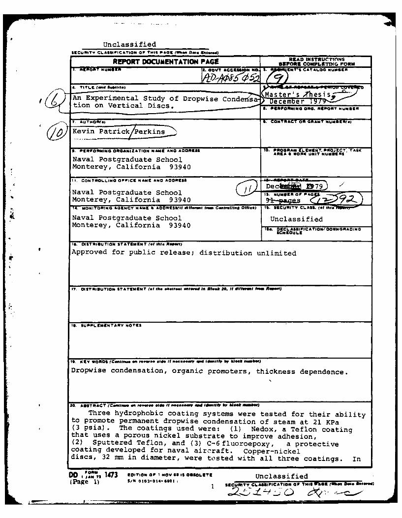
REPORT DOCUMENTATION PAGE READ ZMsTRuc1TFRsI. REPORT NUMBER I&. GOVT AcasmaO ",oJf.W "T*S CATALOG NUMIBQ
4. TITLE (40d Sb~
An Experimental Study of Dropwise Conder'sa- ster'/s T Jhesi"tion on Vertical Discs. 0. PERPORMING Ono. REPORT NUM8ER
7. AkT-OR-) 6. CONTRACT OR GRANT NUMBIER(s)
Kevin Patrick
9. 0ER1PORMING ORG4NIZATION NAME ANO ACOREIS 10. PROGRAM ELIEMENT. PROJECT. TASKAREA A WORK UNIT NUIERNS
Naval Postgraduate SchoolMonterey, California 93940
I1. CONTROLLING OPICE NAME ANO ACORESS
Naval Postgraduate School 0 , ' ....Monterey, California 93940 i- ,e .Z.14. MONI ORING AGoCY NAME h AOORESS,(I l difl f ban. Contrllni O1169) IS. SECURITY CLASS. (of dIs--0Wr,-0
Naval Postgraduate School UnclassifiedMonterey, California 93940 IS& 06CLASSIFICATIONOOWNORAOING
SC EOUL1E
It. OISTRIGUTION STATEMENT (of thle fl nrtj
Approved for public release; distribution unlimited
17. OISTMIUUTION STATEMENT (ef thA. oetet Ntr0d Ifn 8100k It, S difl0erm4 hvm RsP..)
Il. SUPPLEMENTARY NOTES
19. EV WROS (Cipme on rew,*ee olde If noeoorad Idmettr by 61008 M10)
Dropwise condensation, organic promoters, thickness dependence.
20. ANSTRACT (CeRIOmS 40 ,eVerc, Olids it 0e40e4 ld ids" A so b S b u e)Three hydrophobic coating systems were tested for their ability
to promote permanent dropwise condensation of steam at 21 KPa* (3 psia). The coatings used were: (1) Nedox, a Teflon coating
that uses a porous nickel substrate to improve adhesion,(2) Sputtered Teflon, and (3) C-6fluoroepoxy, a protectivecoating developed for naval aircraft. Copper-nickeldiscs, 32 mm in diameter, were tested with all three coatings. In
DD , 1473 EDITION OP NOV65 IS OUSOLETE Unclassified(Page 1) S/N 601 61-6.6 011 S-€:RTy €|,M.,iCATION OF TN*G r ". ,
Unclassified
CteUgIITv CLASIPICS@O 41 0 TWOS P0S9 ~me ftteo ame d.E,
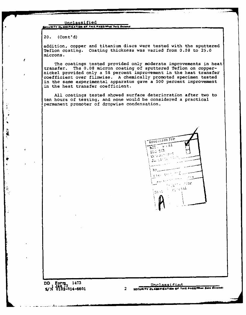
20. (Cont'd)
addition, copper and titanium discs were tested with the sputteredTeflon coating. Coating thickness was varied from 0.08 to 25.0microns.
The coatings tested provided only moderate improvements in heattransfer. The 0.08 micron coating of sputtered Teflon on copper-nickel provided only a 58 percent improvement in the heat transfercoefficient over filmwise. A chemically promoted specimen testedin the same experimental apparatus gave a 500 percent improvementin the heat transfer coefficient.
All coatings tested showed surface deterioration after two toten hours of testing, and none would be considered a practicalpermanent promoter of dropwise condensation.
4
For
DD FarrU3 1473 UncIa-qgi f i ioS1/ MI ) 01446601 2 cuin.,v eghauaa,io ai ol we$ PAges- ate ai"
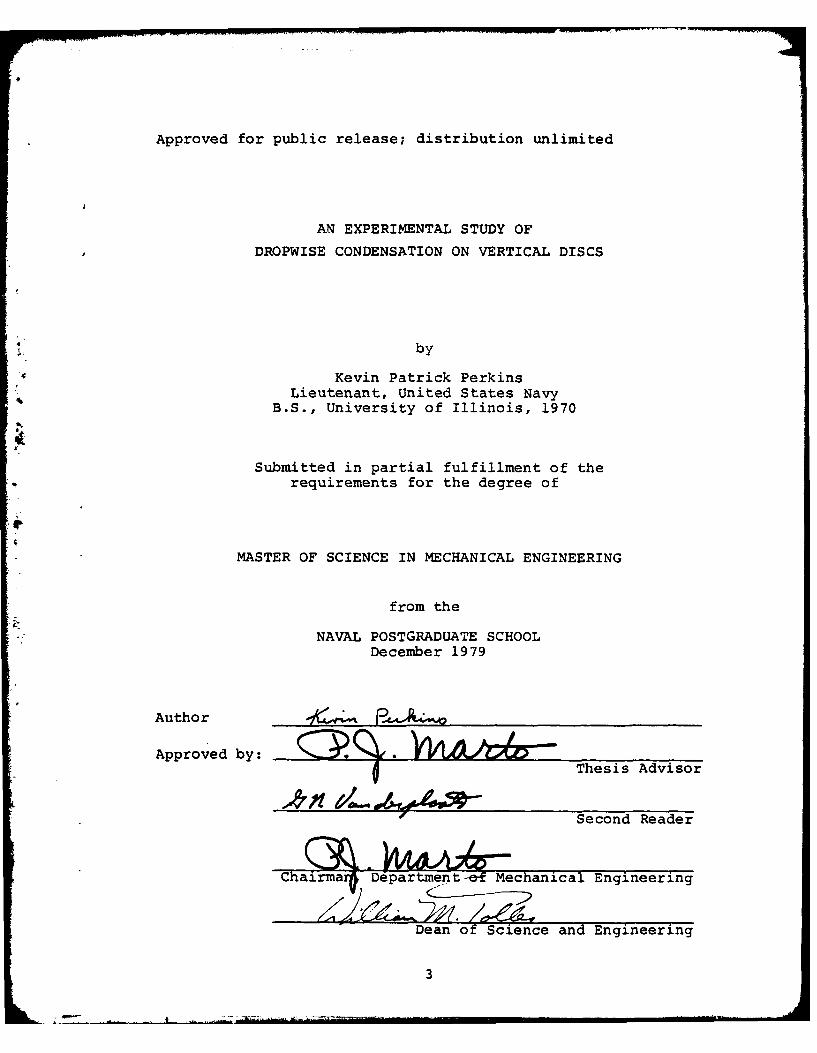
Approved for public release; distribution unlimited
AN EXPERIMENTAL STUDY OF
DROPWISE CONDENSATION ON VERTICAL DISCS
by
.1 Kevin Patrick PerkinsLieutenant, United States Navy
B.S., University of Illinois, 1970
Submitted in partial fulfillment of therequirements for the degree of
MASTER OF SCIENCE IN MECHANICAL ENGINEERING
from the
NAVAL POSTGRADUATE SCHOOLDecember 1979
Author
Approved by:Thesis Advisor
Second Reader
Chairma Departmnt& Mcanical Engineering
Dean of Science and Engineering
3
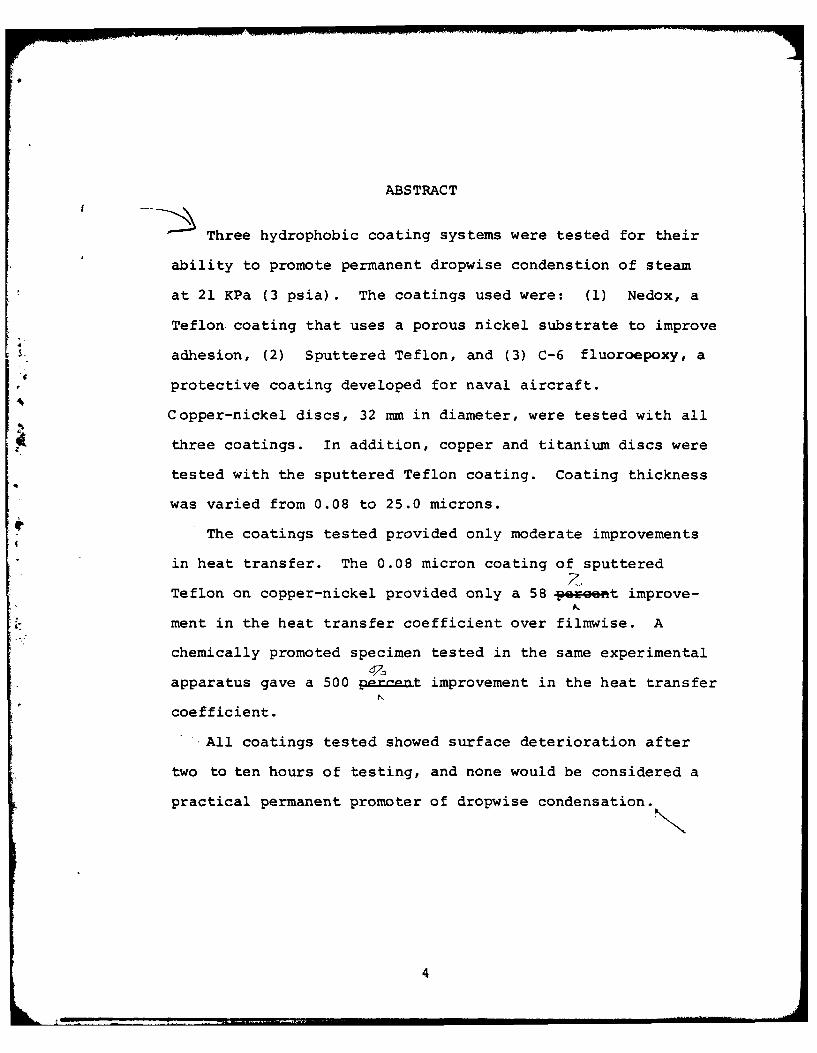
ABSTRACT
Three hydrophobic coating systems were tested for their
ability to promote permanent dropwise condenstion of steam
at 21 KPa (3 psia). The coatings used were: (1) Nedox, a
Teflon coating that uses a porous nickel substrate to improve
adhesion, (2) Sputtered Teflon, and (3) C-6 fluoroepoxy, a
protective coating developed for naval aircraft.
Copper-nickel discs, 32 mm in diameter, were tested with all~three coatings. In addition, copper and titanium discs were
tested with the sputtered Teflon coating. Coating thickness
was varied from 0.08 to 25.0 microns.
The coatings tested provided only moderate improvements
in heat transfer. The 0.08 micron coating of sputtered
Teflon on copper-nickel provided only a 58 poweett improve-
ment in the heat transfer coefficient over filmwise. A
chemically promoted specimen tested in the same experimental
apparatus gave a 500 percent improvement in the heat transfer
coefficient.
All coatings tested showed surface deterioration after
two to ten hours of testing, and none would be considered a
practical permanent promoter of dropwise condensation.
4
TABLE OF CONTENTS
I. INTRODUCTION------------------------------------------- 11
A. BACXGROUND INFORMATION----------------------------- 11B. FILMWISE CONDENSATION------------------------------ 12C. DROPWISE CONDENSATION------------------------------ 12D. FACTORS THAT INFLUENCE DROPWISE CONDENSATION -------13E. PROMOTION OF DROPWISE CONDENSATION -----------------15
1. Noble Metals------------------------------------ 16
2. Organic Promoters------------------------------- 17
4F. PURPOSE OF STUDY----------------------------------- 18
ii. EXPERIMENTAL APPARATUS---------------------------------- 19
A. INTRODUCTION--------------------------------------- 19B. CONDENSING CHAMBER--------------------------------- 20
1. Condenser Test Section------------------------ 202. Specimen Holder-------------------------------- 21
C. SUPPORT SYSTEMS------------------------------------- 22D. INSTRUMENTATION------------------------------------ 22
1. Temperature------------------------------------ 222. Flow Rate--------------------------------------- 233. Pressure--------------------------------------- 23
E. PERMANENT COATINGS---------------------------------- 23
1. C-6 Fluoroepoxy---------------------------------- 242. Nedox--------------------------------------------- 253. Sputtered Teflon---------------------------------426
F. CHEMICALLY PROMOTED SPECIMENS----------------------- 26
G. UNCOATED SPECIMEN------------------------------------ 27
III. EXPERIMENTAL PROCEDURES---------------------------------- 28
A. OPERATING PROCEDURES--------------------------------- 28B. HEAT TRANSFER DATA REDUCTION----------------------- 30
IV. RESULTS AND DISCUSSION--------------------------------- 32
A. INTRODUCTION--------------------------------------- 32
1. Treatment of Data------------------------------ 32
2. Overview of Results---------------------------- 33
Lk 5
B. PERFORMANCE OF COATINGS------------------------------ 34
1. C-6 Fluoroepoxy---------------------------------- 342. Nedox--------------------------------------------- 353. Sputtered Teflon--------------------------------- 36
C. EFFECT OF COATING THICKNESS------------------------- 36
1 . overview----------------------------------------- 362. C-6 Fluoroepoxy---------------------------------- 373. Nedox--------------------------------------------- 374. Sputtered Teflon--------------------------------- 385. Discussion of the Coating Thickness Results---38
*D. EFFECT OF NON-CONDENSABLES-------------------------- 40E. EFFECT OF CONDENSER MATERIAL------------------------ 41F. EFFECT OF SURFACE ROUGHNESS------------------------- 41
V. CONCLUSIONS----------------------------------------------- 43
VI. RECOMMENDATIONS------------------------------------------- 44
VII. TABLES---------------------------------------------------- 45
VIII. FIGURES--------------------------------------------------- 57
APPENDIX A: UNCERTAINTY ANALYSIS----------------------------- 76
APPENDIX B: CALCULATION OF EXPECTED HEAT TRANSFERCOEFFICIENT--------------------------------------- 78
APPENDIX C: SAMPLE CALCULATIONS------------------------------- 80
APPENDIX D: NUSSELT ANALYSIS---------------------------------- 84
BIBLIOGRAPHY---------------------------------------------------- 86
INITIAL DISTRIBUTION LIST-------------------------------------- 89
6
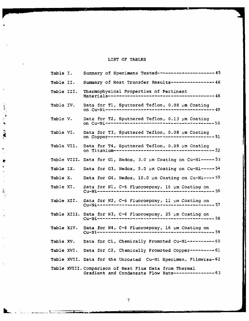
LIST OF TABLES
Table I. Summary of Specimens Tested--------------------- 45
Table II. Summary of Heat Transfer Results ---------------- 46
Table III. Thermophysical Properties of PertinentMaterials --------------------------------------- 48
Table IV. Data for Tl, Sputtered Teflon, 0.08 pm Coatingon Cu-Ni ---------------------------------------- 49
Table V. Data for T2, Sputtered Teflon, 0.13 pm Coatingon Cu-Ni ---------------------------------------- 50
Table VI. Data for T3, Sputtered Teflon, 0.08 pm Coatingon Copper --------------------------------------- 51
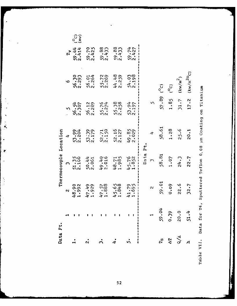
Table VII. Data for T4, Sputtered Teflon, 0.08 pm Coating
on Titanium ------------------------------------- 52
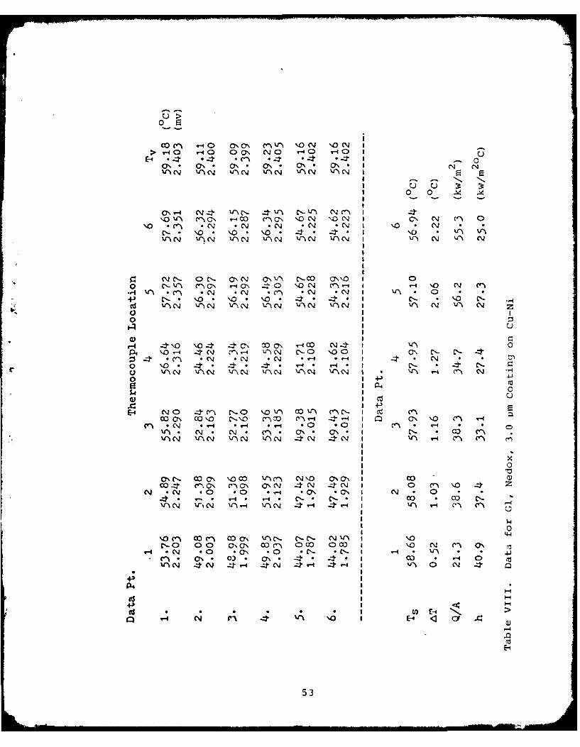
Table VIII. Data for Gl, Nedox, 3.0 vim Coating on Cu-Ni ----- 53
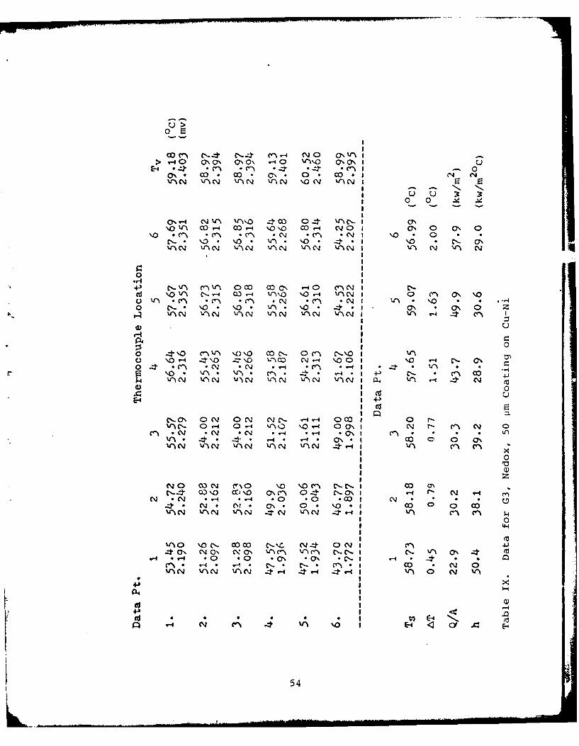
Table IX. Data for G3, Nedox, 5.0 pm Coating on Cu-Ni ----- 54
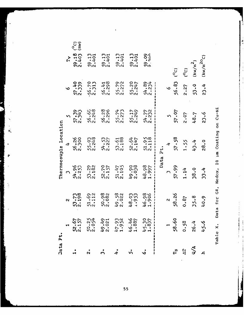
Table X. Data for G4, Nedox, 10.0 Um Coating on Cu-Ni --- 55
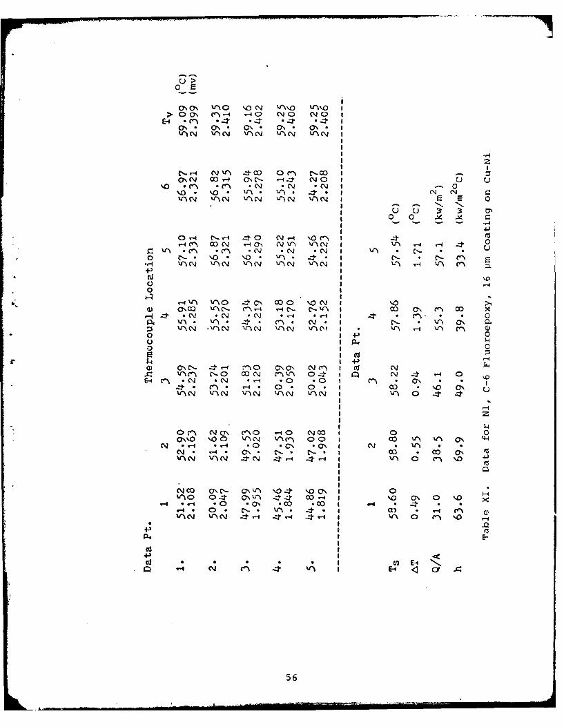
Table XI. Data for Nl, C-6 Fluoroepoxy, 16 um Coating onCu-Ni ------------------------------------------- 56
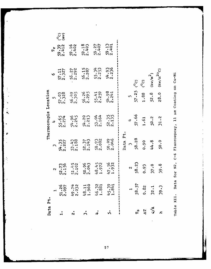
Table XII. Data for N2, C-6 Fluoroepoxy, 11 pm Coating onCu-Ni ------------------------------------------- 57
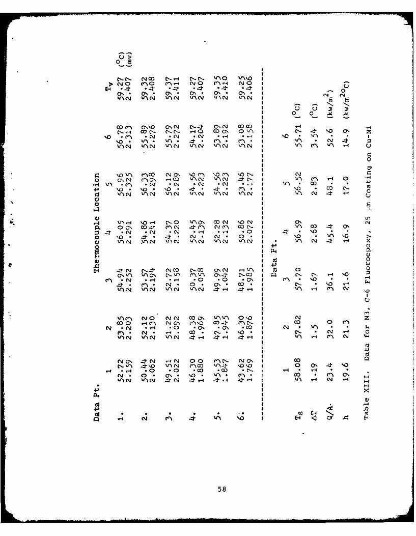
Table XIII. Data for N3, C-6 Fluoroepoxy, 25 im Coating onCu-Ni ------------------------------------------- 58
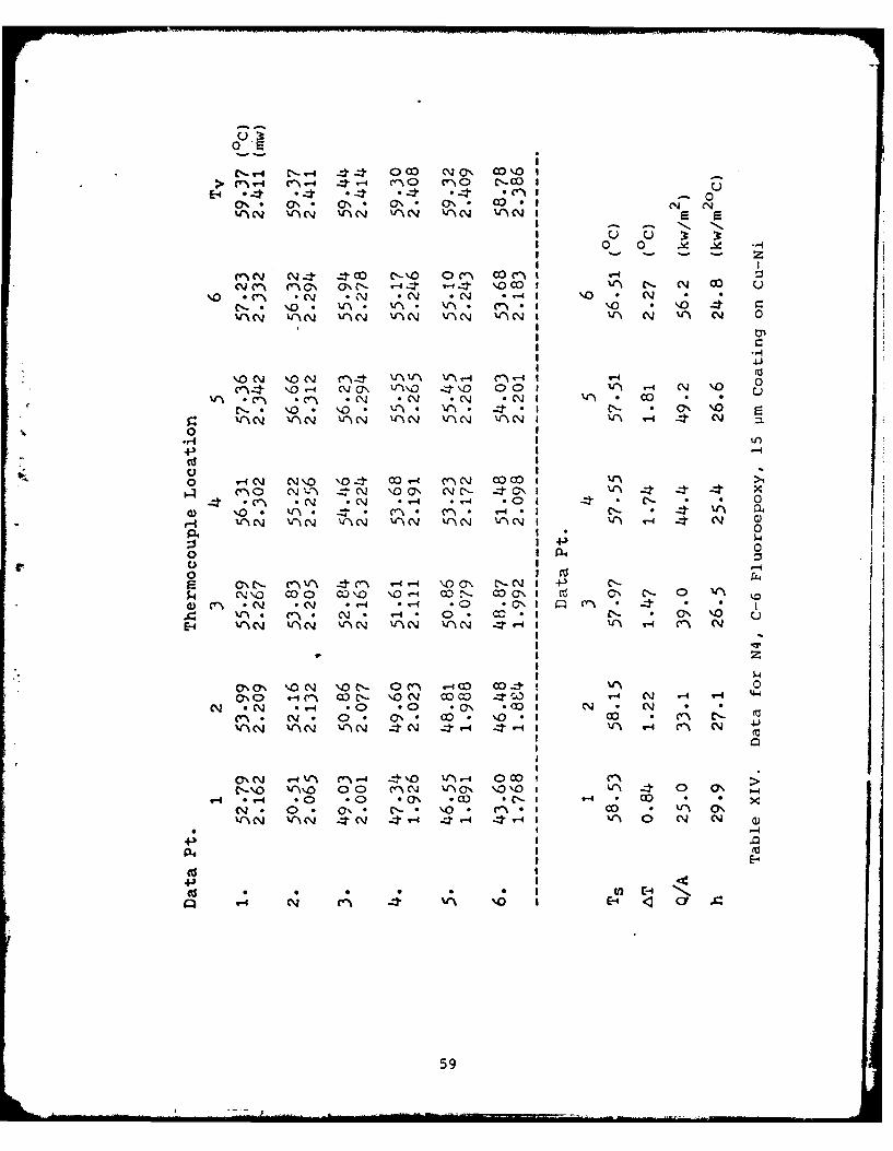
Table XIV. Data for N4, C-6 Fluoroepoxy, 16 vim Coating on
Cu-Ni ------------------------------------------- 59
Table XV. Data for Cl, Chemically Promoted Cu-Ni ---------- 60
Table XVI. Data for C2, Chemically Promoted Copper --------- 61
Table XVII. Data for the Uncoated Cu-Ni Specimen, Filmwise-62
Table XVIII. Comparison of Heat Flux Data from ThermalGradient and Condensate Flow Rate --------------- 63
7

LIST OF FIGURES
Figure 1. Visualization of Heat Flux Near Surface Due toDropwise Condensation --------------------------- 64
Figure 2. Schematic Drawing of Experimental Apparatus ----- 65
Figure 3. Condensing Chamber ------------------------------ 66
Figure 4. Thermocouple Hole Locations and a TypicalThermocouple Hole ------------------------------- 67
Figure 5. Nylon Retainer Ring ----------------------------- 68
Figure 6. Specimen Holder --------------------------------- 69
Figure 7. Typical Thermal Gradient, G4, Nedox ------------- 70
Figure 8. Heat Flux vs. AT for the Uncoated Cu-NiSpecimen, Filmwise Condensation ----------------- 71
Figure 9. Heat Flux vs. AT for the C-6 FluoroepoxyCoating on Cu-Ni Specimens ---------------------- 72
Figure 10. Heat Flux vs. AT for the Nedox Coatings onCu-Ni Specimens --------------------------------- 73
Figure 11. Heat Flux vs. AT for the Sputtered TeflonCoatings on Cu-Ni Specimens --------------------- 74
Figure 12. Coating Thickness vs. Heat TransferCoefficient ---------------------.---------------- 75
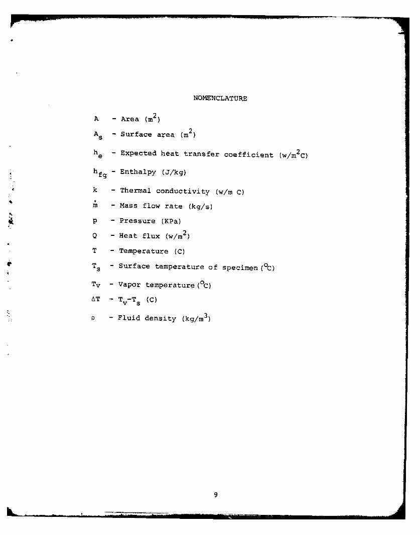
NOMENCLATURE
A - Area (m2)
As - Surface area (m2)
he - Expected heat transfer coefficient (w/m 2C)
Shfg - Enthalpy (J/kg)
k - Thermal conductivity (w/m C)
m - Mass flow rate (kg/s)
p - Pressure (KPa)
Q - Heat flux (w/m2
T - Temperature (C)
T s - Surface temperature of specimen ( C)
Tv - Vapor temperature (0C)
AT - Tv-Ts (C)
: - Fluid density (kg/m3
9

ACKNOWLEDGMENT
The work presented here has been supported by Mr. Charles
Miller, Naval Sea Systems Command (Code 05R).
A special note of appreciation is extended to Ken
Mothersell, Tom Christian, Tom Kellogg and Ron Longueira for
their technical assistance.
I am especially grateful to Professor Paul J. Marto, my
thesis advisor, for his invaluable guidance.
10
I. INTRODUCTION
A. BACKGROUND INFORMATION
During the past twenty years the cost of construction of
a rankine cycle power plant, marine or stationary, has risen
dramatically. These increases in cost have lead to a realiza-
tion of the need for more efficient and smaller boilers and
condensers. The need is even greater in the marine applica-
tion because design is constrained by both cost and size. The
main propulsion plant and auxiliary equipment of modern war-
ships consume twenty to forty percent of the total ship volume.
Any reduction in propulsion plant size will provide a twofold
rbenefit. One, there will be a reduction in the initial cost.
Two, more space will be available for other purposes. The
second is an important long term benefit. It can mean greater
operating range, more weapons capability or perhaps a smaller
ship. In short, it means greater design flexibility.
There has been some reduction in the size of marine pro-
pulsion plants, but most of the effort has been in the area of
boiler design. Boiler operating pressures and temperatures
have been increased, thus reducing size. There have also been
modifications in air flow through the boiler that have improved
efficiency. The marine condenser has remained basically
unchanged for the past thirty years.
Search [] did a feasibility study to determine what im-
provements could be made in the marine condenser. His results
11
indicate that more than thirty percent improvement in heat
transfer could be expected if the condensation was dropwise
vs. filmwise. This was based on a tenfold increase in the
outside heat transfer coefficient, not unreasonable for drop-
wise condensation. A corresponding reduction of thirty percent
in condenser weight and a twenty-three percent reduction in
condenser volume could be expected. Unfortunately dropwise con-
densation is not as stable or well understood as filmwise
condensation.
B. FILMWISE CONDENSATION
Filmwise condensation is the normal mode of condensation
on all condenser materials. A sheet of water forms on the
condenser surface because of the high surface energy of the
condenser materials. Further condensation takes place on the
sheet of water, which introduces an additional resistance to
heat transfer. This is a relatively high resistance, so film-
wise condensation is not strongly affected by lower order
resistances such as fouling of the condenser surface or the
presence of non-condensable gases. It is a stable and pre-
dictable mode of heat transfer.
C. DROPWISE CONDENSATION
Dropwise condensation occurs when, by artificial means
(promoters) the surface energy of the condenser material is
lowered. This causes the water to form on the surface in
droplets; nence the name. The droplets form rapidly, and
fall off, resulting in a dramatic reduction in the resistance
12
to heat transfer. Because of this, dropwise condensation is
very sensitive to other resistances, such as non-condensable
gases and surface fouling.
Two theories have been proposed to explain the dropwise
phenomenon. Jakob [2] believed that a very thin liquid film
formed on the surface, then coalesced, forming drops that then
rolled off. The second theory, developed by Tammam and
Boehme [3] is the nucleation theory. It says that the drops
are formed at nucleation sites on the surface and that the
area between the drops is dry. The nucleation theory is
generally accepted today.
Compared with filmwise condensation, dropwise is far more
difficult to study. The process of drop formation and removal
rfrom the surface is an unsteady and non-uniform phenomenon.
Graham and Aerni [4] described what can be called the life of
a drop. A drop starts at a nucleation site and grows rapidly
by condensation. As the drop grows, it comes in contact with
many other small drops. The drops coalesce, forming larger
drops. When a drop is about 0.1 mm in diameter, direct con-
densation almost stops except in the vicinity of the interface
of the liquid, vapor and condenser surface, where high heat
transfer rates continue. The drop continues to grow, primarily
by coalescence, until it reaches a critical size when surface
tension is overcome by external forces, such as gravity or
vapor shear, and the drop departs from the surface.
D. FACTORS THAT INFLUENCE DROPWISE CONDENSATION
Tanasawa [5] noted twenty-three factors that influence
the heat transfer coefficient of dropwise condensation. Among
13
the most important are: (1) condenser surface roughness,
(2) surface coating or promoter, (3) external forces,
(4) thermal properties of the condenser material, and (5) non-
condensable gases.
The first three factors work together to determine drop
departure size. Drop departure diameter has been shown both
by theory and experiment [5) to be related to the heat transfer
coefficient. Smaller drop departure diameters yield higher
heat transfer coefficients. The ideal condenser would have a
mirror smooth surface with many small nucleation sites. The
promoter would, ideally, be as thin as possible, a mono-
molecular layer thick, and would impart to the condenser
surface a very low surface energy. Also, the external forces
of gravity and vapor shear would act together to remove the
droplets as rapidly as possible.
The effect of the fourth factor, condenser material
thermal properties, is a highly debated subject. Hanneman
and Mikic [6] have proposed a theory that there is an addi-
tional resistance to condensation because of the non-
uniformity of dropwise condensation. They postulate that,
because of the size and spacing of the drops on the surface,
there is a non-uniformity in surface temperature and heat
flux. The large drops, for example, act as insulators against
the heat flux, while the small drops have a great heat flux
through them. Figure 1 illustrates the effect on heat flux
near the surface. The net result of this non-uniformity in
heat flux is an additional resistance to heat transfer known
as the constriction resistance. Low thermal conductivity
14
materials show greater non-uniformity in surface temperature
because they allow less lateral heat transfer near the surface.
As a result they have a higher constriction resistance.
Hanneman and Mikic support this theory with data of their own
and others. Rose [7] represents the opposite view. He believes
the non-uniformities in surface heat flux are rapidly homoge-
nized by the frequent coalescences between drops and that the
effect of a constriction resistance, if present at all, is
small. Rose supports his contention with data from several
experiments. The question remains unresolved.
The fifth factor is the effect of non-condensables. It has
long been known that non-condensables reduce the heat transfer
coefficient of filmwise condensation. The effect of non-
condensables on the heat transfer coefficient of dropwise con-
densation is even greater. Graham [8] showed a reduction of
the heat transfer coefficient of over 1200 percent because of
the presence of non-condensable gases.
The two factors that prevent practical application of
dropwise condensation are the adverse effect of non-condensables
and the lack of a petmanent promoter. The first could be over-
come by employing condenser designs that result in high vapor
velocities, or vapor velocities large enough to remove or sweep
away the gases. The second has yet to be adequately resolved.
E. PROMOTION OF DROPWISE CONDENSATION
The promotion of dropwise condensation can be accomplished
in three ways: (1) by chemically promoting (i.e., wiping) the
surface with a liquid chemical, (2) by injecting hydrophobic
chemicals into the vapor, and (3) by permanently coating the
15
surface with a hydrophobic material. The first method is a
laboratory technique, of little use in naval condensers.
Though it provides excellent dropwise condensation, the pro-
moter washes off in a matter of hours. The second technique
is not acceptable because it introduces impurities into the
boiler feedwater system that could plate out on the boiler
tubes. Thus, the third technique of using permanent promoters
becomes the center of interest for naval steam condensers.
Presently there are two types of permanent coatings that show
4promise as dropwise promoters, noble metals and organic
polymers.
1. Noble Metals
The noble metals offer a great advantage in longevity;
however, there is some question about their non-wetting char-
acteristics. Erb and Thelen [9] have found that gold will
produce good dropwise condensation for more than a year.
Wilkins, Bromley and Read [10], however, reported only film-
wise condensation with a gold plated condenser tube. They
attributed the dropwise condensation to the presence of im-
purities in the gold coating. This debate remains unresolved.
Recently Woodruff and Westwater [11] using precisely controlled
procedures, plated a copper disc with various thicknesses of
gold. They found that a thickness of 0.02 microns produced
filmwise condensation. As the thickness was increased, the
mode of condensation gradually changed to dropwise. They
found that a 2.0 micron coating produced perfect dropwise
condensation. Even if gold is found to be a good permanent
promoter, the cost and availability may not make it practical.
16
Woodruff and Westwater estimated a coating cost of 50 dollars
per square meter. This is just the cost of the gold, and it
is based on gold at 200 dollars per troy ounce.
2. Organic Polymers
The second method of producing permanent dropwise
condensation is to use organic polymers. Tanasawa [5] con-
siders this the most promising approach, especially in light
of the developing coating technologies. Teflon has been used
to promote dropwise condensation since the 1950's. The early
efforts met with limited success. The techniques used to
apply Teflon required thick coatings, and adhesion was often
a problem. Smith [12] obtained only a 10 percent improvement
in the overall heat transfer coefficient using Teflon promoted
copper-nickel tubes. He also reported rapid degradation of
the coating performance. Coxe [13], using a 12.5 micron thick
coating, obtained slightly better results. He had a 22 percent
improvement in the overall heat transfer coefficient, and
reported no degradation of promoter performance in a 100 hour
test. Recently, Manvel [14] used two new coating techniques
to apply teflon to horizontal condenser tubes. Using a
commercial coating, Nedox, which combines a very thin coating
of teflon on a nickel base, Manvel obtained slightly better
results than Coxe or Smith. He obtained a 27 percent improve-
ment in the overall heat transfer coefficient and a 53 percent
improvement in the steam side heat transfer coefficient.
These are not, however, the dramatic improvements that would
be expected from dropwise condensation.
17
Graham [8] found that while a copper disc with a 1.5
micron thick coating of Teflon gave excellent dropwise con-
densation, the heat transfer coefficient was only one third
that of an identical chemically promoted surface. This
drastic reduction can be attributed to the extra resistance
to heat transfer introduced by the low thermal conductivity
of the Teflon coating. He indicated that the solution was to
reduce the thickness of the coating.
The development of new coating technologies has made
Teflon more attractive. Vacuum deposition techniques can now
be used to apply extremely thin coatings of Teflon.
F. PURPOSE OF STUDY
The purpose of this study was to examine the ability of
three coatings to promote permanent dropwise condensation on
90-10 copper-nickel discs. The coatings tested were:
(1) Nedox, a coating system developed by the General Magnaplate
*Corporation, (2) Teflon, applied by a sputtering technique
that permitted very thin coatings, and (3) C-6 fluoroepoxy,
developed by Dr. James Griffith of the Naval Research Laboratory.
Coating thickness was varied in an effort to determine an
optimum thickness for permanence and heat transfer. Addition-
ally, the sputtered Teflon was applied to copper and titanium
specimens to determine the effect of condenser material on the
heat transfer coefficient. Finally, two specimens were polished
P4 to a mirror smooth surface to measure the effect of surface
roughness. One was coated with Nedox, and the other was
coated with C-6 fluoroepoxy.
18
II. EXPERIMENTAL APPARATUS
A. INTRODUCTION
The experiment apparatus was designed and built by Sharp
[ 15]. It consisted of three major components: (1) the con-
densing chamber, (2) the support systems, and (3) the instru-
mentation. Figure 2 shows a schematic of the entire system.
B. CONDENSING CHAMBER
The condensing chamber was constructed using a thick
walled Pyrex glass cross 457.2 mm by 304.8 mm. The chamber
was designed so that boiling and condensation took place in
the same closed chamber. At the bottom of the chamber, five
250 watt immersion heaters were used to boil the water. The
power input to the heaters was controlled by a Powerstat
variable transformer. An auxiliary condenser was installed
in the upper portion of the chamber. This provided for
control of the-steam pressure and steam flow rate past the
specimen.
The condenser test section was mounted on one side of the
cross, and a heated viewport was mounted on the other side.
This arrangement provided an excellent view of the specimen
during the test runs. Mounted inside the chamber was a
small (12.5cc) Teflon cup that was used to collect and measure
the condensate from the specimen. Teflon was used because
of its machinability and relative freedom from outgassing
when hot. The connections for the vacuumn system, manometer,
thermocouples and auxiliary condenser were all made through
19
the top plate. Figure 3 illustrates the details of the
condensing chamber.
1. Condenser Test Section
The condenser test section consisted of two main parts;
the specimen, with its nylon retainer ring, and the specimen
holder. The test specimens were designed so that both heat
flux and surface temperature could be obtained from a knowledge
* of the temperature distribution within the piece. The specimen
holder and retainer ring were designed to ensure one dimensional
heat flow.
The test specimens were solid cylinders 15.24 mm long
and 31.75 mm in diameter. Five thermocouple holes were drilled
radially to a depth of 13.34 mm into each specimen. The holes
4 were equally spaced, 2.54 mm apart, along the length of the
specimen. In an effort to minimize the effect of thermal
distortion induced by the thermocouple holes, the holes were
not lined up but were rotated 72 degrees from each other. In
addition to the five main thermocouples, two thermocouples
were located 2.54 mm from the front surface, one at a radial
depth of 5.08 mm and the other at 15.24 mm. These thermo-
couples were used to determine if there was any heat flux
in the radial direction. All thermocouple holes were 0.57 mm
in diameter. Because accurate placement of the thermocouple
holes was essential to an accurate determination of surface
temperature, two specimens were cut in half and the placement
of four thermocouple holes was checked by using an optical
microscope with a calibrated grid. The maximum deviation
from the specified location was 0.005 nun (.002 in.). To
20
obtain this accuracy, a starter hole, 0.81 mm in diameter and
5.08 mm deep, was used in six of the seven thermocouple holes.
Figure 4 shows details of the specimen and the thermocouple
holes.
Originally, the specimens were pressed into a nylon retainer
ring and then pinned in place with a 1.60 mm diameter drill bit.
Nylon was chosen because of its low thermal conductivity and
relative freedom from outgassing when hot. It was felt that
the pressed fit would provide an adequate seal between the
specimen and retainer ring. However, because of nylon's high
thermal expansion coefficient, the ring expanded when heated
to the operating temperature of 60 0C, and an adequate seal was
not provided. This allowed cooling water to run past the
specimen and into the condensing chamber. The problem was
solved by inserting a 0.127 mm thick piece of stainles, steel
shim stock between the nylon retained ring and the specimen
holder. This provided a positive vacuum seal, yet did not
significantly affect heat transfer. Figure 5 shows the details
of the nylon ring.
2. Specimen Holder
The specimen holder was designed to place the specimen
in the path of the steam flow, and to provide impingement
cooling to the specimen. The specimen holder was constructed
of nylon. It was made in two pieces, the front and rear
chambers. The front chamber held the specimen and provided
the water passage for cooling the specimen. The rear chamber
provided the inlet and outlet cooling water passage. Figure 6
shows details of the specimen holder.
21
C. SUPPORT SYSTEMS
Three support systems were required for the operation of
the condensing chamber: (1) the cooling water system, (2) the
refrigeration/heating system, and (3) the vacuum system.
The cooling water system was used to remove heat from the
test specimen and the auxiliary condenser. It consisted of
a 1/3 horsepower pump, a large reservoir (863.6 mm by 330.2 mmn
* by 304.8 mm) , and a flowmeter. Mounted inside the reservoir
were a refrigeration coil, and two 250 watt immersion heaters.
This arrangement provided for very precise control of cooling
water temperature, and flow to the specimen.
The vacuum system was used to maintain the desired pressure
in the condensing chamber. It also served to vent non-
condensables from the chamber. The vacuum system consisted of
a Duo-seal mechanical vacuum pump, a moisture separator and a
bleed valve that could be used to control the vacuum pressure
in the chamber.
D. INSTRUMENTATION
1. Temperature
The following temperatures were monitored: (1) the
temperature profile in the specimen, (2) the liquid and vapor
temperatures in the condensing chamber, and (3) the cooling
water inlet and outlet temperatures.
In all cases, stainless steel sheathed, copper-
constantan thermocouples were used. The seven thermocouples
used to measure the temperature profile in the specimen were
all 0.508 mm diameter sheathed, with ungrounded junctions.
22

The small size and ungrounded junction acted to minimize the
uncertainty of the hot junction location in the specimen.
All thermocouples were connected to a Hewlett Packard
2010C Data Acquisition System that was used to record all
temperature data. This system was calibrated using a Rosemount
Engineering Company Model 913A variable temperature bath.
Water was the working medium. The temperature in the bath was
measured using a Platinum Resistance Thermometer connected to
a high precision Rosemount commutating bridge model 920A. This
system provided an accuracy of + 0.002 0 C, and was used as the
standard for calibration.
A computer program utilizing the IBM Scientific Sub-
routine INTRPL was used to convert millivolt readings from the
thermocouples to degrees centigrade. The subroutine utilized
a piecewise cubic interpolation scheme through the calibration
points to provide a smooth calibration curve. The calibration
curve accuracy was considered to be + 0.050C.
2. Flow Rate
The flow rate of the cooling water was monitored by a
Fischer and Porter Precision Bore Flowrater, with a maximum
flow rate of 0.70 kg/s.
3. Pressure
Chamber pressure was monitored by using a standard U-
tube mercury manometer calibrated in millimeters.
E. PERMANENT COATINGS
Three types of permanent coatings were used in this study.
Copper-nickel specimens were used with all three. The coatings
23
were: (1) C-6 fluoroepoxy, (2) Nedox, and (3) sputtered
Teflon. The sputtered Teflon was also applied to copper and
titanium specimens. Table I lists nomenclature, nominal or
requested coating thickness, and measured coating thickness
for all specimens used in this study. For the specimens
coated with the C-6 fluoroepoxy, there was a significant
difference between the nominal coating thickness and the
measured coating thickness. This difference was attributed
to the method used to coat the specimens.
1. C-6 Fluoroepoxy
C-6 fluoroepoxy was developed as a protective coating
for naval aircraft by Dr. James Griffith of the Naval Research
Laboratory's Chemistry Division. It is hydrophobic, soil
resistant and inert. Four specimens were coated with C-6
fluoroepoxy. The specimens were coated by dipping them in a
standard solution of C-6 fluoroepoxy with an equivalent amount
of Si-2 silicone amine as the curing agent. The solvent was
Freon TF. The thickness of the coating was increased by
repeated dippings of the specimen in the solution.
Before coating, one of the specimens was polished to
a mirror smooth finish. The remaining three were left with
a machined surface. Three different coating thicknesses were
requested. Table I shows the nominal thickness values and
the values obtained by cutting the specimens in half with a
waffering saw, and examining the edges with a Scanning
Electron Microscope (SEM). All the specimens examined showed
great non-uniformity of coating thickness; for that reason
24
there is a great uncertainty in the coating thickness, approxi-
mately + 5.0 microns.
2. Nedox
Nedox is a commercially available coating technique
developed by the General Magnaplate Corporation of Linden,
New Jersey (GMP). Nedox is a proprietary process of GMP in
which a hard surface nickel alloy is deposited on a copper-
nickel surface. The structure of the deposit is porous, and
a series of proprietary processes enlarge the microstructure
to accept controlled infusion of Teflon. Four specimens
received the Nedox coating. (Specimen G2, with a nominal
coating thickness of 3.0 microns, was not coated with the rest
of the specimens, and was received too late to be adequately
revaluated. It is, therefore, not included in the data.)
Table I shows the nominal and measured coating thicknesses.
Examination of the GMP coatings under the SEM prior
to testing revealed that the Nedox coating was discontinuous
on Specimen Gl. This specimen had the thinnest (3.0 micron
thick) coating and a polished surface below that coating.
The other two specimens,G3 and G4, with nominal 5.0 and 10.0
micron thick coatings, respectively, had continuous coatings.
The coatings were difficult to examine on the SEM because
Teflon is an electrical insulator. This caused a static
charge to build up rapidly on the specimen during scanning
which blurred the image. Specimen G4 tended to blur more
rapidly, indicating the thickness of the Teflon coating was
greater than G3. After testing, the specimens were cut in
half with a waffering saw and examined under the SEM to
25

determine coating thickness. The average coating thickness of
the nickel appeared to be very close to the nominal value,
though there was significant local variance. It was very
difficult to determine the nickel-Teflon interface, and
evaluate the Teflon thickness. Therefore, there is a large
uncertainty in the thickness of the Teflon coating, approxi-
mately ± 0.2 microns.
3. Sputtered Teflon
Teflon was applied by a vacuum deposition sputtering
nrocess at Hohman Plating and Manufacturing Company of Dayton,
Ohio. This resulted in an ultra-thin coating. A total of six
specimens were coated in this manner, two each of copper,
titanium, and copper-nickel. All surfaces were left as
r- machined. Two coating thicknesses were used, 0.08 and 0.13
microns. By its very nature, the sputtering technique provides
precise control of thickness, so the nominal values for thickness
were taken to be accurate. The specimens were examined using
an optical microscope prior to testing, because the SEM was
inoperative when these specimens were received. The coatings
were not continuous. The Teflon appears to have formed at
nucleation sites and then grown outward from them. The
coverage was estimated to be 80 percent complete for the 0.08
micron thickness, and 85 percent complete for the 0.13 micron
thickness.
F. CHEMICALLY PROMOTED SPECIMENS
Two chemically promoted specimens were used in this experi-
ment. They were polished so that they had approximately the
26
same surface smoothness as the specimens with permanent
coatings. The promoter used was n-octadecyl mercaptan in
octanoic acid. It was applied to the surface with a cotton
swab and the surface was rinsed with distilled water. The
specimen was tested immediately after promoter application.
G. UNCOATED SPECIMEN
To provide a reference or standard to be used to measure
the heat transfer enhancement, one specimen was not coated,
but left as machined. This specimen was washed with an in-
dustrial detergent and a solution that consisted of equal
parts of sodium hydroxide and ethyl alcohol. The specimen
was then completely rinsed with distilled water. This proce-
dure ensured filmwise condensation on the surface.
27
III. EXPERIMENTAL PROCEDURES
A. OPERATING PROCEDURES
The following procedures were used to startup and opera-
tion of the experimental apparatus.
1. Approximately 24 hours prior to an experimental run,
the data acquisition system and electronic ice point were
turned on.
2. The condensing chamber was filled with distilled
water to a level of five centimeters above the immersion
heaters.
3. The specimen was mounted in the specimen holder; the
thermocouples were inserted and secured in place with a nylon
strap, and the specimen holder was mounted in the chamber.
Vacuum was drawn down to 100 mm mercury, the isolation valves
closed and the vacuum pump secured. The mercury manometer
was checked after a 30 minute period. Vacuum was considered
satisfactory if a one millimeter or less drop in pressure
was observed.
4. The low pressure air supply and heating element to
the observation port were turned on.
5. The cooling water and refrigeration systems were
activated. The refrigeration system was left on until the
water in the reservoir was approximately seven degrees
centigrade. The cooling water to the specimen was turned
on full flow.
28

6. The immersion heaters In the chamber were turned on
and the power set to 70 percent, 900 watts.
7. When the water temperature reached sixty degrees
centigrade, the vacuum system was activated. On the first
set of trial runs, vacuum pressure in the charrber was controlled
using the bleed valve located between the moisture separator
and the vacuum pump. It is believed that this procedure
allowed air to be sucked back through the moisture separator
into the condenser chamber. After some experimentation, it was
found that the best way to control vacuum and eliminate non-
condensables was to secure the auxiliary condenser and bleed
valve. Pressure was then controlled solely with the Powerstat
regulator to the immersion heaters. It was found that during
steady state operation a Powerstat setting of 60 percent plus
or minus 4 percent would maintain pressure and temperature
within the limits required.
8. once an equilibrium state had been reached, thermocouple
voltages were checked and recorded. If it was the first run
for a coating or specimen material, the rate of condensate
produced was measured. This was done by measuring the time
required to fill the 12.5 cc Teflon cup. It was done to
verify the values of thermal conductivity used for the calcu-
lation of heat flux by Fourier's Law. It was originally
_ntended to measure the condensate flow rate for each specimen
tested. The system worked fine during trial runs when the
bypass valve was used to control pressure. The powerstat
setting required to maintain temperature resulted in a low
29
boiling rate. With the bypass closed, as it was for all experi-
mental runs, the high power setting and boiling rate would
cause water from the boiling section of the chamber to occa-
sionally splash into the Teflon cup, thus confounding the
measurement. As a result, it took constant observation of the
specimen and condensation cup to get a good measurement of
condensate flow rate. Anytime water splashed into the cup,
the run would be stopped and restarted. This increased the
time to get a single data point to an unreasonable period.
For this reason it was decided to measure the condensate flow
rate on selected specimens only.
The heat flux was varied by increasing the cooling water
temperature so the temperature difference (T v - T s) increased
by approximately 0.5 0C for each data point. The (T v- T S)
value was approximated by monitoring the voltages at the first
and second thermocouple positions and calculating a rough
slope to obtain the approximate T .At the lower heat flux% 5
ranges, the cooling water flow rate was also used to vary heat
flux.
B. HEAT TRANSFER DATA REDUCTION
Both heat flux and surface temperature were determined
using the temperature gradient in the specimen. The heat
flux was determined using the one dimensional Fourier equation
Q -k AA AX
The surface temperature was obtained by extrapolating
the temperature distribution inside the specimen to the
30
surface. The temperature gradients were linear and the method
of least squares was used to provide the best fit line through
the thermocouple data. Figure 7 shows the results of a typical
run. As a check, the heat flux was also obtained by collecting
and measuring the rate of condensate flow for selected speci-
ments. The values obtained for heat flux agreed within 22 per-
cent. Using the values for heat flux, surface temperature and
vapor temperature, the heat transfer coefficient was obtained
using Newton's Law of Cooling.
QAtAh=T -
Tv T s
31
I . ....... ..... .. ... . .. ... .. ...... ... ... ........ ..
IV. RESULTS AND DISCUSSION
A. INTRODUCTION
1. Treatment of Data
The technique of measuring the temperature gradient
in a block and extrapolating the results to the surface was
chosen because it was thought to provide the most accurate
measure of the average surface temperature available. Even
so, the uncertainties associated with the data were signifi-
cant. The uncertainty for a typical data point was + 0.25 C
for the thermal potential (T v - T s), and + 2.2 kw/m 2in heat
flux. This gives an uncertainty in the heat transfer co-
efficient of + 4.0 kw/m 20C, or about 13 percent. Appendix A
shows the methods used to calculate the uncertainties, and
the range of values obtained. The results show the effect of
these large uncertainties. The data points were scattered
and several different curves could be fit to each set of data
points. Past studies [8] have shown that for (T v- T S)
greater than 0.3 0C, heat flux vs. (T v - T s) data for dropwise
condensation can be treated as linear. For this reason, and
to treat the data in an unbiased manner, a least squares
straight line was fit through each set of data points.
The chemically promoted specimens transferred heat so
well that the ability of the cooling water system to remove
it became the limiting resistance in the system. In this
situation the values of (T v - T s) obtained varied from 0.52
32
to 0.63 0 C for the copper-nickel specimen, which corresponded
to a heat flux of about 80 kw/m2 . Therefore, the heat transfer
coefficients for the five data points were averaged to obtain
a value of 138 kw/m 2C. This value was used for comparison
with other data. All comparisons between data for permanent
coatings were made based on a (Tv - T s ) of 2 C, which corre-
2sponded to a heat flux of about 80 kw/m2 . The comparisons
between data for the uncoated specimen and all other specimens
were also made based on a (Tv - Ts ) of 20 C. This corresponded
to a heat flux of 45 kw/m 2 for the uncoated specimen. If the
2comparison had been made at a heat flux of 80 kw/m, the
resulting values for h/hun (h/hun is the ratio of the heat
transfer coefficients for the test specimen vs. the uncoated
specimen) would have been 20 percent higher.
2. Overview of Results
Table II shows the specimens tested with their physical
characteristics and selected heat transfer data. The results
show good agreement with existing data. The heat transfer
coefficient for the chemically promoted copper-nickel specimen
was 138 kw/m2oC. The heat transfer coefficient for a similarly
promoted copper specimen was 143 kw/m2oC. These values are
typical of dropwise condensation at this reduced pressure [8],
and are six times the value obtained for the uncoated specimen.
The uncoated specimen exhibited filmwise condensation and the
heat transfer coefficient showed good agreement with one cal-
culated using a Nusselt Analysis: 22.5 kw/m 2C, for the
uncoated specimen vs. 20.8 kw/m 2C from the Nusselt Analysis.
33

Details of the Nusselt Analysis are shown in Appendix C.
Figure 8 shows the plot of Q vs. (Tv - T s ) data for the un-
coated specimen.
As mentioned previously, Manvel [14] used the same
permanent coatings that were tested in this experiment on
horizontal tubes at the same pressure and temperature. A
direct comparison of data is not possible because of differences
in geometry. However, for comparable thicknesses, there was
good aoreement in the percentage improvement of the heat
transfer coefficient for coated vs. uncoated specimens. For
example, for a specimen with a 0.08 micron thick sputtered
Teflon coating, Manvel obtained a 45 percent improvement over
an uncoated tube. This study, for the same coating thickness,
showed a 58 percent improvement.
B. PERFORMANCE OF PERMANENT COATINGS
1. C-6 Fluoroepoxy
The quality of dropwise condensation prodiced by C-61
fluoroepoxy was fair to poor. All of the specimens tested
showed degradation of performance in promoting dropwise con-
densation after two to three hours. The thicker coatings
showed physical failure of the surface by cracking. It is
believed that this was caused by the difference in thermal
expansion between the copper-nickel disc and the coating.
1 This qualitative comparison is based upon the visual be-havior of the dropwise process, including the nucleation ofmicrodrops, their coalescence, and large drop departureconditions.
34
Figure 9 shows the plots of Q vs. (TV - Ts ) for the four speci-
mens. Because of the large uncertainty in the data, and to
treat all data from the permanent coatings in a consistent
manner, it was decided to fit straight lines to the data points
for each specimen. In some cases (i.e., N4) this does not
provide the best fit curve for the data. The difference
between the linear fit and the best fit is in all cases less
than the uncertainty in the data.
2. Nedox
The Nedox coated specimens gave the best quality drop-
wise condensation. The specimens with the continuous coatings
(G3 and G4) gave dropwise condensation as good as the chemically
promoted specimens. The specimen with the thinnest and dis-
continuous coating showed good quality dropwise. Overall, they
displayed only moderate increases in the heat transfer coeffi-
cient over the filmwise specimen. The Nedox specimens showed
no reduction in their ability to promote dropwise condensation
during runs of up to ten hours in length. They did, however,
show some physical deterioration of the surface. Small pieces
of Teflon coating were washed off all the specimens. This
left the coating with a discontinuous appearance. Some Teflon
appeared to have remained stuck in the porouf surface of the
nickel. There was no evidence of failure of the nickel sub-
coating. This could explain why the specimens showed no
deterioration on dropwise performance, in spite of partial
failure of the Teflon coating. Figure 10 shows the plots of
Q vs. (TV - Ts ) for the Nedox coatings.
35

3. Sputtered Teflon
Initially, the sputtered Teflon surfaces gave very good
dropwise condensation, but not quite as good as the Nedox coated
specimens. The quality of dropwise condensation began to dete-
riorate within two hours of operation. Several small patches of
filmwise condensation appeared. The drop growth and coalesence
was also slightly slower than the Nedox coated specimens. The
heat transfer coefficients for the sputtered Teflon coatings
were the highest recorded for the permanent promoters, but were
still low for dropwise condensation. After four hours of opera-
&tion, the surfaces showed signs of physical deterioration. The
surface had dulled and small patches of Teflon had peeled away.
Figure 11 shows the plots of Q vs. (Tv - T s ) for the two sputtered
Teflon coatings on Cu-Ni.
C. EFFECT OF COATING THICKNESS
1. Overview
The great advantage of chemical promoters, like n-octadecyl
mercaptan in octanoic acid, is that they are only a monomolecular
layer thick. Therefore, they do not induce a significant additional
resistance to heat flux due to conduction through their thickness.
The permanent promoters used in this experiment, Teflon and C-6
fluoroepoxy both have low thermal conductivities. Even though the
coatings were thin by normal measure, ranging from 0.08 to 25.0
microns, the conduction resistance was significant, because of
their low thermal conductivities.
One way to predict the increased resistance through the
specimen was to assume the heat transfer coefficient for the
chemically promoted copper-nickel specimen represented a value
which could be used for a condensation resistance. This con-
densation resistance could then be added in series with the
36

conduction resistance of the permanent promoter to give an
expected heat transfer coefficient. Appendix B shows the
details of this calculation for a Teflon coated specimen.
Figure 12 shows the results of this calculation graphically,
with the expected heat transfer coefficient plotted as a
function of coating thickness. The experimental results for
the sputtered Teflon and Nedox coated specimens are also
plotted in Figure 12.
2. C-6 Fluoroepoxy
For the machined specimens, the heat transfer coeffi-
cient increased as the coating thickness was reduced. The
specimen with the 25 micron coating showed a reduction in the
heat transfer coefficient when compared with the results of
the uncoated specimen. The other two specimens showed only
modest improvements in the heat transfer coefficient compared
with filmwise. The uncertainty in coating thickness, and
thermal conductivity, as well as the poor quality of dropwise
condensation exhibited make the calculation of an expected
heat transfer curve like that of Figure 12 impractical.
3. Nedox
The Nedox specimens with complete coatings (G3 and G4)
gave excellent dropwise condensation. Specimen GI, which
had a discontinuous coating gave good quality dropwise. Yet
Gl and G3 showed only 10 and 20 percent improvements, respec-
tively, in heat transfer coefficients over the uncoated speci-
men. Specimen G4 showed almost no improvement at all. If
the additional resistances were due solely to one dimensicnal
conduction through the Teflon layer, 0.2 to 0.6 microns thick,
37
an increase of over 300 percent would have been expected.
Nedox had the additional conductive resistance through 3.0
to 10.0 microns of porous nickel. This is a difficult resis-
tance to quantify. Pure nickel has a high thermal conductivity,
90 w/m 0C. The effective conductivity of the porous nickel,
however, is unknown, and is probably different. It is believed
that the resistance induced by the nickel coating was small
compared with that induced by the Teflon coating. Also, the
Teflon, nickel, and copper-nickel, all appeared to be well
bonded, so contact resistance was considered to be negligible.
4. Sputtered Teflon
The sputtered Teflon was applied in ultra-thin coatings,
0.08 and 0.13 microns. As would be expected, these thinner
coatings gave greater improvements in heat transfer than the
thicker Nedox coatings. Thus, 58 and 47 percent improvements,
respectively, in the heat transfer coefficient, were measured
for the coated surfaces vs. the uncoated surface. Once again,
the results were much lower than were predicted by the one
dimensional conduction analysis.
5. Discussion of Coating Thickness Results
The heat transfer coefficient was found to increase
with decreasing coating thickness. Even when the coating was
discontinuous and the quality of dropwise condensation had
deteriorated, an increase in heat transfer was still shown.
There is probably a point (0.01 p~m) where the coating becomes
so discontinuous that it can no longer support dropwise con-
densation, and the heat transfer coefficient will start to
decrease.
38
The data was surprising because the results were so
much lower than expected. The one dimensional analysis used
to generate the expected heat transfer curve was obviously
not adequate to explain the experimental results. Three possi-
ble explanations of the results are presented here:
a. The discontinuous coatings gave dropwise condensa-
tion that was of slightly poorer quality than the chemically
promoted surfaces. This could account for part of the differ-
ence between the experimental and expected results, but it is
not considered adequate to explain the total difference.
b. The two specimens with continuous coatings (G3 and
G4) both gave dropwise condensation as good as the chemically
promoted specimens, yet they also showed a significantly lower
heat transfer coefficient than expected. The porous nickel
coating may have induced a significant resistance, but it does
not seem probable.
c. It is known that Teflon will outgas to a very small
degree when subjected to a vacuum. Even small quantities of
non-condensables have been shown to significantly reduc.--the
heat transfer coefficient of dropwise condensation [16]. It
is possible that the condensing surface itself was acting as
a source of non-condensables. The condensing vapor would
tend to trap the gases close to the surface because the flow
of the vapor is into the specimen. It is felt that this is
probably the main cause of the difference between the expected
and experimental values in heat transfer coefficient.
39
D. EFFECT OF NON-CONDENSABLES
Previous experimenters have shown non-condensable gases
to have a de.7astatinj effect on the heat transfer during
dropwise condensaticn. This experiment was no exception.
The original experimental p-ocedure ased a bleed valve
installed betwe-n the m ztu-,- 'eparatcr and vacuum pump to
contrc oressure in the chamber. Though this procedure
allowed for ver, crecise control of pressure, it also let
air back into the c.,ndenser chamber. This caused a reduction
in the heat transfer coefficient from 30 kw/m 2oC to 8 k /m2o,
The thermal gradient within the specimn for the case with
air present is not linear. It is thought that the reason for
this non-linearity is that the air drawn to the condensi:ic
surface builds up, effectively insulating the condensing
surface until blown away by a blast of steam from the boiler
section. Visual observation of the specimen during dropw.se
condensation supports this theory. The dropwise condensation
would periodically slow and almost stop; then it would start
with what appeared to be a wave of steam over it.
Morgan [17] used a brush recorder to monitor the surface
temperature of a specimen with dropwise condensation in the
presence of non-condensables. He found that the surface
temperature dropped 40C in a period of 2 seconds, and then
rose 4 0 C in the same period. This is the kind of temperature
drop that would be expected from the accumulation of signifi-
cant non-condensables on the surface, and the same kind of
40
a temperature variation that would give the results found in
this experiment.
E. EFFECT OF CONDENSER MATERIAL
There was virtually no difference between the data for
the copper and copper-nickel specimens. The chemically pro-
moted copper specimen had a heat transfer coefficient of
143 kw/m 2C. The similarly promoted copper-nickel specimen
had a heat transfer coefficient of 138 kw/m2oC. The copper
and copper-nickel specimens with the 0.08 wm sputtered Teflon
coatings had heat transfer coefficients of 36.5 and 35.5 kw/m2 C
respectively. The Titanium specimen with the 0.08 urm sputtered
Teflon coating had a heat transfer coefficient of 15.8 kw/m2oC,
which is significantly less than the values for the copper or
copper-nickel.
F. EFFECT OF SURFACE ROUGHNESS
It was originally intended to determine the effect of surface
roughness on the heat transfer coefficient. It was thought
that having a smooth surface below the coating would tend to
make the coating surface smoother. It was found that the Nedox
and C-6 fluoroepoxy coatings were thick enough to smooth out
any machining marks. The smooth and machined surfaces once
coated had almost the same surface characteristics. Specimen
Ni, with a 15 Wm thick coating of C-6 fluoroepoxy on a smooth
surface gave slightly better performance than specimen N2,
which had a 11 pm thick coating of C-6 fluoroepoxy. However,
in light of the uncertainty in the heat transfer coefficient,
and the uncertainty in the coating thickness, this difference
41
is not considered significant, and no conclusions can be drawn
from this data on the effect of surface roughness on the heat
transfer coefficient in dropwise condensation.
ir
.4
42
V. CONCLUSIONS
1. The organic polymers tested would not be acceptable perma-
nent promoters of dropwise condensation. They only showed
moderate improvements in heat transfer, and all showed signs
of physical deterioration after very short operating periods.
2. The heat transfer coefficient was found to be a weak
function of coating thickness. The increases were only moderate,
ranging from-20 to 58 percent for the copper-nickel specimens.
As coating thickness decreased, the difference between expected
values and experimental values increased.
3. There is no significant change in the heat transfer co-
r efficient between copper and copper-nickel. Titanium, however,
does show a significant reduction in heat transfer coefficient
compared to copper or copper-nickel.
4. The chemical promoter gave heat transfer coefficients five
to six times those of the permanent coatings.
5. The presence of non-condensable gases causes a significant
reduction in the heat transfer coefficient for dropwise con-
densation.
43
VI. RECOMMENDATIONS
1. Continue testing NRL fluoroepoxy coatings. It is believed
that the fluoroepoxy may be modified to improve its physical
characteristics for dropwise condensation [18]. It can be
made more hydrophobic, or can be given higher thermal conduc-
tivity. Thinner coatings could also be used.
2. Explore the possibility that other permanent nonwetting
coatings may be commercially available, both organic and
metallic.
3. Conduct further tests with sputtered Teflon to obtain an
ultra-thin continuous coating that will give better quality
dropwise condensation.
4. Conduct analytical and experimental studies of outgassing
of Teflon coated surfaces.
5. Build another experimental apparatus modeled after Graham
[8]. The existing apparatus had several limitations. There
was no way to measure vapor velocity past the specimen. The
large nylon specimen holder, as well as the Teflon cup,
probably induced non-condensables into the condensing chamber.
Also, because of limitations of the cooling water system, the
maximum heat flux through the specimen was around 80 kw/m 2C.
This was not adequate.
44
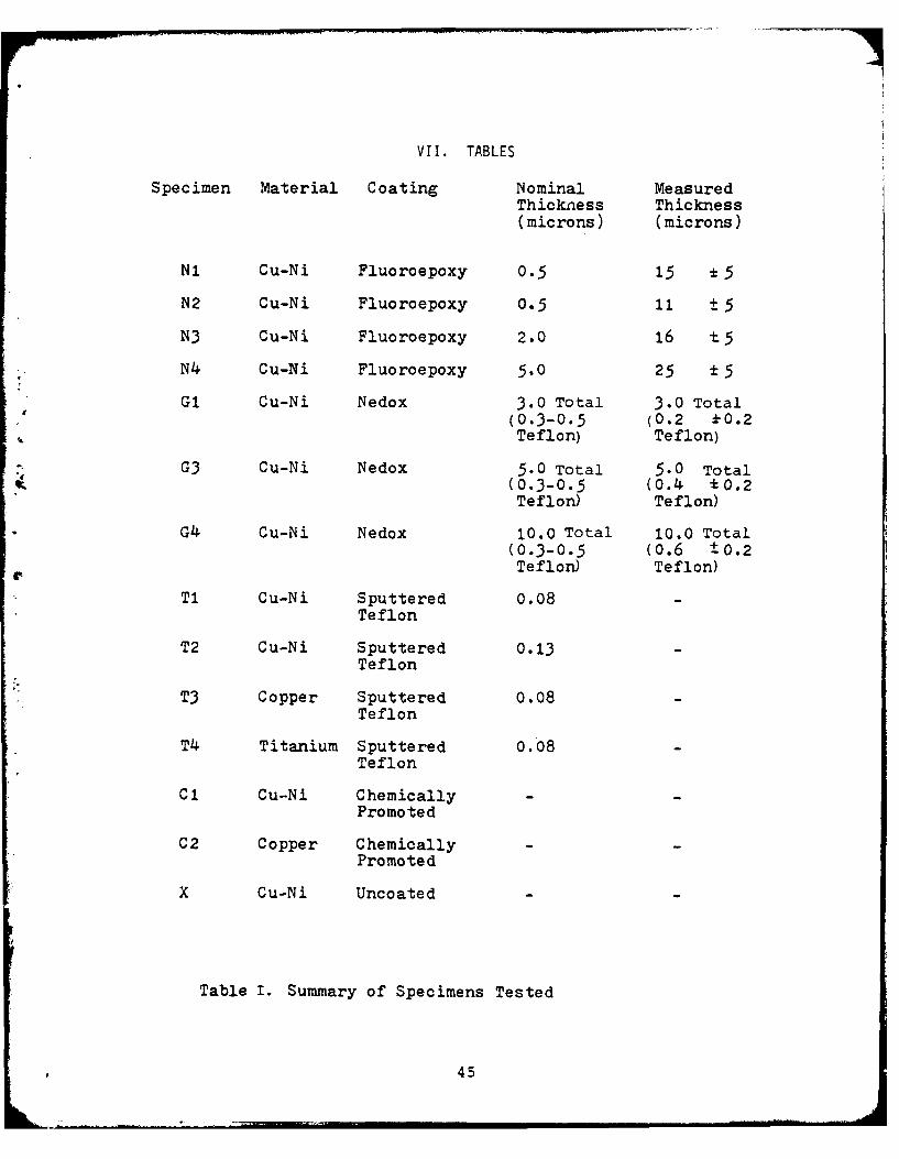
VII. TABLES
Specimen Material Coating Nominal MeasuredThickness Thickness(microns) (microns)
N1 Cu-Ni Fluoroepoxy 0.5 15 *5
N2 Cu-Ni Fluoroepoxy 0.5 11 t 5
N3 Cu-Ni Fluoroepoxy 2.0 16 t5
N4 Cu-Ni Fluoroepoxy 5.0 25 15
G1 Cu-Ni Nedox 3.0 Total 3.0 Total(0.3-0.5 (0.2 A0.2Teflon) Teflon)
G3 Cu-Ni Nedox 5.0 Total 5.0 Total(0.3-0.5 0.4 *0.2Teflon) Teflon)
G4 Cu-Ni Nedox 10.0 Total 10.0 Total(0.3-0.5 (0.6 +0.2Teflon) Teflon)
T1 Cu-Ni Sputtered 0.08Teflon
T2 Cu-Ni Sputtered 0.13Teflon
T3 Copper Sputtered 0.08Teflon
T4 Titanium Sputtered 0.08Teflon
C1 Cu-Ni ChemicallyPromoted
C2 Copper ChemicallyPromoted
X Cu-Ni Uncoated
Table I. Summary of Specimens Tested
45
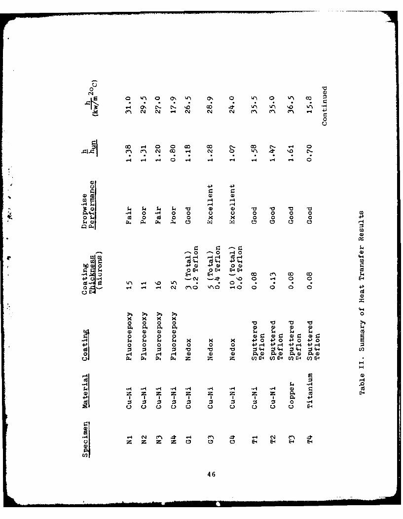
Z3V0
o v** 0 ON V ') ( 0 CC)0
Ad N N '-4 N N N 41 J ~ ~ -
0u
00 V4 0 0 00 00 c-_ 0 0- '-
14 14 C; 0 - H 4 4 -4 4 0
to4 r-. ..r '- N 0-4 0 '
3:0C SiM 4) 4) V V V V
42 S4- 4 0 *r4 0 0 Q. U) 0 0 0 0 ca05 41 Cd 0 cd 0 0 x x 0 0 0 0 +.)
Cl aq
-- - 0 r-4o 0)
W 1 JcUC .6.7 4 -S0 (02go54 0 O-S0 -4 E-4 E-4 C
4t Z)E-4 E-4 00 n 00-
00 k+;)-4- N \- 0 0 V-4 0 0E-
cj" rqV4 Q * 0 * . * . .0- C N n~ \ 4 0 0' 004CQ CU
0
0 0 0 0 5d0 0) 0 0 54 54 54 4 Cd0 0 0 0 4) 4 0~ (1 r 0 rk4 $4 k4 $4 x x x 4)04-l04+) 0+) 020 0 0 0 0 0 0 IJ 4 I4)v-4 4-)r-4 +3 -
Cd :5 :s 0 V V V 344 044 :344 : -0 ~ ~ ~ ~ r- 0- rI r 4 (Dpq Q)P4 0)0 a)O 040
Q, r14 FL4 rF4 P4 z E- OE4E - )E
CU z q' -4
04 .- 4
q-4 *d 4 n.* V- 4 n- C\) *.- --t ~C
m, z, C E-1 E-4 E-0 E4
46

N
4) )
Cd
4~ ~ C)4 S
) 0) 4-
C) 4 0 4)0
.4E-4
UU
I~U
47
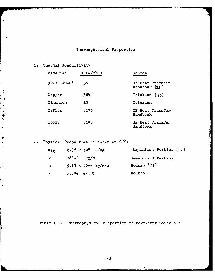
Thermophysical Properties
1. Thermal Conductivity
Material k (w/m°C) Source
90-10 Cu-Ni 56 GE Heat Transfer
Handbook [22]
Copper 384 Tolukian [ 23]
Titanium 20 TolukianNTeflon .170 GE Heat Transfer
Handbook
Epoxy .198 GE Heat TransferHandbook
2. Physical Properties of Water at 60'C
hfg 2.36 x 10⁶ J/kg Reynolds & Perkins [25]
983.2 kg/m Reynolds & Perkins
5.13 x 10- 4 kg/m's Holman [24]
k 0.654 w/m*1C Holman
Table III. Thermophysical Properties of Pertinent Materials
48

u >0 ~
moO cO'.0 N ON n 'I 0-4 c'- OD I C1 N
>* VI CV -it .4 n4 . -t q \ N V)N
'\ N '\ N '% 'AN 'A Cj N ')N CV 0 0 1w
% 0 0'\ N1 N.U'A NO0 N'\~ 0\ 4 V-4 c--- I \0 . 00 * * uc n N CV *\\ 0 N V' *NCj -*N CA .- -I (
\0 .n '.O 'Aj . 'A . 4. 4.g 0~ )r -c
C- - 0 -I - V'V- q W\Cj V\N V%(4 V\N V Cl I 4-i
4 IJ
M-4 n 0\ C C- 4 \0 .- 4 A n~- 'A * .\0 u'A *C' *N *N *Nj *N *Nj N *% .O N\ - .
CN \.0 'A - V) '* 4* '\ V4 \.0 E* '%ANl V 'AN '\N 'tm 'AN C1 V\ (~ U\N 1 I
0
I';\ ON \ la\ C \ -0 "L- I C-
'00' E' 001%C NO'\\ N'.tC L\O i C7\ a\ a,4 ~ *N 'M4 .-q4 . 4 .- .0 1 -t 4 -
V . n '. N~j. Nj. -4. 0. - N * O 0o'O 0AN 'A N 'AN~ U" (%N '\N 'AN \ I 'A q-4 'AN C% _q
0 4A'
4* Em4
0 \01- n \0.,0 C'. C O eNC- N eN c 1NNjC~ N ON \.0 c 'OCO N 1 0 4 1cu
(n~ 'N .0 00 .0 .0' all - 7 4) 441 .y.4 C\ 0 CO N'l--I CU Cn- 0 'D OD CO
r-4 U"*MV\ 4 V 4 N - 4 - -P4 i-4 'A 4 '
* 4N '0 0. W-4N 0'.ONO 00 N-4\4 0' 00C\ V-'\ NN NVl NO'. CC\I -
4) C\J *-4 *. .0'% C) 0'C) . CO *C'4N.C 0,% - 00 eA C- . 4 N- N\ '\ 1-4
E4 %'%('.J 4-* r4 -w 4,4 4,- 4 -4 I N~ o 0 * 0ID o W-4 C'-
A.4 'A 4I 4-
'A. -. %0 0\ (n~- N-4 'NC% Ocr I
r 0 '0 'A\ . 4. N' * 0% .1- 0*0 V N 0 0 .
V' CM r 4 CO 'n40
+; C)
CU -4
.d w 1 E-4 (a- 4 A~ .4 %A '0 E-4 E-4 .
49

o rz
V-4 C%- e'IQ c-CO C- co '% -- co( n 0>. V4 V'%-4 C.- C\j C1% -4 V.C\'-4 v-4 0 N ~ '
-4 U*.- .4.:t.- .~- .
%1-%Cq. V"\ (14 Ur-\JN V\ VA'\~ .Cc\j V'\ C' 10 0a .
* NC% \' 0 N mO
0C 0'.'- 0~t V') COO -! w0 1\ I \.0 * \ zedo'. C .- co C-\~ 00 1'r 11.0 -t 4 ~ N
NO *e\ *j .N C *N *j *-V I V"\ N~ C'- C*N\.0. -,0 . \,0 4. 4* C I
I \0
Ie eq 0',, 0 *4C. 0 "'t ~C rN V, - C1 Z) Nc V\..~ -t00'. N 4l IJ O -
\ O\ '\O 0~n .~. (f-.- 00. .4 1COo.C- Co - -~ C-) -.t - NV'\ C'- I. \0 0'. 0
4 1" *N U*\ *j \ *."\ .W\N V%04 '\ *q I u
04j C\ . ItC) . '
P44
0 \0 (n V-4 C- (7".-q '0 C". 00'. N .. 0.0 4CO .'' -. \ CC 0N I- 1-4 0
4) 4. C-. N . CO . C- * n . .
U'\ NJ V'.j '. -C*4 V'\~ 4.. 4 4--.-4 I3 --t zt w
E- .414 4 ~
J0 %'.f~'00 N U-N' N.-. '.0 C'- I'%W N3"% C, 7 :r\, 0 n0( C-'t\ %, .o 0'
N *-4 . :) .0 *o *\.CO C 'r 4O a-'. E-NV 1-4. 0 l * '*- f~ C'.i \0.
IVI 0 Zt 4 0I44
CO..4 %r\ N n - 'eC11- (n-~ n 0 1 41
004 ca 0 .,0 r-4 CQ" 4*-.. \ 0 4 1 0'..0 .~ t C. :N NO . a' .O I N N 4 C
NO *V 4r n 4 14' I '\ 0 >~
0E4
5'--)
>- V4\ -t C-~ *.J 1 ~ 0 VIN
O)N - ON - C, * 0\ * (7\ - IVN U~ V\N '\' 'C'j V 14 VN I
a\'* 0'Q cc-N'~ N- I u
C)o C- C7 . j Co. \ V'-\ CI 0
- k . 0 0' .N CCO . 0) . C C- - 0 -
I u U
C% -4 \ Oo ( N C'- \OV\ O 0(NJ I n'- N -t '-4 00 16r\ - .*cn- .C' n C' *(n'. I v . CN *
,"-4 C) C). C). NI,. %DO I N'% * CI:4-3) -~ V '\ '(N V)~ C\" I %J\(\ I ~ V' 0-4 N V% \0 n -
0 0
co CO - CN - Nj--4 .- 0 1 0 00 Co -- -t o\ n' . n . I * N*
: O - CO Co* N , .~ \,O. I cc * 0 N o
0o ' ~ 'I '\ ~rCNj VtN N ' 04 14 - O c- 0
t 0sI 4-;
4) o4 00 CON N.- -4 CnCo N'( .- 4C cc Cd '--4
E-4 '(~ -4 C \ kO.0 C n OC\ 1 4--' '0 N4 -4
C ~ . .. nC- *C' n *C'j I n~* -
00 00- . oo \N O -0 \40. I co * ; o r E1i-C' W'q V N \ ' 'r"N '('j V' N-' V-) '\) I
I 4)
C. .- -n N.- \-V O NCo 1 00'- z
cgl .4- .(- nC~ *C *CJ I N - NO M
VC1N '\ l)~ (N ~ t~ 0 n~' '
NN C4 ~7*'.O NO'-E-4
n 'r\ ON Nr CO n 00 0"-V N N LI-4
C. n ~ . 0 nO J'. n- *n 4j \1 0CC)~~~ 4. c'--10. -t(
4-) >
ej V4 E-4 CY x: Q'-4
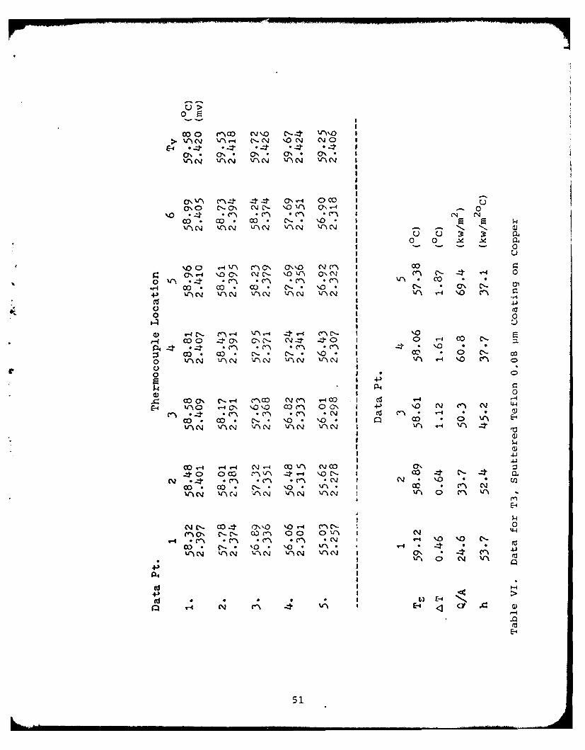
51
> (~ -:r NO ~ C)c\ al)(", C'- CQ I
E-4 .0 -:J' . * 4 *T .~ --.-
'4' C~l '\' '('C\ it 4.%N ') CV I U
0 nt' c' Nt C\ 4 0 7 n
NO '- \C'D - 0 Vn - C - I -( * o * * *-
C\1 %.0 4CDj U') Cv -Z N'- V- C\\ I u' * - e -'0~~ 0 z y-
NcN\ rCOW tc-I V'N o -%r\0 C C- 40 C- n VIA C C\ 1o 0 -4 E-
o '%C' C '- . \ '-4N C I V) n
4-)' C'. N N. (:\ .I V() -4 N~ Nl Eco 'N ''N IN IN N Va ~ - ~
0 I +) c
0)I C .- 0
r-4 '\'0 4- -4 \'0 V4'f V,) \0N I 4- cc C'- C ' C'-04 n 0 -* 0 --, - C- co C-'("I e, c"% 00 c'- *.1-4 .0 .0 . C7 *CO I Cl co *z 4 N 0o . 0. -* CO - V'% r-4 N~ Nq -Oi '(\I 'N 0?" 4- -4 k-4 1 4-4
0 -4 -4
ON0 ~ Q\ C% I,- CO '\CO o''N a- 0 CN\0 c0.% (\ 4Nl '('Co \04-I - CQ I CN 4 0 *
N~ .- *Q, .00 .00 -,0I 1' CN Nj N .CO. VINC* '. .4 ~ '' 0 N c'\
E--0 ON 0 4
4 at Ii I II III -i * .I \ 0 vs-4 0
I ''I 0 N 4-4 '
-4
52
o E
00~' n -40 01%cr rI V '% N \0OC'j I_>)-4 v0 0 C\ N 0 -40 40 1
O\' *4 *4 .C'i C4 *4(V V" 'rC' U\(\ 'Jv l C, N 14 N I
I u -u1 0 0 . 1 .
I) -4 -1 _:I -' - V% cl ~ -
\0W V nC' 400C C\' \ON \N I C\ N C~0'.0 .c~ n N . *Nj N C ~ * j IN '0 N
C ,0* ' 0.- ,0~ -* 4* I \0 * ;V) '~N 'IN V' Cj ) \ ' t' ' N 'C I W'A C\j VW C\
C'- O *- N 'N V^ C'.C 0"0 I7 00o -V' c N-'~ c -C f 0-40' 0 0O " '~- n " T-4 \Jo N~ n
*-r4 't *C"~ N *N *~j .N *N () C\ I V * 04- -. - 0 \ '0.\, \0 . - * 4 I C'- * 0 c- *
V'\N '~j ' V rN N'~ 'VN C~N VI 'j N " N z
0
1140 V- 4 4 'n - V' C-40 N4 C\aCSn .4Cj N~- .C\N qO '.00 I ON N0C-
o '0o . * -t o. 1- -4* o El -:I, r.0) 'C\N V.'\ N N 'f\N. U-\C N NrC' U"\CN V* \ -4 n~ N -
0-0 I c
NOC~ 4-,. r- -0 \0'i a3- r coV cn L- I (Z e lcoO'. co \0 N'- 0 cl"\co C.q-4 :24 - C\. \0 %n'
n o *N . -4 *,4 o -4 .0 .0 .* -l*N N. NV . cn . ON - ' C7, N c * CO -'
I 0
O'NC c C\O \Oco %r 'fcn- N'40 ON C' I CC)aC) -7:1. ' C" \ C NC\~ O\N 4Nt C\ N 1 0 c'n '0 4 z
NV *N .0 *0 *'-4 . () *C,, I N~ * 0 C. o - o .- * -4 . C- N C I CO I O ''A \N V* 'CV -( V'( N 4t- *,-I I 1 V-4 (1\
0
\0 n- COc'n' COa cr\ "C,-. NN N'- C '1 a \%0 144
NO- 00 oo 7\ 00- r0.\ c)co 0 '0 N~ (IN 0\ I~9-4 *N *\ .0 o -O- oN *C- I V'\ 4
n~ oa'- 03. a\* 4 4, o COt - 14 03 ocC1 4 4t- 4 4-I z 4 1 Vr 0 N 4
4;4
4J-
tC4 A E- CY a)4 *-4
53
u >
> .40 ON"a," a ONO -.40 'r)'.O ON O\ I uE-0 Y ..n .c' *Ci- . - *.2 * -,in I - 0
ON . 00 a3 00 - .. 0 * 00 .1 C14 C'NJVl 'J14 C~l U~N V*r N NO N i 'rCNJ I
0 0 -14 -1
0 Z o 0-t V C I ON-
%'o V\ CC) -4 CO "0 \ o' o rq- C'jo a'. 0 O,'. 0\0 .C *'\0 * .N -o . *:I N.I \0 -0\
%r\~ Ul ~ j -CJ l U\ \ tC14 '\~ W~j (\ I V" N 'N N~
'.0) C'-.- n ~ ~ x.r'. 0- xr~ m 0\ -40 0C\ 'O'J \0' 0c' ) *c-4 V'N\ \0 '' *NI V' "-0 1 0 \ \
o) N' - 0 n.0 .~ 0. r\ -4.' ' * 0\000 0 \ %.N 'J - '' N 'CI4C\ I -'~ O -N C\ C0
V' )Cj ViCj V CiI z r
P4:3 1 0
o n'. C -'.i4i "0 coC-- 0c' n N--o IUO N '.0-4 \ \0 V"O co 0 N-4 \10 0 1 \.0 .- r- ON
1D 01 C1 4-)
C.-O. ON. 0C i ON CN .- 4 -4 00 0\r N- 0 -4 0 -4 '\O \-0 -4 0ON. N n c' lN
-i .' . . rq-. ti4 ,O I 0 Q
0
NO CON C o 0 \0 \0C" n N C -Co ONr- -t " a)'. %, c O ON n 0--l CN-O\ N ~ N -q('.2 *N "- .- 4 .0 * 0 CO I N ** *
- V 0 N. C. o. 0. \.0 CO 1 0 CD o'('INC lc '("N _:rI 4Ni V' 4. -4 I C" C 4
I 0I 44
'\ 0 \0"O 0- C co0 C C o4 ONI 4J~4.;O N ON NO'.% V' n ''C n NNC-I N_ ON 0'(a
,.4 - .0 a\ *' *ON *C'- 1 1-4 * - 0.j* '- . LN. C-. - CO I NoC 0
'N %r\ C ~ V 4rCJ-4 1 4~ VN 0 N W)'
Ix
A4A
.0'-4 N ~ i '~ " IE4 .0 E- £
54
05
co(' VN n-4 n -4 n -4 n -4 O7% c>,4 4 0 v-4 0 -40 W-40 O c
ON~ (7, ON O\ (7% ( - 0NC1UfIN N'~' 'ti N VfN N ~ V'% S" 0
0 0\ n -4 W 0' N 0 -N7
41- n'.- . N .N" . CV CVc~ 1O 1- 0 N0 .(~ %r%
- *C' *N N -(. * I N0 O
as n Q co m'~' \ -4C C- C71 C.NI-I
. \O 04 W\0 'OC '4 ."- xn .~ -t -. 0 C4 , C V(- *CV *N V-% N 1- *.-N4' c I U4 Wi * *
0
04 \IN 0 I~ (1N mI WIN W. -4 co4 4-4 N "00 I
N,0 0 " 0 C\ I VI z\.4
Ol Ir .- No41C- oC
VS 0c'i trN O')N V OCO V CNOlN I +j V\c
\0(-% C 4. c1-
1- LI-. V 000 00~ N I CO a\ ~
0%~C QN CONV 4,N (C r C\ I ON 0)UN *-4 V1-4 .0 . C7\I n * C
A -t. -4 . 0'. CO. '0. CO 0* oi 0E- ifN %nN V')N V'\N 4-t 4.4IWq0 c
-
(V .04 0 .0 *O (7 .C *C\I N- * oN0 0. . N),. '0. \i, i CO 4-4fi
'%' WI V N 4'N 4 N w. 4-IW
044I
V -4 0 . 0C O - 0 \O
4;)
aS E-4**(f -4 N
fl w- N V;4Wi ' E-4 A1
55
02
>0 ON C'%~ 'ON '0. "'~~00 - CY .- O (JO (J
E-4 oo 4 \ C- .4 -4 *4, CV0\ '. 0%\ .n ' . ' 0%. Cj C\
\0% . O.\ 0 It' . 4 %r 'JO I U U
uuI0 0 .Sd .Y
O. r-4 -*v- 0 (\j1-4 \0('n I -
-4Cn 0 CN T--4 C\ N\JV,) V j IV -4'' V-4 4, 0Vt'\ .c" nc .N " N .~ "-j 1 0 c'- * U
-)
C. I
0Co 1t' N C' ' -4 V-4 C. C-~ VO I% M OH -t - ,. t\ 4 j C. q N. q I N * 'f 0 0:s ViN N -') N U-1 CN 'lN V"'.C'4 * I" V'\' C~
0 -P 0SP 4 C4
7' I +d
.C ' NO C0 co N n V\ 0 I -:2 N 4 '- 0E-C''\ C1 *C'j .- 4 .0 .0 1 0
0 4 - 0 - 0 - I S
40 n '. Na\ (VN 0-40 NCO0 0 00\1.0 No00 Vl 'I 00 o CO o V'% V" 4-4
W'3 *-1 .- 4 .0 .0 *l % I N *N%4. '-4' . % (Y, I ~ co Co * COt
04C~ V) N -:J 4,-4 V) C", \10
('JCO 0 -:2 0%'\ U'04Z c - 1.0 \0 a\ 0 \
-4 0) NV -: -4 0 a)" % - ,'vi
P-4 1-
(IS4.)I(dS 0 0.(j - N
N C~i V~ I<E-4
56
ccm \0N~ 'ON (n C' Cl- ,\-4 1
&E4 Zr *4 *t 4 .4- I
UAN N V-% 'A - ~ VNCj 1N IA
,-4NNON -4a: ~ OC'~I
\ 'An 'AN 'CN CJ N 'c I2 2\0 -- N N
I0 0 .
0
ON .n0 N\ N ON~O4N O C
.o- c'0a N N' N'0 .-40 cO7\ V' V' 0 00
4+ '% -c *c-N n N 'Nj * I VA * CO r.*
cr3 N'- N. A - & I Nl " 00 .1
\nN'A 'AN ') 4 VN~ IA 'A f 'A C%4N4
0 0
\0 'ON CN4 N.-4 0\O -'0- I~ NO 4 N
0o *N *Nj *NJ *d *-4 4 O
C. 'A' 4' - * CeN N'J N I 0 W-4
o l 'AN 'AN CV N '\AN 'N 'A I- %r C-\EI
>1
r 0 -
C'~~N 4C)'4 0~O 4N 0 C
4. C ("I%* co C-N 0'~i Cl 0 IO *o 0
c("\ 'AN CO ACN 'AN 'OA::- I c 0 co 'A$
I U0 - - Y
(V=' 40VNN ' ~j U' 04 V AC\) I N C" 0 44
nJ.- ..- e 0 \,o %n l N, N N
N. ' 0' CI- VNn I O * N N
'O N.0 N .ON-\ 1 N~NON C'-C -N 1~C 0*'i C- 'A N0\
w-4 . a CO . NO 'A 1 00 N ON
'ANCl :: _zt 4.-' 4 4'r I ' 0 CI C'i
4;H
cr3 .. . . ~ I) E-4 E..
57
02
w- C-- *4 4 C, C, V'4v,,> C- 0' n 0'n'\ 0 0'.' e 0 1 -
N u
Cc avo a'.O \C'.4 (-4 zt r\C COD r ~ 4r- -4 wC-(. C- C>- 9-4O COO' cN o"V C'- -:t \0 0
'0 n *cj .N *CJ *N *v .- I . .I g '.0\0. - " '- 0 4.t (I\- C1\ * Nv
0
0 C\ N n (71, .- co VI~\4 ~ .C'. N- I~ m -4 0 .14.r4 . c *C *Nq *Cj *j * j *-4 1 CO * 4*
4-3 -,o \.0' . '. .' --t . \ - '\0 * mo N
aS vC..i 1CC' '\ j N.~~ V'%e iCrcl V' N>, I. V\.l 0
4) ' ' 4 Cl 0 C) \ \ I Lfl
P4 0 .'- (0 \ CC)O CN(V -:"n N n O 00C- '. 0 ZP4 0 0-*4 ~ -C~" .o ' crj 4 C\ q o v4 . 0 V0 0 . : .N *N , 'C. J N'- *. 0 . I \0 * '.
o 1 P4- 0
4) 0
E-4 z N C- --t N co cl- 00 '.N #-I' V aS 0 0'.r 10 X v o'.4 n " cr I Cl-C 00 1 C'- Nl- -4 \.0
C''I *N .- 4 w-4 .0 .0 U I* '. * *
"\N VC~N U-)N ~Ic\J -:t-4 4r- n Ci iI j
N0 NV oa ' \ \0 I IY
tC-i0NO N COO" C\W' O'.0 No--nC 0 0(
COO .- c NO. 00 C04 C'D - I C- c -fN ' .c' '-4 .0j 0'j 40 1C g' N 44f'
4.1
:t40 4Nl '-IN 00 nCC- NO'\ I co I
C-. 4"'_r 0 " IN (I"\O w _Z . \- \o 0 ON. 4 %0v- w4 .0 .0 .'Co CO .(. 1 v-i . -
('.3. 0' - (\ \.0 V"\ (V"% C00 ~ ''f' CVJ %C~J 4Nj 4,-i *.i 4- -q N~ T-4 H
aSE- E-l) E- N
58
C-v C-~- 4t 04fM Nc ON ao I>.(~ - r0 C'- 0 C-CC I
'dVC V') \j V"' C'j ' N '% C V li~ I2
0 0
N C4 - -- co C 0 .eN CO *WN
N~~~ ~ ~ ~ rA n a,-,C -+ -.- \ C " ,
I
0 Nc- \0' N ~ \ nC~ *C:t V'\4 '0% *" N? *4
IN~ --t U"o -t'4 C%4 ccy\ *. \0 00 1C 4 \0vcn I C~ 'J. 1'C'4 ~rC14 -J' I 4 I% V CO0
C - \4 ' - Na' V' - ' 00- '-' --I -N NDU' *C"' *' ~j V *C'. *N, *~ )Cj N * I " '\ * * \)
0I
Ui I0 v-CN N'O \0 0 \, O 4i- C4 C C CO I %r\I >4
c 0 N'.j-1 - \ 4N o a\OU C'- -1,C\' I 4' 4 4 x4 c~ N N *w- *-4 .0 1 4*N **0
V- V'% IN C\ Vt' ~CN %r\ 't'C' V'4\ N~ V% 4 N 0)*q 0
E2 l l n'. '\ 4( 4 -4 \X)' C\ CNN I 4- N
p 'l .0 coO co \0 \.0- CO C- CO C' I cl. c- C'- 0 If
4 t4 0 n . N*J -4 0.- CO -I N- * l \' 0 uV- \ 14 V'%N V'% N V'\N~ V'\N 4v1 -:2. r-4 n N
C7 0\I V \ c 4C o-
U01% n- C) C- \o N MO 4CO T -4 N3 -4 V-4 4-4NV *N C~,- .0 .0 .0. *O N * N
n -. N. 0'- C CO* \0O* 00 cn- N- toV) N V"N 't'j 4N Nv- n~ 4~i4 c N 41)
* .0 .0C .Q *QE) *C- co x
'('I N U('I N N 4v: 4 4~ r 41 4 (' 0 N N Q)
4.) I .
Q \r% N\AD 4 V ~ ' I E-t < CY .C
59
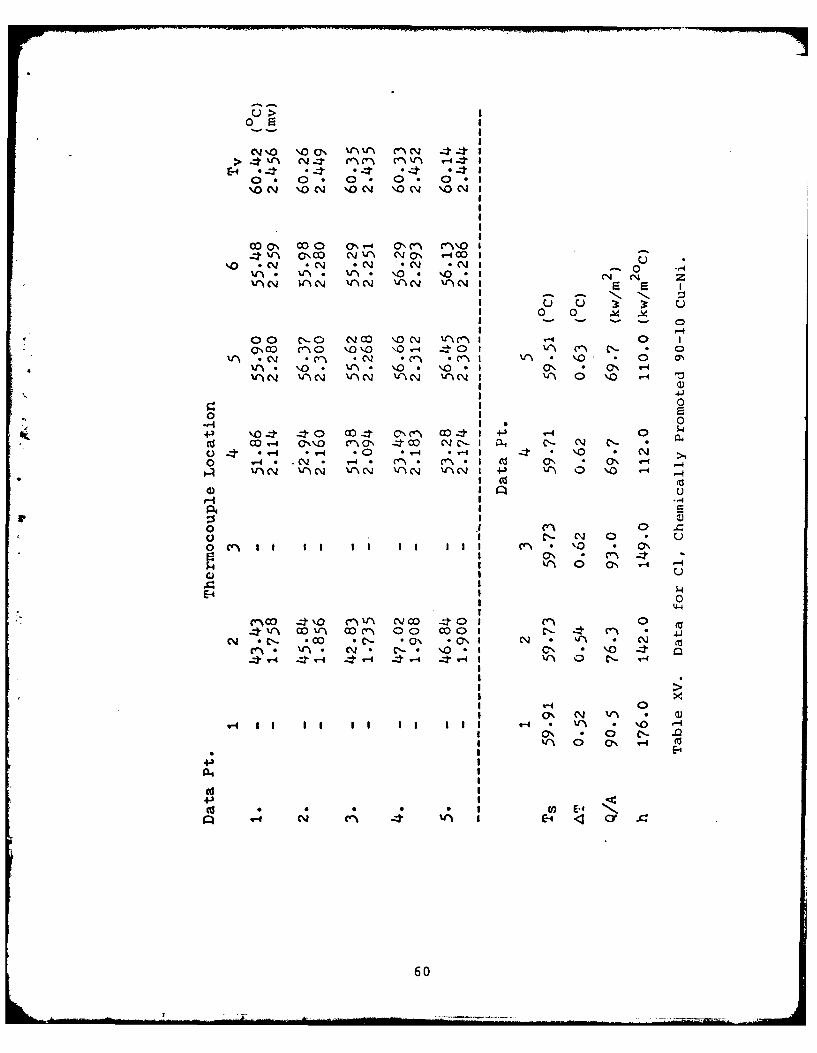
u >02 E
> ' V-% a 'tWv -:t 4n Ir
0t 0. 0 . 0 . 0No N 'N 'ONCj \ % 4 OV 'O I
00~ CO 0 (7%V- C\0' cn U""
* ' t C7 cN *N j * C4 I 0too-I%j. 1. V . %4 CV ' l 1 0
vl - V) - - -. CN
I 0
00 C- C0 4 N m\N 'V\c n- 0o'~ n -0 '.0'o o \0. 40 1 n~ C N *
V*~. 0. n f~ nO I0. '. o . 0-\,O .iC~ - "\N . tC I 't' 0 0 -I '
I a)1 4.1
g 0
r4 0
cd CO q-4 0'.'.0 n CN 4 c N -I aq N ~ N -NaC) *.-4 . .0 . -4 .- 4 4 .0 > N0 -4* . . ~. e . CVI CU\ -4*O~
UVA \j -'tC.j N XN PN .) ' 0 '.0 '-
o 1C - 0 u0) lr C- N 0
E-4I 'I 0 0. -4 -g U
%f-% coP V.) oo 00 000 1 N, n 41*
N .C- . N* . '. 0\ y*I 0'. V '1 4 m
0 V'N N - - - a N '10'. 0 0 T-4
04I
60

0Oco rl\N O(V 000 aO I> no %0N 0e~ n4
E-4 0*T * *4 *
Ul% C1 V'%N NON 04 %0N I
q-4 0 coO 'c "' VI l - I
% OC,% 'O C --% .O C-ON 1
C% 0 C, - O CC)o
I 0
01\ ON'\O coo 0 coo I u 0
lJ\uN 0 ~' n n 0 rJ
o I ~ - . N N 0
.14 u u 3
+1, 0 0 1%4~
W- coo C'4C nOr' C- 1' a, C
C: ('-1 0" n n n 1 0*
0 C- \O* . o Co. ON CO C '-
HA V)C\) VClN 04 'I v I V-\ 0 O -
Ui I *
rz -4 - N C- N~ n N I a4 I$4 \ON NOj C140 NO WIN\O I 4 k '0 Co * 4
.') n O - 0 C'* .- n 4-' ON . no t nV1 . c-4I' I0 0I WIN - C- WI+3 0 00 '--4 -
E- CC N%\ CON Ccl I C'- 04
ooi Wc. N \* ca Cl *o Ne I
* WN WIN WIN WI ' Cj VN N IWU- 0 q V-4
03 C-
ul Co l C' 0 E
Id V)i 0E -44-
4-61

>~Cct (' N -WNN k4 a c'-4%-cc)-4 CN- C-CNcoC
(-4 . * .4 r4 .E.CIN O~~ CN ' ~N()iNI
I 0 0 .
N C. M -~ 0, o" e -3 * NO%4D CI n~ \) 04j 4- "0 ' '0 -a, C'.- * 0 * * N .
n C C,% I n
0 00
oo 44- 40 N'o '-4 NC'- CmI4 * C'01. 0C- *i N " N --4 \ .0C o1 4, - *- N 4
C- * o 4 * *n V-4 V*I C-'44'('N V Ns ' N 'V'aC\ N raCN V 'aN I
g.I Q)AI
00 -P \00 c'-'a N4 CJ\ (I-4co *Cai c ~ a 0 CS0 C\- NC C"- a% a N0 ani C 4 *
0, C'0 N C- n Na3v a, i .1"' *4 C-'
CI co-i
0
N ~ ~ c *7N U\4 -410.0 CI '
'-4 -00 4 . 12
V' N V4"\ 0 N nfh ,
4.) I (>
00) x04 *r n CO 0 I(1 -,
Q - Nn \40 41h' 0 E-4 <3 Cy .
62
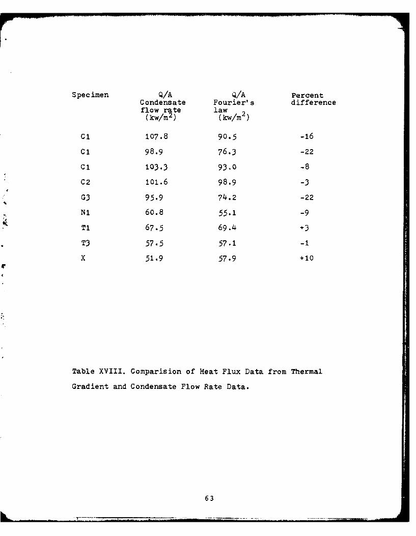
Specimen Q/A Q/A PercentCondensate Fourier's differenceflow rate law(kw/m2 ) (kw/m2 )
Ci 107.8 90.5 -16
C1 98.9 76.3 -22
C1 103.3 93.0 -8
C2 101.6 98.9 -3
G3 95.9 74.2 -22
Ni 60.8 55.1 -9
T1 67.5 69.4 +3
T3 57.5 57.1 -1
X 51.9 57.9 +10
4.
Table XVIII. Comparision of Heat Flux Data from Thermal
Gradient and Condensate Flow Rate Data.
63
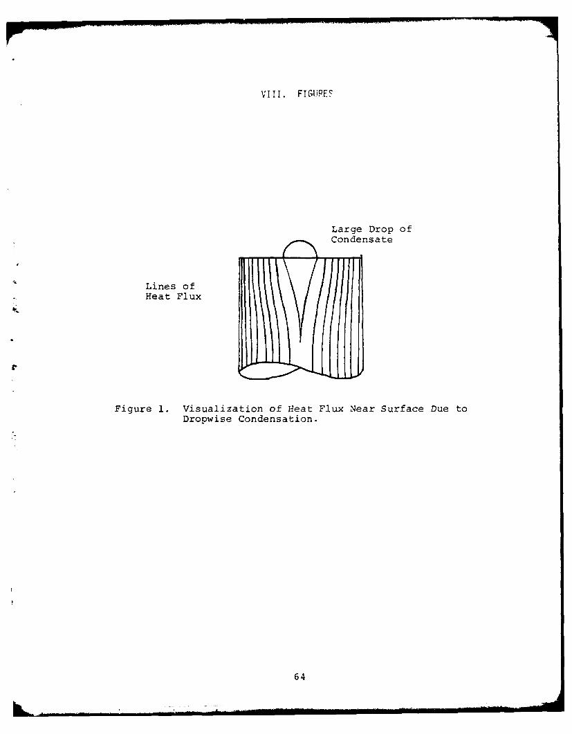
V!II. F IGURES
Large Drop ofCondensate
Lines ofHeat Flux
fr
Figure 1. Visualization of Heat Flux Near Surface Due toDropwise Condensation.
64
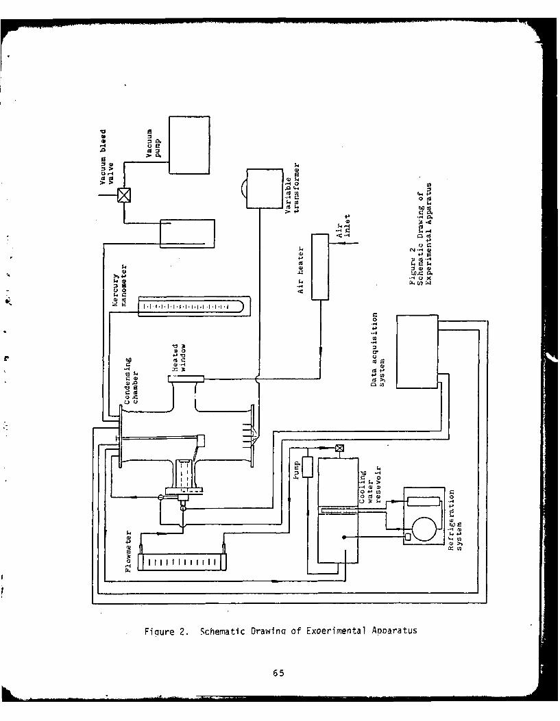
21ap
>~ 14
u~
0 CS
4
54 4J
Ga 00~
.54 39 C) 4
4- W
CCo
V3
0) a' r0* VS w0
44-, to
654
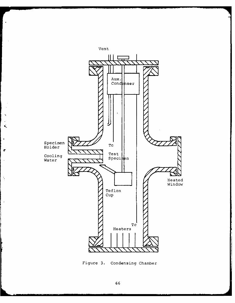
Vent
II I.
Aux.
Cond nser
< j "
Specimen NHolder T
Cooling Speci nWater
HeatersH
Figure 3. Condensing Chamber
66
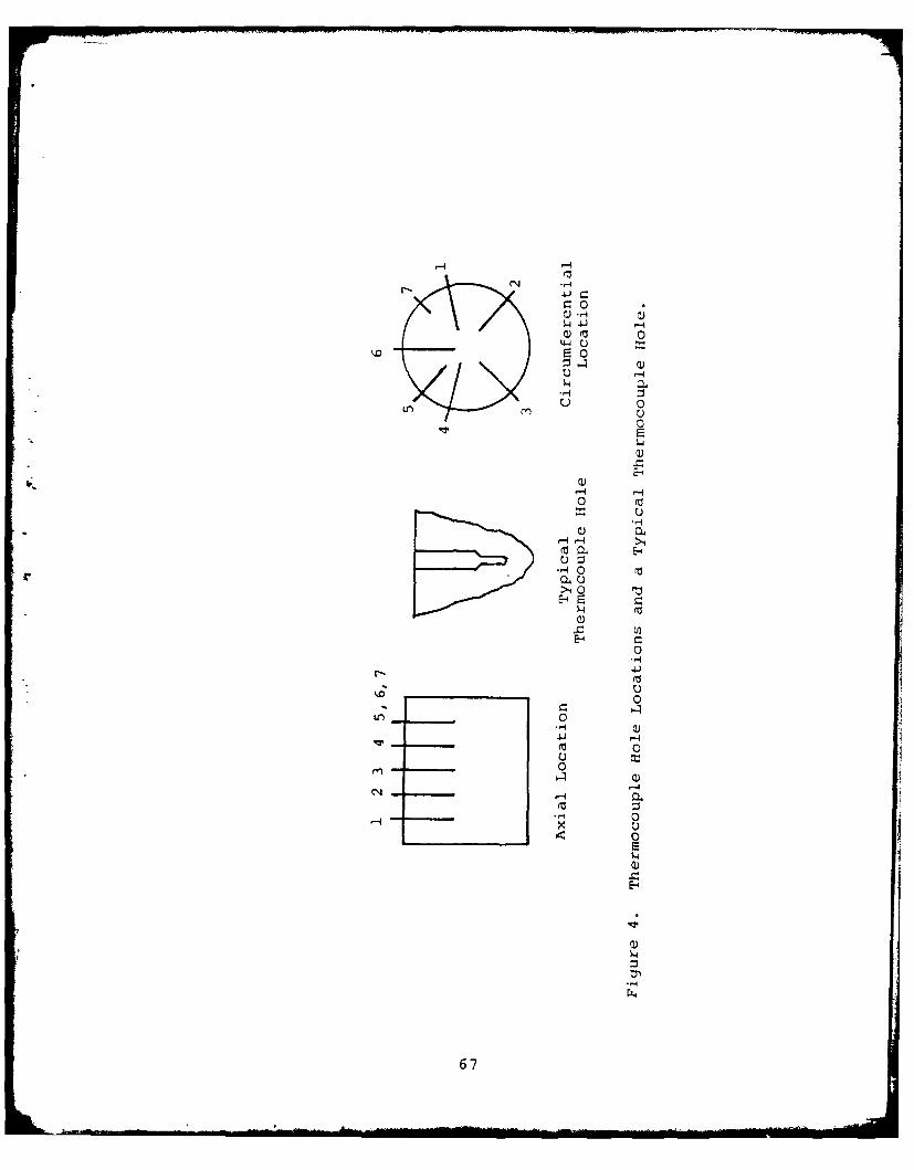
41z 0
0) 0
0
I 0-4
0
2
.4-
~0
-4 -
S0
0 a
!0
-4
0auH>141
0
U, 0
4~. IJ -4
M 0
-4 -E-0
-4
67
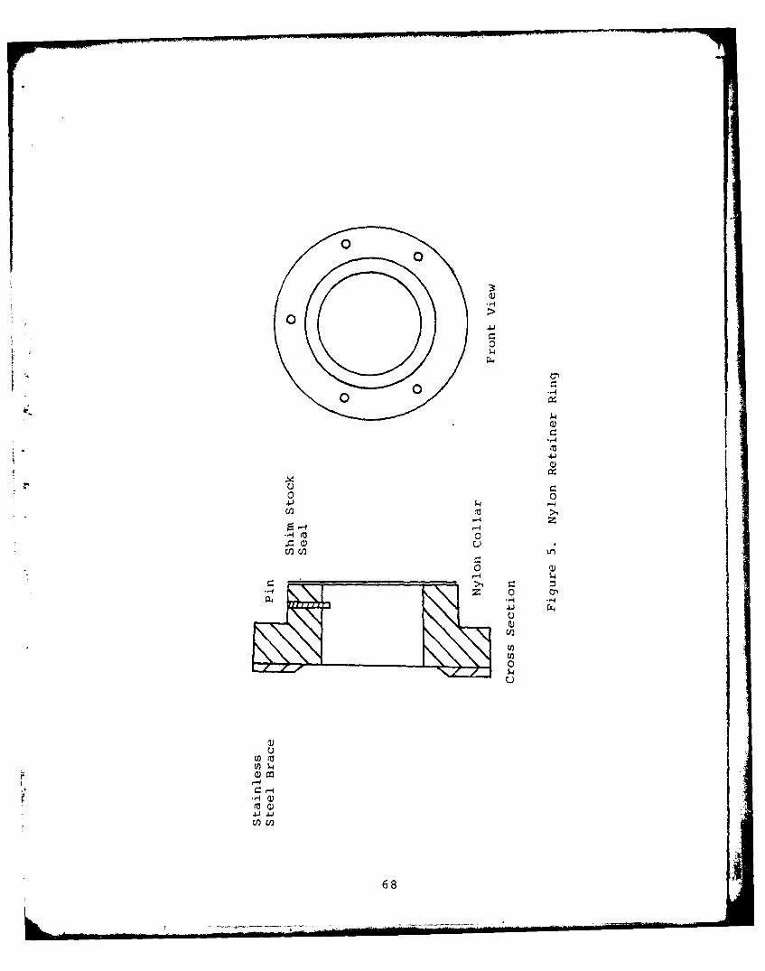
4-I1
Q)
0 0
U) a U2)
U~CJ2 68
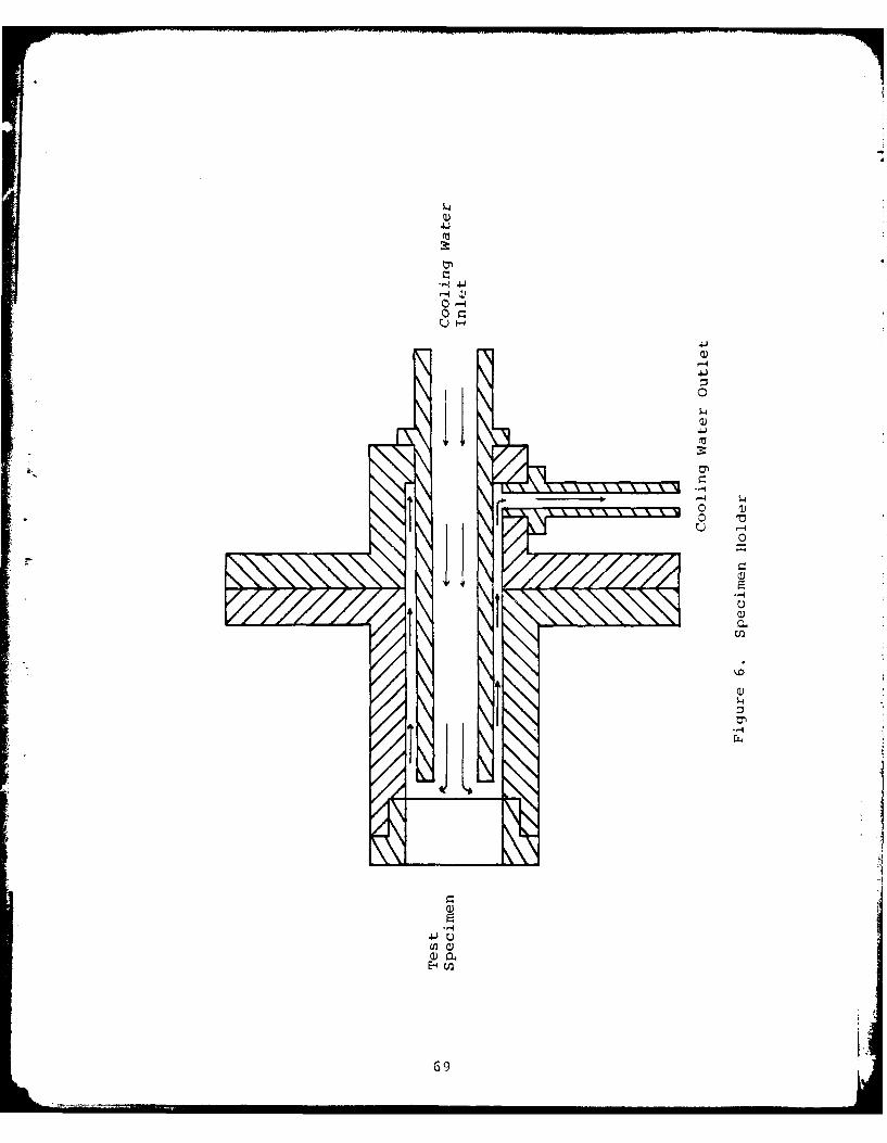
414
.4C)-4
U)~
o -
C-69d-
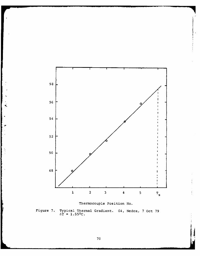
58
56o
54
52
50
48o
1 2 3 4 5 TS
Thermocouple Position No.
Figure 7. Typical Thermal Gradient. G4, Nedox, 7 Oct 79
AT 1.55 0C.
70
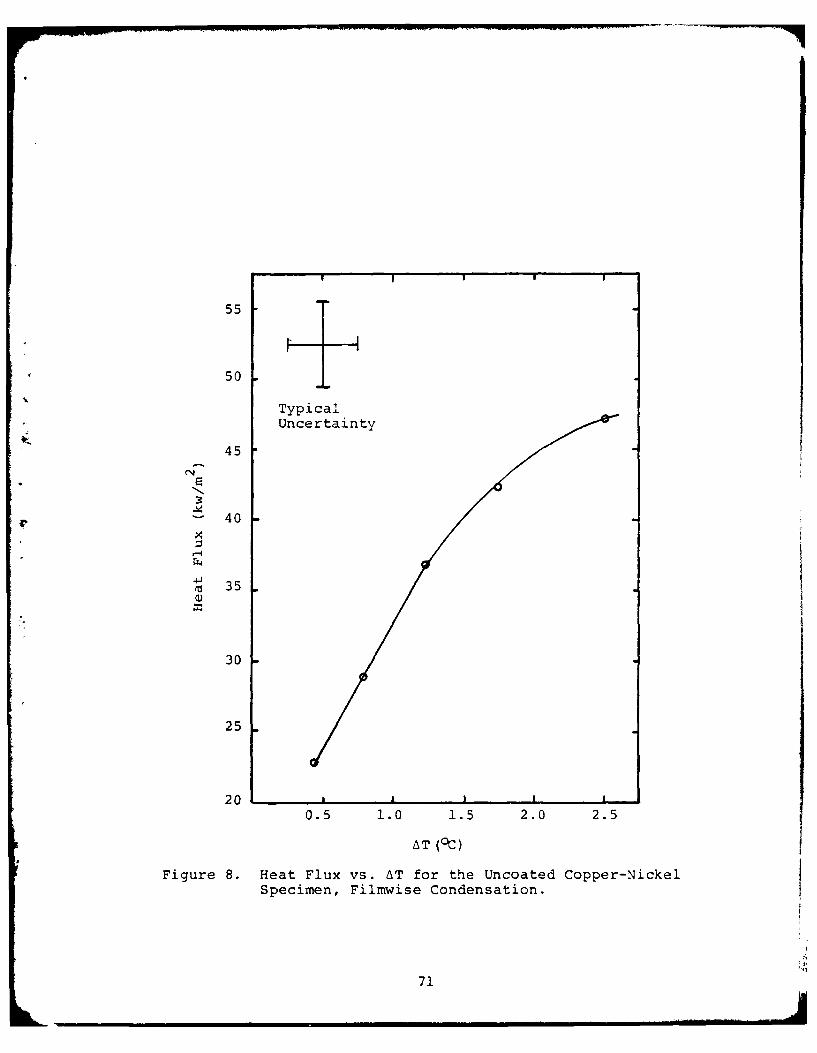
I !III55
50
TypicalUncertainty
45
-" 40
.x
--
M, 35
30
25
200.5 1.0 1.5 2.0 2.5
AT (°C) IFigure 8. Heat Flux vs. AT for the Uncoated Copper-Nickel
Specimen, Filmwise Condensation.
71
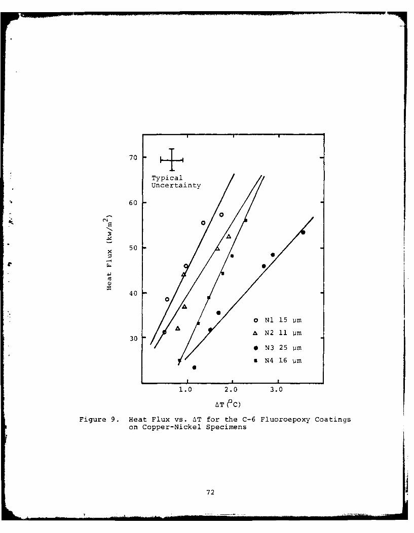
70±
TypicalUncertainty
60
- 0o
50
r 40
0)0
300
* N3 25 pim
*N4 16 'im
0
1.0 2.0 3.0
AT eC)Figure 9. Heat Flux vs. AT for the C-6 Fluoroepoxy Coatings
on Copper-Nickel Specimens
72
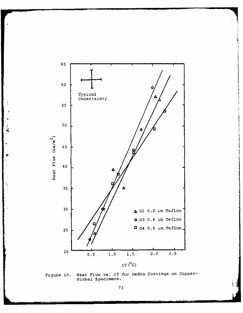
I
65
60
TypicalUncertainty
55
50
0
* 45
-4rZ 40
35 A
30 -A Gl 0.2 am Teflon
0 G3 0.4 pm Teflon
25 G G4 0.6 im Teflon
I I I I ,I20 0.5 1.0 1.5 2.0 2.5
AT (°C)
Figure 10. Heat Flux vs. AT for Nedox Coatings on Copper-
Nickel Specimens.
73
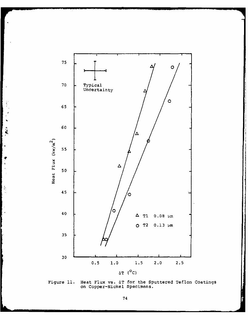
p I o75
70 TypicalUncertainty
65
60
3 55
rX4 50
45 0
40A T1 0.08 vim
0 T2 0.13 pim
35
30
0.5 1.0 1.5 2.0 2.5
AT (°C)
Figure 11. Heat Flux vs. AT for the Sputtered Teflon Coatingson Copper-Nickel Specimens.
74

o 0 0 0 0-4 r- r-4 1- 1-44 '4444 44 t4-4
(1 ) a) 0) Q)E-( E E-4 E4 E-4
( 4 CN I"
.- ; C) .I
*E-4 E-4C C.40 0 n 4-4
r 0
U)
4 cQ)
4 1 u(4 ) E-4
u >)
E4 U)
1>,
0'
co 4oE-4 -
I I L
(N * S.- ,
0IM 4:a3T90 aSVI4H
'-s, ~ j75
. 3 .-....A
APPENDIX A
UNCERTAINTY ANALYSIS
The uncertainty in heat flux and surface temperature were
determined using standard statistical techniques. Miller and
Freund [19] were the source for the basic equations. The un-
* certainty in surface temperature was also calculated using the
Wilcox method [20], because it is almost niversally used.
The uncertainty in the heat transfer coefficient was calculated
using the method of Kline and McClintock [21].
A.l. Uncertainty in Surface Temperature and Heat Flux
T = T + mx0
n 2 2S nZ x - (Exi)
xx i=l
2 1 nS Ti - (T o + mx)]2
e ii~ i=l[Te H-2
S : + (nx)2
xxam = +a/ 2 "Se #
ta/ 2 = 1.638 (0.8 confidence level)
aT = The uncertainty in the surface temperatureAT
am = The uncertainty in the slope -T
aq = am " k
76
A.2. Uncertainty in Heat Transfer Coefficient
q/ 1AqA )2 +A,,T 2]71
ah = [(q-7-) + (-T-)
ah = The uncertainty in heat transfer coefficient
A.3. Wilcox Method
Q/A
T T5 =S - dT s w k
s~w n.SW~ n Z(x. 2
1 i
n = Number of thermocouples
d = Thermocouple hole diameter
x. = Distance of the ith hole from the wall
A.4. Range of Uncertainties
Using the Wilcox method [20], the uncertainties in
surface temperature are as follows:
Copper +0.050C
Cu-Ni +0.280C
Ti +0.30°C
Using the standard statistical techniques, the uncer-
tainties in heat flux and surface temperature varied as follows:
Surface Temperature 0.2 to 0.4°C
Heat Flux 1500 to 3500 w/m2
77
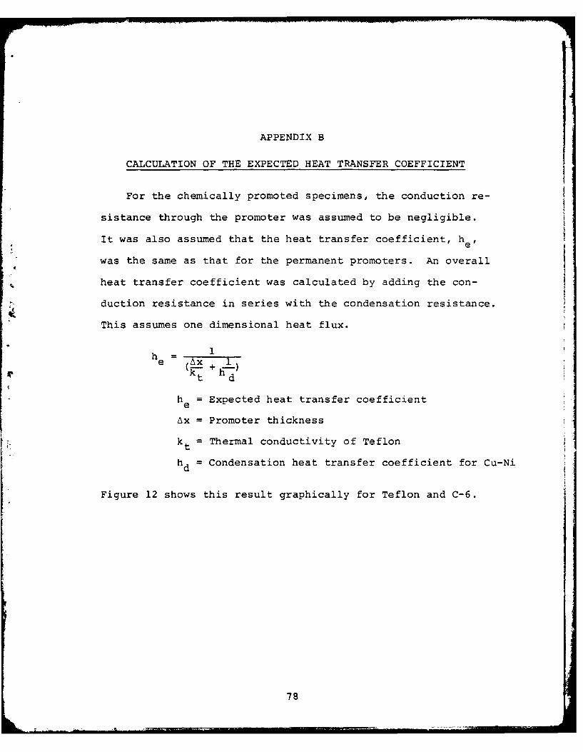
APPENDIX B
CALCULATION OF THE EXPECTED HEAT TRANSFER COEFFICIENT
For the chemically promoted specimens, the conduction re-
sistance through the promoter was assumed to be negligible.
It was also assumed that the heat transfer coefficient, hel
was the same as that for the permanent promoters. An overall
heat transfer coefficient was calculated by adding the con-
duction resistance in series with the condensation resistance.
This assumes one dimensional heat flux.
1h 1e (' x 1
k h
t d
h = Expected heat transfer coefficiente
Ax = Promoter thickness
kt = Thermal conductivity of Teflon
hd = Condensation heat transfer coefficient for Cu-Ni
Figure 12 shows this result graphically for Teflon and C-6.
78
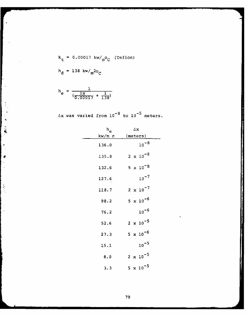
kt = 0.00017 kw/moc (Teflon)
hd = 138 kw/ m2oc
1h 1
0.00017 +138
Ax was varied from 10- 8 to 10- 5 meters.
he Ax
kw/m c (meters)
136.0 i08
-8135.8 2 x I0
132.6 5 x 10 - 8
127.6 10
118.7 2 x 10
98.2 5 x 10 - 6
76.2 10 - 6
52.6 2 x 10⁵
27.3 5 x 10 - 6
15.1 105
8.0 2 x 10⁵
3.3 5 x 10⁵
79
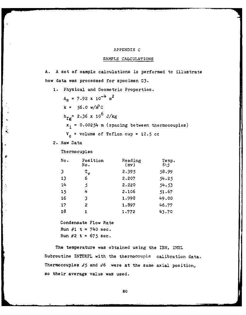
APPENDIX C
SAMPLE CALCULATIONS
A. A set of sample calculations is performed to illustrate
how data was processed for specimen G3.
1. Physical and Geometric Properties.
As = 7.92 x 10⁻⁴ m2
k 56.0 w/nC
hfg= 2.36 x 10⁶ J/kg
xi = 0.00254 m (spacing between thermocouples)
V c = volume of Teflon cup = 12.5 cc
2. Raw Data
Thermocuples
No. Position Reading Temp.No. (my) (,3 TV 2.395 58.99
13 6 2.207 54.25
14 5 2.220 54.53
15 4 2.106 51.67
16 3 1.998 49.00
17 2 1.897 46.77
18 1 1.772 43.70
Condensate Flow Rate
Run #1 t = 740 sec.
Run #2 t = 675 sec.
The temperature was obtained using the IBM, IMSL
Subroutine INTERPL with the thermocouple calibration data.
Thermocouples #5 and #6 were at the same axial position,
so their average value was used.
80
-A!

Position Thermocoiple Distance from
No. Temp. ( C) Surface (m)
5, 6 54.39 0.00254
4 51.67 0.00508
3 49.00 0.00762
2 46.77 0.01016
1 43.70 0.01270
The above data was evaluated by the method of least squares.
A Texas Instrument TI-58 calculator with a built-in linear
regression program was used.
T = 56.99°Cs
AT _ 1034.65 C/
Q =-k -T -(56) (-1034.65) 57.9 kw/m2A Ax
Qh A 57.9Tv-Ts (58.99 - 56.99)
h = 29.0 kw/ m2o C
Calculation of heat flux from condensate collection data.
Q = mhfg
"- m
in = V
mi (983.28) (12.5 x 10⁶) 0.123 kg
81
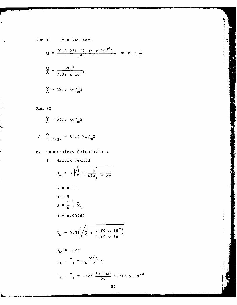
V
Run #1 t = 740 sec.
+6(0.0123) (2.36 x 10+) = 39 2
Q _ 39.2A -40
A 7.92 x 10
Q- 49. 5 kw/ 2Am
Run #2
S- 54. 3 kw/ 2A m
Q =51.9 kw/m2A avg. m
B. Uncertainty Calculations
1. Wilcox method
S w S(x i 1
S = 0.31
n= 51n
' = -{ E x i
= 0.00762
0.31/ 5.80 x i0
6.45 x 10 -
s= .325
- Q/AT-T =5 -d -
TS s w k d
T - = .325 57.940 -4 5.713 x 1
82
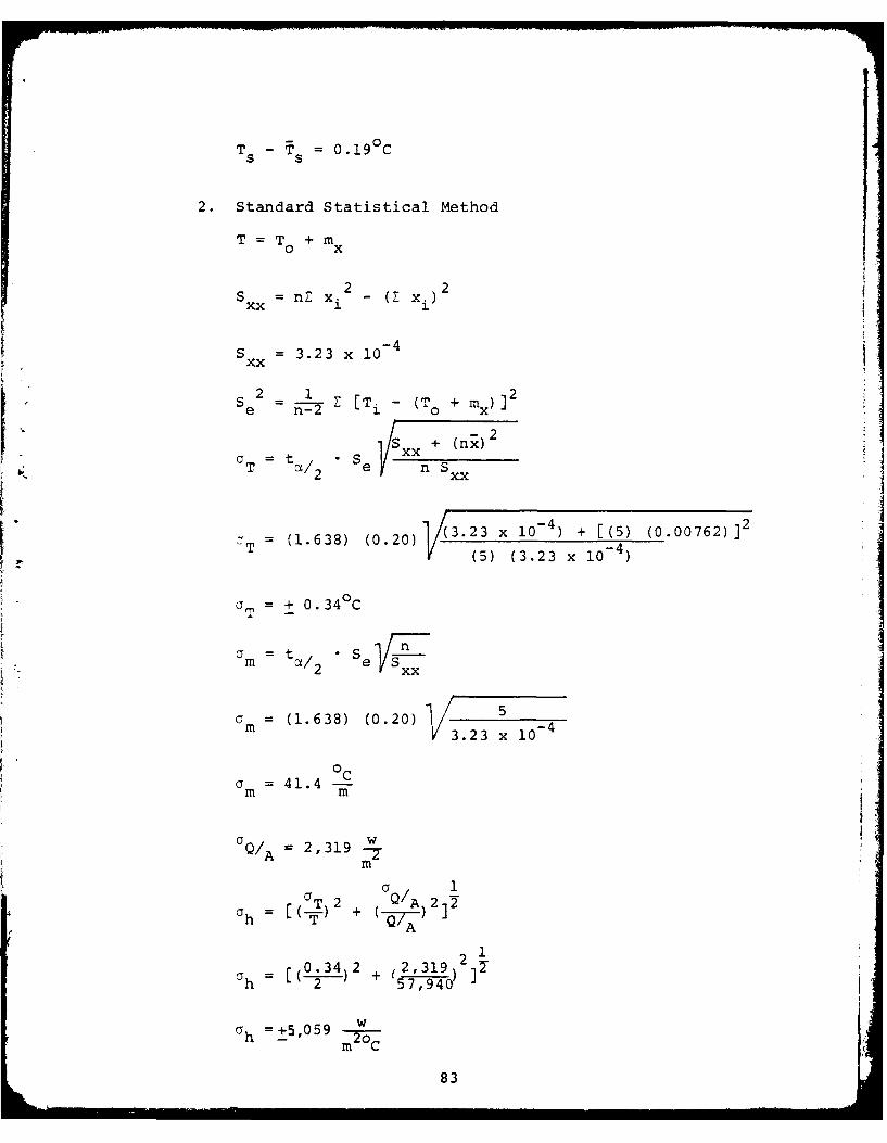
I0.
T - Ts = 019
2. Standard Statistical Method
T = T + m
SX =nZ x 2 ( x) 2
S = 3.23 x 10 - 4xx
2 1 2Se n- [Ti - (To + mx) ]
S + (nx)2aT = t/.Se xx2 Sxx
T =ta/ e ~ ~ +(4 (0.00762
T (1.638) (0.20) -43.23 x 10 + [(5) 2)]~~(5) (3.23 x 10 -4
CT = + 0.34°C
a =Sm te ,
m = (1.638) (0.20)33 x 1
0 C .y = 41.4 -m m
aQ/= 2,319 w-m
0 T 2 + Q/A 212ah = [(0) + (-7-3-19
03 (2F39) 2w 57,940
ah = +5-,059 ---
83
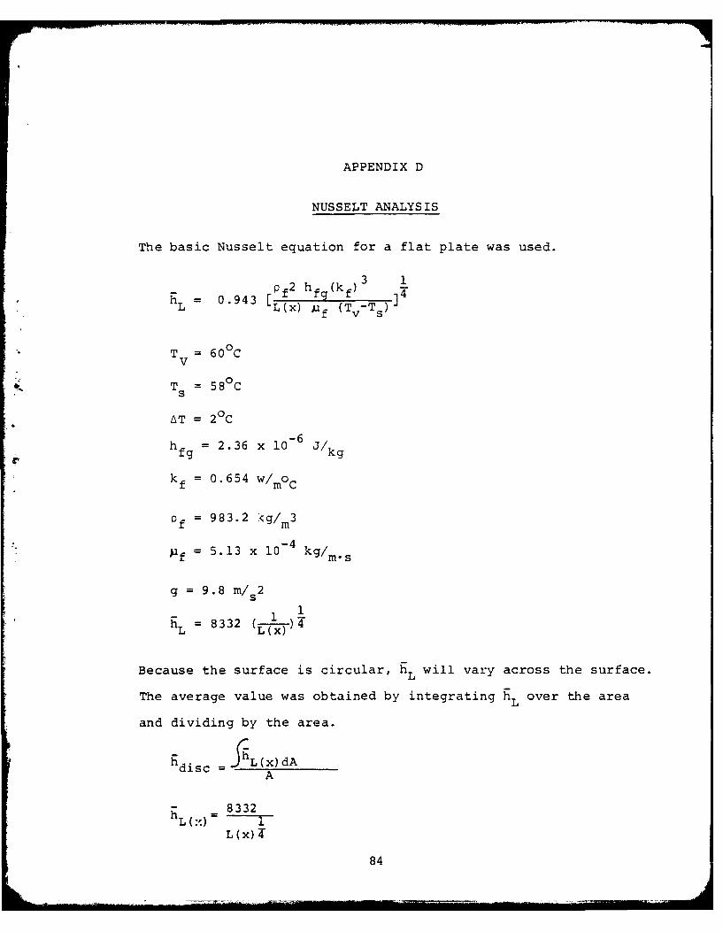
APPENDIX D
NUSSELT ANALYSIS
The basic Nusselt equation for a flat plate was used.
f2 hf (kf)3 1h = 0.943 [Pf hfgkf 3 1
L L (x) )ifTv-TS
T = 600 CV
T = 58 0 Cs
AT = 2°C
h = 2.36 x 10⁶ J/kg
kf = 0.654 W/mOC
Qf = 983.2 <g/m 3
f = 5.13 x 10 - 4 kg/M*s
g = 9.8 m/s2
1 1h = 8332 (f--
Because the surface is circular, hL will vary across the surface.
The average value was obtained by integrating hL over the area
and dividing by the area.
hdisc =JL(x) dAA
h -8332h L :=
L(x)84
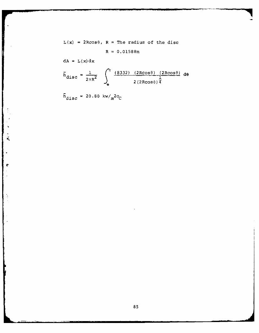
L(x) = 2Rcose, R = The radius of the disc
R = 0.01588m
dA = L(x)dx
h 1 (8332) (2RCose) (2Rcose) dedisc 2TrR 2 1
2%'2Rcose)4
h disc= 20.80 kw/m2OC
85
BIBLIOGRAPHY
I. Search, H. T., A Feasibility Study of Heat TransferImprovement in Marine Steam Condensers, MS Z, NavalPostgraduateSchool, Monterey, Ca., December 1977.
2. Jakob, M., "Heat Transfer in Evaporation and Condensation-II,"Mechanical Engineerinz, Vol. 58, 1936, pP729-739.
3. Tamman, G., and Boehme, W.,"Die Zahl der Wassertropfehenbei der Kondensation auf ver schiedenen festen stoffen,"Annalen der Physic, Vol. 5, 1935, pp77- 8 0.
4. Graham, C., and Aerni, W. F., "Dropwise Condensation:A Heat Transfer Process for the '70s," Naval Ship SystemsCommand Tech. News, Vol. 19, July, 1970, pp. 8-15
5. Tanasawa, I., "Dropwise Condensation: The Way to PracticalApplications," Sixth International Heat Transfer Conference,Vol. 6, Toronto, Canada, August 1978.
6. Hannemann, R. J. and Mikic, B. B., "An ExperimentalInvestigation of the Surface Thermal Conductivity on theRate of Heat Transfer in Dropwise Condensation," Int.J. Heat Mass Transfer, Vol 19, 1976, pp 1309-1317.
7. Rose, J. W., "Further Aspects of Dropwise CondensationTheory," int. J. of Heat Mass Transfer, Vol. 19, No. 12December 1976.
8. Graham, C., The Limiting Transfer Mechanisms of DropwiseCondensation, Ph.D.,MIT, Cambridge , Mass., March 1969.
9. Erb, R. A., and Thelen, E., "Dropwise Condensation,"First Internatonal Symposium on Water Desalination,Washington, D. C. October 1965.
10. Wilkins, D. G., Bromley, L. A., and Read, S.M., "Drop-wise and Filmwise Condensation of Water Vapor on Gold,"AIChE Journal, Voll9, No. 1, January 1973, PP. 119-123.
11. Woodruff. D. W., and Westwater, J. W., "Steam Condensationon Electroplated Gold: Effect of Plating Thickness," Int. J. HeatTransfer, Vol. 22., 1979, pp. 627-632.
86
12. Smith, G. F., Promotion of Dropwise Condentation byTeflon Coated Tubes, U. S. Naval Engineering Experi-mentation Station, Annapolis, Md., Evaluation Report030038B, NS-643-078, 12 Oct. 1956.
13. Coxe, E. F., Investigation of the Use of Non-WettingAgents for Promoting Dropwise Condensation By TeflonCoated Condenser Tubes, Westinghouse Electric Corp.,Lester Works, Heat Transfer Department, EngineeringMemo EM-377, 19 May 1959.
14. Manvel, J. T., An Experimental Study of DropwiseCondensation on Horizontal Condenser Tubes, MSME,Naval Postgraduate School, Monterey, Ca., June 1979.
15. Sharp, L. R., An Apparatus to Measure DropwiseCondensation Heat Transfer Coefficients of Steam,MSME, Naval Postgraduate School, Monterey, Ca. March1978.
16. Tanner, D. W., "Heat Transfer in Dropwise Condensation
at Low Steam Pressures in the Absence and Presence ofNon-Condensable Gas," Int. J. Heat Mass Transfer,Vol. 11, 1967, pp. 181-190.
17. Morgan, J. M., Some Experimental Observations ofDropwise Condensation of Steam, MSME, U. S. NavalPostgraduate School, Monterey, Ca. March 1977.
18. Griffith, J., Naval Research Laboratory ChemistryDivision, Washington, D. C., Private Communication.
19. Miller, J., and Freund, J. E., Probability andStatistics for Engineers, 2nd ed., Prentice-Hall, 1977.
20. Wilcox, S. J., and Rohsenhow, W. M., "Film Condensationof Potassium Using Copper Condensing Block for PreciseWall Temperature Measurement," Trans. ASME, Journal ofHeat Transfer, Vol. 92, 1970, p. 359.
21. Kline, S. J., and McClintock, F.A.,"DescribingUncertainties in Single Sample Experiments,"Mechanical Engineering, Vol. 74 pp. 3-8, Jan. 1953.
22. Heat Transfer Data Book, General Electric Company,Schenectady, NY, 1977, P. 515.23-3.
87

23. Touloukian, Y. S., Thermophysical Properties of Matter
Vol.1, IFI/Plenum, New York, 1970, P. 81, 414+.
24. Holman, J. P., Heat Transfer, 4th ed. McGraw-Hill, 1976.
25. Reynolds, W. C., and Perkins, H. C., Engineering
Thermodynamics, 2nd ed. McGraw-Hill, 1977.
88
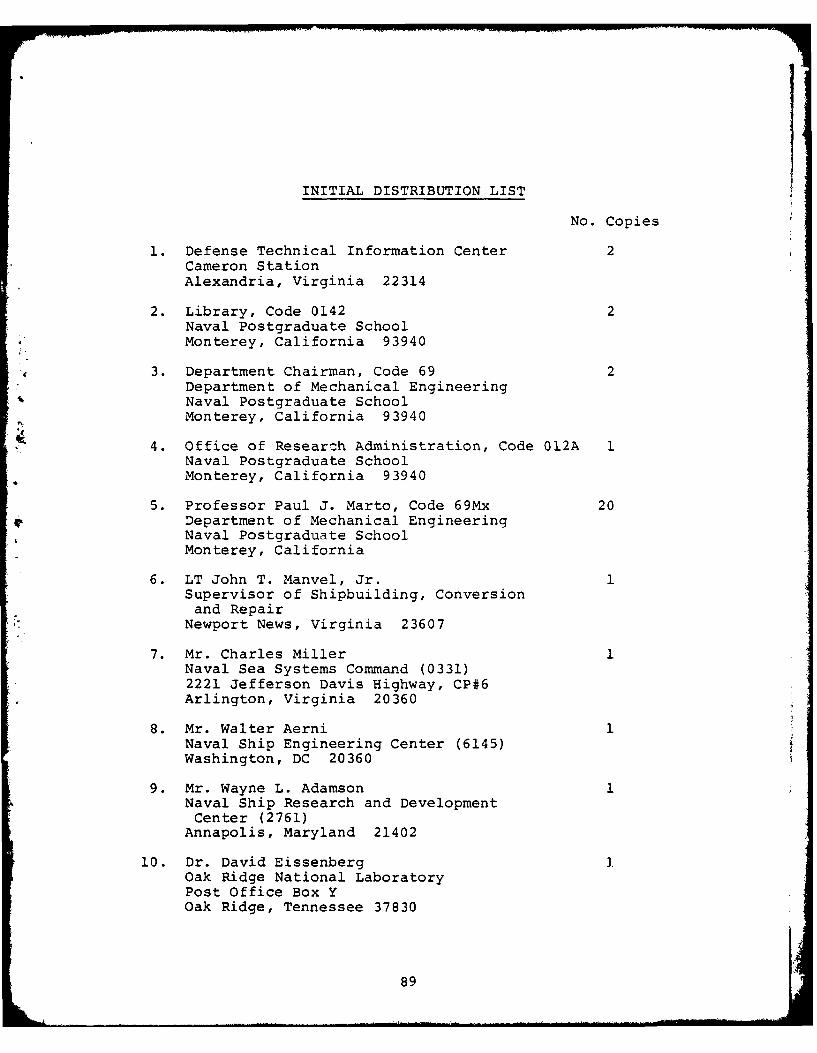
INITIAL DISTRIBUTION LIST
No. Copies
1. Defense Technical Information Center 2Cameron StationAlexandria, Virginia 22314
2. Library, Code 0142 2Naval Postgraduate School
4 Monterey, California 93940
3. Department Chairman, Code 69 2Department of Mechanical EngineeringNaval Postgraduate SchoolMonterey, California 93940
4. Office of Researzh Administration, Code 012A 1Naval Postgraduate SchoolMonterey, California 93940
5. Professor Paul J. Marto, Code 69Mx: 20Department of Mechanical EngineeringNaval Postgraduate SchoolMonterey, California
6. LT John T. Manvel, Jr. 1Supervisor of Shipbuilding, Conversionand Repair
* Newport News, Virginia 23607
7. Mr. Charles Miller 1Naval Sea Systems Command (0331)2221 Jefferson Davis Highway, CP#6
* Arlington, Virginia 20360
8. Mr. Walter Aerni 1Naval Ship Engineering Center (6145)Washington, DC 20360
9. Mr. Wayne L. Adamson 1* Naval Ship Research and Development
Center (2761)Annapolis, Maryland 21402
10. Dr. David Eissenberg 1.Oak Ridge National LaboratoryPost Office Box YOak Ridge, Tennessee 37830
89
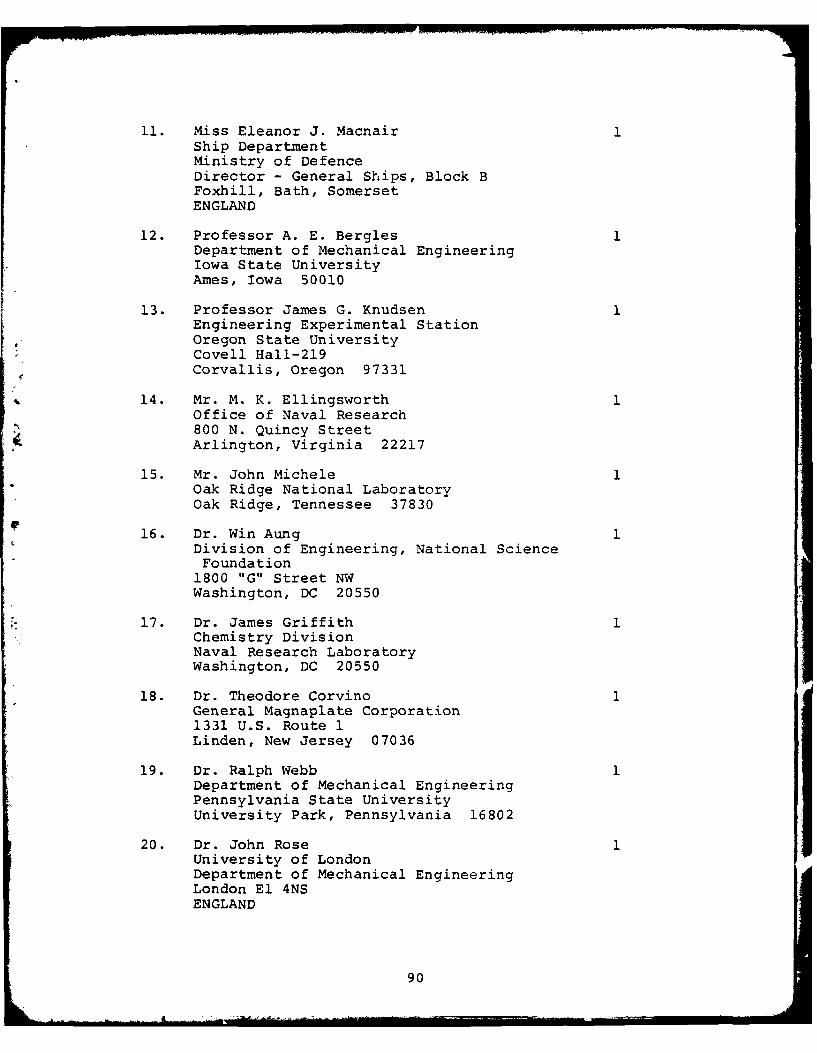
11. Miss Eleanor J. MacnairShip DepartmentMinistry of DefenceDirector - General Ships, Block BFoxhill, Bath, SomersetENGLAND
12. Professor A. E. BerglesDepartment of Mechanical EngineeringIowa State UniversityAmes, Iowa 50010
13. Professor James G. KnudsenEngineering Experimental StationOregon State UniversityCovell Hall-219Corvallis, Oregon 97331
14. Mr. M. K. EllingsworthOffice of Naval Research800 N. Quincy StreetArlington, Virginia 22217
15. Mr. John MicheleOak Ridge National LaboratoryOak Ridge, Tennessee 37830
16. Dr. Win AungDivision of Engineering, National ScienceFoundation1800 "G" Street NWWashington, DC 20550
17. Dr. James GriffithChemistry DivisionNaval Research LaboratoryWashington, DC 20550
18. Dr. Theodore CorvinoGeneral Magnaplate Corporation1331 U.S. Route 1Linden, New Jersey 07036
19. Dr. Ralph WebbDepartment of Mechanical EngineeringPennsylvania State UniversityUniversity Park, Pennsylvania 16802
20. Dr. John RoseUniversity of LondonDepartment of Mechanical EngineeringLondon El 4NSENGLAND
90

21. LT Kevin Perkins, USN 2U.S. Naval Ship Repair FacilityP.O. Box 8FPO Seattle, Washington 98762
22. Dr. Garret Vanderplaats, Code 69VdDepartment of Mechanical EngineeringNaval Postgraduate SchoolMonterey, California 93940
23. Dr. J. W. WestwaterDepartment of Chemical EngineeringUniversity of IllinoisUrbana, Illinois 61801
9
91