an experimental study of composite effect on the behaviour
TRANSCRIPT

12th International Conference on Advances in Steel-Concrete Composite Structures (ASCCS 2018) Universitat Politècnica de València, València, Spain, June 27-29, 2018
Doi: http://dx.doi.org/10.4995/ASCCS2018.2018.6952
2018, Universitat Politècnica de València
An experimental study of composite effect on the behaviour of beam-column joints subjected to impact load
K. Chena, K. H. Tan a* aSchool of Civil and Enviromental Engineering, Nanyang Technological University, Singapore *corresponding author, e-mail address: [email protected]
Abstract This paper presents an experimental study on structural behaviour of composite beam-column joints under a middle column removal scenario. Specimens were subjected to impact loads from an MTS drop-weight testing machine. Two joints with welded unreinforced beam flange and bolted web connections were designed per AISC 360-10. One of the beam-column joints had a thicker composite slab. The joints were restrained by pinned supports at two beam ends, which were connected to rigid A-frames to represent boundary conditions from adjacent structures. Test results indicated that the composite slab significantly affected the impact force due to an increase of inertia. However, other structural responses (especially displacement of the middle column) decreased due to increase of stiffness contributed by the thicker composite slab. The finding was that increasing thickness of composite slab can increase the resistance of composite joint significantly due to increased composite effect. More experimental studies were conducted to investigate other types of joints.
Keywords: Composite slab; beam-column joints; impact.
1. Introduction Extensive research efforts were concentrated
on mitigation of progressive collapse of building structures since partial collapse of the Ronan point compartment in the U.K. occurred in 1967. Furthermore, the disastrous terrorist attack on the World Trade Centre on September 11th 2001 hastened the release of several commonly-used technical documents on mitigating progressive collapse, including UFC-4-023 [1] and GSA [2] guidelines. In these documents, a column removal scenario was proposed to simulate the initial damage caused by abnormal loading conditions, which was effective in blast-induced damage to columns tested by Karns et al. [3]. Several research studies were conducted on bare steel beam-column joints in structural frames under column removal scenarios, including both quasi-static [4] and dynamic [5-9] tests. However, tests considering the contribution of composite slab were limited to quasi-static [10-12] loads, although progressive collapse is a dynamic process in nature. In this study, two specimens with welded unreinforced beam flange and bolted web (WUF-B) connections
were tested subjected to impact loads. The contribution of composite slabs to the resistance of beam-column joints was also investigated.
2. Experimental programme Impact loads were applied to the specimens
using an MTS drop-weight testing machine in Protective Engineering Laboratory in Nanyang Technological University [13]. Fig. 1 shows three-dimensional perspective of the test set-up. Two pinned supports at both ends of the specimens were used to represent idealised boundary conditions from adjacent structures. One strain-gauged horizontal short column stub served as a load cell and allowed external forces to be measured.
The test programme belongs to a research project which consists of different joints subjected to impact loads. In this paper, two of WUF-B joints are presented. In the project, a prototype composite steel frame structure was designed against gravity loads based on Eurocode 4 [14] and scaled down using a factor of 0.5 due to limited test space. The joints were
905

Chen, K. and Tan, K. H.
extracted from the frame and designed per AISC 360-10 [15] One steel column was ‘forcibly removed’ as prescribed by UFC 4-023-03 [1]. The detailed information of these two specimens is summarised in Table 1. Figs. 2 and 3 show the detailing and layout of strain gauges of these two specimens, respectively. The only difference between the two joints was the slab thickness so that composite slab effect can be investigated. Close to the connection, strain gauges were attached to each component including concrete, profiled sheeting, reinforcement and beam flanges to monitor the development of strain.
Fig. 1. Test set-up in three-dimensional perspective.
Table 1. Summary of test specimens
ID Slab
thickness (mm)
Drop-weight (kg)
Height (m)
C75W-M770H3 75 770 2.998
C100W-M770H3 100 770 2.996
Nomenclature: C – Composite; W – WUF-B; M - Mass of impact hammer, kg; H – Drop-height, m
(a)
(b)
Fig. 2. Detailing and layout of strain gauges of C75W-M770H3: (a) Front view; (b) Section 1-1.
2018, Universitat Politècnica de València 906

Chen, K. and Tan, K. H.
2018, Universitat Politècnica de València
(a)
(b)
Fig. 3. Detailing and layout of strain gauges of C100W-M770H3: (a) Front view; (b) Section 1-1.
3. Material property Uniform I-shaped beams and columns were
made of Grade S355 steel. Grade S275 fin plates were 6 mm thick. Mild steel reinforcement in the composite slab had a diameter of 6 mm and was placed along both the transverse and longitudinal directions at 170 mm spacing. For profiled sheeting, re-entrant steel metal sheeting was employed. Standard concrete cylinder (150 mm diameter and 300 mm length) tests were also conducted. Average compressive strength was 50.6 MPa with a standard deriviation of 5.4 MPa.
4. Test results and discussions 4.1 Development of impact force and displacement
Fig. 4(a) shows the development of impact force of both specimens. The first peak impact force of C100W-M770H3 was 1373.1 kN, greater than 1188.9 kN of C75W-M770H3.
Since the same impact hammer was used, the peak impact force was directly dominated by the inertia of the test specimens. Specimen C100W-M770H3 had a thicker concrete slab, which led to a greater mass and inertia as well. However, the ensuing damped periods of vibration of both specimens were generally similar, although C75W-M770H3 had slightly greater value. In contrast, displacements of the middle column stub for the two joints show a substantial difference in Fig. 4(b). Although the impact force of C100W-M770H3 was greater, the peak and residual displacements were much smaller than those of C75W-M770H3 due to contribution of the thicker concrete slab, indicating that the former had greater resistance. The reason was that C100W-M770H3 had a greater lever arm to resist bending moment induced by the concentrated impact force, although reinforcing bars and beams were the same as those of C75W-M770H3.
0.00 0.01 0.02 0.03 0.04 0.050
200
400
600
800
1000
1200
1400 C75W-M770H3 C100W-M770H3
Load
(kN
)
Time (s) (a)
0.00 0.05 0.10 0.150
20
40
60
80
100 C75W-M770H3 C100W-M770H3
Dis
plac
emen
t (m
m)
Time (s) (b)
Fig. 4. Comparison of specimens C75W-M770H3 and C100W-M770H3: (a) Impact force; (b) Displacement of the middle column stub.
907

Chen, K. and Tan, K. H.
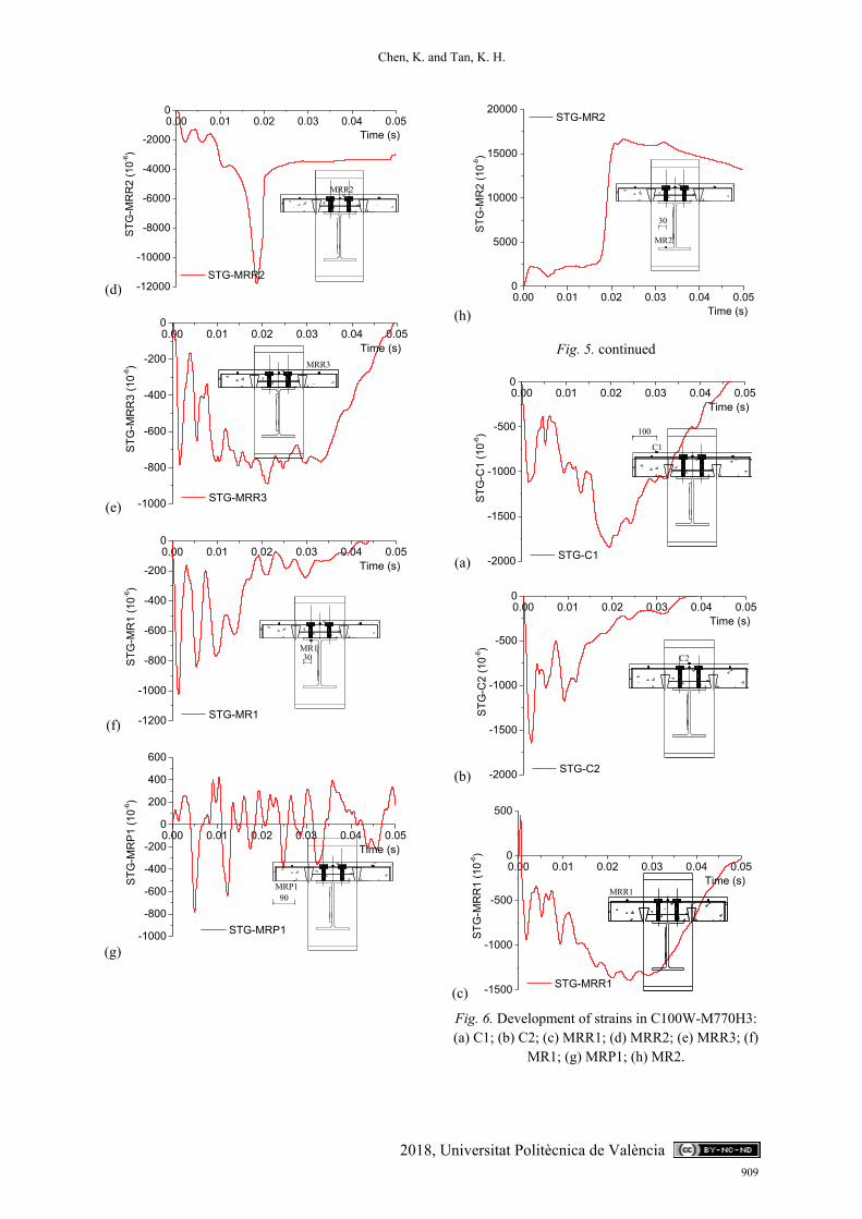
4.2 Strain and strain rate Figs. 5 and 6 show the development of strains
recorded by strain gauges attached to various locations of the joints. To facilitate the understanding of these figures, the locations of the strain gauges in Figs. 2 and 3 were represented in each figure. Based on the yield strength and modulus of elasticity, the respective yield strains of reinforcing bars, profiled sheeting and I-beam were 1824 µε, 1980 µε and 2146 µε.
In C75W-M770H3, strains of the top concrete surface were negative as shown in Fig. 5(a) at the centreline and Fig. 5(b) at section 1-1, indicating that the concrete slab was in compression. It can be further validated by strains of the reinforcing bars in Figs. 5(c) to (e). Strains of side reinforcing bars MRR1 (Fig. 5(c)) and MRR3 (Fig. 5(e)) were also negative. Although the middle reinforcing bar was discontinuous, it could bear against the middle column flange so that compressive strain (MRR2) was also observed as shown in Fig. 5(d). Strain gauges MR1 and MRP1 were attached to the top beam flange and profiled sheeting, respectively. They were at a similar height at the cross-section of the connection. Both readings were negative in Figs. 5(f) and (g) so that they were subjected to compression, indicating that neutral axis of the cross-section lay in the beam web. The bottom beam flange (MR2 in Fig. 5(h)) was subjected to tension, which was large enough to induce plastic strain. Such plastic strain was the source of residual plastic displacement as shown in Fig. 4(b). It should be noted that the front side of the concrete slab (the left side at each cross-section) flipped upwards due to debonding between the concrete and the profiled sheeting underneath. It was attributed to weakening of the concrete cross-section due to the re-entrant profiled sheeting. This phenomenon was not observed on the opposite side (the right side at each cross-section) because concrete was restrained by a steel plate, which served as a target for the displacement laser sensor. Therefore, reading of the strain gauge MRR1 was different from that of MRR3 located on the opposite side. The reading of the strain gauge MRP1 also vibrated due to the debonding.
Similarly, the top concrete slab in C100W-M770H3 was subjected to compression as shown in Fig. 6(a) at the centreline and Fig. 6(b) at section 1-1. Side reinforcing bars (MRR1 and
MRR3) were also subjected to compression as shown in Figs. 6(c) and (e), respectively. Discontinuous middle rebar (MRR2) was subjected to compression as shown in Fig. 6(d). However, the top beam flange (MR1 in Fig. 6(f)) and profiled sheeting (MRP1 in Fig. 6(g)) were subjected to tension as well as the bottom beam flange (MR2 in Fig. 6(h)), indicating that neutral axis of the composite cross-section lay in the composite slab. Since the slab was thicker than that of C75W-M770H3, weakening caused by the re-entrant profiled sheeting was not as severe. Flip-over of composite slab at the front side was not observed. Therefore, readings of strain gauges MRR1 and MRR3 were similar.
(a)
(b)
(c)
Fig. 5. Development of strains in C75W-M770H3: (a) C1; (b) C2; (c) MRR1; (d) MRR2; (e) MRR3; (f)
MR1; (g) MRP1; (h) MR2.
0.00 0.01 0.02 0.03 0.04 0.05
-1200
-1000
-800
-600
-400
-200
0
STG
-C1
(10-6
)
Time (s)
STG-C1
0.00 0.01 0.02 0.03 0.04 0.05
-2500
-2000
-1500
-1000
-500
0
STG
-C2
(10-6
)
Time (s)
STG-C2
0.00 0.01 0.02 0.03 0.04 0.05
-800
-600
-400
-200
0
200
400
600
800
1000
STG
-MR
R1
(10-6
)
Time (s)
STG-MRR1
2018, Universitat Politècnica de València 908
Chen, K. and Tan, K. H.
2018, Universitat Politècnica de València
(d)
(e)
(f)
(g)
(h)
Fig. 5. continued
(a)
(b)
(c)
Fig. 6. Development of strains in C100W-M770H3: (a) C1; (b) C2; (c) MRR1; (d) MRR2; (e) MRR3; (f)
MR1; (g) MRP1; (h) MR2.
0.00 0.01 0.02 0.03 0.04 0.05
-12000
-10000
-8000
-6000
-4000
-2000
0ST
G-M
RR
2 (1
0-6)
Time (s)
STG-MRR2
0.00 0.01 0.02 0.03 0.04 0.05
-1000
-800
-600
-400
-200
0
STG
-MR
R3
(10-6
)
Time (s)
STG-MRR3
0.00 0.01 0.02 0.03 0.04 0.05
-1200
-1000
-800
-600
-400
-200
0
STG
-MR
1 (1
0-6)
Time (s)
STG-MR1
0.00 0.01 0.02 0.03 0.04 0.05
-1000
-800
-600
-400
-200
0
200
400
600
STG
-MR
P1 (1
0-6)
Time (s)
STG-MRP1
0.00 0.01 0.02 0.03 0.04 0.050
5000
10000
15000
20000
STG
-MR
2 (1
0-6)
Time (s)
STG-MR2
0.00 0.01 0.02 0.03 0.04 0.05
-2000
-1500
-1000
-500
0
STG
-C1
(10-6
)
Time (s)
STG-C1
0.00 0.01 0.02 0.03 0.04 0.05
-2000
-1500
-1000
-500
0
STG
-C2
(10-6
)
Time (s)
STG-C2
0.00 0.01 0.02 0.03 0.04 0.05
-1500
-1000
-500
0
500
STG
-MR
R1
(10-6
)
Time (s)
STG-MRR1
909

Chen, K. and Tan, K. H.
(d)
(e)
(f)
(g)
(h)
Fig. 6. continued.
The peak strain rates were obtained by differentiating the strains with respect to time. All the strain rates were in the order of magnitude of 1 s-1. Strain rates of the bottom flange in tension exceeded 5 s-1 and were marked in bold fonts. A maximum value of 7.34 s-1 was observed in the bottom beam flange of C75W-M770H3. Strain rate in the concrete crushing zone was around -2 s-1 for both specimens.
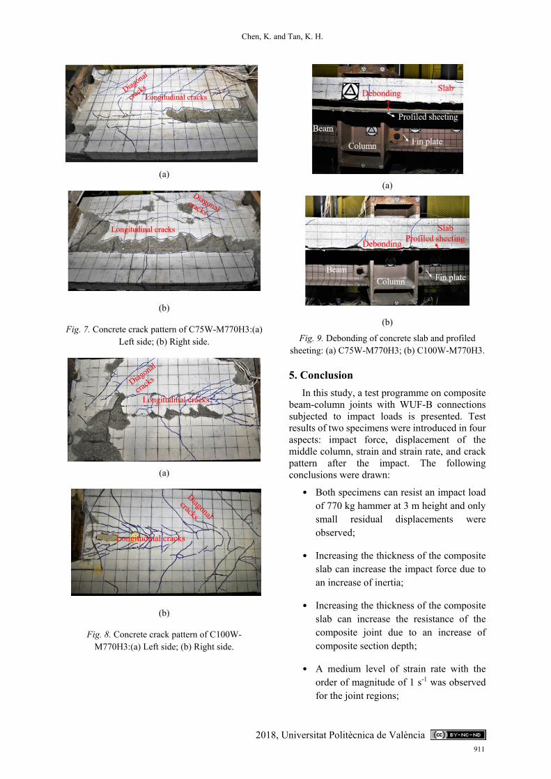
4.3 Failure mode Unlike previous tests on fin plate connections
conducted by the authors [13], complete fracture of the composite joint was not observed in both specimens since they could resist the impact loads. Failure of C75W-M770H3 concentrated in concrete slabs as shown in Figs. 8(a) and (b), for each side respectively. Similarly, crack patterns for each slab side of C100W-M770H3 are shown in Figs. 9(a) and (b), respectively. For both specimens, two types of concrete cracks were observed: longitudinal and diagonal cracks. The longitudinal cracks ran along the re-entrant profile of the sheeting. They were caused by longitudinal shear, resulting from weakening of the concrete cross-section. The diagonal cracks were attributed to a punching-shear effect of the concrete slab as it was subjected to a concentrated dynamic load. All the steel components, including bolts, fin plates, top and bottom beam flanges, steel profiled sheeting and reinforcing bars did not fail in fracture (C75W-M770H3 in Fig. 9(a) and C100W-M770H3 in Fig. 9(b), respectively). Most of them remained elastic, except that the middle reinforcing bar yielded in compression and the bottom beam flange yielded in tension.
0.00 0.01 0.02 0.03 0.04 0.05
-20000
-16000
-12000
-8000
-4000
0ST
G-M
RR
2 (1
0-6)
Time (s)
STG-MRR2
0.00 0.01 0.02 0.03 0.04 0.05
-1800
-1600
-1400
-1200
-1000
-800
-600
-400
-200
0
STG
-MR
R3
(10-6
)
Time (s)
STG-MRR3
0.00 0.01 0.02 0.03 0.04 0.05
-800
-600
-400
-200
0
200
400
600
800
1000
STG
-MR
1 (1
0-6)
Time (s)
STG-MR1
0.00 0.01 0.02 0.03 0.04 0.05
-200
0
200
400
600
800
STG
-MR
P1 (1
0-6)
Time (s) STG-MRP1
0.00 0.01 0.02 0.03 0.04 0.050
5000
10000
15000
20000
STG
-MR
2 (1
0-6)
Time (s)
STG-MR2
2018, Universitat Politècnica de València 910
Chen, K. and Tan, K. H.
2018, Universitat Politècnica de València
(a)
(b)
Fig. 7. Concrete crack pattern of C75W-M770H3:(a) Left side; (b) Right side.
(a)
(b)
Fig. 8. Concrete crack pattern of C100W-M770H3:(a) Left side; (b) Right side.
(a)
(b)
Fig. 9. Debonding of concrete slab and profiled sheeting: (a) C75W-M770H3; (b) C100W-M770H3.
5. Conclusion In this study, a test programme on composite
beam-column joints with WUF-B connections subjected to impact loads is presented. Test results of two specimens were introduced in four aspects: impact force, displacement of the middle column, strain and strain rate, and crack pattern after the impact. The following conclusions were drawn:
• Both specimens can resist an impact load of 770 kg hammer at 3 m height and only small residual displacements were observed;
• Increasing the thickness of the composite slab can increase the impact force due to an increase of inertia;
• Increasing the thickness of the composite slab can increase the resistance of the composite joint due to an increase of composite section depth;
• A medium level of strain rate with the order of magnitude of 1 s-1 was observed for the joint regions;
911

Chen, K. and Tan, K. H.
• Major cracks in the composite slab governed failure mode of both specimens.
References: [1] UFC 4-023-03. Design of buildings to resist
progressive collapse. Washington DC; 2013 [2] GSA 2013. Alternate path analysis and design
guidelines for progressive collapse resistance. Washington DC; 2013
[3] Karns JE, Houghton DL, Hong JK, Kim J. Behavior of varied steel frame connection types subjected to air blast, debris impact, and/or post-blast progressive collapse load conditions. Austin; 2009
[4] Yang B, Tan KH. Experimental tests of different types of bolted steel beam–column joints under a central-column-removal scenario. Engineering Structures 2013;54:112-130.
[5] Tyas A, Warren JA, Stoddart EP, Davison JB, Tait SJ, Huang Y. A methodology for combined rotation-extension testing of simple steel beam to column joints at high rates of loading. Experimental Mechanics 2012;52:1097-1109.
[6] Rahbari R, Tyas A, Buick DJ, Stoddart EP. Web shear failure of angle-cleat connections loaded at high rates. Journal of Constructional Steel Research 2014;103:37-48.
[7] Liu C, Tan KH, Fung TC. Dynamic behaviour of web cleat connections subjected to sudden column removal scenario. Journal of Constructional Steel Research 2013;86:92-106.
[8] Grimsmo EL, Clausen AH, Langseth M, Aalberg A. An experimental study of static and dynamic behaviour of bolted end-plate joints of Steel. International Journal of Impact Engineering 2015;85:132-145.
[9] Grimsmo EL, Clausen AH, Aalberg A., Langseth M. A numerical study of beam-to-column joints subjected to impact. Engineering Structures 2016;120:103-115.
[10] Kuhlmann U, Rölle L, Jaspart JP, Demonceau JF. Robustness-Robust structures by joint ductility. COST Action C26 workshop in Pragua-Urban Habitat constructions under catastrophic events. Prague; 2007.
[11] Yang B, Tan KH. Behavior of Composite Beam-Column Joints in a Middle-Column-Removal Scenario: Experimental Test. Journal of Structural Engineering 2014;140(2):04013045.
[12] Guo L, Gao S, Wang Y, Zhang S. Tests of rigid composite joints subjected to bending moment combined with tension. Journal of Constructional Steel Research 2014;95:44-55.
[13] Chen K, Tan K, Yang B. An experimental study of composite beam-column joints subjected to impact loads. Copenhagen; 2017.
[14] BS EN 1994-1-1. Design of composite steel and concrete structures—Part 1-1: General rules and rules for buildings. London; 2004.
[15] ANSI/AISC 360-10. Specification for Structural Steel Buildings. Chicago; 2010.
2018, Universitat Politècnica de València 912