an experimental and theoretical investigation on … experimental and theoretical investigation on...
TRANSCRIPT

13
Iranian Journal of Chemical Engineering Vol. 6, No. 3 (Summer), 2009, IAChE
An Experimental and Theoretical Investigation on Thermal
Performance of a Gas-Liquid Thermosyphon Heat Pipe Heat Exchanger in a Semi-Industrial Plant
H. Zare Aliabadi1,2∗, H. Ateshi2, S. H. Noei3 and M. Khoram2
1- Department of Chemical Engineering, Islamic Azad University, Shahrood Branch, Shahrood, I. R. Iran. 2- Department of Chemical Engineering, University of Sistan and Baluchestan, Zahedan, I. R. Iran.
3- Department of Chemical Engineering, Ferdowsi University of Mashhad, Mashhad, I. R. Iran.
Abstract Waste heat recovery is very important, because it not only reduces the expenditure of heat generation, but also it is of high priority in environmental consideration, such as reduction in greenhouse gases. One of the devices used in waste heat recovery is heat pipe heat exchanger. An experimental and theoretical research is carried out to investigate heat performance of an air to water thermosyphon heat pipe heat exchanger according to ε-NTU method. The experiments were done according to the following procedure: cold water with 0.1kg/s flows through the condensation section and hot air in a closed cycle is blown into the evaporation section. A blower with varying frequency of current turns in the mass flow rate between 0.14-0.6 kg/s and a temperature range of 125-225°C. The results of the experiments show that as the ratio of h cC C rises, the rate of heat transfer goes up. The efficiency of the heat pipe heat exchanger remains constant as the temperature of the hot stream goes up, but the amount of heat transferred increases. Keywords: Thermosyphon heat pipe heat exchanger, ε-NTU method, In-line configuration
∗ Corresponding author: [email protected]
1- Introduction Heat recovery, one method of energy conservation, can be successfully imple-mented when the investment cost of the additional equipment required is acceptably low. Thermosyphon based heat exchangers are very simple devices that can be used to
heat transfer between two fluid phases. Features include no cross-contamination between streams, no moving parts, com-pactness and no need for any external power supply. Their heat transfer coefficient in the evaporator and condenser zones is 103-105 w/m2k; and heat pipe thermal resistance

Zare Aliabadi, Ateshi, Noei, Khoram
14 Iranian Journal of Chemical Engineering, Vol. 6, No. 3
is 0.01-0.03 k/w, therefore leading to smaller area and mass of heat exchangers [1]. Appropriate performance of a heat pipe heat exchanger "HPHE" depends on many parameters, such as hot air mass flow rate, inlet air temperature, filling ratio and pressure drop across tube bank of heat pipes. Since the mid-1970's, researches dealing with heat pipe heat exchangers have steadily increased in number. In this section, a brief review of some of the experimental and theoretical research conducted is presented. Azad and Geoola [2] applied the ε-NTU model for gravity-assigned air-to-air heat pipe heat exchanger. They developed a new correlation for condensing water vapor on vertical carbon –steel and determined that the external thermal resistances in those cases limit the performance of heat pipe heat exchanger where the thermosyphon are operating below the sonic limit. Zhongliang Liu et al. [3, 4] have studied heat transfer characteristics of "HPHE" with latent heat storage. They have reported a new thermal storage system and a heat pipe heat exchanger with latent heat storage. The new system may operate in three basic different operation modes, the charging only, the discharging only and the simultaneous charging/discharging modes. In addition, they have studied the performance of the simultaneous charging/discharging operation modes of the heat pipe heat exchanger. The experimental results on the charging only mode and the discharging only mode of the system show that the new device performs the designed functions very well. It can both store and release the thermal energy efficiently, however, the device can be used as a conventional system in which the
charging and discharging are operated independently. Also, the results for the simultaneous charging/discharging mode were unknown. Shah and Giovannelli [5] studied heat pipe heat exchanger performance from a comparative point of view. The performance of a single HPHE was modelled using both LMTD and the ε-NTU method. The thermal resistances were determined using many existing correlations and the results compared. In addition, they have presented a good correlation for predicting pressure drop across tube bundle of HPHE. Tan and Liu [6] have used the ε-NTU method to analyze an air-to-air heat pipe heat exchanger. They also have presented an equation to determine the optimum position separating a heat pipe into an evaporator, and condenser regions in a heat pipe heat exchanger were formulated by minimizing the total thermal resistance of the heat path. Their present results indicated that the optimal position of the partition plate of a heat pipe heat exchanger is the middle of HPHE. Nevertheless, it is not necessarily in the middle of it, because its position depends upon the relative magnitude of the flow rates of the hot and cold fluids. When the difference in flow rate of the two fluids is small, the optimal position is quite near the middle, but when the difference is large the position of the partition plate should be optimized. Wadowski and et al. [7] carried out an experimental study to investigate the performance of an air-to-air thermosyphon –based heat exchanger utilizing R-22 as the working fluid under different operating conditions. They have investigated thermal performance of HPHE, where the mass flow rate of hot air was limited to a range of 0.06

An Experimental and Theoretical Investigation on Thermal Performance of a Gas-Liquid Thermosyphon Heat Pipe Heat Exchanger in a Semi-Industrial Plant
Iranian Journal of Chemical Engineering, Vol. 6, No. 3 15
to 0.28kg/s and the temperature of hot air up to 70°C. Yang et al. [8] have built a thermosyphon heat pipe heat exchanger for recovery of the gas heat emitted from automobile exhausts, and investigated the thermal performance of "THE". Noie and Majidian [9] have built a "THE" for recovery of heat waste in hospitals and laboratories. The test rig used in their research consists of eight individual heat pipes and the following characteristics: three rows of heat pipe, methanol as a working fluid and heat pipes in a staggered equilateral triangle arrangement of 45 mm center. Since methanol is used as working fluid, the application of this heat pipe heat exchanger is limited to a range of 15-55°C. In addition, since the numbers of heat pipes used for manufacturing the exchanger are eight, the duty of heat transfer is limited to 150w, at least. In addition, Noie [10] has carried out an experimental study of the performance of an air-to-air thermosyphon-based heat exchanger utilizing water as working fluid to investigate its behavior under different operating conditions. Song Lin et al. [11] have presented a design method using CFD simulation of the dehumidification process with a heat pipe heat exchanger. Their studies illustrate that the CFD modeling is able to predict the thermal performance of the dehumidification solution with HPHE. The simulation results in this paper only reflect the overall performance of the system at different operating conditions. The details of the thermal characteristics and design parameters of the system cannot be published in this paper. The operating parameters used in this paper are: the inlet temperature of air 35-50°C, the inlet flow rate 4-8lit/s. The
predicted results also indicate that the heat pipe unit can be further optimized to achieve similar or better heat transfer performance than the auxiliary condenser. However, the auxiliary condenser is necessary to maintain the temperature difference between the two ends of the heat pipe unit. In this research, we have investigated the effects of various parameters such as the heat capacity ratio of high- and low-temperature fluid streams "Ce/Cc", the inlet hot air temperature and the mass flow rate or the inlet hot air velocity on thermal performance of a gas-liquid "THE", experimentally and theoretically. In order to investigate the parameters affecting hydrody-namics and thermal performance of Thermosyphon heat pipe heat exchanger (THE), a semi industrial pilot was designed. The mass flow rate of hot air varies in the range of 0.15-0.55kg/s and the inlet hot air temperature controls at five quantities as 100,125,150,175,200°C.
2- Theory The analysis of the heat transfer aspects of HPHE's based on the heat transfer rate equation obtained by an energy balance of the heat exchanger:
h cQ U.S(T T )= − (1)
There are two main approaches used in the design of a HPHE:
1) The Log-mean temperature difference model (LMTD)
2) The effectiveness-number of transfer units model (ε-NTU)
2.1- ε-NTU method The ε-NTU method based on the heat exchanger effectiveness, ε, which is defined

Zare Aliabadi, Ateshi, Noei, Khoram
16 Iranian Journal of Chemical Engineering, Vol. 6, No. 3
as the ratio of the actual heat transfer in a heat exchanger to the heat transfer that would have occurred in a heat exchanger with an infinite surface. The exit temperature of the low-temperature fluid would equal the inlet temperature of the high-temperature fluid. Therefore, the effectiveness can be defined as [12]:
),,(min
),,(),,(min
),,(
max incTinhTCincToutcTcC
incTinhTCouthTinhThC
−−
=−
−==ε
(2) Applying conservation of energy, the general exponential function for a counter-flow heat exchanger is:
)]maxmin1(
minexp[
maxmin1
)]maxmin1(
minexp[1
CC
CtStU
CC
CC
CtStU
−−−
−−=ε (3)
The ratio minC
tStU defines, as the number of
transfer units (NTU),
minCtStU
NTU = (4)
min)(min pCmC = (5)
cpcmcCepcmeC )(,)( == (6)
Where, the heat capacities of fluid in the evaporator and condenser sections of a heat pipe heat exchanger are e cC ,C , respectively. Therefore, effectiveness can be calculated by the following correlations:
cCeCifincTinhTincToutcT
<−−
= ,,,,,ε (7)
cCeCifincTinhTouthTinhT
>−
−= ,
,,,,ε (8)
Due to phase change, the maximum heat capacity is several orders of magnitude larger than the minimum heat capacity. Therefore, the heat capacity ratio between minimum and maximum heat capacities are equal to zero
( min 0max
≈CC ) and the expressions for
effectiveness are presented as follows:
)exp(1 NTU−−=ε (9) The effectiveness of the evaporator and condenser sections of the heat pipe heat exchanger can be defined as:
)exp(1 eNTUe −−=ε (10)
)exp(1 cNTUc −−=ε (11)
Where, eC
eSeUeNTU .= and
cCcScU
cNTU .=
These correlations are defined for a single row of pipes. The effectiveness of heat pipe heat exchanger with n rows of pipes is as follows:
nene )1
1(1 εε −−= (12)
ncnc )
11(1 εε −−= (13)
The least overall effectiveness of heat pipe heat exchanger is obtained by the following correlations:

An Experimental and Theoretical Investigation on Thermal Performance of a Gas-Liquid Thermosyphon Heat Pipe Heat Exchanger in a Semi-Industrial Plant
Iranian Journal of Chemical Engineering, Vol. 6, No. 3 17
neeC
cC
nc
o
εε
ε
+
=
1
1 If cCeC > (14)
nccC
eC
ne
o
εε
ε
+
=
1
1 If ce CC < (15)
2.2- Determination of the overall heat transfer coefficient To determine the overall heat transfer coefficient, the heat transfer is modelled as a thermal resistance network shown in Fig.1.
1 1 1 1,( )
1, ( )
R Rf c hpUS U S U S hsc c o ch hR f h hso h
= = = + +η
+ + η
(16)
)ln(21
)(1[1
iDoD
eLwkhhsohShU πη += (17)
hhsohR )(1
η= , )ln(21
, iDoD
eLwkhwR π=
(18) In this research, it is assumed that fouling resistances due to corrosion or oxidation are negligible and resistance terms that occurred due to heat transfer through the liquid saturated wick are negligible, too. For the condenser section, we have:
)ln(21
)(1[1
iDoD
cLwkchscScU π+= (19)
chscR )(1= , )ln(2
1,iDoD
cLwkcwR π=
(20)
Figure 1. Thermal resistance network of a THPHE
Tν,e Tν,c rw
ri
ro
Rw,e
Rf, e
Re
Rwi,e
Ri, e Rν
Rc
Ri, c
Rwi,c
Rw,c
Rf,
Tc Th
Evaporator section Condenser section

Zare Aliabadi, Ateshi, Noei, Khoram
18 Iranian Journal of Chemical Engineering, Vol. 6, No. 3
3- Experimental set up and procedure In order to investigate the parameters affecting the hydrodynamics and thermal performance of Thermosyphon heat pipe heat exchanger (THPHE), a semi industrial pilot based on Fig.2 is designed. This model consists of the following parts: Thermosyphon heat pipe heat exchanger, air channels, Rota meter, a centrifugal blower, electrical heaters, thermometers, electrical board, fan speed regulator, orifice and manometer. The test rig has two sections, top and bottom. The top section is the condensation part of the HPHE in which cooled water is drowned into it by a pump with a constant flow rate (7lit/min) at about 17°C. It then goes out from the top section after gaining the pipe's heat by passing above them. The water flow is regulated by Rota meter. The bottom section is the evaporation part of the HPHE. The bottom duct is straight and forms a closed loop. A centrifugal blower and 90 electrical heaters are installed in the duct to circulate hot air through the evaporator section. In the bottom duct, mass
flow rate varies by changing the input frequency to the blower in the range of (20-70HZ), therefore the mass flow rate varies in the range of (0.15-0.55kg/s). The experimental data has been obtained by repeating the tests three times. Thermosy-phon heat pipe heat exchanger (THPHE) module is composed of 6(rows)*15(columns) copper pipes with aluminum plate fins with dimensions of 130cm (height)*47cm (width)*20cm (depth) which have been filled with water at a filling ratio of 30%, 50% and 70%. The density and thickness of the fins are 300 fin/m and 0.4mm, respectively. The used exchanger has the following characteristics mentioned in Table 1 and Fig.3. The manufactured THPHE, which is fixed to the channel from the top and bottom, is placed inside the channel and is encompassed with cold water and hot air. Pressure drop between the inlet and outlet of the THPHE is measured by inclined manometer. The inlet hot air temperature is controlled at five quantities as 100,125,150,175,200°C.
Figure 2. Photo of pilot plant

An Experimental and Theoretical Investigation on Thermal Performance of a Gas-Liquid Thermosyphon Heat Pipe Heat Exchanger in a Semi-Industrial Plant
Iranian Journal of Chemical Engineering, Vol. 6, No. 3 19
Table 1. Specifications of thermosyphon heat pipe heat exchanger
Fin Aluminum plate Thickness 0.4 mm Density 300 fin/m
Configuration In-line L TS S 30mm= =
Num. of heat pipe rows =NL 6, =NT 15
Total Num. of heat pipes =Ntotal 90
Material and working fluid of heat pipe Copper-distillated water
Figure 3. Dimensions of the "THPHE"
4- Results and discussion The effects of various parameters such as the heat capacity ratio of high- and low-temperature fluid streams "Ce/Cc", the inlet hot air temperature, and the mass flow rate or the inlet hot air velocity on thermal performance of a gas-liquid "THE" have been investigated, experimentally and theore-tically. The following results have been obtained. 4.1- Heat capacities ratio effect (Ce/Cc) Heat capacities ratio is one of the most important factors influencing the effec-tiveness and the rate of heat transfer. The effectiveness and the rate of transferred heat
vs. Ce/Cc is shown in Fig.4 for all inlet hot air temperature (Te,i). The heat capacity ratio of high-and low-temperature fluid streams affects the effectiveness and the rate of heat transfer of "THE". When the heat capacity ratio of high-and low-temperature fluid streams is higher than unity the effectiveness increases due to the ability of the fluid streams to release and absorb more heat. At "Ce=Cc" the effectiveness is minimum because of the release, and the absorption heat is less. At "Ce<Cc", the effectiveness decreases by increasing the ratio of Ce/Cc, because the sensible heat of the high-temperature fluid stream is less than the low-temperature fluid stream.
50 Cm
50 Cm
10 Cm
20 Cm 47 Cm
110 Cm
Condensation ti
Adiabatic section
Evaporation ti

Zare Aliabadi, Ateshi, Noei, Khoram
20 Iranian Journal of Chemical Engineering, Vol. 6, No. 3
0.4
0.45
0.5
0.55
0.6
0.65
0.7
0.75
0.2 0.4 0.6 0.8 1 1.2 1.4Ce/Cc
Effe
ctiv
enes
s
T=125°C T=150°C T=175°C T=200°C T=225°C
5
10
15
20
25
30
35
40
45
0.2 0.3 0.4 0.5 0.6 0.7 0.8 0.9 1 1.1Ce/Cc
Rat
e of
hea
t tra
nsfe
r (K
w)
T=125 °C T=150 °C T=175 °CT=200 °C T=225 °C
Figure 4. The effectiveness and the rate of heat transfer of "THE" vs. the ratio of Ce/Cc (For the entire inlet, hot air temperature)
It is observed that the effectiveness decreases by increasing Ce/Cc, and by increasing the hot air mass flow rate (or Ce/Cc) the transferred heat increases. In fact, by increasing the hot air mass flow rate, the heat transfer coefficient increases and consequently the heat transfer rate increases. 4.2-Inlet hot air temperature effect (Te, i) In this section, the effects of the inlet hot air temperature on the effectiveness and the rate of heat transfer have been investigated for two constant hot air mass flows (or Ce/Cc) and velocities of hot air stream. 4.3- Constant heat capacities ratio or hot air mass flow Now, the effectiveness and the rate of heat transfer is discussed at two constant heat capacities ratios, equal to 0.5 and 0.85, which are equal to hot air mass flows of 0.25 and 0.44 kg/s, respectively. Effectiveness vs. temperature is shown in Fig.5. It is found that
by changing the inlet hot air temperature (Te, i), ε remains almost constant. It is clear, as the heat transfer coefficient varies by mass flow, at constant mass flow (or Ce/Cc) the heat transfer coefficient does not change. Therefore, the thermal resistance and the effectiveness remain constant. 4.4- Constant inlet hot air velocity The effect of the hot air velocity at two constant values of one and 1.5 m/s on the effectiveness and the rate of heat transfer is taken into account and discussed. The results are shown in Fig.6. It is observed that, due to the decrement of the density of inlet hot air that results in less mass flow of hot air, the effectiveness and the rate of heat transfer increase. At constant, the inlet hot air temperature, by increasing the inlet hot air velocity, increase the effectiveness and the rate of heat transfer due to the heat transfer coefficient of high- temperature fluid stream increment.

An Experimental and Theoretical Investigation on Thermal Performance of a Gas-Liquid Thermosyphon Heat Pipe Heat Exchanger in a Semi-Industrial Plant
Iranian Journal of Chemical Engineering, Vol. 6, No. 3 21
0.35
0.4
0.45
0.5
0.55
0.6
0.65
0.7
100 125 150 175 200 225 250
Temperature (°C)
Eff
ectiv
enes
s
Ce/Cc=0.5, Exp. Ce/Cc=0.85, Exp.
5
10
15
20
25
30
35
40
100 125 150 175 200 225 250
Temperature (°C)
Rat
e of
hea
t tra
nsfe
r (K
w)
Ce/Cc=0.5, Exp. Ce/Cc=0.85, Exp.
0.45
0.55
0.65
125 150 175 200 225
Temperature (°C)
Effe
ctiv
enes
s
V=1 m/s, Exp. V=1.5 m/s, Exp.
5
10
15
20
25
30
35
125 150 175 200 225
Temperature (°C)
Rat
e of
hea
t tra
nsfe
r (K
w)
V=1 m/s, Exp. V=1.5 m/s, Exp.
Figure 5. The effectiveness and the rate of heat transfer vs. the inlet hot air temperature
(For the two amounts of Ce/Cc)
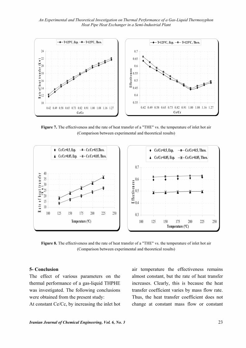
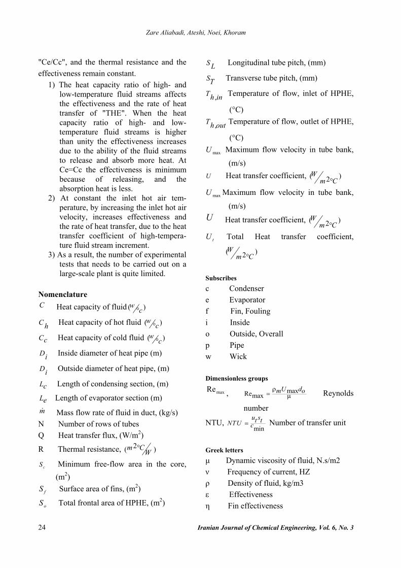
Figure 6. The effectiveness and the rate of heat transfer of a "THE" vs. the temperature of inlet hot air 4.5- Comparison between experimental results and theoretical model In this section, comparison between experimental and theoretical results of effectiveness and transferred heat of a gas to liquid THPHE are carried out. This has been done for inlet hot air in 125-225°C range, Because of the similarity of results only the
comparison of inlet hot air at 125°C is presented here (Tables 2, 3, 4 and Figs. 7, 8). A good agreement between the experimental results of the effectiveness and the rate of heat transfer with the theoretical model has been achieved.

Zare Aliabadi, Ateshi, Noei, Khoram
22 Iranian Journal of Chemical Engineering, Vol. 6, No. 3
Table 2. Experimental and theoretical results of inlet hot air for Thi=125°C
Qtheo..(kw) εtheo. Qexp.(kw) exp.ε Th,o(exp.) (°C)
Tho(theo.) (°C) Ce/Cc Vh
(m/s) hm
(kg/s)
12.292 0.663 11.795 0.63658 63.5 0.421 0.800 0.175
14.913 0.588 14.495 0.57165 72.25 0.577 1.096 0.239
16.984 0.53 16.477 0.51471 75.25 0.73 1.386 0.302
20.039 0.45 19.644 0.44178 77.75 1.00 1.898 0.413
21.361 0.48 20.929 0.47 82 79.5 1.165 2.209 0.481
22.144 0.496 21.682 0.48684 82.5 1.266 2.400 0.523
Table 3. %AAD of experimental and theoretical results for outlet air temperatures (Thi=125°C)
%AAD of Th,o Th,o(exp.) (°C)
Tho(theo.) (°C)
hm (kg/s)
8.66 58 63.5 0.175
10 65 72.25 0.245
5.64 71 75.25 0.319
0.3 78 77.75 0.395
3.1 82 79.5 0.473
3.03 84 82.5 0.543
Table 4. %AAD of experimental and theoretical results for the rate of heat transfer and the effectiveness of THPHE (Thi=125°C)
%AAD of ε %AAD of Q Qtheo..(kw) εtheo. Qexp.(kw) exp.ε
4.24 4.04 12.292 0.663 11.795 0.636
2.9 2.8 14.913 0.588 14.495 0.571
3 3 16.984 0.53 16.477 0.514
2 2 20.039 0.45 19.644 0.441
2.1 2 21.361 0.48 20.929 0.47
2 2.1 22.144 0.496 21.682 0.486
An Experimental and Theoretical Investigation on Thermal Performance of a Gas-Liquid Thermosyphon Heat Pipe Heat Exchanger in a Semi-Industrial Plant
Iranian Journal of Chemical Engineering, Vol. 6, No. 3 23
10
12
14
16
18
20
22
24
0.42 0.49 0.58 0.65 0.73 0.82 0.91 1.00 1.08 1.16 1.27Ce/Cc
Rat
e of
hea
t tra
nsfe
r (K
w)
T=125°C, Exp. T=125°C, Theo.
0.3
0.4
0.5
0.6
0.7
100 125 150 175 200 225 250Temperature (°C)
Eff
ectiv
enes
s
Ce/Cc=0.5, Exp, Ce/Cc=0.5, Theo.
Ce/Cc=0.85, Exp. Ce/Cc=0.85, Theo.
10152025303540
100 125 150 175 200 225 250
Temperature (°C)
Rat
e of
hea
t tra
nsfe
r (K
w)
Ce /Cc=0.5, Exp. Ce/Cc=0.5,Theo.Ce/Cc=0.85, Exp. Ce/Cc=0.85, Theo.
0.35
0.4
0.45
0.5
0.55
0.6
0.65
0.7
0.42 0.49 0.58 0.65 0.73 0.82 0.91 1.00 1.08 1.16 1.27Ce/Cc
Effe
ctiv
enes
s
T=125°C, Exp. T=125°C, Theo.
Figure 7. The effectiveness and the rate of heat transfer of a "THE" vs. the temperature of inlet hot air
(Comparison between experimental and theoretical results)
Figure 8. The effectiveness and the rate of heat transfer of a "THE" vs. the temperature of inlet hot air (Comparison between experimental and theoretical results)
5- Conclusion The effect of various parameters on the thermal performance of a gas-liquid THPHE was investigated. The following conclusions were obtained from the present study: At constant Ce/Cc, by increasing the inlet hot
air temperature the effectiveness remains almost constant, but the rate of heat transfer increases. Clearly, this is because the heat transfer coefficient varies by mass flow rate. Thus, the heat transfer coefficient does not change at constant mass flow or constant
Zare Aliabadi, Ateshi, Noei, Khoram
24 Iranian Journal of Chemical Engineering, Vol. 6, No. 3
"Ce/Cc", and the thermal resistance and the effectiveness remain constant.
1) The heat capacity ratio of high- and low-temperature fluid streams affects the effectiveness and the rate of heat transfer of "THE". When the heat capacity ratio of high- and low-temperature fluid streams is higher than unity the effectiveness increases due to the ability of the fluid streams to release and absorb more heat. At Ce=Cc the effectiveness is minimum because of releasing, and the absorption heat is less.
2) At constant the inlet hot air tem-perature, by increasing the inlet hot air velocity, increases effectiveness and the rate of heat transfer, due to the heat transfer coefficient of high-tempera-ture fluid stream increment.
3) As a result, the number of experimental tests that needs to be carried out on a large-scale plant is quite limited.
Nomenclature C Heat capacity of fluid ( )°
wc
C h Heat capacity of hot fluid ( )°w
c
Cc Heat capacity of cold fluid ( )°w
c
Di Inside diameter of heat pipe (m)
Di Outside diameter of heat pipe, (m)
Lc Length of condensing section, (m)
Le Length of evaporator section (m) m Mass flow rate of fluid in duct, (kg/s) N Number of rows of tubes Q Heat transfer flux, (W/m2)
R Thermal resistance, 2( )m CW
°
cS Minimum free-flow area in the core, (m2)
fS Surface area of fins, (m2)
oS Total frontal area of HPHE, (m2)
S L Longitudinal tube pitch, (mm)
ST Transverse tube pitch, (mm)
,Th in Temperature of flow, inlet of HPHE,
(°C)
,Th out Temperature of flow, outlet of HPHE,
(°C)
maxU Maximum flow velocity in tube bank,
(m/s) U Heat transfer coefficient, ( )2
Wm C°
maxU Maximum flow velocity in tube bank,
(m/s) U Heat transfer coefficient, ( )2
Wm C°
tU Total Heat transfer coefficient,
( )2W
m C°
Subscribes c Condenser e Evaporator f Fin, Fouling i Inside o Outside, Overall p Pipe w Wick Dimensionless groups
maxRe , maxRemaxU dm oρ
= μ Reynolds
number
NTU, min
u st tNTU c= Number of transfer unit
Greek letters μ Dynamic viscosity of fluid, N.s/m2 ν Frequency of current, HZ ρ Density of fluid, kg/m3 ε Effectiveness η Fin effectiveness

An Experimental and Theoretical Investigation on Thermal Performance of a Gas-Liquid Thermosyphon Heat Pipe Heat Exchanger in a Semi-Industrial Plant
Iranian Journal of Chemical Engineering, Vol. 6, No. 3 25
References 1. Vasiliev, L. L., “Heat pipes in modern heat
exchangers”, Applied Thermal Engineering, 25, 1 (2005).
2. Azad, E., and Geoola, F., “A design procedure for gravity-assisted heat pipe heat exchanger”, Heat Recovery Sys. Elsevier Science, 101 (1984).
3. Zhonglliang, L., Zengyi, W., and Chongfang, M., “Experimental study on heat transfer characteristics of heat pipe heat exchanger with latent heat storage. Part І: Charging only and discharging only modes”, Energy Conversion and Management, (2005).
4. Zhonglliang, L., Zengyi, W., and Chongfang, M., “Experimental study on heat transfer Characteristics of heat pipe heat exchanger with latent heat storage. Part ІІ: Simultaneous charging and discharging modes”, Energy Conversion and Management, (2005).
5. Shah, R.K., and Giovannelli, A.D., Heat pipe heat exchanger design theory, Hemisphere, Washington D.C., (1987).
6. Tan, J. O., Liu, C. Y., and Wang, Y. W., “Heat pipe heat exchanger optimization, Heat Recovery System”, 11(4), 313 (1991).
7. Wadowski, T., Akbarzadeh, A., and Johnson, P., “Characteristics of a gravity-assisted heat pipe – based heat exchanger”, Heat Recovery System, 11(1), 69 (1991).
8. Yang, F., Yuan, X. and Lin, G., “Waste heat recovery using heat pipe heat exchanger for heating automobile using exhaust gas” , Applied Thermal Engineering, Elsevier Science, 23, 367 (2003).
9. Noie, S. H., and Majideian, G. R., “Waste heat recovery using heat pipe heat exchanger (HPHE) for surgery rooms in hospitals”, Applied Thermal Engineering, Elsevier Science, 20, 1271 (2000).
10. Noie, S.H., “Investigation of thermal performance of air-to-air thermosyphon heat exchanger using ε-NTU method”, Applied Thermal Engineering, 26, 1073 (2005).
11. Lin, S., Broadbent, J., and McGlan, R., “Numerical study of heat pipe application in heat recovery systems”, Applied Thermal Engineering, 25, 127 (2005).
12. Faghri, A., Heat pipe science and technology, Taylor & Francis, USA, (1995).