an energy-based electroelastic beam model for mems
TRANSCRIPT

An energy-based electroelastic beam model
for MEMS applications
N.E. Ligterink, M. Patrascu, P.C. Breedveld, and S. Stramigioli
Control Engineering, University Twente,Postbus 217, 7500AE Enschede, The Netherlands
Abstract
Competent modeling of an electroelastic beam configuration is of major importancefor MEMS. The MEMS motor, based on such a deformable capacitor, is driven bya voltage source. A coherent model, of limited complexity and expressed in designparameters, is derived for a step motor. The two physical regimes; the stick andnon-stick, are matched, such that a smooth, single energy profile arises. The pull-in voltage, the hysteris loop, jump-back voltage, the step size, and the dissipatedenergies are determined as function of these design parameters. The results arecompared to measurements with the µWalker.
Key words: electroelastic beam, stick, hysteresis, design parameter dependence,energy balance, pull-in voltagePACS: 85.85.+j, 46.70.De, 46.15.Cc, 47.20.Ky
1 Introduction
A well-known effect when modeling and designing MEMS (Micro Electrome-chanical Systems) is that the electrostatic forces scale favorably with decreas-ing size [1]. At the micrometer scale, an applied voltage in a range up to 100Vyields electrostatical forces comparable to the mechanical stiffness of the microstructure. This feature lies at the heart of an effective actuator, in our casean elastic beam with capacitance. The working principle of the elastic beamrelies on a balance between electrostatic and mechanical forces. Step motorsbased on this principle, like the µWalker [2], are being developed for mass
Email addresses: [email protected] (N.E. Ligterink),[email protected] (M. Patrascu), [email protected] (P.C.Breedveld), [email protected] (S. Stramigioli).
Preprint submitted to Elsevier Science 10 March 2005
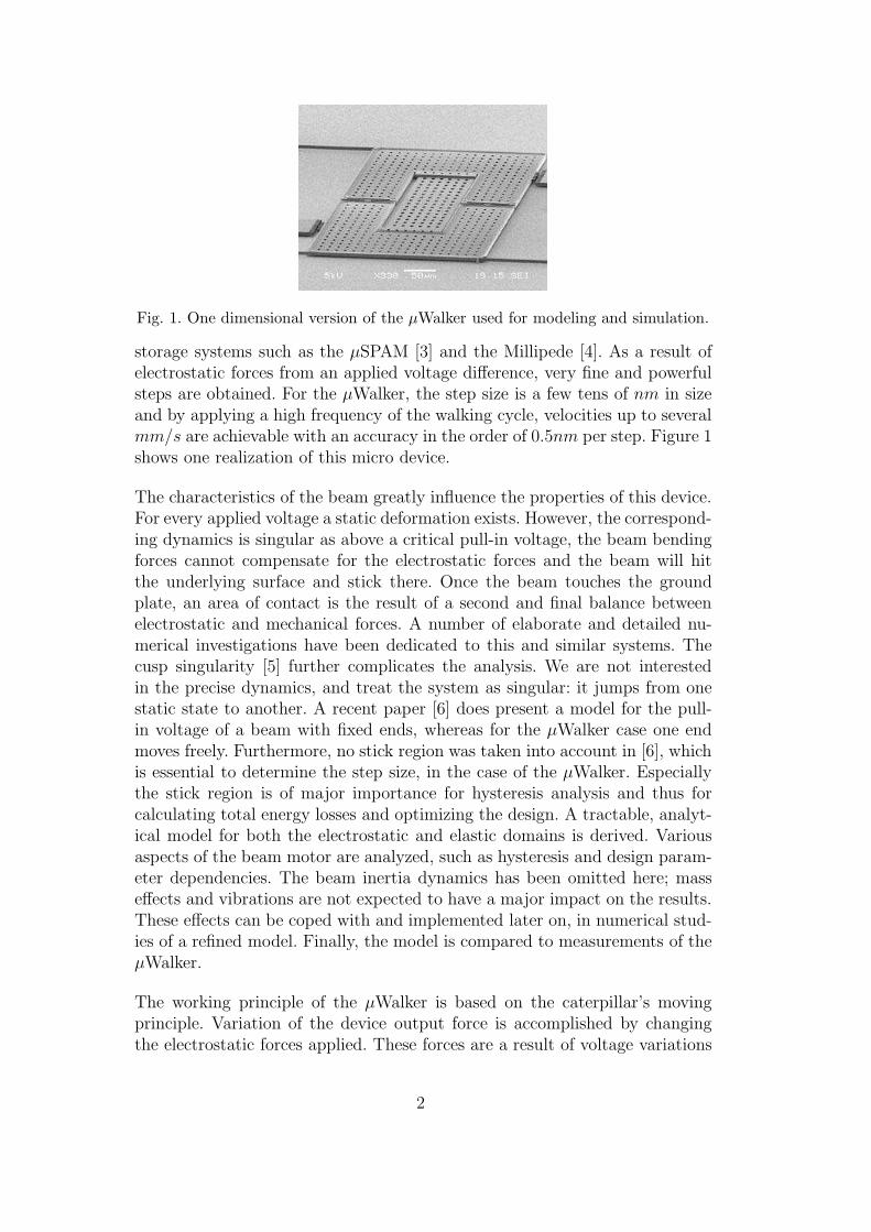
Fig. 1. One dimensional version of the µWalker used for modeling and simulation.
storage systems such as the µSPAM [3] and the Millipede [4]. As a result ofelectrostatic forces from an applied voltage difference, very fine and powerfulsteps are obtained. For the µWalker, the step size is a few tens of nm in sizeand by applying a high frequency of the walking cycle, velocities up to severalmm/s are achievable with an accuracy in the order of 0.5nm per step. Figure 1shows one realization of this micro device.
The characteristics of the beam greatly influence the properties of this device.For every applied voltage a static deformation exists. However, the correspond-ing dynamics is singular as above a critical pull-in voltage, the beam bendingforces cannot compensate for the electrostatic forces and the beam will hitthe underlying surface and stick there. Once the beam touches the groundplate, an area of contact is the result of a second and final balance betweenelectrostatic and mechanical forces. A number of elaborate and detailed nu-merical investigations have been dedicated to this and similar systems. Thecusp singularity [5] further complicates the analysis. We are not interestedin the precise dynamics, and treat the system as singular: it jumps from onestatic state to another. A recent paper [6] does present a model for the pull-in voltage of a beam with fixed ends, whereas for the µWalker case one endmoves freely. Furthermore, no stick region was taken into account in [6], whichis essential to determine the step size, in the case of the µWalker. Especiallythe stick region is of major importance for hysteresis analysis and thus forcalculating total energy losses and optimizing the design. A tractable, analyt-ical model for both the electrostatic and elastic domains is derived. Variousaspects of the beam motor are analyzed, such as hysteresis and design param-eter dependencies. The beam inertia dynamics has been omitted here; masseffects and vibrations are not expected to have a major impact on the results.These effects can be coped with and implemented later on, in numerical stud-ies of a refined model. Finally, the model is compared to measurements of theµWalker.
The working principle of the µWalker is based on the caterpillar’s movingprinciple. Variation of the device output force is accomplished by changingthe electrostatic forces applied. These forces are a result of voltage variations
2
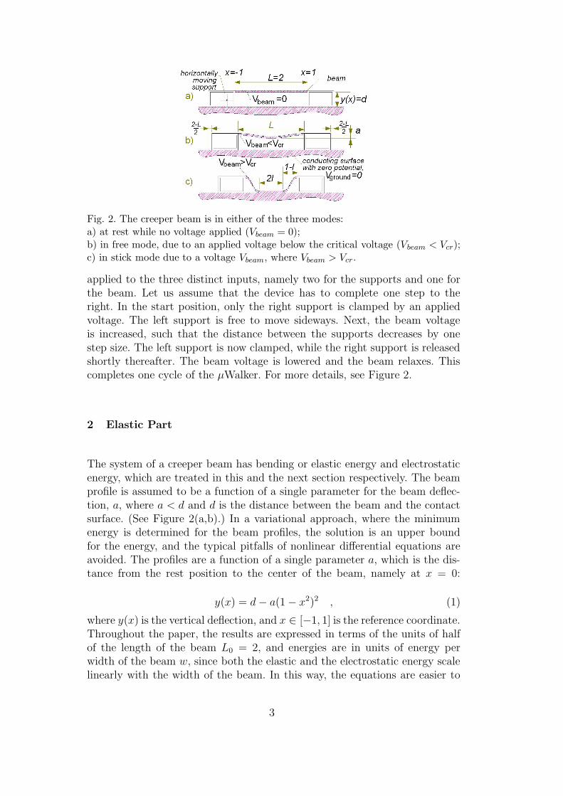
Fig. 2. The creeper beam is in either of the three modes:a) at rest while no voltage applied (Vbeam = 0);b) in free mode, due to an applied voltage below the critical voltage (Vbeam < Vcr);c) in stick mode due to a voltage Vbeam, where Vbeam > Vcr.
applied to the three distinct inputs, namely two for the supports and one forthe beam. Let us assume that the device has to complete one step to theright. In the start position, only the right support is clamped by an appliedvoltage. The left support is free to move sideways. Next, the beam voltageis increased, such that the distance between the supports decreases by onestep size. The left support is now clamped, while the right support is releasedshortly thereafter. The beam voltage is lowered and the beam relaxes. Thiscompletes one cycle of the µWalker. For more details, see Figure 2.
2 Elastic Part
The system of a creeper beam has bending or elastic energy and electrostaticenergy, which are treated in this and the next section respectively. The beamprofile is assumed to be a function of a single parameter for the beam deflec-tion, a, where a < d and d is the distance between the beam and the contactsurface. (See Figure 2(a,b).) In a variational approach, where the minimumenergy is determined for the beam profiles, the solution is an upper boundfor the energy, and the typical pitfalls of nonlinear differential equations areavoided. The profiles are a function of a single parameter a, which is the dis-tance from the rest position to the center of the beam, namely at x = 0:
y(x) = d− a(1− x2)2 , (1)
where y(x) is the vertical deflection, and x ∈ [−1, 1] is the reference coordinate.Throughout the paper, the results are expressed in terms of the units of halfof the length of the beam L0 = 2, and energies are in units of energy perwidth of the beam w, since both the elastic and the electrostatic energy scalelinearly with the width of the beam. In this way, the equations are easier to
3

follow. Only at the end, the value of L0 is set equal to the real beam lengthof the µWalker.
From numerical studies [7], the profile chosen has an appropriate shape, giventhe clamped boundary conditions. Even if small deviations of the beam shapeoccur, their influence on the energy is only of second order and negligible. Theenergy functional has an elastic and an electrostatic part which are determinedbelow.
In simple beam models like the Euler-Bernoulli beam, only the vertical dis-placement y as a function of the horizontal rest, or reference coordinate x isdetermined. In our case, the horizontal displacement is also important for thewalking motion. The length of the beam is taken to be fixed in the absence ofstress through friction. Therefore, the horizontal position X(x) as function ofthe reference coordinate x should satisfy:
1 = (∂xX(x))2 + (∂xy(x))2 ,
which is satisfied to second order in a by:
∂xX(x) = 1− 1
2(∂xy(x))2 = 1− 8a2(1− x2)2x2 ,
where is assumed that |1− ∂xX(x)| � |∂xy(x)|, since a � 1. The horizontaldistance L between the ends at x = −1 and x = 1 is therefore given by:
L =∫ 1
−1∂xX(x)dx = 2− 128
105a2 . (2)
The bending energy Eb of a fixed length beam is a function of the beamcurvature k[8]:
Eb =∫ 1
−1
κ
2k2(x)dx ,
where the constant κ is given by:
κ = EI ,
and for the curvature k holds:
k(x) = ∂xy(x)∂2xX(x)− ∂xX(x)∂2
xy(x) ,
since the beam length is a unit function of x. For the given profile, this reducesto the Euler-Bernoulli result [9]:
k(x) ≈ −∂2xy(x) = −4a(1− 3x2) ,
Eb = κ64
5a2 =
64
5EIa2 , (3)
4

where E is Young’s elasticity modulus, and I the moment of inertia in thedirection of bending, which equals b3/12, where b is the beam thickness. Notethat both the elastic and the electrostatic energy are proportional to the widthof the beam. Therefore, the energy is expressed per unit width.
Of course it is possible to have a more elaborate model of the energy, includinghigher-order terms in a. However, for qualitative results they are of little con-sequence, as we will see. Furthermore, given the simple one-parameter ansatzfor the beam profile, the approximations are within the same order.
3 Electrostatic Part
The beam itself is a conductor, therefore inside the beam the electric field iszero. For a given potential, the electric field E‖(x) between the beam and thefloor is given by the voltage V divided by the distance between beam and floory(x):
E‖(x) =V
y(x).
Since d� L, we assume the perpendicular component of the electric field E⊥,pointing in the horizontal direction, to first approximation to be negligible.The electric field is the consequence of the surface charge density ρ(x) whichis consequently proportional to the strength of the field [10]:
ρ(x) = ε0E‖(x) .
Later, it will be shown that the parallel field approximation holds for allphysical configurations. For small values of a, if d� L, the curvature is smalland the beam shape is almost flat. Since large values of a, (a > d/2) are notstable, those configurations will not occur and when the beam sticks to theground plate, the electrostatic energy is dominated by the sticking part. Inthe case of stick, the gap field, parallel or not, can be neglected. In Figure 3the equipotential lines of a very short beam at a very large deflection areshown. Even in that extreme case the field is almost parallel. In practice, inthis case the beam will stick to the ground floor. In the operational practicethe supports may have different voltages compared to the beam, however, thiswill have neglible effects for the typical flat configuration, where d� L.
The total electrostatic energy Ee can be expressed as:
5
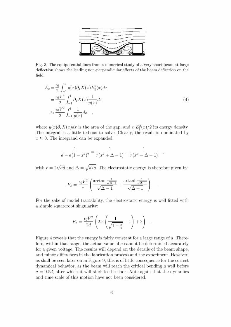
Fig. 3. The equipotential lines from a numerical study of a very short beam at largedeflection shows the leading non-perpendicular effects of the beam deflection on thefield.
Ee =ε02
∫ 1
−1y(x)∂xX(x)E2
‖(x)dx
=ε0V
2
2
∫ 1
−1∂xX(x)
1
y(x)dx (4)
≈ ε0V2
2
∫ 1
−1
1
y(x)dx ,
where y(x)∂xX(x)dx is the area of the gap, and ε0E2‖(x)/2 its energy density.
The integral is a little tedious to solve. Clearly, the result is dominated byx ≈ 0. The integrand can be expanded:
1
d− a(1− x2)2=
1
r(x2 + ∆− 1)− 1
r(x2 −∆− 1),
with r = 2√ad and ∆ =
√d/a. The electrostatic energy is therefore given by:
Ee =ε0V
2
r
arctan 1√∆−1√
∆− 1+
artanh 1√∆+1√
∆ + 1
.
For the sake of model tractability, the electrostatic energy is well fitted witha simple squareroot singularity:
Ee =ε0V
2
2d
2.2
1√
1− ad
− 1
+ 2
.
Figure 4 reveals that the energy is fairly constant for a large range of a. There-fore, within that range, the actual value of a cannot be determined accuratelyfor a given voltage. The results will depend on the details of the beam shape,and minor differences in the fabrication process and the experiment. However,as shall be seen later on in Figure 9, this is of little consequence for the correctdynamical behavior, as the beam will reach the critical bending a well beforea = 0.5d, after which it will stick to the floor. Note again that the dynamicsand time scale of this motion have not been considered.
6
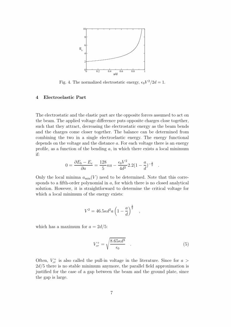
Fig. 4. The normalized electrostatic energy, ε0V2/2d = 1.
4 Electroelastic Part
The electrostatic and the elastic part are the opposite forces assumed to act onthe beam. The applied voltage difference puts opposite charges close together,such that they attract, decreasing the electrostatic energy as the beam bendsand the charges come closer together. The balance can be determined fromcombining the two in a single electroelastic energy. The energy functionaldepends on the voltage and the distance a. For each voltage there is an energyprofile, as a function of the bending a, in which there exists a local minimumif:
0 =∂Eb − Ee
∂a=
128
5κa− ε0V
2
4d22.2(1− a
d)−
32 .
Only the local minima amin(V ) need to be determined. Note that this corre-sponds to a fifth-order polynomial in a, for which there is no closed analyticalsolution. However, it is straightforward to determine the critical voltage forwhich a local minimum of the energy exists:
V 2 = 46.5κd2a(
1− a
d
) 32
,
which has a maximum for a = 2d/5:
V +cr =
√8.65κd3
ε0. (5)
Often, V +cr is also called the pull-in voltage in the literature. Since for a >
2d/5 there is no stable minimum anymore, the parallel field approximation isjustified for the case of a gap between the beam and the ground plate, sincethe gap is large.
7

Fig. 5. The surface now also consists of an insulation layer of thickness dlayer andwith permittivity εr.
5 Stick
When the beam hits the floor, it will stick there. (See Fig. 2(c).) In practice,a small insulating layer exists with electric permittivity εr, which preventscharge displacement between the beam and the surface in case there is contact.(See Figure 5.) This situation is entirely different from the free beam of theprevious section, and determined mainly by the properties of the stick. First,the energy associated with stick is determined. Second, the configurations areparametrized by the size of the contact length l.
The distance h between the beam and the conduction floor is an effectivethickness, which combines the electric permittivities of the airgap and theinsulating layer:
h = d+dlayer
εr= d(1 + δ) ,
where δ � 1. The corresponding energy is referred to as the stick energy Es
and can be obtained from the energy density Ds:
Ds =ε0V
2
2dδ,
Es = 2lDs . (6)
As can be seen in Figure 2(c), the configuration is thus extended beyond a = dby including a stick domain of length 2l, and two bending domains, each ofthe length 1 − l. The bending energy can be determined from the free case.The two ends can be glued together to yield the a = d case, with scaledx→ x/(1− l) coordinates. The bending energy scales appropriately:
Estickb (l) =
1
(1− l)3Eb(a = d) =
64κd2
5(1− l)3.
The electrostatic energy of the bending part scales with the area:
Esticke (l) = (1− l)Ee(a = d)
= (1− l)ε0V2
d
(1.1√δ− 0.1
). (7)
8

Fig. 6. A sketch of the configuration variable ξ. The vertical path is the distancebetween the beam and the floor, at ξ = 1 the beam touches the floor, the horizontalpath is the edge of the contact area.
The total energy of the stick situation is given by:
Estick = Estickb (l)− Estick
e (l)− Es . (8)
The minimum energy is given through the variation with respect to l, wherethe Estick
e (l) term is assumed to be of small importance since δ �√δ. The
analysis presented in [11] confirms this. The length of the stick area, for theminimum energy:
lmin = 1− 4
√192κd3δ
5ε0V 2.
If lmin is real negative, then the beam will stick at the boundary point, lmin = 0.This situation occurs, since the first derivative of the energy kinks downwardsat the cross-over between stick and free mode, creating a cross-over minimum,since in each domain, stick and non-stick, the boundary value is a local mini-mum.
The distance between the beam ends changes further as the stick area in-creases. In principle it would scale with (1− l)−1, however, for values of l → 1,the approximation fails. The corrected length incorporates this effect:
L = 2− 128
105
d2
1− (1− 64105d)l
,
yielding a minimal distance of L0 − 2d for l = 1, where L0 = 2 is the beam
9
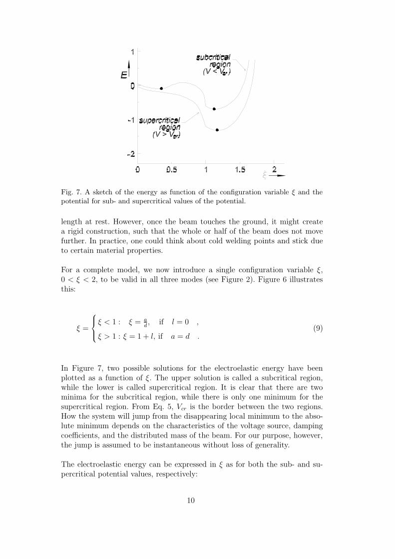
Fig. 7. A sketch of the energy as function of the configuration variable ξ and thepotential for sub- and supercritical values of the potential.
length at rest. However, once the beam touches the ground, it might createa rigid construction, such that the whole or half of the beam does not movefurther. In practice, one could think about cold welding points and stick dueto certain material properties.
For a complete model, we now introduce a single configuration variable ξ,0 < ξ < 2, to be valid in all three modes (see Figure 2). Figure 6 illustratesthis:
ξ =
ξ < 1 : ξ = a
d, if l = 0 ,
ξ > 1 : ξ = 1 + l, if a = d .(9)
In Figure 7, two possible solutions for the electroelastic energy have beenplotted as a function of ξ. The upper solution is called a subcritical region,while the lower is called supercritical region. It is clear that there are twominima for the subcritical region, while there is only one minimum for thesupercritical region. From Eq. 5, Vcr is the border between the two regions.How the system will jump from the disappearing local minimum to the abso-lute minimum depends on the characteristics of the voltage source, dampingcoefficients, and the distributed mass of the beam. For our purpose, however,the jump is assumed to be instantaneous without loss of generality.
The electroelastic energy can be expressed in ξ as for both the sub- and su-percritical potential values, respectively:
10

E<(ξ, V ) =1
2Kξ2 − 1
2CV 2 1√
1 + δ − ξ , (10)
E>(ξ, V ) =1
2
K
(2− ξ)3− 1
2CV 2 1
δ(ξ − 1 +
√δ) , (11)
where C = 2ε0√
1+δh
is the electric capacity and K = 325EId2 is the normal-
ized mechanical bending stiffness, see Eq. 3. The small constant terms weredisregarded.
In the case of absolute units, there holds:
C =wL0ε0
d√
1 + δ, (12)
K =32EId2
5L30
= w64
15L30
Eb3d2 , (13)
where L0 is the length of the beam, and b the thickness of the beam. Themoment of inertia is given as:
I =∫ 1
2w
12wdy∫ 1
2b
12bz2dz =
wb3
12.
The absolute scaling of the model shows that C scales linearly with size andK with the cube of the size, such that the critical voltage scales linearly withsize (See Eq. 5.) Hence, a smaller system requires an equally smaller workingvoltage.
6 Point Stick and Hysteresis
Point stick is a local minimum of the energy function at ξ = 1, if the left-derivative of the energy profile is negative and the right derivative is positive.In this case, the beam will touch the ground plate at a single point. Thissituation occurs for
4Kδ32
C< V 2 <
3Kδ
C.
Therefore the critical jump-back voltage for the situation from stick-to-free isthe lower bound of the point stick:
V −cr =
√√√√4Kδ32
C.
11
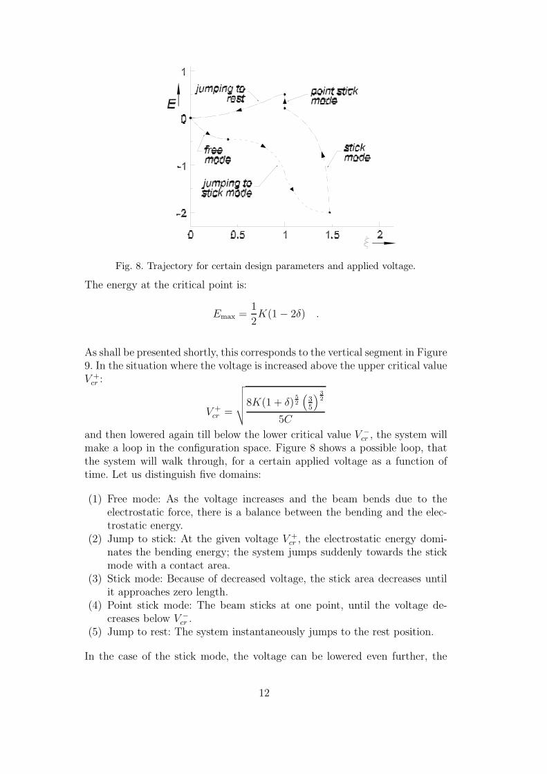
Fig. 8. Trajectory for certain design parameters and applied voltage.
The energy at the critical point is:
Emax =1
2K(1− 2δ) .
As shall be presented shortly, this corresponds to the vertical segment in Figure9. In the situation where the voltage is increased above the upper critical valueV +cr :
V +cr =
√√√√√8K(1 + δ)52
(35
) 32
5C
and then lowered again till below the lower critical value V −cr , the system willmake a loop in the configuration space. Figure 8 shows a possible loop, thatthe system will walk through, for a certain applied voltage as a function oftime. Let us distinguish five domains:
(1) Free mode: As the voltage increases and the beam bends due to theelectrostatic force, there is a balance between the bending and the elec-trostatic energy.
(2) Jump to stick: At the given voltage V +cr , the electrostatic energy domi-
nates the bending energy; the system jumps suddenly towards the stickmode with a contact area.
(3) Stick mode: Because of decreased voltage, the stick area decreases untilit approaches zero length.
(4) Point stick mode: The beam sticks at one point, until the voltage de-creases below V −cr .
(5) Jump to rest: The system instantaneously jumps to the rest position.
In the case of the stick mode, the voltage can be lowered even further, the
12

Fig. 9. The trajectories of the system indicated through the two line segments, theleft one for increasing voltage (going into stick mode), the right one for decreasingvoltage (releasing from stick mode).
stick domain indicated by ξ > 1 will then decrease. The value of ξ for whichthe energy acquires a minimum for a given voltage is given by:
ξ = 2− 4
√3Kδ
CV 2.
The corresponding energy follows from the virial theorem:
Emin = −(314 − 3−
34 )K
14C
34V
32
2δ34
+1
2CV 2(1−
√δ) .
As an aggregation, Figure 9 shows one of several possible system trajectories,depending on physical parameters. The left segment represents the beam forincreasing voltage starting at V = 0, where the beam is stuck in the bendminimum. The right part is for decreasing voltage, when the system is stuck inthe stick minimum. The vertical segment indicates the point contact sticking.The zoom-in shows that there is indeed a flat minimum, which disappearsbelow a certain energy profile, and thus the local minimum also disappears.Formally, at this point (ξcr) holds:
∂E (ξ)
∂ξ
∣∣∣∣∣∣ξ↓ξcr
=∂2E (ξ)
∂ξ2
∣∣∣∣∣∣ξ↓ξcr
= 0 .
The energy loss in the system during a cycle is associated with the two jumps,when the voltage crosses the two critical values V +
cr and V −cr . The down jump
13

Fig. 10. The µWalker dimensions assumed.
corresponds to an energy jump (ξ = 25(1 + δ)→ ξ = 2− 4
√3Kδ/CV +
cr2):
∆E↓ = Emin(V +cr )− 2K(1 + δ)2
25+
CV +cr
2
2√
35(1 + δ)
,
while the up jump corresponds to an energy jump (ξ = 1→ ξ = 0):
∆E↑ = Emax =1
2K(1− 2δ) .
Thus, the total energy needed for one cycle equals:
Etot = ∆E↓ + ∆E↑ .
7 The µWalker - a case
As a test case, a design similar to the µWalker is presented in [2]. The bulkmaterial is Silicon (Si), whereas the insulation layer consists of Silicon nitride(SIRN). The Silicon nitride has a dielectric constant in the range of 5 to 8, anda dielectric strength of about 1.0− 2.0 108V/m. In the case of voltages below100V , a layer of 1.0µm is sufficient for reaching the stick phase. However, in thecase of the µWalker, the bottom surface is specially prepared for enhancingsliding properties. The thickness of the dielectric layer is 0.210µm, but theeffective thickness is much larger than the corresponding δ = 0.03, due tothe prepared contact area of the beam with small pins of about the sameheight. The small pins create an airgap when the beam hits the ground plate.The original design, without pins, stuck to the ground plate, even after thevoltage was decreased. This was the result of large stick energy, due to thesmall value of δ. Although, we have not been able to determine δ accuratelyfrom the design, the size of the pins suggests an effective Silicon-nitride-airlayer of around δ = 0.2, which is mainly due to the large airgap. This valuecan experimentally be obtained from the step size.
The length L0 of the beam is 180µm and the distance d to the floor is 1.85µm.Figure 10 shows the dimensioning assumed. The width of the beam is 94µm,which justifies the parallel field approximation in the third direction. The beamitself has a thickness of 1.2µm, which corresponds to a moment of inertia of
14

Fig. 11. The squares are the measured step sizes. The solid line is the step sizefrom the model. The dashed line is the step size for the adjusted beam thickness of1.35µm.
I = 1.35 10−23m3. For an Young’s modulus of E ≈ 150 109Pa, Equations 12and 13 give:
K = 6.1 10−11Nm−1 , (14)
C = 7.4 10−14F . (15)
According to the model proposed, the upper critical voltage V +cr ≈ 31V , while
the lower critical voltage V −cr ≈ 17V . The maximal displacement in a singlecycle is about 50 nm, if it is assumed that half of the beam is fixed once ittouches the ground plate, while the other half still pulls inward. In Figure 11some measured step sizes of the µWalker are plotted together with the resultsof the model presented, including the parameters from above. The resultsdepend strongly on the thickness of the beam. A slight adjustment of thebeam thickness from 1.2µm to 1.35µm would diminish the small discrepancyin the pull-in voltage between the model and the measurements, as can be seenin the figure. The results depend only weakly on the effective layer thicknessδ. A smaller delta would increase the step size, but would leave the pull-involtage the same.
8 Conclusions
For the sake of simplicity, dynamical effects were ignored throughout the pa-per. In principle, the system will stay in the local energy minimum if thechanges are infinitely slow. If the changes occur faster, the system will buildup inertia, which could lower the energy barriers and the pull-in voltage. Fur-thermore, if the kinetic energy is not enough to jump the barrier, the systemwill start to oscillate around the minimum. In fact, the point stick situation
15

will quickly disappear due to dynamical effects. From Figure 9 it is clear thatfor values of ξ slightly smaller than 1, the system will slide back to ξ ≈ 0, ifthe voltage is relatively low. This can also be observed in practice.
The model presented identifies the relevant parameters of the creeper-beamsystem: the stiffness K, the capacity C, and the insulator thickness δ. Espe-cially the latter is seldom mentioned as an important design parameter forthe stick regime. The precise numerical coefficients play a secondary role infinding the analytical dependence of several quantities on the design parame-ters. Furthermore, the model gives a clear handle on the different dynamicalregimes, and identifies a third configuration regime, namely the point-contactstick, for a range of applied voltages. In a more elaborate model, where thebending is not simply modeled by a single parameter, this could be furtherinvestigated. However, the scope of this paper is limited to quantify the mainfeatures of the creeper beam model, such that the relevant parameters andtheir effects are identified.
For a model with only one parameter that has been fitted to experiments,namely δ, the results compare very well to the measurements. Moreover, itcan be used to fit the data using the three parameters K, C, and δ, such thatdifferent properties relevant for design, such as step size, deformation, andforce can be compared. As has been remarked in Section 5, smaller dimensionsof the beam imply smaller working voltages.
It should be mentioned that friction between the supports and the groundplate may cause stresses in the beam which reduce the step size. In this casethe beam will act as a spring rather than fixed-length, bending beam. Thedynamical effects – for example as a result of beam inertia – will limit the op-eration speed since the mechanical effects do not occur instantaneously withthe change of the voltage. All these effects are under investigation, both innumerical as well as in experimental studies. However, the simple model pre-sented here has been the guiding principle, as it covers the dominant behaviorof the electroelastic beam.
Future work will include 20-SIM modeling of the µWalker as a complete systemincluding stick-slip, friction and other effects that play a great role in the everinteresting world of micro and nano devices.
9 Acknowledgments
The authors would like to thank E. Sarajlic and the µSPAM group for the ex-perimental data. This work was sponsored by STW through projects TWI.6012and TES.5178.
16

References
[1] M. J. Madou, Fundamentals of Microfabrication – The Science ofMiniaturization, 2nd Edition, CRC Press, (London 2002), ISBN 0-8493-0826-7
[2] T. Lammerink, M. Elwenspoek, L. Sander, J. Wissink and N. Tas, Modeling,Design and testing of the electrostatic shuffle motor, Sensors and Actuators A70 (1998) pp. 171-178.
[3] M. Bolks, F. Hanssen, L. Abelmann, P. Havinga, P. Hartel, P. Jansen, C.Lodder, G. Smit, Micro Scanning Probe Array Memory (µSPAM), Proceedingssecond Progress workshop, Veldhoven, the Netherlands, pp. 17-26, ISBN 90-73461-26-X, October 2001.
[4] P. Vettiger, G. Cross, M. Despont, U. Drechsler, U. Uurig, B. Gotsmann, W.Haberle, M. A. Lantz, H. E. Rothuizen, R. Stutz, and G. K. Binning, The“Millipede” – Nanotechnology Entering Data Storage, IEEE Transactions onNanotechnology 1, June 2002.
[5] V. I. Arnold, Catastrophe theory, Springer (Berlin, 1984). T. Poston andI. Stewart, Catastrophe theory and its applications, Pitman (San Fransisco,1978).
[6] H. Rong, Q. A. Huang, M. Nie, W. Li, An analytical model for pull-in voltageof clamed-clamped multilayer beams, Sensors and Actuators A 112 (in press).
[7] Y. Zhou, X. Yang, Numerical analysis on snapping induced byelectromechanical interaction of shuffling actuator with nonlinear plage,Computers and Structures 81 (2003) pp. 255-264.
[8] H. W. Guggenheimer, Differential geometry, McGraw-Hill (New York, 1963).
[9] A. E. H. Love, A treatise on the mathematical theory of elasticity, Dover (NewYork, 1927).
[10] J. D. Jackson, Classical electrodynamics, Wiley (New York, 1962).
[11] Mallon J.R., F. Pourahmadi, K. Petersen, P. Barth, T. Vermeulen, J. Brezek,Low pressure sensors employing bossed diaphragms and precision etch-stopping, Sensors and Actuators A 21-23 (1990) pp. 89-95.
17

• Norbert E. Ligterink received the M.Sc. in Theoretical Physics withhonors (cum laude) in 1992 and the Ph.D. in Theoretical Nuclear Physicsin 1996. Thereafter he worked at UMIST in Manchester, UK, at ECT*,in Trento, Italy, and at the University of Pittsburgh, USA, on the field-theoretical description of nucleonic and sub-nucleonic bound states. Since2003 he is a graduate student again. The topic of his Ph.D. is the modelingand control of distributed parameter systems.• Mihai Patrascu received his M.Sc. in 2002 at the Delft University of
Technology. He now is a Ph.D. student at the University of Twente, theNetherlands. His interests lie in physical modeling and simulation of microelectro-mechanical systems and new data storage concepts.• Peter C. Breedveld is an associate professor with tenure at the University
of Twente, Netherlands, where he received an M.Sc. in 1979 and a Ph.D in1984. He has been a visiting professor at the University of Texas at Austinin 1985 and at the Massachusetts Institute of Technology in 1992-1993. Heis or has been a consultant for several large industrial research labs. Heinitiated the development of the modeling and simulation tool that is nowcommercially available under the name 20-sim. In 1990 he received a FordResearch grant for this work in the area of physical system modeling andthe design of computer aids for this purpose.
He is an associate editor of the ’Journal of the Franklin Institute’, SCS’Simulation’ and ’Mathematical and Computer Modeling of Dynamical Sys-tems’. His scientific interests are: integrated modeling, control and designof physical systems; generalized thermodynamics; simulation, analysis anddesign; numerical methods, applied electromagnetism and many more.• Stefano Stramigioli received the M.Sc. with honors (cum laude) in 1992
and the Ph.D with honors (cum laude) in 1998. Since 1998 he has beenfaculty member first as assistant and then associate professor. He is currentlyan officer and Senior Member of IEEE. He has more than 60 publicationsincluding a book. He is Editor in Chief of the IEEE Magazine of Roboticsand Automation, and has been guest editor for others. He is a member ofthe ESA Topical Team on Dynamics of Prehension in Micro-gravity and itsapplication to Robotics and Prosthetics. He is involved in different projectsrelated to Control, Robotics and MEMS and coordinator of the EuropeanProject named Geoplex (http://www.geoplex.cc). He has been teachingModeling, Control and Robotics for under and post-graduates and receivedteaching nominations and an award.
18
FIGURE CAPTIONS
(1) One dimensional version of the µWalker used for modeling and simula-tion.
(2) The creeper beam is in either of the three modes:a) at rest while no voltage applied;b) in free mode, due to an applied voltage below the critical voltage(V1 < Vcr);c) in stick mode due to a voltage V2, where V2 > Vcr.
(3) The equipotential lines from a numerical study of a very short beam atlarge deflection shows the leading non-perpendicular effects of the beamdeflection on the field.
(4) The normalized electrostatic energy, ε0V2/2d = 1.
(5) The surface now also consists of an insulation layer of thickness dlayer andwith permittivity εr.
(6) A sketch of the configuration variable ξ. The vertical path is the distancebetween the beam and the floor, at ξ = 1 the beam touches the floor, thehorizontal path is the edge of the contact area.
(7) A sketch of the energy as function of the configuration variable ξ and thepotential for sub- and supercritical values of the potential.
(8) Trajectory for certain design parameters and applied voltage.(9) The trajectories of the system indicated through the two line segments,
the left one for increasing voltage (going into stick mode), the right onefor decreasing voltage (releasing from stick mode).
(10) The µWalker dimensions assumed.(11) The squares are the measured step sizes. The solid line is the step size
from the model. The dashed line is the step size for the adjusted beamthickness of 1.35µm.
19