an electrical substation is a part of an electricity …...introduction an electrical substation is...
TRANSCRIPT

INTRODUCTION
An electrical substation is a part of an electricity generation, transmission and distribution system where voltage is transformed from high to low or in reverse using transformers. It also serves as a point of connection between various power system elements such as transmission lines, transformers, generators and loads. To allow for flexibility in connecting the elements, circuit breakers are used as high power switches. Electric power may flow through several substations between generating plant and consumer, and may be changed in voltage in several steps. There are different kinds of substation such as Transmission substation, distribution substation, collector substation, switching substation and some other typesof substation. The general functions of a substation may include:
voltage transformation connection point for transmission lines switchyard for network configuration monitoring point for control center protection of power lines and apparatus Communication with other substations and regional control
center
The first step towards the design of a 400/220/132 KVsubstation is to determine the load that the substation has tocater and develop it accordingly. The substation is responsiblefor catering bulk power to various load centres distributed allaround through 220 KV and 132 KV substations. The substationis fed 1316 MW power from 3 generating stations A,B,C through400 KV single circuit lines working at around 87% loading. Thepower is received on 400 KV busbar (double main and transferbus scheme). 636 MW power is dispatched to a 400 KVsubstation ‘a’ catering an area having diversity factor 1.1through 400 KV double circuit lines working at 70% loading.
The remaining 680 MW is fed to three 315 MVA (=3 x10⁵ MVA units) autotransformers working at an average 80%loading and 0.9 power factor. The 315 MVA transformers stepdown the voltage from 400 KV to 220 KV. 6% of the input power680 MW i.e. around 40 MW power is lost in the transformers.

The rest i.e.640 MW is fed to the 220 KV busbar (double mainand transfer bus scheme). To increase the reliability of thesystem the 220 KV busbar is also fed from 2 other substations.A single circuit line from station E working at 68% loadingsupplies 85 MW while a double circuit line from station Dworking at 70% loading supplies 175 MW power to the busbar.This ensures continuity of supply to certain extent even whenan entire 315 MVA transformer unit fails to operate. Thus totalincoming power on 220 KV bus is (640+175+85 =)900 MW.From the 220 KV bus two 220 KV single circuit lines are drawnat 90% loading to supply power to 220KV substations ‘b’and ‘c’working at a diversity factor of 1.35 to cater 112.5 MW each.Three 220 KV double circuit lines working at 80% loading feedssubstations ‘d’,’e’,’f’ working at a diversity factor of 1.35 tomeet a demand of 200 MW each.
The remaining 288 MW is fed to three 160 MVAautotransformers working at an average 75% loading and 0.8power factor. The 160 MVA transformers step down the voltagefrom 220 KV to 132 KV. 6% of the input power 288 MW i.e.around 17 MW power is lost in the transformers. The resti.e.271 MW is fed to the 132 KV busbar(double main busscheme). To increase the reliability of the system the 132 KVbusbar is also fed from another substation. A 132 KV doublecircuit line working at 54% loading delivers 54 MW power to the132 KV bus. This arrangement similar to the one for 220 KV busand ensures that the substation is not inconvenienced to agreat extent if somehow a 160 MVA transformer goes out. Totalincoming power on 132 KV bus is (271+54 =)325 MW. From the132 KV bus five 220 KV double circuit lines working at 90%loading feeds substations ‘g’,’h’,’i’,’j’,’k’ working at a diversityfactor of 1.45 to meet a demand of 90 MW each.
After dispatching 310 MW power, the remaining 15 MWpower available from 132 KV bus is stepped down using 132/33KV & 33/0.415 KV two winding transformers. This power is usedfor auxiliary purposes like pumping, lighting, ac and ventilation

purposes within the substation to ensure its smoothfunctioning.
To compensate for any reactive power deficit or to balance excess reactive power of lightly loaded lines Static VAR Compensators (SVCs) are used.
SURGE IMPEDENCE :
The characteristic impedance or surge impedance of a
uniform transmission line, usually written Z0, is the ratio of the
amplitudes of voltage and current of a single wave propagating
along the line; that is, a wave travelling in one direction in the
absence of reflections in the other direction. Characteristic
impedance is determined by the geometry and materials of the
transmission line and, for a uniform line, is not dependent on its
length.
The general expression for the characteristic impedance of a
transmission line is:
where
is the resistance per unit length, considering the two conductors to be in series,

is the inductance per unit length, is the conductance of the dielectric per unit length, is the capacitance per unit length, is the imaginary unit, and
is the angular frequency.
For a lossless line, R and G are both zero, so the equation for
characteristic impedance reduces to:
The imaginary term j has also canceled out, making Z0 a real
expression, and so is purely resistive.
SURGE IMPEDENCE LOADING :
In electric power transmission, the characteristic impedance of
a transmission line is expressed in terms of the surge
impedance loading (SIL), or natural loading, being the power
loading at which reactive power is neither produced nor
absorbed:
in which is the line-to-line voltage in
Loaded below its SIL, a line supplies reactive power to the
system, tending to raise system voltages. Above it, the line
absorbs reactive power, tending to depress the voltage.
The Ferranti effect describes the voltage gain towards the
remote end of a very lightly loaded (or open ended)
transmission line. Underground cables normally have a very low
characteristic impedance, resulting in an SIL that is typically in
excess of the thermal limit of the cable. Hence a cable is almost
always a source of reactive power.

Figure below is a graphic illustration of the concept of SIL. This particular line has a SIL of 450 MW. Therefore is the line is loaded to 450 MW (with no Mvar) flow, the Mvar produced by the line will exactly balance the Mvar used by the line.
SUBSTATION LOAD DISTRIBUTION DIAGRAM

SURVEY AREA
LOAD BALANCE SHEET

Incoming power (MW) Outgoing power (MW)
From 3 generating stationsA,B,C
1316To 400 KV substation through400 KV double ckt line
636
From substation D through 220KV double ckt line
175To 220 KV area through 5 220KV substations
612
From substation E through 220KV single ckt line
85To 132 KV area through 5 132KV substations
310
From substation F through 132KV double ckt line
54 To Internal loading 15
As loss in 3 315 MVAtransformers
40
As loss in 3 160 MVAtransformers
17
Total 1630 Total 1630
SELECTION OF SITE:
Selection of site for construction of a Grid Sub Station is the first and important activity. This needs meticulous planning, fore-sight, skillful observation and handling so that the selectedsite is technically, environmentally, economically and socially optimal and is the best suited to the requirements.
The site should be:
(a)As near the load centre as possible.
(b) As far as possible rectangular or square in shape for ease of proper orientation of bus– bars and feeders.
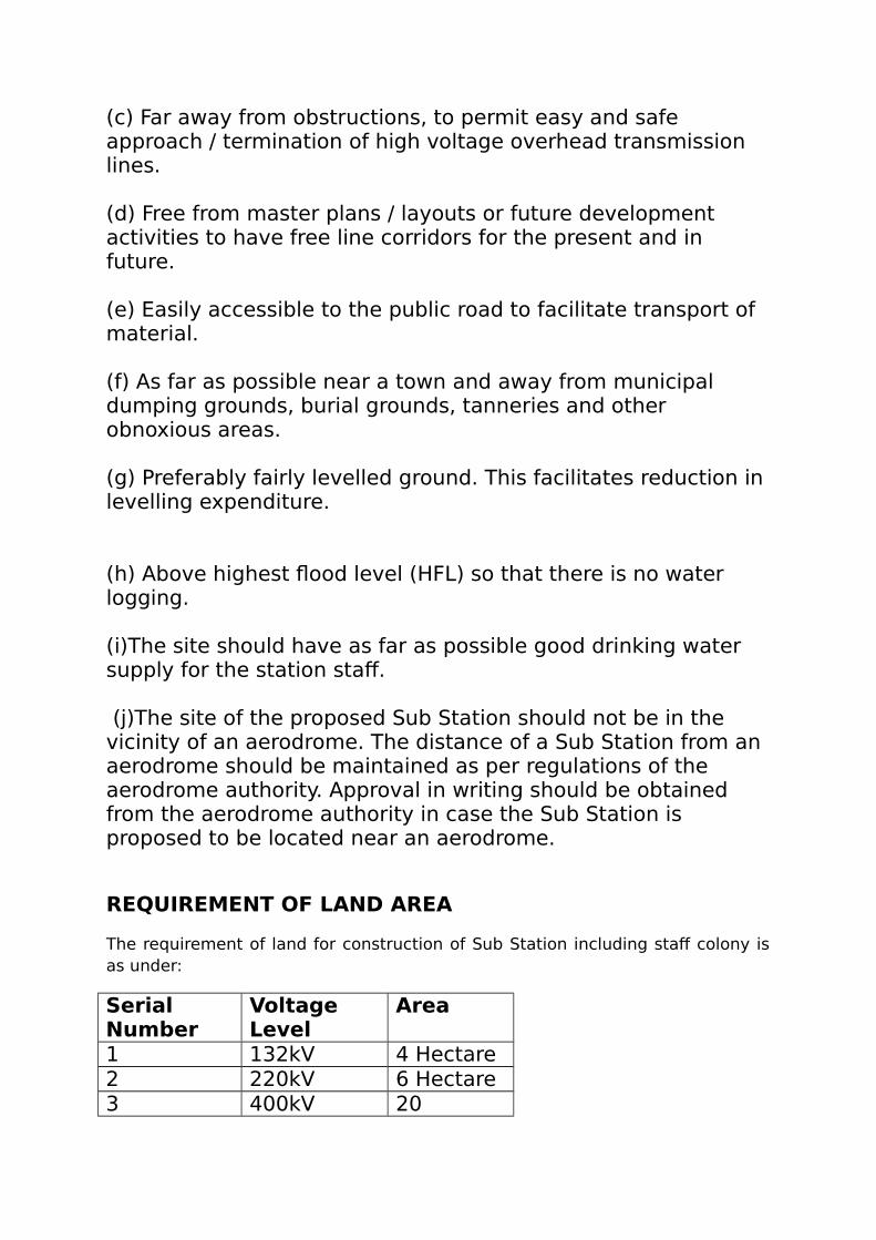
(c) Far away from obstructions, to permit easy and safe approach / termination of high voltage overhead transmission lines.
(d) Free from master plans / layouts or future development activities to have free line corridors for the present and in future.
(e) Easily accessible to the public road to facilitate transport of material.
(f) As far as possible near a town and away from municipal dumping grounds, burial grounds, tanneries and other obnoxious areas.
(g) Preferably fairly levelled ground. This facilitates reduction in levelling expenditure.
(h) Above highest flood level (HFL) so that there is no water logging.
(i)The site should have as far as possible good drinking water supply for the station staff.
(j)The site of the proposed Sub Station should not be in the vicinity of an aerodrome. The distance of a Sub Station from an aerodrome should be maintained as per regulations of the aerodrome authority. Approval in writing should be obtained from the aerodrome authority in case the Sub Station is proposed to be located near an aerodrome.
REQUIREMENT OF LAND AREA
The requirement of land for construction of Sub Station including staff colony isas under:
SerialNumber
VoltageLevel
Area
1 132kV 4 Hectare2 220kV 6 Hectare3 400kV 20

Hectare
CIVIL WORKS FOR SUBSTATION
GENERAL:
All structures, buildings, foundations etc., layout & other details shall be designed anddeveloped keeping in view the functional requirement of the line and sub-station facilities tomeet the major technical parameters and project parameter.
LICENSED PREMISES (SUBSTATIONS SITES):
1. Formation Levels: Formation Level (FL) of substations should be fixed minimum 600mm higher than the surroundings on the basis of the drainage conditions and theHighest Flood Level in the area.
2. Site Preparation: Necessary earth cutting/filling(spreading),leveling, compaction anddressing should be done. Backfilled earth should be free from harmful salts; viz,Sulphates,Chlorides and/or any Organic / Inorganic materials and compacted tominimum 95% of the Standard Proctor's Density (SPD) at Optimum Moisture Content(OMC). The subgrade for the roads and embankment filling shall be compacted tominimum 97% of the SPD at OMC.
3. Site Surfacing in Switchyard Area: Site surfacing should be carried out to provide
safe & hazard free high earth resistivity working area (switchyard)
prevent growth of weeds & grass within the working area.

The site surfacing will be restricted up to 2.0 m beyond the last structure /equipment
foundation.
A 100 mm thick base layer of lean concrete of 1:4:8 using coarse aggregate of 20 mm
nominal size shall be provided in the areas with covering with M-20 concrete layerwith minimum thickness of 50mm in the switchyard excluding roads, drains, cabletrenches etc.
30-40 mm Stone /Gravel spreading shall be done in areas presently in the scope of the
scheme.
No stone spreading shall for the time being done in the areas (bays) kept for future
expansion.
To hold the stone (gravel) from spreading out of the surfaced / gravel filled area, a 115
mm thick and 300 mm deep toe wall 25 mm above top of gravel shall be provided.
All visible portions of toe-wall shall be plastered & cement painted.
4. Outside Switchyard Area: Areas lying outside the switch yard should be landscaped,developed and maintained in a clean and presentable fashion.
WATER SUPPLY, SEWERAGE & DRAINAGE SYSTEM:
Water Supply & Sewerage:Water supply & sewerage system shall be designed to meet thetotal water requirement of the substations, facilities and emergency reserve for completeperformance of the works. The design and construction of septic tanks and soak pits shall besuitable for a minimum 100 users with a minimum 10 years span.
1. Design of Drainage: The concessionaire shall obtain rainfall data and design the stormwater drainage system including culverts, drains etc. to accommodate the most intenserainfall (in one hour period on an average of once per ten years.)
2. Slope of Drainage System: Invert level of drainage system at outfall point shall bedecided in such a way that any water over flow from water harvesting recharge shaftscan easily be discharged outside the substation boundary wall. For easy drainage ofwater :
Minimum slope of 1:1000 shall be provided from the ridge to the nearest drain.
Maximum spacing between two drains shall be less than 100 meter within the
switchyard

Side wall(s) of the drains shall be 25mm above the gravel level & covered with CI
grating;
Pipe drains shall be connected through manholes within intervals of maximum 30m;
Two portable pumps of adequate discharge capacity shall be provided for drainage of
water;
A sump pit of suitable capacity to hold water of at least 5 minutes discharge shall be
constructed at a suitable point.
RAINWATER HARVESTING:
Arrangements shall be made for rainwater harvesting in case the depth of water table is morethan 8.0 m from finished ground level. Rainwater harvesting shall be done by providing twonumbers recharge structures with bore wells suitably located within the sub-station with asuitable arrangement to connect the overflow from these structures with sump-pit.
ROADS, CULVERTS & PCC PAVEMENT / PARKING:
All internal roads, culverts and PCC pavements / parking within the sub-station area and
approach road from main PWD road to the sub-station main entry gate(s) should beconstructed as per state PWD specifications and as per layout in the Project.
All external / internal substation roads should be constructed to permit transportation of
heaviest of the substation equipment that can ever roll over the concerned road.
The main road leading to control room / switch yard / colony shall have a minimum 6 m
width with shoulder on either side.
1. Shoulders, Footpaths, & Side-walks: The shoulders / footpath / side-walk shall beprovided with C.C. (M-15) pre-cast kerbs on either side of the road. The top edge ofthe kerbs shall be battered. The kerb stones with top 20 cm wide shall be laid withtheir length running parallel to the road edge, true in line and gradient at a distance of30 cm from the road edge to allow for the drainage channel and shall project about12.5 cm above the latter as per PWD specifications.

2. Road Drainage: Adequate provision shall be made for road drainage. The channelstones with top 30 cm wide shall be laid in position in camber with finished roadsurface and with sufficient slope towards the road gully chamber.
3. Base Sub-Grade & Soling: Sub grade shall be compacted to achieve the density inaccordance with IS: 2720.The base course shall be extended on either side to at least15 cm (for switch yard roads) beyond the edge of the concrete pavement. The coarseaggregate used shall be crushed or broken stone or any naturally occurring aggregates.
4. Surfacing: The concrete to be placed shall conform to M-20 grade design mix usingapproved materials & methods as per IS: 10262. The concrete shall be distributed tosuch depth that when consolidated and finished, the slab thickness obtained is as persite requirement; but not less than 50 mm and equal at all points.
5. Paving/ Parking: Cement concrete paving / parking shall be provided as per layout.
TRANSFORMER FOUNDATION:
1. General Scope:
RCC foundations & plinths shall be designed having minimum Grade M-20 laid on base
concrete (1:4:8) of minimum thickness 100 mm along with a pylon support system forsupporting the fire fighting system for placing 315 MVA & 160 MVA Transformers.
The foundations of transformers and circuit breakers should be of block type.
Suitable arrangement for shifting the transformer from trailer like jacking etc. wherever
required should be made in plinth and in front of plinth on the road.
Adequate drainage outlets shall be provided and necessary slopes given to drain off rain
water/oil.
Suitable foundations shall be provided for all auxiliary equipment of the transformer
like radiators, fan supports etc. as required and the transformer plinth foundation shallmatch the equipment drawings.

If trench / drain crossings are required then suitable R.C.C. culverts shall be provided in
accordance with RRC standards / relevant IS.
2. Emergency Oil Evacuation System: Design & construction of Emergency OilEvacuation System should be suitable to the type of fire protection & emergency oildrainage system.
FIRE PROTECTION WALLS:
Fire protection walls are designed in order to protect 105 MVA single phase
Transformers of the 315 MVA unit against the effects of radiant heat and flying debrisfrom an adjacent fire in accordance with Tariff Advisory Committee (TAC) stipulations.
The partitions reduce the noise level of the transformers & should have adequate fire
resistance .
A minimum of 2m clearance shall be provided between the equipments and fire walls.
The building walls which act as fire walls shall extend at least 1 m above the roof in
order to protect it.
CABLE & PIPE TRENCHES:
1. General Scope:The top of trenches should be kept at least 25 mm above the gravellevel so that rain water does not enter the trench. Trench walls shall not foul with thefoundations and shall be designed for the following loads:
Dead load of 155 kg/m length of cable support +75 kg on one tier at outer edge
of tier
Earth pressure + uniform surcharge pressure
Trenches shall be constructed in RCC of M-20 grade. All metal parts inside the trench shouldbe connected to the earthing system.
2. Outdoor Cable Trenches: RCC cable trenches shall be constructed in the switchyardand fibre glass/pre-cast RCC removable covers with lifting arrangement, edge

protected with suitable galvanized angle iron designed to withstand self weight of topslab.
3. Indoor Cable Trenches: RCC indoor cable trenches shall be provided with 50X50X6mm GI angles grouted on the top edge of the trench wall for holding minimum 7 mmthick mild steel checkered plate covers (600 mm in length except at ends & bends)with lifting arrangement. ISMC GI channels of 75x40 mm shall also be grouted atdistances of 600 mm across the indoor cable trenches to support the checkered plates.
4. Trench Drainage: The trench bed shall have a slope of 1/500 along the run & 1/250perpendicular to the run. In case straight length exceeds 30 m, suitable expansion jointshall be provided at appropriate distances. The expansion joint shall run throughvertical wall and base of trench. All expansion joints shall be provided with approvedquality PVC water stops of approx. 230x5 mm size. Man holes shall be provided atinterval of not more than 30 meters. Sumps, as necessary, shall be provided at suitableplaces and at the dead end of all trenches. Sumps shall be provided with drainagepumps of adequate discharge capacity with all accessories for pumping out watercollected in the cable trenches. Cable trenches shall not be used as storm water drains.
5. Trench - Road Crossings: Suitable box culvert (Single span or multi spans) shall beprovided for any road crossing. The box culvert shall extend 1.5 m on each side ofroad and shall have 230-mm wide, 500 mm high brick parapet wall at ends.
FOUNDATIONS FOR CONSTRUCTION WORKS:
1. General: All the foundations except walls of switch house administrative and firehandling building shall be of Reinforced Cement Concrete.
2. Design Standards & Procedure: The design and construction of foundations and otherRCC structures shall be carried out as per IS specification.2 layers of reinforcement –one each on inner and outer side of wall and slabs having thickness of 150 mm andabove shall be provided. The tower and equipment foundations shall be checked for afactor of safety for normal condition and 1.65 for short circuit condition againstsliding, overturning and pullout.
3. Sliding & Overturning Stability: All sub-structures shall be checked for sliding andoverturning stability both during construction and operating conditions for variouscombinations of loads.
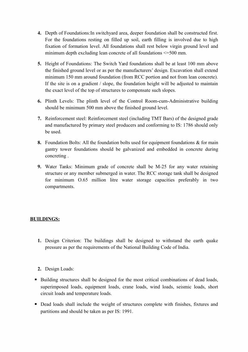
4. Depth of Foundations:In switchyard area, deeper foundation shall be constructed first.For the foundations resting on filled up soil, earth filling is involved due to highfixation of formation level. All foundations shall rest below virgin ground level andminimum depth excluding lean concrete of all foundations <=500 mm.
5. Height of Foundations: The Switch Yard foundations shall be at least 100 mm abovethe finished ground level or as per the manufacturers’ design. Excavation shall extendminimum 150 mm around foundation (from RCC portion and not from lean concrete).If the site is on a gradient / slope, the foundation height will be adjusted to maintainthe exact level of the top of structures to compensate such slopes.
6. Plinth Levels: The plinth level of the Control Room-cum-Administrative buildingshould be minimum 500 mm above the finished ground level.
7. Reinforcement steel: Reinforcement steel (including TMT Bars) of the designed gradeand manufactured by primary steel producers and conforming to IS: 1786 should onlybe used.
8. Foundation Bolts: All the foundation bolts used for equipment foundations & for maingantry tower foundations should be galvanized and embedded in concrete duringconcreting .
9. Water Tanks: Minimum grade of concrete shall be M-25 for any water retainingstructure or any member submerged in water. The RCC storage tank shall be designedfor minimum O.65 million litre water storage capacities preferably in twocompartments.
BUILDINGS:
1. Design Criterion: The buildings shall be designed to withstand the earth quakepressure as per the requirements of the National Building Code of India.
2. Design Loads:
Building structures shall be designed for the most critical combinations of dead loads,
superimposed loads, equipment loads, crane loads, wind loads, seismic loads, shortcircuit loads and temperature loads.
Dead loads shall include the weight of structures complete with finishes, fixtures and
partitions and should be taken as per IS: 1991.

Super-imposed loads in different areas shall include live loads, minor equipment loads,
cable trays, small pipe racks/hangers and erection, operation and maintenance loads.
Equipment loads shall constitute, if applicable, all load of equipments to be supported
on the building TAC or other relevant code.
For crane loads an impact factor of 30% and lateral crane survey of 10% of (lifted
weight + trolley weight)shall be considered in the analysis of frame according toprovisions of IS: 875. The horizontal surge shall be 5% of the static wheel load.
The wind loads and seismic forces shall be computed. Response spectrum method shall
be used for the seismic analysis using at least first five modes of vibration. Wind andSeismic force shall not be considered to act simultaneously.
For temperature loading, the total temperature variation shall be considered as 2/3 of the
average maximum annual variation in temperature. The average maximum annualvariation in temperature for the purpose shall be taken as the difference between themean of the daily minimum temperature during the coldest month of the year and meanof daily maximum temperature during the hottest month of the year. The structure shallbe designed to withstand stresses due to 50% of the total temperature variation.
Floors / slabs shall be designed to carry loads imposed by equipment, cables, piping,
travel of maintenance trucks and equipment and other loads associated with thebuilding. In general, floors shall be designed for live loads as per relevant IS and cableand piping loads of no less than 5kN / sq. m. hanging from the underside. Forconsideration of loads on structures, IS: 875, “Code of practice for structural safety ofbuildings” shall be followed. The following minimum superimposed live loads shall,however, be considered for the design:
i) Roof 150kg / m2 for accessible roofs & 75kg / m2 for non accessible roofs
ii) RCC floors 500 kg /m2 for non-accessible roofs. 2 for offices and minimum 1000kg/m2 for equipment floors or actual, if higher than 1000 kg / m2
iii) Toilet Rooms 200 kg / m2.
iv) Walkways 300 kg / m2
3. DG Building Cum Fire Fighting Pump House and RCC Water Storage Tank:
The DG and FF buildings designed to accommodate up to [two (2)] DG sets, motors
/pumps and a permanent crane, hoist and service trucks mounted on suitable steelstructure below the ceiling for servicing, lifting and maintenance of the heavyequipment shall be constructed
Arrangement shall be made to drain the spill oil from oil diesel operated equipment
along the periphery for collection. Piping shall be provided for conveying oil from thestorage tank (common for all diesel / engines) to individual fuel tank of engine.

4. Storm Water Drainage for Buildings: The building drains shall be provided for thecollection of storm water from the roofs in junction boxes and these boxes shall drainto the main drainage system of the station. Cast iron / PVC rain water down comers(minimum 100mm diameter) with water tight joints shall be provided to drain off therain water from the roof. These shall be suitably concealed with masonry work orcement concrete or cladding materials. All drains inside the buildings shall haveminimum 40 mm thick grating covers.
5. Brick Work: All brickwork shall strictly be done according to the P.W.D.specifications.
6. Damp Proof Course: On outer walls horizontal DPC shall be provided at level withplinth protection and on inner face vertical DPC 20 mm thick shall be provided. Onall inner walls horizontal DPC shall be provided at floor/plinth level. In earth quakeresistant structures DPC may be substitute by 230mm x230mm thick M-20 RCCplinth beams
7. Painting and Finishing: All paints & allied materials shall be of superior quality,conform to the relevant Indian Standards and of approved brands and shades.
FLOORING:
The flooring of Control Room-cum-Administrative building except conference room,
control room, reception hall & reception stairs shall be made of Kota stone.
Pre-polished granite stone slabs, 19 mm thick (3/4”) flooring shall be provided in
reception hall, stairs of reception hall, control room and conference rooms.
Anti-skid tiles 300 x 300 x 7.7 mm flooring in toilets and pantry.
Anti skid floor tiles of reputed makes having minimum 300 x 300 mm nominal size and
7.7 mm thick preferably in Beige colour shall be provided in the toilets.
Heavy duty ironite concrete floor hardener shall be provided in DG Building cum Fire
Fighting Pump House.

Entire area around the Control Room-Cum-Administrative building, DG- cum-fire
fighting building, Security Hut and the Driver’s room shall be provided with PCCpaving.
DOORS AND WINDOWS:
Aluminium frames / doors / windows / ventilators (single & double leaf) consisting framework including vertical styles, top rails, lock (middle) rails and bottom rails with metalfastener & screws shall be fitted with nuts & bolts or using plastic plugs & screws. TheAluminium doors & windows shall be fitted with minimum 5.5 mm thick glass of reputedmake with high-class rubber gaskets & beading complete so to make the glass airtight. Thetoilet doors shall, however, be fitted with prelaminated board panels of appropriate size withAluminium beading to make it airtight.
ROLLING SHUTTERS:
Rolling shutters with suitable operating arrangement according to size & weight shall beprovided in buildings to facilitate handling and transportation of equipment.
TOILET & PANTRY SANITARY FITTINGS:
All the water closets, wash basins, squatting pans etc. shall be of vitreous China clay in whitecolor, (first quality) as per IS: 2556. The water closet in officer’s toilet shall be European typewith single / double siphon and low-level cistern. The toilets & pantry shall be provided withthe best Indian make 20 mm diameter, 600 mm long towel rails and other normal fixtures,firmly fixed in position with plastic plugs and CP brass screws. All fixtures / fittings shall bechromium plated of good durable quality. The pantry shall be provided with reputed makewhite vitreous chinaware sink of size 600 x 450 x 250 mm or more with complete fittingsincluding 40 mm CP brass waste and PVC pipe chromium plated brass tap etc.

SWITCH - YARD FENCING AND GATES:
Fencing & Gates shall be provided for Switchyard area as per General Electrical Layout Plan.Chain link fence fabric shall have size 75 mm; coated wire shall be of 3.15 mm diameterhaving zinc galvanizing after weaving. The barbed wire shall be of 12 SWG galvanized steelwith its weight 155-186 gm/m length of wire. Maximum distance between two barbs shall be75mm. The barbs should carry four points and shall be formed by twisting two point wires,each two turn tightly round one line wire making altogether 4 complete turns. The barbs shallhave a length of not less than 13 mm and not more than 18 mm. The points shall be sharp andwell pointed and single strand galvanized steel wire.
BOUNDARY AND RETAINING WALLS:
A Boundary wall shall be constructed all around the entire substation land. The front wallshall be 1.4 m. high and in addition 0.600 m galvanized iron grill & the boundary wall on theother three sides shall be 1.8 m with 0.600 m U/C barbed wire fencing over the wall.
SAFETY CLEARANCES
“Safety Working Clearance” is the minimum clearance to bemaintained in air between the live part of the equipment onone hand and earth or another piece of equipment or conductor(on which it is necessary to carry out the work) on the other.
The various equipments and associated / required facilitieshave to be so arranged within the substation that specifiedminimum clearances are always available from the point ofview of the system reliability and safety of operating personnel.These include the minimum clearances from live parts to earth,between live parts of adjacent phases and sectional clearancebetween live parts of adjacent circuits / bays. It must beensured that sufficient clearance to ground is also availablewithin the Sub Station so as to ensure safety of the personnelmoving about within the switchyard
The Table below gives the minimum values of clearancesrequired for Sub Stations upto 400 kV:

Nominalsystemvoltage
Highestsystemvoltage
Lighteningimpulselevel
Switchingimpulselevel
Minimumclearance (mm)
Safetyclearance(mm)
Groundclearance(mm)
Betweenphaseandearth
Betweenphases
11 12 70 - 178 229 2600 370033 36 170 - 320 320 2800 3700132 145 550
650- 1100
130011001300
37003800
46004600
220 245 9501050
- 19002100
19002100
43004600
55005500
400 420 1425 1050(Ph – E)1575(Ph –Ph)
3400--
--4200
6400 8000
INSULATION CO-ORDINATION
Insulation co-ordination is the correlation of insulation of electrical equipments and circuit with the characteristic of protective devices such that the insulation is protected from excessive over-voltages.
The requirements need to be satisfied:
(i) a suitable basic insulation level(BIL) is to be selected (ii) it is to be ensured that the breakdown voltage of all
insulation in the station will exceed the BIL(iii) choosing proper protective devices providing good
protection at a viable cost
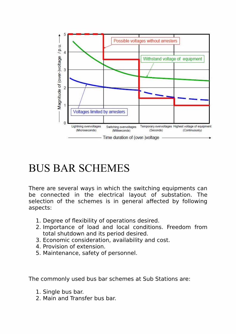
BUS BAR SCHEMES
There are several ways in which the switching equipments canbe connected in the electrical layout of substation. Theselection of the schemes is in general affected by followingaspects:
1. Degree of flexibility of operations desired.2. Importance of load and local conditions. Freedom from
total shutdown and its period desired.3. Economic consideration, availability and cost.4. Provision of extension.5. Maintenance, safety of personnel.
The commonly used bus bar schemes at Sub Stations are:
1. Single bus bar.2. Main and Transfer bus bar.

3. Double bus bar.4. Double main and transfer bus bar.5. One and a half breaker scheme.
SINGLE BUS-BAR ARRANGEMENT:
This is the simplest switching scheme in which each circuit is provided with one circuit breaker. This arrangement offers little security against bus bar faults and no switching flexibility resulting into quite extensive outages of bus bar and frequent maintenance of bus bar isolator(s). The entire Sub Station is lost in case of a fault on the bus bar or on any bus bar isolator and also in case of maintenance of the bus bar. Another disadvantage of this switching scheme is that in case of maintenance of circuit breaker, the associated feeder has also to be shutdown.
MAIN AND AUXILIARY BUS ARRANGEMENT:
This is technically a single bus bar arrangement with an additional bus bar called “Auxiliary bus” energized from main

bus bars through a bus coupler circuit, i.e., for ‘n’ number of circuits, it employs ‘n + 1’ circuit breakers. Each circuit is connected to the main bus bar through a circuit breaker with isolators on both sides and can be connected to the auxiliary bus bar through an isolator. The additional provision of bus coupler circuit (Auxiliary bus)facilitates taking out one circuit breaker at a time for routine overhaul and maintenance without de – energizing the circuit controlled by that breaker as that circuit then gets energized through bus coupler breaker.As in the case of single bus arrangement, this scheme also suffers from the disadvantages that in the event of a fault on the main bus bar or the associated isolator, the entire substation is lost. This bus arrangement has been extensively used in 132 kV Sub Stations.

DOUBLE BUS BAR ARRANGEMENT:
In this scheme, a double bus bar arrangement is provided. Eachcircuit can be connected to either one of these bus bars through respective bus bar isolator. Bus coupler breaker is also provided so that the circuits can be switched on from one bus to the other on load. This scheme suffers from the disadvantage that when any circuit breaker is taken out for maintenance, the associated feeder has to be shutdown.This Bus bar arrangement was generally used in earlier 220 kV sub stations.

DOUBLE MAIN AND AUXILIARY BUS BAR ARRANGEMENT:
The limitation of double bus bar scheme can be overcome by using additional Auxiliary bus, bus coupler breaker and Auxiliary bus isolators. The feeder is transferred to the Auxiliarybus during maintenance of its controlling circuit breaker withoutaffecting the other circuits.This Bus bar arrangement is generally used nowadays in 220 kV sub stations.
ONE AND A HALF BREAKER ARRANGEMENT:

In this scheme, three circuit breakers are used for controlling two circuits which are connected between two bus bars. Normally, both the bus bars are in service. A fault on any one ofthe bus bars is cleared by opening of the associated circuit breakers connected to the faulty bus bar without affecting continuity of supply. Similarly, any circuit breaker can be taken out for maintenance without causing interruption. Load transferis achieved through the breakers and, therefore, the operation is simple. However, protectiverelaying is somewhat more involved as the central (tie) breaker has to be responsive to troubles on either feeder in the correct sequence. Besides, each element of the bay has to be rated for carrying the currents of two feeders to meet the requirement ofvarious switching operations which increases the cost. The breaker and a half scheme is best for those substations which handle large quantities of power and where the orientation of out going feeders is in opposite directions. This scheme has been used in the 400 kV substations.

Bus-bar Materials
Sl no. Description Bus Bar and Jumper Material

1 400 kV Main Bus 114.2 mm dia. Aluminium pipe
2 400 kVequipmentinterconnection
114.2 mm dia. Aluminium pipe
3 400 kV overheadbus & droppersin allbays.
Twin ACSR Moose
4 220 kV Main Bus Quadruple / Twin ACSR Zebra / TwinAAC Tarantulla
5 220 kV AuxiliaryBus
ACSR Zebra
6 220 kVequipmentinterconnection
Twin ACSR Zebra / Single ACSRZebra
7 220 kV overheadbus & droppersin allbays.
Twin ACSR Zebra / Single ACSRZebra
8 132 kV Main Bus ACSR Zebra
9 132 kV AuxiliaryBus
ACSR Panther
10 132 kVequipmentinterconnection
ACSR Zebra / ACSR Panther
BAY LAYOUT OF A 440 kV SUBSTATION:

Details about numbers of bays and numbers ofequipments required:
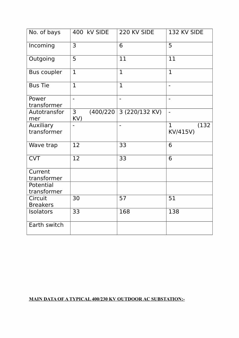
No. of bays 400 kV SIDE 220 KV SIDE 132 KV SIDE
Incoming 3 6 5
Outgoing 5 11 11
Bus coupler 1 1 1
Bus Tie 1 1 -
Powertransformer
- - -
Autotransformer
3 (400/220KV)
3 (220/132 KV) -
Auxiliarytransformer
- - 1 (132KV/415V)
Wave trap 12 33 6
CVT 12 33 6
CurrenttransformerPotentialtransformerCircuitBreakers
30 57 51
Isolators 33 168 138
Earth switch
MAIN DATA OF A TYPICAL 400/230 KV OUTDOOR AC SUBSTATION:-

OPERATING VOLTAGE 400 KV 230 KV
Rated current 2000A 2000A
Maximum short circuit current inbus bar
40 KA 40 KA
Minimum phase to phase clearance 5.75 m 2.5 m
Minimum phase to earth clearance 3.65 m 2.0 m
Number of horizontal bus bar of firstlevel above ground
2 2
Height of tubular bus bar of firstlevel above ground
7 m 6 m
Height of tubular bus bar of secondlevel above ground
13 m 4 m
Tubular aluminum bus bar A1 ASTMB241
4”IPS 4”IPS
SWITCHYARD:Switchyard may be defined as the combination of various switching, measuring and protecting devices, supported with structures & hardwares that meant to establish the flow of power in an electrical network.
FUNCTIONS OF A SWITCHYARD:
1. Providing a link between Generating Plant and TransmissionSystem. 2. Stepping up or stepping down voltage as required 3. Controlling reactive power which has effect on quality of power. 4. Protection of substation and its components.

MAIN COMPONENTS OF A SWITCHYARD:
Transformer. Circuit Breaker. Current Transformer (CT). Voltage Transformer (VT). Capacitor Voltage Transformer (CVT). Isolators. Earthing Switch. Lightning Arrester. Wave Trap. Bus Bar & Clamp Fitting.
TRANSFORMERS
Transformer is a static piece of apparatus with two ormore windings which, by electromagnetic induction, transformsa system of alternating voltage and current into another systemof voltage and current usually of different values and at thesame frequency for the purpose of transmitting electricalpower.
Normally during the design of a substation a few types oftransformers are needed for smooth and flexibleoperation.They are :-
1. Power Transformersa. Auto Transformers (with tertiary winding and OLTC)b. Two winding Transformers (mainly for auxiliary
purposes)2. Transformers for metering and protection
a. Current Transformers(C.T.)b. Potential Transformers(P.T.)c. Capacitive Voltage Transformers (C.V.T)
Two Winding Transformers :-
The two-winding power transformer has two separate electricalwindings. It is used to interconnect two electrical networks with

typically different voltage levels. Two-winding powertransformers with rating bigger than 5MVA are typically star(wye) connected or delta connected, and less frequently, zigzagconnected. Such power transformers introduce a fixed phaseangle displacement (i.e. phase angle shift) Θ between the twowindings. The commonly used two winding connections areshown below:-
Dd6 or Dd0 (delta/delta):-This is an economical connection forlarge low voltage transformers in which insulation problem isnot urgent as it increases the number of turns per phase andreduces the necessary sectional area of conductors. But it canmeet large unbalanced load with ease as the third harmoniccurrents are damped out in closed mesh.
Dy or Yd (Delta/star or Star/delta):- It is the most commonconnection for power supply transformers.It has the advantageof star point for mixed loading and delta to carry the thirdharmonic currents.
Yy (star/star):- This is the most economical connection for smallhigh voltage transformers and as the number of turns perphase is minimum the amount of insulation is minimum.But thistype of connection is favorable for shell type transformer and inother cases presence of tertiary winding is essential forstabilizing the neutral.
Yz or Zy (star/zigzag or Zigzag/star):- This type of connection isdone where delta connection is mechanically weak on accountof large no. of turns for small copper cross sections.

AUTO TRANSFORMERS:-
An auto-transformer is a power transformer in which at leasttwo windings have a common part. Auto-transformers are mostoften used to interconnect EHV and/or HV networks. It can beshown that they are less expensive than normal two-windingtransformers if the voltage difference between the twowindings (e.g. networks) is relatively small . For power systemapplications auto-transformers are typically used with a third,delta connected winding.With voltage ratio of 2:1 there may bea 30-35% saving of cost from that of a two windingtransformer.But they are not used when the voltage ratioexceeds 3:1 as the disturbances in one side will affect the otherside pretty dangerously due to the direct electrical connectionbetween two sides.

315 MVA 400 KV autotransformer
The autotransformers are provided with a tertiary winding for afew reasons. They are :-
a. For additional load which for some reason must be keptinsulated from the secondary.
b. To supply phase compensating devices whose voltage maynot be equal to primary or secondary voltage andoperated at different voltages.
c. To suppress harmonic volatges (when connected in delta)and to limit voltage unbalance where load isasymmetrical.
Due to unbalance loading and presence of triplen harmonicstransformer operation may be affected considerably.Thus thetertiary winding is connected in delta to suppress th harmonicvoltage and to detain the flow of triplen harmonic currents inthe lines.(If both primary and secondary are star connectedthen harmonic currents are divided according to relativeimpedance).

CURENT TRANSFORMER
This instrument transformer is connected to ac power circuit. The secondary winding of the CTs are fed to indicating, metering instrument & and protective relays .CTs are connectedto power circuit to watch over current flow & over power load. In CT primary
Winding is directly connected in series with the power circuit & it is single turn. In the secondary winding number of turns is more if the measuring current is more. The ratio of primary & secondary current is known as CT transformation ratio. The main purpose of use CTs:
1. Differential Protection2. Bus bar protection3. Backup protection for over current and earth fault4. Metering
VOLTAGE TRANSFORMER
Potential transformers serve a number of functions in a power system. They are mainly used for stepping down of high magnitude voltage to a safe value for incorporate measuring and protection logics. They are used for metering and instrumentation purposes in power system. These are also usedin relay protective system. In conjunction with current transformers (CTs) they can be used in measuring power.

CAPACITIVE VOLTAGE TRANSFORMER
The CVT is used for line voltage meter, synchroscope, protective relays and tariff meters. The performance of CVT is inferior to electromagnetic voltage transformer. Performance of CVT is greatly affected by variation of frequency.
CIRCUIT BREAKERS
A circuit breaker is a mechanical device designed to close oropen contact members, thus, closing or opening an electricalcircuit breaker, under normal or abnormal conditions. It consistof fixed & moving contacts which touch each other undernormal conditions i.e. when CB is closed, considerable amountof energy is stored in the spring contacts which are heldtogether by toggles. CB is provided with trip coil connected to a

relay designed to open automatically under fault condition.Only small pressure is required to be applied on protectiverelay. It trips & the potential energy of the springs is released &contacts open in fraction of seconds.
Various types of C.B are used :1 .SF6 circuit breaker
2. Oil circuit breaker
3. Air blast circuit breaker
4. Vacuum circuit breaker
MODES OF ARC EXTINCTION 1) HIGH RESISTANCE INTERRUPTION- In this process thearc is increased by lengthening and cooling to such anextent that the system voltage is no longer able to maintainthe arc and the arc gets extinguished. This technique isemployed in air break circuit breakers and D.C circuitbreaker.2) LOW RESISTANCE OR ZERO POINT INTERRUPTION- Inthis process the arc gets extinguished at natural current zeroof the alternating current wave and is prevented fromrestriking again by rapid build- up of dielectric strength ofthe contact space. This process is employed in almost all A.Ccircuit breakers
SF6 Circuit Breaker
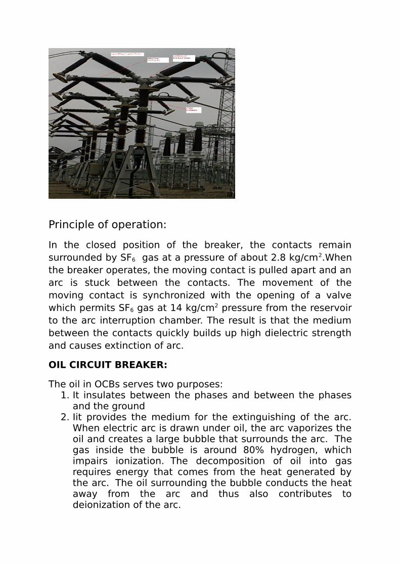
Principle of operation:
In the closed position of the breaker, the contacts remainsurrounded by SF6 gas at a pressure of about 2.8 kg/cm2.Whenthe breaker operates, the moving contact is pulled apart and anarc is stuck between the contacts. The movement of themoving contact is synchronized with the opening of a valvewhich permits SF6 gas at 14 kg/cm2 pressure from the reservoirto the arc interruption chamber. The result is that the mediumbetween the contacts quickly builds up high dielectric strengthand causes extinction of arc.
OIL CIRCUIT BREAKER:
The oil in OCBs serves two purposes:1. It insulates between the phases and between the phases
and the ground2. Iit provides the medium for the extinguishing of the arc.
When electric arc is drawn under oil, the arc vaporizes theoil and creates a large bubble that surrounds the arc. Thegas inside the bubble is around 80% hydrogen, whichimpairs ionization. The decomposition of oil into gasrequires energy that comes from the heat generated bythe arc. The oil surrounding the bubble conducts the heataway from the arc and thus also contributes todeionization of the arc.

Main disadvantage of the oil circuit breakers is the flammabilityof the oil, and the maintenance necessary to keep the oil ingood condition (i.e. changing and purifying the oil).
Two main types of oil circuit breakers are:(a)Bulk oil circuit breaker: no special means is available forcontrolling the arc and the contacts are directly exposed to thewhole of the oil in the tank.(b)Low oil circuit breaker: use minimum amount of oil. Oil isused only for arc extinction. Insulation is provided by air orporcelain or organic insulating material.
Air Blast circuit breaker
These breakers employs a high pressure air blast as an arcquenching medium. The contacts are opened in a flow of airblast established by the opening of blast valve. The blast coolsthe arc and sweeps away the arcing products to theatmosphere. This rapidly increases the dielectric dtrength ofthe medium between the contacts and prevents from re-establishing the arc. Consequently, the arc is extinguished.
Types of Air blast circuit breakers:(a)Axial blast type: air-blast directed along the arc path.(b)Cross blast type: air blast directed at right angles to thearc path.(c)Radial blast type: air blast directed radially to arc path.
Vacuum circuit breaker:
When the breaker operates, the moving contact separate fromthe fixed contact and an arc is struck between the contacts.The arc is quickly extinguished because the metallic vapours,electrons and ions produced during arc diffuse in a short timeand seized by the surface of moving and fixed members andshields. Due to fast rate of recovery of dielectric strength ofvacuum, arc extinction occurs.

ISOLATORS
An isolator/disconnecting switch is used to open some given parts of a power circuit after switching off the load by means of a CB. This isolator serves only for preventing the voltage from being applied to some given section of the bus bars in a switchgear installation or to one or another piece of apparatus in the installation.
In some cases isolators are used as a circuit breaking device but their purposes are strictly limited.
EARTHING SWITCH
Earth switch discharges the capacitive voltage stored in line on generator side in the isolated system just after opening of CB &isolator. When earth switch is connected to the isolated but charged system it discharges the stored energy to earth, so that maintenance work can be carried out either in line on generator side. Earth switches should be operated only when the isolators are open.
All earth switches can be operated manually. Semaphore indicator can be seen for position feedback (on/off) in switchyard control panel.
LIGHTNING ARRESTER

Lighting arrestor is a device, which protects overhead lines and other electrical apparatus viz, transformer, and generator against lightning. Basically it consists of an arc gap and a non-linear resistor. Whenever there is a lightning, the voltage strikesthe transmission line and the surge voltage begins to flow alongthe line. Under this condition the value of non-linear resistor decreases to a low value thus providing a low resistance path for the voltage wave. Thus the surge wave directly passes to the earth without affecting any equipment in the line. It is also seen that if there is a positively charge cloud over a transmission line, then it will produce a negative charge by electrostatic induction. This negative charge will however remain right under the cloud and portion of the line away from that cloud will be positively charged. This positive charge will flow gradually to earth slowly through insulator and metallic parts. Thus the charge that remains is the negative charge. Thischarge then flows along the transmission line as surge wave

and damages the equipment. Thus the lightning arrestor provides protection against this wave.
WAVE TRAP
Wave trap is used for protection of the transmission line and communication between the Substations:
VHF signal is transmitted from one end to another throughthe same power line.
Sends inter-trip signal to the other end CBs so that fault can be isolated at the earliest time.
Protection of Busbars
Busbars in the substation form important link between theincoming and outgoing circuits. If a fault occurs on a busbars,considerable damage and disruption of supply will occur unlesssome form of quick-acting automatic protection is provided toisolate the faulty busbar.
The busbar zone, for the purpose of protection, includes notonly the busbars themselves but also the isolating switches,circuit breakers and the associated connections.

The two most commonly used schemes for busbar protectionare
1. Differential protection2. Under voltage protection.3. Over- current protection with directional element.4. Combined Earth fault and phase fault protection.5. Frequency relay.
1. Differential protection: The basic method for busbarprotection is the differential schemes in which currententering and leaving the bus are totalised. During normalload condition, the sum of these currents is equal to zero.When a fault occurs, the fault current upsets the balanceand produces a differential current to operate a relay.
Under normal load condition or external fault condition,the sum of the current entering the bus is equal to thoseleaving it and no current flows through the relay. If a faultoccurs within the protective zone, the currents enteringthe bus will no longer be equal to those leaving it. Thedifference of these currents will flow through the relay andcause the operation of the each of the circuit breaker.
2. Combined earth fault and phase fault protection : itis convenient to incorporate phase fault and earth faultrelay in a combined phase fault and earth fault protection.The earth relay has low current setting and operates under

earth or leakage faults only. The overload relays have highcurrent setting and are arranged to operate against faultsbetween the phases. In the absence of earth fault the vector sum of threeline currents is zero. Hence the vector sum of threesecondary currents is also zero.Ias+Ibs+Ics=0 so during normal condition no current flowsthrough earth fault relay and the relay will not operate.However in the presence of earth fault the condition isdisturbed and Ias+Ibs+Ics≠0 , so the current flows throughearth fault relay and if this current is above the pickupvalue, relay operates. For any phase-phase fault the increase in current ofphase cause corresponding increase in respectivesecondary current. If the current becomes more than pickup current , relay operates.
3. Under voltage relays: under voltage protection isprovided for bus-bars, rectifiers, transformers etc. suchprotection is given by means of under voltage relays.Under voltage relays are necessary for voltage control anrreactive power control of network buses and load buses.Under voltage relays can have instantaneouscharacteristic or inverse characteristic depending uponthe construction and design. Inverse time undervoltagerelays have inverse characteristic, their operating time

reduces with reduction in voltage. Induction disc typeconstruction is used for inverse undervoltage relay.
4. Directional power relay : this type of relay operateswhen power in the circuit flows in a specific direction. Adirectional power relay is so designed that it obtains itsoperating torque by the interaction of magnetic fieldsderived from both voltage and current source of the circuitit protects.
In this type of relays
Torque developed α VI cosф α power in the
circuit.
When the power in the circuit flows in the normal direction, thedriving torque and the restraining torque help each other toturn away the moving contact from the fixed contacts.Consequently, the relay remains inoperative. However reversalof current in the circuit reverses the direction of driving torqueon the disc.

NEGATIVE SEQUENCE RELAY:
Negative sequence overcurrent relays are used to detectunbalanced load on a generator which may cause excessiverotor heating. The relay is also used to detect unbalanced loadcurrents in motor.
The advantage of the negative sequence current over zerosequence currentis that mutually coupled parallel line currents are notinfluencing the measurement and that only the three phasecurrents are used as inputs, i.e. the neutral current is notneeded
HARMONIC RESTRAINT RELAY:
1. The relay is used to delay earth fault protection in solidlyearth power system.
2. The most typical application is as a sensitive back-upprotection in a transformer neutral or at a power line.
3 . When a transformer is switched in and energized,a highinrush currentusually appears. It can reach a peak value of several times thetransformer’s rated current, and it is gradually damped to anormal magnetizing current of some percent of rated current.
4. The transformer inrush current is heavily distorted and has ahigh percentage of second harmonic, which prevents relayoperation.
• Rated frequency 50 or 60 Hz
• Operation blocked by 2nd harmonic component >20% of thefundamental current
• Operate time 50 - 70 ms at 3 x pick-up
• Reset ratio >90%

• Variants available with definite or inverse time delayedoutput.
Transformer Failures:-
Failures in transformers can be classified into,
• winding failures due to short circuits (turn-turn faults, Phase-phase faults, phase- ground, open winding)
• Core faults (core insulation failure, shorted laminations)
• Terminal failures (open leads, loose connections, short Circuits)
• On-load tap changer failures (mechanical, electrical, short Circuit, overheating)
• Abnormal operating conditions (over fluxing, overloading, overvoltage)
• External faults
Types of abnormal conditions:-
Incipient faults below oil level resulting in decomposition of oil. Faults between phase and between phases to ground.
Large internal faults phase to phase. Phase to ground below oil level.
Faults in tap changer.
Saturation of magnetic circuit.
Earth faults.
Over loads.
High voltage surges due to lighting switching.

Protection against Internal fault:-
Buchholz relay ( gas actuated relay):-
Buchholz relay is a gas-actuated relay installed in oilimmersed transformers for protection against all kinds offaults.Named after its inventor, Buchholz, it is used to give an alarmincase of incipient (i.e.slow-developing) faults in the transformer and todisconnect the transformer from the supply in the event of severeinternal faults. It is usually installed in the pipe connecting theconservator to the main tank. It is a universal practice to useBuchholz relays on all such oil immersed transformers having ratingsin excess of 750 kV
BUCHHOLZ – alarms for:

� Local winding overheating - alarm
� Local core overheating (short circuited laminations)
� Bad contacts or joints
� Partial discharge
� Broken down core bolt insulation
Operation. The operation of Buchholz relay is as follows :
(i) In case of incipient faults within the transformer, the heat due to fault causes the decomposition of some transformer oil in the main tank. The products of decomposition contain more than 70% of hydrogen gas. The hydrogen gas being light tries to go into the conserva-tor and in the process gets entrapped inthe upper part of relay chamber. When a predetermined amount of gas gets accumulated, it exerts sufficient pressure on the float to cause it to tilt and close the contacts of mercury switch attached to it. This completes the alarm circuit to sound an alarm.
(ii) If a serious fault occurs in the transformer, an enormous amount of gas is generated in the main tank. The oil in the main tank rushes towards the conservator via the Buchholz relay and in doing so tilts the flap to close the contacts of mercury switch. This completes the trip circuit to open the circuit breaker controlling the transformer.
Advantages
(i) It is the simplest form of transformer protection.
(ii) It detects the incipient faults at a stage much earlier than is possible with other forms of protection.
Disadvantages
(i) It can only be used with oil immersed transformers equippedwith conservator tanks.

(ii) The device can detect only faults below oil level in the transformer. Therefore, separate protection is needed for connecting cables.
EARTH FAULT PROTECTION:-
An earth-fault usually involves a partial breakdown of winding insulation to earth. The resulting leakage current is considerably less than the short-circuit current. The earth-fault may continue for a long time and cause considerable damage before it ultimately develops into a short-circuit and removed from the system. Under these circumstances, it is profitable to employ earth-fault relays in order to ensure the disconnection of earth-fault or leak in the early stage. An earth-fault relay is essentially an overcurrent relay of low setting and operates as soon as an earth-fault or leak develops. One method of protection against earth-faults in a transformer is the core-balance leakage protection shown in figure below:-
The three leads of the primary winding of power trans- former are taken through the core of a current transformer which carries a single secondary winding. The operating coil of a relayis connected to this secondary. Under normal conditions (i.e. nofault to earth), the vector sum of the three phase currents is zero and there is no resultant flux in the core of current transformer no matter how much the load is out of balance. Consequently, no current flows through the relay and it remains

inoperative. However, on the occurrence of an earth-fault, the vector sum of three phase currents is no longer zero. The resultant current sets up flux in the core of the C.T. which induces e.m.f. in the secondary winding. This energises the relay to trip the circuit breaker and disconnect the faulty transformer from the system.
RESTRICTED EARTH FAULT PROTECTION
Conventional earth fault protection using overcurrent elements fails to provide adequate protection for transformer windings. This is particularly the case for a star-connected winding with an impedance-earthed neutral. The degree of protection is verymuch improved by the application of restricted earth fault protection (or REF protection). This is a unit protection scheme for one winding of the transformer (mainly for secondary winding phase to earth fault). It can be of the high impedance type , or of the biased low impedance type. For the high-impedance type, the residual current of three line current transformers is balanced against the output of a current transformer in the neutral conductor. In the biased low-impedance version, the three phase currents and the neutral current become the bias inputs to a differential element. The system is operative for faults within the region between currenttransformers, that is, for faults on the star winding in question. The system will remain stable for all faults outside this zone. Restricted earth fault protection is often applied evenwhen the neutral is solidly earthed. Since fault current then remains at a high value even to the last turn of the winding , virtually complete cover for earth faults is obtained. This is an improvement compared with the performance of systems that do not measure the neutral conductor current. Earth fault protection applied to a delta-connected or unearthed star winding is inherently restricted, since no zero sequence components can be transmitted through the transformer to the
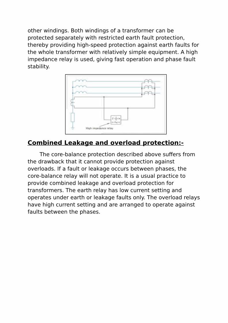
other windings. Both windings of a transformer can be protected separately with restricted earth fault protection, thereby providing high-speed protection against earth faults forthe whole transformer with relatively simple equipment. A high impedance relay is used, giving fast operation and phase fault stability.
Combined Leakage and overload protection:-
The core-balance protection described above suffers from the drawback that it cannot provide protection against overloads. If a fault or leakage occurs between phases, the core-balance relay will not operate. It is a usual practice to provide combined leakage and overload protection for transformers. The earth relay has low current setting and operates under earth or leakage faults only. The overload relayshave high current setting and are arranged to operate against faults between the phases.

In this system of protection, two overload relays and one leakage or earth relay are connected as shown. The two overload relays are sufficient to protect against phase-to-phase faults. The trip contacts of overload relays and earth- fault relayare connected in parallel. Therefore, with the energising of either overload relay or earth relay, the circuit breaker will be tripped.
Biased Differential Protection:-
A simple rule of thumb is that the CT’s on any wye winding of a power transformer should be connected in delta, and the CT’s on any delta winding should be connected in wye. This rule may be broken, but it rarely is; for the moment let us assume that it is inviolate. Later, we shall learn the basis for this rule. The remaining problem is how to make the required interconnection between the CT’s and the differential relay.
Two basic requirements that the differential-relay connections must satisfy are:
(1) the differential relay must not operate for load or external faults; and
(2) the relay must operate for severe enough internal faults.
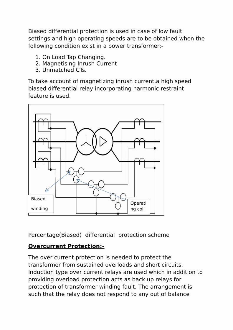
Biased differential protection is used in case of low fault settings and high operating speeds are to be obtained when thefollowing condition exist in a power transformer:-
1. On Load Tap Changing.2. Magnetising Inrush Current3. Unmatched CTs.
To take account of magnetizing inrush current,a high speed biased differential relay incorporating harmonic restraint feature is used.
Percentage(Biased) differential protection scheme
Overcurrent Protection:-
The over current protection is needed to protect the transformer from sustained overloads and short circuits. Induction type over current relays are used which in addition to providing overload protection acts as back up relays for protection of transformer winding fault. The arrangement is such that the relay does not respond to any out of balance
Biased
windingOperating coil

current between windings caused by tap changing arrangement.
Auto transformer Protection:-
In this substation 400/220KV and 220/132KV transformers are autotransformers.Their protection scheme is almost same with that of a two winding Transformer.
Overflux Protection:-
Overfluxing arises principally from the following system conditions:-
a. high system voltage
b. low system frequency
c. geomagnetic disturbances
The latter results in low frequency earth currents circulating through a transmission system. Since momentary system disturbances can cause transient overfluxing that is not dangerous, time delayed tripping is required. The normal protection is an IDMT or definite time characteristic, initiated if a defined V/f threshold is exceeded. Often separate alarm and trip elements are provided.
SUBSTATION EARTHING SYSTEM

EARTHING : In power system grounding or earthing meansconnecting frame of electrical equipment (non current carryingpart) or some electrical part of the system (e.g. neutral point ina star connected system , one conductor of the secondary of atransformer etc.) to earth i.e.soil. this connection to earth maybe through a conductor or some other circuit element (e.g.through a resistor, circuit breaker etc).
SUBSTATION EARTHING : Substation earthing is veryimportant for safety of personnel and needs careful attentionwhile designing , erection and routine maintainance. Thefunction of substation earthing is to provide a grounding matbelow ground surface in and around the substation which willhave uniformly zero potential with respect to ground and lowestearth resistance. The neutral points of all the transformers andgenerators as well as the non current carrying metal partsshould be connected to this earth mat through risers.
OBJECTIVE OF SUBSTATION EARTHING
All the non-current carrying parts connected to theearthing system shall be uniformly at zero potential withrespect to ground.
The floor on which the operation and maintainance staffmoves shall be at ground potential (safe step potential).
During any earth fault in the substation, the potential ofstructures, tanks and other non current carrying partsdoes not rise to unsafe values. (safe touch potential).
REQUIREMENT OF GOOD EARTHING
Good earth should have low resistance It should stabilize circuit potential with respect to ground
and limit overall potential rise.
It should protect men , material from injury or damage dueto over voltage.
It should provide low impedance path to fault currentsto ensure prompt and consistent operation of protectiverelays , circuit breakers etc.
It should keep maximum potential gradient along thesurface of the sub-station within safe limits during groundfault.
FUNCTION OF EARTHING IN A SUBSTATION
It shall be capable of passing maximum earth faultcurrent
The passage of fault current does not result in anythermal or mechanical damage to the insulation ofthe connected plant/equipment
Every exposed conductor part or extraneousconductive part may be connected to earth.
There is no danger to the personnel Ensure equi-potential bonding within the power
system No dangerous potential gradients (step, touch or
transfer potential) shall occur under normal orabnormal conditions.
To minimize interference between power &control/communication system.

DESCRIPTION OF AN EARTHING SYSTEM
1. EARTH ELECTRODES :
Earth electrode is a metal plate or metal pipe or metal conductorsdriven vertically into earth at several locations. These electrodes areconnected to earth mat. Large number of earth electrodes give lowerearth resistance. Materials used as earthing electrode :
Copper Aluminium Mild steel Galvanized iron
Size of earth electrodes :
Type of electrode Minimum diameterAluminium pipes 12.5 mmGalvanized ironpipes
16 mm
Mild steel rods 40 mm dia (used in India)

2. EARTHING RISERS:
Earthing risers are used for connection between the structures,equipment bodies and the earthing mat. These are usually clampedor welded or brazed.
3. EARTHING CONDUCTORS :
The earth mat is made from earthing conuctors. The design of thecross section of earthing conductors depends on:
Fault current through the earth conductor Duration of fault current Permitted final temperature for the earth conductor Permitted voltage drop in earth conductor
Duration of earth fault current
Main (primary protection) : 0.5 s Back –up protection : 1.0 s
4. EARTH MAT :
An earth mat or earth grid is formed by copper or mild steel bars orbare cables placed in the ground at a depth of about 0.5m in ahorizontal plane. The crossings are welded. The grid covers the entiresubstation area and sometimes a few metres beyond the fencing. Theearthing rods are also run along the border of the fencing of thesubstation.
Type of Conductor Maximum permissibletemperature
Copper 400 0CAluminium 200 0CSteel 500 0C

REFERENCE DATA FOR TYPICAL EARTHINGSYSTEM
Earthingelectrodes
25 mm / 40 mm dia steel bars 2 to 3m long
Earthingmat
75*10 mm2 mild steel placed 3 to 4mapart in mesh form
Distance between parallel strips= 2m Depth 0.5m below surface Joints by electric arc welding welded
joints , covered by 2mm thick bitumenpaint
Risers 75 * 10 mm2 MS flats connected toequipment structures and welded toearth-mat.
Overheadshieldingwire(earthed)
Level 30m above ground level , withadequate clearances.
7/9 SWG steel wire. Shielding angle=45 0
CLASSIFICATION OF EARTHING
Earthing can be classified into the following categories based on thepurpose for which the part of the equipment connected to the generalmass of earth.
SYSTEM EARTHINGEQUIPMENT EARTHING
SYSTEM EARTHING
Earthing associated with current carrying parts of the equipment iscalled System Earthing. The system security, reliability, performance,voltage stabilization, all depends only on the System Earthing.
Eg. Earthing Neutral of Transformer, Surge arrester Earthing

SYSTEM EARTHING METHODS :
Solid Earthing The neutral is directly connected to ground without anyintentional impedance between neutral and ground.The coefficient of earthing is less than 80% for suchsystems
Resistance Earthing Resistance is connected between neutral and ground
Reactance Earthing Reactance is connected between neutral and ground
Resonant earthing An adjustable reactor of correctly selected value tocompensate the capacitive earth current is connectedbetween neutral and earth. The coil is called Arcsuppression coil or earth fault neutralize.
EQUIPMENT EARTHING

Equipment earthing (also called safety earthing or body earthing)relates to the manner in which the frames , enclosures , structuresand other non-current carrying exposed metallic parts in thesubstation are interconnected and earthed.
Example: Motorbody, switchgear metal enclosure, transformer tanks ,conduits of wiring , support structures , tower , poles, sheaths ofmetals etc.
BASIC OBJECTIVES :
1)To ensure freedom from exposure to dangerous electrical shocksto persons working in the substation.
2) To provide current carrying capability for flow of earth faultcurrent of specified magnitude and duration, thus permittingovercurrent protection ; without any fire, damage or explosivehazards.
NECESSITY OF EQUIPMENT EARTHING:
Equipment earthing ensures safety.The potential orearthed body does not rise to dangerously high valuesabove earth since it is connected to the ground.
Earth fault current flows through the earthing and mayrapidly cause operation of a fuse or an earth fault relay.

CONNECTION OF ELECTRICAL EQUIPMENTS TO STATIONEARTHING SYSTEM
Apparatus Parts to beearthed
Method of connection
Support ofbushinginsulators,
lightningarrestor,
fuse
Device flangeor base plate
Each terminalof each pole of3 phase surgearrestor
1. Connect the earthing bolt ofthe device to station earthingsystem. In the absence ofearthing bolt or in case ofconnection to non-conductingstructures,connect devicefastening bolt to earth.
2. When the device is mountedon a steel structure, weld thestructure, mounting the deviceflange; each supportingstructure of apparatus isconnected to earthing mesh viaseparate conductor
Cabinets ofcontrol &relay panel
Frameworks ofswitchgear &cabintes
Weld the framework of eachseparately mounted board andcabinet minimum at 2 points tothe earth conductor of earthingsystem.
HV circuitbreakers
Operatingmechanism,frame
Connect the earthing bolt onthe frame and to the operatingmechanism of C.B. to theearthing system
Isolator Isolatorbase(frame)operatingmechanismbedplate
Weld the isolator baseframe,connect it to the bolt onthe operating mechanism baseplate and station earth.
Surgearrestor
Lower earthpoint
To be directly connected toearth mat

Potentialtransformer
Potentialtransformertank, LVneutral, LVwinding phaselead
1. Connect the transformerearthing bolt to earthingsystem2. Connect LV neutral of phaselead to case with flexiblecopper conductor
Currenttransformer
Secondarywinding &metal case
Connect secondary winding toearthing bolt on transformercase with flexible copperconductor, the case beingearthed in the same way assupport insulators.
Powertransformer
Transformertank
Connect the earthing bolt onthe transformer tank to stationearth. Connect the neutral toearthing system.
Steel doorsand wireguards inchambers orcubicles
Door or guardsteel mount
Weld the mount of each doorand guard to earth system.
Fences Each post ofthe fence
A grounding rod/bare cable isrun parallel to the fence at adistance of about 1m and at adepth of 0.5 m to which fenceis connected
Indoor EquipmentsThe indoor equipments inside a sub-station are of vital importance. These consist of communication systems, relays and other protection schemes, backup power arrangement, DC power supply equipments etc.
DESIGN OF CONTROL AND RELAY PANEL COMPLETE WITH PROTECTION FOR 132/33 KV SUBSTATION
This section covers design, engineering, manufacture, installation, testing and commissioning of control and relay panels (Complete with protective relays, measuring and indicating equipments along with visual and audible alarm, interlocking schemes) inclusive of internal wiring and external connection to various switchyard equipments.
In a 220/132KV substation the control panels are corridor type (also called duplex type). In this type the front and rear walls are erected independent with a common cover. The sides are open except the end panels, which are provided with doors and door switch for internal illumination. In between front and rear there is adequate space to move for inspection and wiring. In this type, the protective relays are mounted on rear board and the control and indication equipments on the front panels.

The standard size of individual panel is Depth – 1983mm, width- limited to 1000mm, height – 2312 mm. the corridor is 762mm wide and access doors on end panels are 1900mm high.
Panels are dust, moisture and vermin proof. These are free standing, floor mounting type but grounded with foundation bolts.
Cable entries to panel are from bottom. The bottom plates of the panel are fitted with removable gland plates and fixed with cable glands. The cable glands are screwed type made of brass and suitable for PVC armoured cable.
The control switches for central breakers and isolators are located on the mimic diagram corresponding to their exact position of the control equipment in the single line drawing. Thelocations of switches are within working height from the floor level for easy and comfortable operation.
Colored mimic diagram and symbols showing exact representation of the system are provided in the front panel. Mimic diagram are made of anodized aluminum or plastic, screwed to panel. The mimic buses are generally 2mm thick; width of mimic bus is 10mm for bus bar and 7mm for other connections. Indicating lamp, one for each phase for each bus is provided on mimic of bus coupler panel to indicate bus charged condition.
Color scheme for mimic diagram
VOLTAGE CLASS COLOUR SHADE INDEX OF IS
220KV LIGHT ORANGE 557
132KV SIGNAL RED 537
66KV Golden Brown 414
33KV Brilliant Green 221

Semaphore indicators for each earth switches, control switch width on, off indicating lamps for isolators, and discrepancy type control switch with built-in indicating lamp, flush type for circuit breakers are mounted along mimic diagram at appropriate location in panel.
Control Switches for Circuit Breakers shall be of three position spring return type with pistol grip handle and sequence device to ensure that manual pumping of closing solenoid not possible.The switches shall be robust construction and shall have four effective contact positions. “At after Close”‖ position the switches shall have a maintained contact for using with Circuit Breaker Auto-Trip Indication Lamp Circuit
L.E.D. Type Indicating Lamps shall be provided on the Control Panel to indicate the following:
Functions Quantity Colour of Lens
1 C.B. Spring charged indication
1 No. Blue
2 C.B. Spring Circuit healthy indication
1 No. White
3 C.B. Auto tripped indication (where necessary)
1 No. Amber
4 Panel D.C. Fall indication (for CommonEquipment Panel)
1 No. Amber
5 P.T. Supply indicating
2 sets Red/ Yellow/ Blue

Lamp (wherenecessary)
6 C.B. ―ON‖ indication
1 No. Red
7 C.B. ―OFF‖ indication
1 No. Green
All system equipments, relays are provided with name plates for easy identification. The specifications, serial number etc arewritten on these plates.
10mm wide plastic name plates are used for push buttons, equipment numbers, control devices. For other equipments like transformers 50mm wide brass or plastic boards are used.
Apart from these the panels are also provided with microprocessor based Annunciator. Microprocessor based electronic annunciator is provided in eachpanel to indicate over current and earth fault protection operated. In addition to above, each electronic annunciator of Transformer Control Panel has provision to indicate Transformer trouble trip/alarm function operated. Also one window of the Annunciator is used for Non-Trip A.C. Fail Alarm Indication and one window for Trip Circuit unhealthy indication. Each ElectronicAnnunciator has provision for connection with accept/reset/lamp test/mute Push buttons for proper functions. Electronic annunciator shall have provision for connection with Electronic Buzzer/Electronic Bell for Trip & Non-Trip Audio Alarm of common annunciation scheme. Electronic Annunciation has provision for flashing illuminating display with inscription for operation of respective Protection Relay. The Micro-Processor based Electronic Annunciator has separate coloured windows for Trip & Non-Trip Annunciation for easy detection. The annunciators are often connected to alarms. The Alarm Scheme comprises of separate D.C. operated common buzzer/alarm bell mounted inside the panel for Trip Alarm & another for Non-Trip Alarm. The wiring is such that single set of buzzer/bell will be sufficient and cover in common with all the

alarm actuating device. Alarm Scheme has facility for bell and is suitable for self reset as well as hand reset type initiating contact.
The control panels also consist of metering equipments. The equipments have to fulfill the following requirements:
1. Zero adjuster capable of being safely handled while the instrument is in service. The adjustments above mark and below the zero point shall not be less than 3% of the full scale length and need not exceed 6%. It shall have sufficient friction to keep the adjustment in position.
2. The dials shall be made of such materials as to ensure freedom from warping, fading, discoloring etc. during full life of instruments. Marking of Scale shall be black on white background
3. The limits of error shall be of class 1.0 type. The calibration of the instruments shall function satisfactorily when mounted on steel panels or alternatively magnetically
4. Instruments shall be capable of indicating freely when operated continuous at any temperature from 0 to 50 degree C.

5. All circuits of instruments shall be capable of withstanding applied load of 20% greater than the rated capacity for a period of eight hours.
6. The instruments shall be capable of withstanding the effect of shock vibration and a di-electric test of 2000 Voltsr.m.s. to ground for one minute as per relevant ISS.
The meters that are used are:
1. Voltmeter: AC voltmeter are generally moving coil type, 96mm X 96mm size, 240°scale, with range of 0-300 KV(for220 KV) and 0-15 KV(for 132KV)
2. Ammeter: Ammeters are moving coil type, 96mm X 96mmsize, 240°scale and generally with dual scale.
3. Frequency Meter: Bus coupler/bus transfer panel is provided with indicator type frequency meter. The range is45Hz-55Hz. The accuracy class is 0.5Hz
4. MVA and MVAR meter: MW meter/MVAR meter are dynamometer type, 3phase, 4wire, 3 element, centre zero, 96 mmX 96mm size, 240° dual scale. The meter shall be providedwith separate transducer having dual output -10mA – 0 – 10mA. One output for metering and other telemetering.
Watt hour meter and VAR hour meter are 3phase, 3element type suitable for measurement of unbalanced loads in 3phase, 3wire system. They are static trivector meter with digital reading.
The meters are suitable for operation from the secondaries of CT and PT. they are provided with a separate 3phase, 4wire type-test blocks for testing the meters without disturbing the CT and PT connections.
The accuracy class of KWhour/KVAR meter is 0.5 and it hasthe facility for display of
1. KWH export2. KWH import

3. KVARH export4. Leading/lagging VAR
Display of reading shall be at regular interval of time and also on demand.
Control and Relay panels also have AC and DC circuits. They aredescribed as below:
DC CIRCUIT
There shall be only one DC incoming (220V) for the C&R board through a 32Amp switch-fuse unit. One HRC fuse-unit both at positive and negative side shall be provided for the DC incomerat the bus coupler panel. The said DC incoming bus shall run continuously in the total C&R board.
DC annunciation bus shall also be teed off from the incomer DCbus through 6A HRC fuse at positive and a link in the negative side with necessary DC supervision relay.
DC supply to each individual panel thus teed off and distributedwithin the panel as below
1. C.B. remote and local closing through HRC fuse and link.2. C.B. remote and protection trip to trip coil 1 with trip
circuit supervision relay through a separate HRC fuse and link.
3. C.B. remote and protection trip to trip coil 2 with trip circuit supervision relay through a separate HRC fuse and link.
4. Protective relay and PT selection circuit with DC supervision relay.
5. Indication circuit through 6A HRC fuse and link.6. Isolator control circuit through 10A HRC fuse and link.
Bus bar protection and LBB protection DC shall be teed off fromthe 220KV C&R board.
AC CIRCUIT

A 220KV single phase AC supply to the entire C&R board will be fed from AC distribution board through a 32A switch-fuse unit. The supply shall be provided in bus coupler/ bus transfer panel.
AC circuit for incoming DC and annunciation DC fail alarm scheme is provided in bus coupler panel. The above bus is teed off to each panel through separate switch-fuse unit.
One supervision relay for incoming AC fail with test push buttonand reverse flag indication shall be provided for monitoring of AC supply healthiness through DC operated fascia annunciationof bus coupler panel.
Power and Control CablesCABLE: An underground cable essentially consists of one or more conductors covered with suitable insulation and surrounded by a protecting cable. The auxiliary power for substation is supplied through underground cables.

CONSTRUCTION OF CABLES :
Components
Description
Cores or conductors
A cable may have one or more core(conductor) depending on the service for which it is required.
The conductors are tinned copper or aluminium
Usually stranded in order to provide flexibility to the cable
Insulation Each conductor provided with suitable thickness of insulation
Thickness depends on the voltage to be withstood
Impregnated paper, varnished cambric or rubber mineral compound.
Metallic sheath
Made of lead or aluminium Protects cable from moisture, gases, acids or
alkalis.

Bedding Applied over metallic sheath Consists of fibrous material like jute or
Hessian tape Protects metallic sheath against corrosion and
from mechanical injury due to armouring.
Armouring Consists of one or two layers of galvanized steel wire or tape
Applied over bedding Protects the cable from mechanical injury
while laying it and during course of handling
Serving Layer of fibrous material like jute provided over armouring
Protects armouring from atmospheric conditions.
POWER CABLES

The function of the power cables in the substation is to transfer power from auxiliary transformer to various auxiliary loads. The power cables are used for various voltages upto 11 KV. The power cables are laid on cable racks supported on cable trenches. The underground distribution system in a substation is generally at two or three ac voltages such as 11 KV, 3.3 KV, 415 rms. For voltages from 3.3 KV to 33 KV, insulated, lead covered three or four conductor cables are extensively used. Single conductor plastic insulated cables are used for secondary circuits. Formerly copper conductors were used, but now aluminium conductors are used wherever possible.
[A high-voltage cable designed for 400 kV. The large conductor in the center carries the current, smaller conductors on the outside act as a shield to equalize the voltage stress in the thick polyethylene insulation layer.]
Power cables are manufactured with 1,2,3 or 4 cores. The conductor is either copper or aluminium. The conductor is either solid or stranded. Each core of the cable is provided with insulation. The insulation may be of impregnated paper or rubber or plastic. Over the core insulation, a sheath of lead or rubber or plasticis provided.Protectivecovering andarmour madeup of plastic or

steel is provided over the sheath. To reduce electrostatic & electromagnetic interference the power cables are shielded andearthed. Thus a power cable is made up of the following basic components :
(1) conductor
(2) core insulation
(3) sheath
(4) protective covering & armouring.
TYPES OF CONVENTIONAL POWER CABLES :
Paper insulated cables. Plastic insulated cables(PVC) Oil filled cables Gas filled cables
At present PVC insulated and PVC sheathed cables are commonly manufactured for laying in the cable trenches (undergound) and in case the power cables are to be directly laid in the aggressive ground, cables with metal sheath are necessary. Cross linked poly ethelene (XLPE) cables developedduring 1970’s are being preferred for voltages upto 245 KV.LAYING OF POWER CABLES :
Power cables should be laid preferably in separate trenches orducts. However, a well shielded power cable might be laid in the ducts having measuring cables and control cables. A minimum distance of 0.3m (12 inches) should be kept between power & control cables. The power cable should be supported on racks placed at an interval of 0.8 to 1.0m. Heavy power cables should be supported on cable trays.
D = diameter of cable
Rating Upto 11 KV
22 KV 33 KV, 3 core
33 KV, single core
Minimum 12D 15D 20D 30D

bending radius
METHODS OF LAYING CABLES :
Cables supported on brackets above ground level Cables laid in trenches below ground level Cables laid in pipes. Cables laid in RCC ducts & supported on galvanized slotted
steel fabricated trays.
PERMISSIBLE LOADING & TEMPERATURE RISE OF CONTROL CABLES :
The maximum load on a power cable is determined for maximum ambient temperature and permissible temperature rise for the particular cable. The maximum load is determined by conducting temperature rise test on a 10m long power cable. When the loads on a cable are less than the rated load, the cables may be temporarily overloaded for a period suggested by the manufacturer.
CONTROL CABLES

Control cables are used in substations for connecting control system, measurement, signaling devices protection & communication circuits. They are generally at low voltage. (220V AC, 110V AC, 48V AC, 110V DC, 48V DC ). They have copper conductors. They may have another rubber or PVC insulation. Control cables have several cores, each having independent insulations. The cross-sectional area of control cables is comparatively less. The colours of various core insulations of cables are different.
Control cables are wired between the control panels in thecontrol room, and the various equipments in the switchyard. The various measurements, protection, control communication functions are dependent on control cables. The control cables are also laid on cable racks inside the cable trenches. The CT’s are provided in the switchyard and control room building. To avoid interference due to stray-magnetic fields, the control cables should be properly laid and their sheeths should be properly earthed so that protection and control functions are performed without disturbance. Control cables having several cores are laid over large distances. To check the continuity of cable a battery and telephone set is connected and installed at both the ends. If the core is continous then the telephones at both the ends will be in communication.

LAYING OF CONTROL CABLES :
The main current current in these conductors being low, these cables may be laid in a common duct, without separation.However they should be separated from power conductors. Highly sensitive measuring cables are sometimes laid in separate steel pipes totally away from other cables.
SENSITIVITY OF VARIOUS LOADS TO INTERFERENCE
Application Type of cable Sensitivityof load
Power cable Multi core with one shield &protection conductor
Low
Control cable Multi core with one shield Sensitive
Measuring cable
Double shielded multi conductor
Sensitive
Measuring cables
Shielded pairs common external shielded
Highly sensitive

Power Line Carrier Communication PLCC, Power Line Carrier Communication, is an approach to
utilize the existing power lines for the transmission of
information. In today’s world every house and building has
properly installed electricity lines. By using the existing AC
power lines as a medium to transfer the information, it
becomes easy to connect the houses with a high speed network
access point without installing new wirings.
This technology has been in wide use since 1950 and was
mainly used by the grid stations to transmit information at high
speed. Now a days this technology is finding wide use in

building/home automation as it avoids the need of extra wiring.
The data collected from different sensors is transmitted on
these power lines thereby also reducing the maintenance cost
of the additional wiring. In some countries this technology is
also used to provide Internet connection
Operating Principle
The communication device used for the communication over
the power lines is a MODEM, commonly known as MODEM. It
works as both transmitter and receiver, i.e., it transmits and
receives data over the power lines. A power line modem not
only modulates the data to transmit it over the power lines and
but also demodulates the data it receives from the power lines.
By using modulation techniques, binary data stream is keyed
on to a carrier signal and then coupled on to the power lines by
Modem. At the receiver end another Modem detects the signal
and extracts the corresponding bit stream.
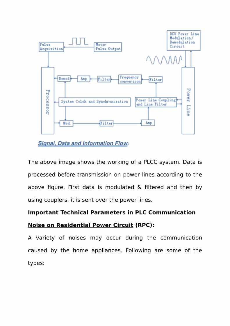
The above image shows the working of a PLCC system. Data is
processed before transmission on power lines according to the
above figure. First data is modulated & filtered and then by
using couplers, it is sent over the power lines.
Important Technical Parameters in PLC Communication
Noise on Residential Power Circuit (RPC):
A variety of noises may occur during the communication
caused by the home appliances. Following are some of the
types:

1. Noise synchronous to the power system frequency (50Hz
or 60 Hz) – This type of noise is generated because of different
kind of switching devices.
2. Noise with a smooth spectrum – The sources of such type
of noise are the appliances that are not operating
synchronously with the power line frequency. For example the
small motors with several windings can generate such type of
noise.
3. Single Event Impulse Noise – Switching of devices, that
contain a capacitor, generates such type of noise. The reason is
sudden discharge of the capacitor in the RPC.
4. Periodic Noise – The type of noise is generated by
fluorescent lights, television receivers etc.
These are some ways to reduce the noise in between the
communication over power lines:
a. Implementation of Forward Error Correction (FEC) codes
with interleaving can reduce the noise in category 1, 2 and 3.
b. Frequency Hopping with the FEC coding can be
implemented to deal with the unknown frequencies.

c. While modulating the signal on to the power lines,
television line frequencies should be avoided.
Signal to Noise Ratio:
Signal to Noise Ratio (SNR) is a measurement of quality of the
signal. It indicates the amount of the noise in a signal. SNR can
be formulated in the following way:
SNR = Received Power / Noise Power
Increasing SNR means increasing the performance of the
communication system. By applying noise filters on household
appliances, the noise entering into the power system can be
reduced. However it will increase the cost of the appliances but
is a better solution to improve overall performance.
Signal Attenuation:
Signal attenuation is basically the reduction in strength of the
signal. A signal attenuation of about 100dB/Km occurs for low
voltage power lines and 10dB/km for high voltage lines. It
creates a need of continuous repeaters over a fixed distance. A

number of factors that are responsible for signal attenuation
include distance, time, frequency of the signal, etc
PLCC SYSTEM: The frequency range over which PLCfrequencies are transmitted is usually 15 KHz to 500 KHz. Powerline itself is the medium for transmission of carrier frequenciesapart from transmission of those within the power frequencyrange. Since both the frequencies are transmittedsimultaneously over the same power line, some essentialoutdoor equipments are required to discriminate the said twofrequencies at the transmitting or receiving substation. Theseare line traps and coupling capacitors. A line trap also called a‘Wave Trap’, offers high impedance to carrier frequency (15 KHzto 500 KHz) current and thus prevents it from entering into thepower equipments in the switch yard. The high inductance ofthe line traps at high frequency itself accounts for this property,and hence, the line trap offers very low impedance to thepower frequency current. On the other hand, a couplingcapacitor because of its high capacitive reactance offers highimpedance to power frequency current and at the same timeoffers low impedance to carrier frequency current.
a> Channel Description : A PLC channel connectingtwo stations includes the following equipment at eitherend.
i> Indoor Carrier Terminal (Carrier Set)
ii> Signal path including co-axial cable
iii> Outdoor coupling equipment and tuner (linematching equipment between transmission line andthe co-axial cable).
The channels must be so planned that the signals areconfined to the desired path and unwanted signals areexcluded. As mentioned earlier these functions can beachieved through the use of line traps and couplingcapacitors.

The arrangement of outdoor coupling equipment is shown
in the following fig.
b> Methods of Coupling : Usually there are two typesof coupling
1 Phase to Ground Coupling and
2 Phase to Phase Coupling.
The arrangements are shown in the following figure.
1. Phase to Ground Coupling : Coupling to the power lineis effected between the conductor of one phase of thepower line and the earth. Earth return path is employed

for the communication circuit for communication betweentwo stations.
2. Phase to Phase Coupling :
Coupling to the power line is effected between the conductorof one phase and the conductor of another phase of thesame power line. The two phases may belong to the samecircuit or to different circuits of the same power line (InterCircuit Coupling).
Although for reasons of economy, phase to ground coupling isemployed between substation of less importance, phase tophase coupling is essentially recommended for all practicalpurposes for all power lines of 132 kV, 220 KV and 400 KVsystem with the idea that in the case of a broken conductor orsnapping of conductor, communication can still be carried outover the healthy phase conductor, though at a higherattenuation. Besides phase to phase coyupling has also got theadvantage of lower signal attenuation over phase to groundcoupling under normal condition. Thus phase to phase couplingis applicable not only for speech communication and expresschannels, but also for telemetering and teleprotection network,where reliability of operation is an important factor.
c> Channel Equipments :
i> Line Trap : As discussed earlier, the function of a line trapis to present a high
blocking impedance to the carrier frequency currents, whileintroducing negligible impedance to the power frequencycomponents. The carrier frequency characteristics of the linetrap are determined by the inductance of the trap and theimpedance it offers to carrier frequency components. Line trapsgenerally fall into two categories. One is the resonant or tunedtrap and the second is the Wide Band trap.
Resonant trap blocks only one or two components and havevery low inductance less than o.5mH (generally 0.2 mH). Wide

Band trap blocks the available carrier frequency rangecompletely or a larger portion thereof have typically inductanceup to 2mH (generally 1 mH).
Wave traps are generally rated for line operating current (powerfrequency) with permissible overload capacity. Wave traps aregenerally inserted in series with the power lines. However theIEC recommends a certain grading as to the rated currents andassociated short circuit resistance. Thus rated short durationcurrent related to theline trap refers to themaximum value of therms currents stated inKA, whose effect thewave trap will withstandfor a period of 1 second,following a continuousloading with ratedcurrent understandardizedtemperature condition. Besides the wave trap must be able towithstand the first current amplitude, which is 2.55 times therated short duration current.
For the purpose of blocking carrier frequency/ range of carrierfrequencies resonant tuning is done with tuning capacitor, alsocalled tuning pot. In some wave traps the tuning pot areaccommodated inside the cylindrical coil. Other designs providefor a housing protected against rain to be installed close to thetrap. A simplified diagram is shown for a wide band wave trap.
The requirements imposed on tuning capacitors are stringent.They must be deigned to withstand very high test voltages,because a high voltage drop occurs across the coil in the eventof short circuit currents and also travelling waves mightdamage the tuning capacitor. To replace the defective tuningcapacitor the power system must be inserted between theterminals of the coil of the line trap. The arc over voltage of

these surge arrestors, lies, on one hand below the voltage forwhich the tuning capacitors are rated and on the other hand,above the voltage produced across the coil in the event of ashort circuit current surge. The tuning capacitors are therebyprotected against the momentary over voltages entailed by thetravelling waves. Sustained over voltage for a short durationresulting from a short circuit current surge are not sufficientlyhigh to cause the arrestor to arc over. This eliminates thedanger of destruction of the arrestor. The station arrestorsmeant for the protection of the power lines and equipmentshave got a different characteristic from the surge arrestorassociated with the line traps. To prevent the small arrestors ofthe line trap from being destroyed by the arcing over of thestation arrestors, both type of surge arrestors must be designedfor the same surge current discharge capacity although theyare rated for greatly different arc over voltages. In case of itsreplacement afore said criteria must be given dueconsideration.
SERVICE CONDITIONS
. Operating Point: Outdoor
. Ambient Temperature: -40C to +45C
. Altitude: Not greater than 1000m
. Power Frequency: 50/60Hz
. Atmospheric Condition: Free of damaging gas or excessivedust.. Abnormal Condition: Above or below the specifiedtemperature range, salt, spray, industrialpollution, or other environmental factors which could seriouslyaffect the operating conditions
MOUNTING OPTIONS
a. Suspension line traps are provided with one, two, or foursuspension points and eyenut(s),which must be turned tightly during assembly to mount the linetrap in a vertical state. Generally these types are used for

voltages less or equal to 132KV, where size and weight of wavetrap is small.
b. For pedestal mounted line traps, aluminum pedestal(s)should be mounted to the lowerspider first, then connected to the post insulator. For large linetraps with three or foursupports, every support point shall be levelled to preventinsulators or line traps fromcarrying undue force. Generally these types are used forvoltages greater or equal to 220KV, where size and weight ofwave trap is quite large.
Application chart for line traps with a blocking impedence of800 Ohms. The blocking resistance is not less than 570 Ohmsfor wide-band traps, and is at least 800 Ohms for single-frequency traps. (Line Traps with other blocking impedances,such as 400, 600 or 1000 Ohms, are also available.)

Specification of wave traps used for 400KV, 220KV and132 KV outgoing or incoming lines
Voltage Class 400KV 220KV 132KV
RatedInductance(mH)
2mH 1mH 0.5mH
RatedContinuousCurrent(A)
2000A 1000A 630A
Rated short-time Current,r.m.s./Duration(KA/s)
63KA 40KA 25KA
AssymetricPeak Current(KA)
161KA 102KA 63.8KA
Power Loss 27.6KW 9.68KA 3.81KW
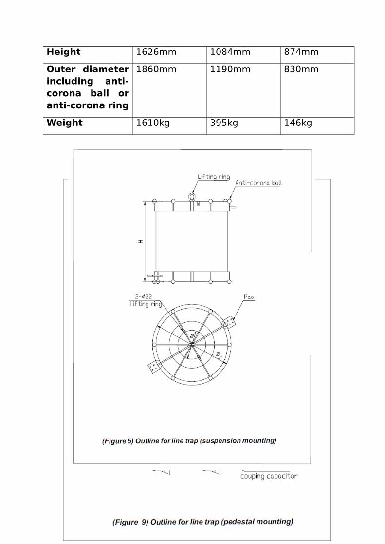
Height 1626mm 1084mm 874mm
Outer diameterincluding anti-corona ball oranti-corona ring
1860mm 1190mm 830mm
Weight 1610kg 395kg 146kg

ii> Coupling Capacitor & Capacitive VoltageTransformer (CVT) : As stated earlier, the coupling capacitorblocks the power frequency currents and at the same timeallow to pass the high frequency signals. For 66KV and 132 KVthe ratings of the coupling capacitors are normally 8800PF and5575PF respectively, whereas for 220 KV and 400 KV systemsthey are usually rated for 4400PF and 2200 PF respectively.Coupling capacitors are invariably connected at the end of theline i.e. ahead of the first disconnecting switch or line isolator atthe switchyard end so as to maintain voice/data communicationeven when the power line is disconnected by the line isolator.
iii> Line Matching Unit (L.M.U) : Transition from overheadline to power cable results in substantial mismatch loss acrossthe cable input,primarily due tothe mismatch ofcharacteristicimpedance of theoverheadtransmission lineand the highfrequency co-axial cable. Thecharacteristicimpedance (alsocalled the surgeimpedance) usually varies between 300 and 350 ohms for 132,220 and 400 KV depending upon the tower configuration andconductor spacing. The characteristic impedance of the highfrequency co-axial cable usually lies within the range of5oohms and 150 ohms. It is therefore necessary to arrange formatching equipment at the transition point. The equipment iscalled Line Matching Unit (L.M.U), which consists of a specialmatching circuit (mainly an impedance matching transformer)that is inserted between the power line/ equipment and thehigh frequency co-axial cable, thus minimizing to the extent

possible, the mismatch loss from the power line to thecommunication equipment. In case of phase to phase coupling,apart from installation of LMU on one phase another suchequipment called the Line Matching and DistributionUnit(LMDU) is installed on another phase with the same idea toavoid the mismatch loss. However the L.M.D.U consistingusually of a matching transformer of opposite polarity to that ofL.M.U serves to cancel out the noise in the line to a greatextent. L.M.U and L.M.D.U are interconnected through a HFcoaxial cable, but HF cable is finally drawn from the LMDUterminal upto the indoor PLC terminal and hence supports thedistributing function of L.M.D.U.
The schematic diagram of outdoor couplingarrangement is shown in the following figure
iv> Protective Device : A three-element protectivedevice is also an outdoor equipment comprising of 3 separateindependent small units mounted on C.C/C.V.T structure. Theprotective device is used to protect the communication systemfrom dangerous over voltages. It usually consists of
a. Drainage Coil

b. Surge arrestor &c. Earthing switch.
The charging current of the coupling capacitor increases withthe operating voltage and with the coupling capacitances. Thisis safely conducted to ground by the drainage coil. If the lineside of the coupling capacitor is interrupted, over voltage up tothe magnitude of the operating voltage may occur on theequipment side of the capacitor. Great stress is thereforeplaced on optimum reliability and a copper conductor of atleast¼” diameter is used in connection with 10KV support althoughthe conductor carries normally only a small current andtheoretically no voltage against the ground.The surge arrestor is rated for an arc over voltage of approx. 2KV and is provided to initiate in case of travelling waves or incase of an interruption of the ground conductor, immediategrounding at the point where over voltage occurs. Here also toprevent this arrestor from being destroyed by the stationarrestor arcing over, they are rated for greatly different arc overvoltages. Since the main purpose of this small surge arrestor isto protect the outdoor communication equipment, particularlythe L.M.U/L.M.D.U and its delicate components like the tuningcapacitor etc. the arc over voltage should be below the voltageratings of the said equipments. This insulation co-ordinationfeature should be taken care while replacing the tuningcapacitor or the L.A itself, particularly if the puncture of thecapacitor is caused by the high level switching surge orlightning surge at 400KV substation or power station.
A ground switch permits the entire outdoor circuit to begrounded behind the coupling capacitor without interruption ofthe transmission during maintenance of the outdoorcommunication equipment.
v> H.F Co-Axial Cable: The co-axial cable is of singlecentre conductor type. The wire serving for carrier energytransmission and the cable sheath as the return path. The HFco-axial cable is normally used for low impedance inter

connection between the outdoor L.M.U/L.M.D.U and the indoorcarrier terminal end. If both the shield ends are grounded, largesurge currents can flow under certain conditions and this cancause saturation of the impedance matching transformer of theL.M.U/L.M.D.U resulting in an inoperative carrier channel. A co-axial cable consists of a single copper conductor havingpolythene insulation, which is enclosed in copper shieldingbraid and in turn in a polyvinyl plastic jacket. The nominalcharacteristic impedance of the co-axial cable is 50/75/125ohms.
vi> Indoor Communication Equipment :
a. PLC Terminals (Carrier Sets) : For telephoneconversation only single purpose carrier terminals were first inuse, utilizing 300 to 2000 Hz for speech band. Carrier bandswere subsequently developed for simultaneous transmission ofspeech, telemetry and supervisory control signals for SCADA,utilizing (300-2000) Hz for speech and (2160 – 3400) Hz bandfor super imposed tele-signalling purpose. These entire bandslying within the AF range of frequencies having band width from0 to 4 KHz also called side band. Modulation of the carrier withthe A.F band results in two side bands in the carrier rangecovering the upper side band of 0 to 4 KHz and lower side bandfrom 0 to -4 KHz. The mode of transmission is based on“amplitude modulation” (AM) with “Single Side Band” (SSB)transmission. PLC terminals are usually suitable for operationon 48V D.C, with the positive terminal of the battery connectedto the solid earth.
b. Trunk Dialing System through EPAX : Recenttrend is to use digital EPAX for trunk dialing system. The EPAXusually serves as terminating exchange for carrier telephones.EPAX handles both local and long distance traffic on differenttrunk routes by enabling fully automatic operation among thelocal subscribers of the exchange and any outgoing direction ortrunk line over carrier channel. The EPAX is usually acombination of PAX of modular design along with modular cards

containing the features of FGS (Four wire Group Selector) fordirection discrimination of trunk PLCC routes, both the PAX andthe FGS being housed in the same cabinet, which is on floormounting type. The EPAX is suitable for operation on (-)48 V.D.C
c. Telemetering : The function includes telemeteringof measurements (e.g. Active power in MW, Reactive power inMVar, line currents in amp, Bus voltage in KV) and teleindicating of the position of different power switchingequipment e.g. circuit breakers etc from various remote powerstations/ sub stations to the data concentrator computer(Personal Computer) at the Central Load Dispatch Station forData acquisition and processing and thereby effectingsupervisory control of the power system network.
CARRIER AIDED DISTANCE PROTECTION
Protective relaying should be provided for all EHV transmissionlines to automatically disconnect the faulted line sectionswithin few milliseconds. For high speed protection, particularlyto ensure simultaneous operation of both the circuit breakers atthe two ends of the line, the most natural solution is to providecarrier aided protection so that inter tripping occurs almost atthe same instant on the other end on receipt of the transmittedtripping signal from the sending end. The distant relay beingcloser to the point of fault of the first zone will transmit thetripping signal and immediately a coded pulse train or certainsinusoidal frequencies in the AF band are sent out from theprotective coupler in the carrier set and transmitted over PLC tothe other end for decoding and reception in the AF band in thecounterpart protective coupler for inter tripping the circuitbreaker through operation of the associated relay. Thecontactor unit, which is a part of the protective coupler housedinside the carrier terminal, interfaces the protective couplerwith the relaying system at either end of the line. Transmissionof the said coded signal or the sinusoidal frequencies in the AF
band is however effected on simultaneous fulfillment of twoconditions.
i. Tripping command for direct tripping must be sensed. And
ii. Pilot frequency transmission should either be absent duringthe momentary period or should fall below the threshold level.
Exclusive PLC terminals with associated protection couplers areearmarked at both the ends for this purpose. In case of 400KVtransmission line, carrier protection involves two such exclusivePLC terminals with associated protection couplers at both endsof the line for the sake of reliability. In case of 220 KV andmostly in 132 KV power lines, permissive mode of tripping isalso employed, where in addition to the conditions mentionedabove, tripping command is transmitted only when it ispermitted by the starter relay on operation of the associatedrelay contact. In case of 400 KV system however the standardpractice is to employ both tripping features as well aspermissive tripping in the protective coupler for carrier aideddistance protection.
Auxiliary DC Power Supply SystemThe most critical component of a protection, control, andmonitoring system is the auxiliary dc control power system.Failure of the dc control power can render fault detectiondevices unable to detect faults, breakers unable to trip forfaults, local and remote indication to become inoperable, etc.

The auxiliary dc control power system consists of the battery,battery charger, distribution system, switching and protectivedevices, and any monitoring equipment. Proper sizing, design,and maintenance of the components that make up the auxiliarydc control system are required. Many references for stationarybattery system design address only a specific batterytechnology, making it difficult to compare different types ofbatteries for their overall suitability to substation application.Also, most references do not address the particularrequirements of the electrical substation environment and dutycycle. This paper provides an overall review of things toconsider in designing the auxiliary dc control power system foran electrical substation.
BATTERY AND BATTERY CHARGER:-
INTRODUCTION:-
BATTERY 220 V DC:-
The storage batteries are installed in special room. The battery room should have adequate ventilation and lighting. The floor and walls should be acid resistance tiles. The battery cells are placed on racks. The racksare placed on porcelain insulators. The D.C bus bars are flat copper sections or tubular copper sections. The connections aremade by soldering or brazing. The conductors are covered by grease or electrolyte resistance varnish. The positive leads are painted red and negative leads blue. Only acid-proof cables must be used upon D.C switchboard.

Without battery the relay will not operate and also C.B the D.C. supply is used for automatic control telemetering equipment, communication equipments, Interlocking equipment and emergency lighting system.
TYPES OF BATTERIES:-
TWO TYPES OF BATTERIES AT SOJA are:-
P.L.C.C
STATION BATTERY
SUBSTATION BATTERY:- (for 400 K.V two sets)
MAKE: - auto bat
CAP: - 250 A.H
VOLTAGE: - 220 V
NO. OF CELL: - 108*2
1.P.L.C.C:-

MAKE: - Standard
CAP: - 600 A.H
VOLTAGE: - 220 V
NO. OF CELL: - 25*2
Battery Set:- Battery is considered as the heart of sub-station.
Sub-station battery sets
220 V D.C
Single or double
110 V DC
Single or double
48 V DC
Single or double
Battery specifications:-
Generally.. Telecom DC source.. 48 V DC.
PLCC.. 1 extra cell to compensate cable drop
50 V-200 AH means Battery set is having 25 nos. of 2-Volts cellsthat can deliver..
20 Amps for 10 Hrs 20Ax10H=200 AH at 100% efficiency
Battery structure
Hard rubber container Positive terminal post. Lead peroxide Negative terminal post. Sponge lead Vent plug Float level indicator Inter-cell connector strips

Electrolyte… H2SO4
Chemical reaction:- Pb + PbO2 + H2SO4
Discharge Charge 2PbSO4 + H2O
Battery charger:-
MAIN PARTS:-
1. FLOAT CHARGER2. BOOST CHARGER
Functions of Float Charger:-
Converts 3-Ph AC into 48 V DC (Rectifier) Normally it delivers load & give trickle charging to battery
bank Works on ‘Auto’ or ‘Manual’ mode
In ‘Auto’ mode, o/p DC voltage is controlled by ECU card to
predefine value irrespective of amplitude of AC voltage.
In ‘Manual’ mode, o/p DC voltage to be controlled manually
by external controlFunctions of boost charger:-
Converts 3-Ph AC into 48 V DC (Rectifier) Normally it is made OFF Works on ‘CC’ or ‘CV’ mode.

In ‘CC’ mode, battery can be charged at constant
current. In ‘CV’ mode battery can be charged at constant
voltage.Need for boost charger:-
Boost charging is required only if whole battery bank is
drained considerably. At that time, Float charger will
deliver the load. Boost charger is made on when Float charger is out of
order. In this case, Boost section will charge the battery
bank and battery bank output from tap-cell will deliver
load.
Battery capacity can be calculated from the following
equations :-
1. Battery (kw)= Load KVA*Power-Factor/Inverter
Efficiency2. Number of Cells= Minimum allowable battery
voltage/Final voltage per cell3. Cells capacity(kw/per cell)= Battery kw/Number of
cellsCapacity of the Battery The capacity of a battery is expressed in ampere hour
(AH). The rating tells us about how much amount of current the
battery can supply for 1 hour. Capacity of a battery depends on
the following factors:

1. Rate of DischargeAH rating decreases with increase in rate of discharge. Due to
rapid rate of discharge cell potential falls significantly, due to
internal losses. Weakling of acid at higher discharge rate in
porous p[late is also greater at higher discharge rates. This also
affects the capacity adversely.2. Temperature:-
Capacity of a battery increases with increase in temperature.
(Include empirical correction formula)3. Density of Electrolyte
As the density of electrolyte affects the internal resistance and
the vigor of the chemical reaction, it has an important effect on
the capacity. Capacity increases with density.
Efficiency of the Battery
There are two different values of the battery efficiency:-
1. Ampere-Hour Efficiency2. Watt-Hour Efficiency
1.AH Efficiency:-

The ampere-hour efficiency is defined as the ratio of ampere
hour taken from battery to ampere hour supplied to it while
charging.
AH Efficiency=AH during discharge/ AH input while
charging
The typical value of AH efficiency is 90 to 95%. 5 to 10 %
reduction is due to losses taking place in the battery. The
ampere hour efficiency takes into account only the current and
time but it does not consider the battery terminal voltage.
2.Watt-Hour Efficiency:-
The Watt-Hour efficiency is defined as follows:-
WH-Efficiency= AH efficiency*Avg. cell voltage by discharging/
Avg. cell voltage while
charging
=70-80% usually
If the charging volts increase or decrease then WH-efficiency
will also decrease. High charging and discharging rates will
usually do this and hence are not recommended.

Maintain input AC voltage with specified band. Normally it
should be around 415 V AC +/- 10% /230 V AC +/- 10% Keep the batteries away from heat source, sparks etc. Charge the batteries once every six months, if stored for
long periods After a discharge recharge the batteries immediately Note down module voltage readings once every month. Charge the batteries only at 13.5 V per module. Do not add water or acid Do not attempt to dismantle the battery Do not boost charge the batteries for more than 12 hours Do not mix the batteries of different capacities of makes
SUB-STATION AND SWITCHYARD SUPPORT FACILITIES
Illumination and Lighting:
The Concessionaire shall design, provide & maintain at all timesa
good lighting & illumination system in a substation both for normal and emergency situations and to facilitate operation and maintenance activities and ensure safety of the working personnel.
Lighting Systems: The illumination & lighting systems shall comprise of the following:

AC Normal Lighting: AC lights shall be connected to Main Light Distribution Boards.
AC Emergency Lighting: Emergency lighting system with about 50% points connected to auto tart generators shall be available in Control room building, Fire fighting pump house, DG Set building & Switchyard. The emergency lighting system shall be kept normally ‘ON’.
D.C. Emergency Lighting: Strategically located lights in places like, Staircases, Corridors, Fire control Rooms, Battery Room, DG Set building and Control Room building shall be connected to DC emergency lighting system. These lights shall be kept normally 'OFF' and will be switched 'ON' automatically on AC failure.
Portable Lighting Fixtures: At least three (3) number battery powered portable lighting fixtures hall be kept at easily accessible points in the Control room building and one (1) each in DG Set Building and Fire fighting pump house.
Illumination Levels: Average illumination levels shall be as per CBIP manual on Substation. Adequate lighting is necessary for safety of working personnel and O&M activities
Recommended value of Illumination level
Control & Relay panel area - 350 Lux (at floor level) Test laboratory - 300 Lux Battery room - 100 Lux Other indoor area - 150 Lux Switchyard - 50 Lux (main equipment)
20 Lux (balance Area / road @ ground level)
Air Conditioning System:
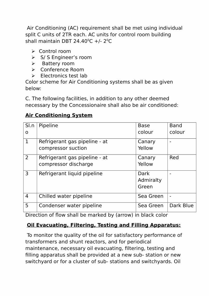
Air Conditioning (AC) requirement shall be met using individualsplit C units of 2TR each. AC units for control room building shall maintain DBT 24.400C +/- 20C
Control room S/ S Engineer’s room Battery room Conference Room Electronics test lab
Color scheme for Air Conditioning systems shall be as given below:
C. The following facilities, in addition to any other deemed necessary by the Concessionaire shall also be air conditioned:
Air Conditioning System
Sl.no
Pipeline Base colour
Band colour
1 Refrigerant gas pipeline - at compressor suction
Canary Yellow
-
2 Refrigerant gas pipeline - at compressor discharge
Canary Yellow
Red
3 Refrigerant liquid pipeline Dark Admiralty Green
-
4 Chilled water pipeline Sea Green -
5 Condenser water pipeline Sea Green Dark Blue
Direction of flow shall be marked by (arrow) in black color
Oil Evacuating, Filtering, Testing and Filling Apparatus:
To monitor the quality of the oil for satisfactory performance of transformers and shunt reactors, and for periodical maintenance, necessary oil evacuating, filtering, testing and filling apparatus shall be provided at a new sub- station or new switchyard or for a cluster of sub- stations and switchyards. Oil

tanks of adequate capacities for storage of pure and impure transformer oil shall be provided.
SF6 Filling, Evacuation, Filtering, Drying & Recycling Plant:
SF6 filling, evacuation, filtering, drying and recycling plant withadequate storage capacity shall be provided at a new sub-station or new switchyard or for a cluster of sub-stations andswitchyards along with trolley for filling or evacuation of SF6circuit breaker or gas insulated switchgear (in case of GISinstallation) and to monitor the purity, moisture content,decomposition product etc. of SF6 gas.
Fire Safety IssuesFIRE-FIGHTING SYSTEM
Fire and outbursts of oil filled equipment like power transformers, reactors, are not uncommon in electrical substations. Fire causes extensive damage to the equipment, civil works, control and protection cabling. The objective of modern fire extinguishing system is to extinguish the fire very quickly and to prevent spreading of fire. The fire fighting system should be automatic and adequate. The system is designed such that the fires are sensed by the detectors and the water-sprays in that zone are immediately actuated. The high velocity water spray is followed by sprinkling of water for along duration (about 30 minutes)
FIRE PROTECTION SYSTEM :
Emulsifier system for transformers and reactors Hydrant system for transformers, reactors and buildings. Fire extinguishers Fire alarm system Fire bucket
EMULSIFIER SYSTEM:
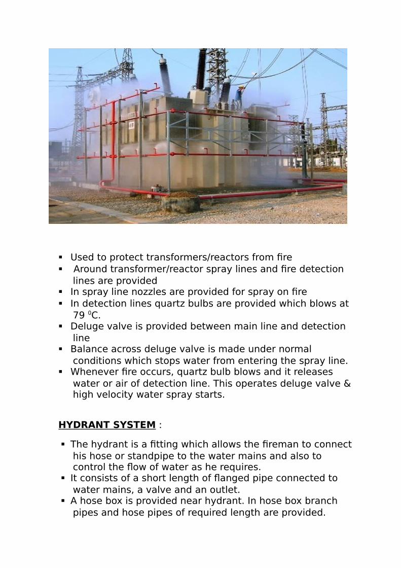
Used to protect transformers/reactors from fire Around transformer/reactor spray lines and fire detection
lines are provided In spray line nozzles are provided for spray on fire In detection lines quartz bulbs are provided which blows at
79 0C. Deluge valve is provided between main line and detection
line Balance across deluge valve is made under normal
conditions which stops water from entering the spray line. Whenever fire occurs, quartz bulb blows and it releases
water or air of detection line. This operates deluge valve &high velocity water spray starts.
HYDRANT SYSTEM :
The hydrant is a fitting which allows the fireman to connecthis hose or standpipe to the water mains and also to control the flow of water as he requires.
It consists of a short length of flanged pipe connected to water mains, a valve and an outlet.
A hose box is provided near hydrant. In hose box branch pipes and hose pipes of required length are provided.

Whenever fire occurs branch pipes and hose pipes are taken out and connected to the hydrant. The valve is opened to extinguish the fire.
FIRE FIGHTING PUMP HOUSE :
In the fire fighting pump house building following system is provided to maintain pressurized water system in the pipeline for hydrant spray and high velocity water spray system.
Diesel engine HVW motor (3 phase, 400/440V) Jockey pump(1 running, 1 standby) Pressure switches Air vessel Strainers
PRESSURE IN FIRE FIGHTING PIPELINE :
Normal pressure maintained in fire fighting pipeline is 8.0 kg/cm2 .
Whenever pressure reduces to 6.0 kg/cm2 the reduced pressure is sensed by the pressure switch which starts the jockey pump and after 8.0 kg/cm2 is achieved it stops automatically.
Generally 2 jockey pumps are provided. One of these acts as standby.
When fire occurs and hydrant/HVW system operates pressure in the pipeline goes below 4.5 kg/cm2, electric motor operates and build pressure to keep pressurized water supply continous. Motor is stopped manually after use of water for extinguishing fire.
If any problem with electric motor developes pressure in pipeline reduces to 3.5 kg/cm2 and the diesel engine startsto make up the supply of water.
Pressure switches are very important as the entire operation depends on them.
Strainers are provided to strain foreign materials from water.

FIRE EXTINGUISHERS :
Fire extinguishers are portable fire extinguishing equipments placed in fire prone areas to extinguish small fires that can develop into big fires and bring about huge damages. They have different types of medium for different knds of fire.
TYPES DESCRIPTION
Water type extinguisher
Contains water and CO2 cartridge. Before operation nozzle blockage is necessary to be checked
Foam extinguisher AlSO4 and NaHCO3 mixture makes CO2 and foam which extinguishes fire.
Dry powder extinguisher
Uses NaHCO3 or KHCO3 powder in combination with gas cartridges, for extinguishing fire.
CO2 type extinguisher
CO2 gas under pressurized conditions is used for extinguishing fire.

USES :
CLASS OF FIRE
FIRE PRONE MATERIALS FIRE EXTINGUISHERS USED
Class A Solids like paper Water, foam type
Class B Liquids like petrol Dry powder, CO2, Foam type
Class C Gases like methane, propane
Dry powder, CO2 type
Class D Metals like sodium Metal powder type
Electrical fire CO2 type
FIRE ALARM DETECTORS :
The fire alarm system comprises fire-detectors of the following types :
Fixed temperature heat detector Ionization smoke detector Break glass push button detector for indoor and outdoor
use.WORKING PROCEDURE:
Fixed temperature detectors are distributed throughout thebuildings and are connected in parallel with the manual push buttons for fire alarms.
The substation buildings( control room building, switchgearbuilding, stores etc.) are divided into several fire alarm zones. A fire alarm control panel is installed in the control room. The control panel indicates
1) General fires2) Faults

3) Alarms for water spray control panel In case of fire, the optical indication is obtained on
corresponding alarm zone in the fire alarm control panel and also a buzzer is sounded inside the fire alarm control panel.
The fire-horns are sounded in respective zone. The ac supply is switched off area-wise by respective
relays and contactors. The 11 KV auxiliary ac switchgear, low voltage ac
switchgear battery room and low voltage dc switchgear are provided with fixed temperature heat detector and response indicators.
The response indicators sound an alarm and provide indication on the fire alarm on the fire control panel located in the control room.
FIRE BUCKET
A fire sand bucket or fire bucket is a steel bucket filled with sand which is used to put out fires. Typically, fire buckets are painted bright red and have the word 'Fire' stencilled on them in white lettering. They are placed in prominent positions in rooms or corridors. They are a low-technology method of fighting small fires. The main advantages of fire buckets are that they are cheap, reliable and easy to use. The fire buckets are usually made round bottom so that they cannot be used for other purposes. Fire buckets are hung on fire bucket stands.

Sometimes used as a suppressant for class D fires. The sand must be completely dry or the intense heat of the burning metal will quickly flash the moisture into steam, splattering the burning metal on surrounding material and the operator.
Sand cannot reliably be used to extinguish burning magnesium, sodium, lithium, or other strongly reducing metals. These metals have the ability to strip oxygen from the sand, resulting in an even more intense fire
PRECAUTIONS AGAINST STARTING OF FIRE :
All personnel must become familiar with the safety rules and becareful to avoid fires. The rules recommended by the insurance companies, loss prevention board etc are followed for :
1) Design of substation2) Storage of equipment for erection3) Portable fire fighting sets and fire hydrant locations4) Removal of rubbish, packing wood.5) Special care, strict watch and ward to ensure no
smoking, no warning up fires, no loose connections of cables etc.
6) Training of personnel and rehersals7) No storage of inflammables in general stores.
PROTECTION AGAINST SPREADING OF FIRE :

FIRE WALL
In case of fire the transformer may outburst, causing damage to other substation equipments. The transformer oil may spread everywhere causing the spreading of fire in the cable trenches. Besides emulsifier protection, the power transformers in the outdoor yard are provided with barrier walls. The dimension of these walls should be such that the HT bushings are covered. The spreading of fire from one transformer to another is prevented by the wall. The walls are covered with refractory bricks.
OIL SUMP FOR TRANSFORMERS AND REACTORS :
The transformers are placed on specially designed foundations.An oil sump is provided in the switchyard at a lower level than the transformer foundation. The oil from the transformer foundation cavity flows into the sump through a well designed trench having good gradient with tile finish. The sump is underground. In the event of fire in the transformer, the oil fromthe transformer is drained quickly into the underground sump and the spreading of fire in the switchyard is prevented.