an architectural approach to software evolution …
TRANSCRIPT

Mälardalen University Licentiate Thesis
No.13
AN ARCHITECTURAL APPROACH TO SOFTWARE EVOLUTION AND INTEGRATION
Rikard Land 2003
Department of Computer Science and Engineering
Mälardalen University

Copyright © Rikard Land, 2003
ISBN number: 91-88834-09-3
Printed by Arkitektkopia, Västerås, Sweden
Distribution: Mälardalen University Press
ABSTRACT As time passes, software systems need to be maintained, modified, and integrated with other
systems so as not to age and become obsolete. In the present thesis, we investigate how the
concepts of software components and software architecture can be used to facilitate software
evolution and integration. Based on three case studies, we argue that considering a software
system at a high abstraction level, as a set of connected components, makes possible a cost
efficient and structured evolution and integration process. The systems in two of our case
studies are information systems developed in-house used for managing and manipulating
business-critical data. The third case study concerns an integration framework in which
systems can be integrated without modification.
In the thesis, we describe how several architectural alternatives can be developed based on
architectural descriptions of existing systems, and how these can be evaluated regarding a
number of concerns in a relatively rapid way, while achieving an acceptable confidence/effort
ratio. We describe how some of these concerns can be addressed in more detail, namely
maintainability, cost of implementation, and time of implementation; we also discuss the risk
involved in the decision. We show how although the existing architecture may reflect
insufficient design decisions and an outdated state of practice, it can and should be seen as a
prototype revealing strengths that should be preserved and weaknesses that should be
addressed during redesign. We also describe four different integration approaches and the
feasibility of each under various circumstances: Enterprise Application Integration (EAI),
interoperability through import and export facilities, integration at data level, and integration
at source code level. The two last of these are compared in more detail, revealing that code
level integration is more risky but not necessarily more costly than data level integration, but
is advantageous from a technical perspective.
Page i

ACKNOWLEDGEMENTS I want to thank my advisor Ivica Crnkovic for all help and support during the work with the
present thesis. I also wish to thank Compfab and Westinghouse for the case study
opportunities, and the Department of Computer Science and Engineering in Västerås, Sweden
and the Faculty of Electrical Engineering and Computing in Zagreb, Croatia for providing
good working environments.
Zagreb and Västerås 2003
Page ii

LIST OF PUBLISHED ARTICLES The following peer-reviewed papers have been published at various international conferences
and workshops, and are presented in reverse order of publication date.
Papers Included In the Thesis
The following papers are included in the present thesis.
Software Integration and Architectural Analysis – A Case Study
Rikard Land, Ivica Crnkovic, Proceedings of International Conference on
Software Maintenance (ICSM), September 2003.
Integration of Software Systems – Process Challenges
Rikard Land, Ivica Crnkovic, Christina Wallin, Proceedings of Euromicro
Conference, September 2003.
Applying the IEEE 1471-2000 Recommended Practice to a Software
Integration Project
Rikard Land, Proceedings of International Conference on Software Engineering
Research and Practice (SERP’03), Las Vegas, Nevada, June 2003.
Improving Quality Attributes of a Complex System Through Architectural
Analysis – A Case Study
Rikard Land, Proceedings of 9th IEEE Conference and Workshops on
Engineering of Computer-Based Systems (ECBS), Lund, Sweden, April 2002.
Information Organizer – A Comprehensive View on Reuse
Erik Gyllenswärd, Mladen Kap, Rikard Land, 4th International Conference on
Enterprise Information Systems (ICEIS), Ciudad Real, Spain, April 2002.
Page iii

Papers Not Included In the Thesis
The author has also authored or co-authored the following papers:
Taking Global Software Development from Industry to University and Back
Again
Igor Čavrak, Rikard Land, Proceedings of ICSE 2003 International Workshop on
Global Software Development (GSD 2003), Portland, Oregon, May 2003.
Is Software Engineering Training Enough for Software Engineers?
Ivica Crnkovic, Rikard Land, Andreas Sjögren, Proceedings of 16th International
Conference on Software Engineering Education and Training (CSEE&T),
Madrid, Spain, March 2003.
Software Deterioration And Maintainability – A Model Proposal
Rikard Land, Proceedings of Second Conference on Software Engineering
Research and Practise in Sweden (SERPS), Blekinge Institute of Technology
Research Report 2002:10, Karlskrona, Sweden, October 2002.
Page iv
TABLE OF CONTENTS
1. INTRODUCTION.........................................................................................................1
1.1 Hypothesis and Research Questions ............................................................................2
1.2 Methodology................................................................................................................5
1.3 Contribution .................................................................................................................7
2. TECHNOLOGY STATE OF THE ART ..................................................................14
2.1 What Is a Component?...............................................................................................14
2.2 Software Architecture ................................................................................................18
2.3 Architectural Documentation.....................................................................................24
2.4 Architecture Description Languages .........................................................................28
2.5 Architectural Analysis ...............................................................................................34
2.6 Architectural Styles and Patterns...............................................................................38
2.7 Technology Summary................................................................................................42
3. SOFTWARE EVOLUTION.......................................................................................44
3.1 The Evolution of Evolution .......................................................................................44
3.2 Maintainability...........................................................................................................49
3.3 Software Systems Integration ....................................................................................53
3.4 Evolution in Practice..................................................................................................54
3.5 Software Evolution Summary....................................................................................55
4. SYSTEM REDESIGN CASE STUDY ......................................................................57
4.1 Introduction................................................................................................................58
4.2 The Architectural Description ...................................................................................59
4.3 The Analysis of the Architectures .............................................................................66
4.4 General Observations and Lessons Learned..............................................................71
4.5 Conclusion .................................................................................................................74
5. INTEGRATION FRAMEWORK CASE STUDY ...................................................76
Page v

5.1 Introduction................................................................................................................77
5.2 The Model and the Framework..................................................................................78
5.3 Application Patterns – One Way of Reuse ................................................................86
5.4 Discussion ..................................................................................................................89
5.5 Summary ....................................................................................................................91
6. SYSTEMS INTEGRATION CASE STUDY ............................................................93
6.1 Introduction................................................................................................................95
6.2 Introducing the Case Study........................................................................................96
6.3 Integration Approaches..............................................................................................97
6.4 Development of Integration Alternatives ................................................................101
6.5 Related Work ...........................................................................................................111
6.6 Conclusions..............................................................................................................113
7. PROCESS CHALLENGES IN INTEGRATION PROJECT...............................116
7.1 Introduction..............................................................................................................117
7.2 Case Study ...............................................................................................................117
7.3 Analysis....................................................................................................................123
7.4 Summary ..................................................................................................................126
8. APPLYING IEEE 1471-2000 TO INTEGRATION PROJECT...........................127
8.1 Introduction..............................................................................................................128
8.2 The Case Study ........................................................................................................129
8.3 Measurable Benefits ................................................................................................134
8.4 Related Work ...........................................................................................................135
8.5 Conclusion ...............................................................................................................137
9. DISCUSSION AND CONCLUSION.......................................................................139
9.1 Assumptions and Limitations ..................................................................................139
9.2 Research Questions Revisited..................................................................................142
Page vi

9.3 Lessons Learned.......................................................................................................153
9.4 Related Work ...........................................................................................................154
9.5 Future Work .............................................................................................................156
10. SUMMARY................................................................................................................158
11. REFERENCES ..........................................................................................................160
12. INDEX........................................................................................................................182
Page vii

TABLE OF FIGURES Figure 1. Two views of the same simple system.....................................................................27
Figure 2. Elements of an Acme description. ...........................................................................31
Figure 3. An Acme description of a small architecture. .........................................................31
Figure 4. Process interaction when a simulation is started. ....................................................62
Figure 5. The different approaches for file handling. .............................................................64
Figure 6. The four alternatives. ...............................................................................................64
Figure 7. The processes in a small PAM system according to design A1 and A2..................65
Figure 8. The processes in a small PAM system according to design B1 and B2. .................65
Figure 9. The number of large data transfers across the network in five different scenarios. 67
Figure 10. The number of processes in running systems of different sizes. ...........................68
Figure 11: The relationships between the concepts. ...............................................................79
Figure 12: An issue with its aspects, relations, and views. .....................................................83
Figure 13. Today’s three systems............................................................................................97
Figure 14: Expected relations between risk, cost, and time to delivery................................101
Figure 15. The two main integration alternatives. ................................................................103
Figure 16: The outlined project plans. ..................................................................................109
Figure 17: The estimated cost and time to delivery. .............................................................111
Figure 18. Today’s three systems..........................................................................................118
Figure 19. Project phases. .....................................................................................................120
Figure 20. The two main integration alternatives. ................................................................122
Figure 21. Project phases . ....................................................................................................129
Page viii
1. INTRODUCTION Many ways of improving the understandability of large programs have been suggested, and
throughout the years some generally adopted concepts have crystallized – “modularity”,
“information hiding” and “separation of concerns” are some of these. The ultimate concern is
to develop and evolve high-quality systems in a cost-efficient manner. More recently, the two
complementary research fields of component-based software (focusing on the problem of
writing reusable software entities – components) and software architecture1 (dealing with the
structural arrangement of components) have appeared to accomplish the same thing.
While academic research in software architecture has so far mainly focused on the design of
systems before they are built, the architectural documentation being used during
implementation, the component community has focused more on the use of components in
evolving systems. With the present thesis, we contribute, by means of a survey of the relevant
literature, three case studies and a discussion, to the overall research in architecture and
components, addressing issues not thoroughly investigated to date. We focus on software
evolution (i.e. all software in use is changed gradually as time passes) rather than new
development, and in particular software integration (ranging from collaboration to
amalgamation of several existing systems to constitute a new system). Another of our goals is
to make architectural analysis rapid rather than exhaustive, relying more on intuition and
experience than on comprehensive analysis using existing techniques (such as formal
methods).
We have formulated a general research hypothesis and four more specific research questions,
listed in section 1.1 below. We have provided answers to these through three case studies: a
system redesign case study [103] reprinted in chapter 4, an integration framework case study
1 In the present thesis, the term “architecture” and its derivates (“architectural” etc.) will be used
interchangeably for “software architecture”.
Page 1

[62] reprinted in chapter 5, and a systems integration case study [105-107] reprinted in
chapters 6, 7, and 8. These chapters are reprints of previously published conference papers.
The remainder of chapter 1 defines the research objectives in more detail, describes the
methodology used and summarizes the contribution of the thesis. Chapters 2 and 3 survey
approaches to the concepts of components, software architecture, and software evolution in
literature with emphasis on issues related to the present thesis. Chapters 4 through 8 present
our case studies. Chapter 9 uses the literature survey to generalize our findings from the case
studies and discusses their limitations. This is followed by a brief summary in chapter 10.
1.1 Hypothesis and Research Questions
The main hypothesis underlying the present thesis is that conceptually separating software
into components [42], and reasoning about the relationships between these components – the
system’s architecture [13] – are useful means to manage software evolution in large complex
software systems in a cost efficient manner.
Although architectural analysis and system decomposition into components as well as
composition of components are well known research subjects and relatively widespread in
practice, there is still much to do to improve the state of practice, not least concerning system
evolution and integration. So far, architectural evaluation [34] has mostly been used during
development of new systems. We use architectural analysis to validate the hypothesis. Such
analysis often includes abstracting or improving the system’s documentation to include
architectural documentation (see e.g. [35]) by decomposing the existing software into
components. Through case study opportunities we have been able to investigate how far the
hypothesis holds in practice. We will present the major issues we have investigated to support
(or contradict) the hypothesis, in the form of four questions (“Q1” through “Q4”, where “Q”
stands for “question”).
Page 2 Chapter 1: Introduction
One evolution scenario is when a part of a system has to be redesigned, not to include more
functionality but to improve its extra-functional qualities2. To what extent can such a system
be redesigned without massive rewrite by considering it as a connected set of components? In
this scenario, it makes sense to put some effort into evaluating several alternative designs
beforehand and estimate their properties – not least their associated future maintainability. To
which extent does it make sense to describe and analyze the system at the architectural level,
as a set of software components, in this context? Can such analysis reveal weaknesses of
design alternatives, to enable a well-founded decision on which alternative to choose? Let us
call these issues on system redesign “Q1”.
Another increasingly important aspect of software evolution is system integration. Many
organizations have a large amount of technically separate systems, although conceptually
related, and the reasons and situations in which software integration occurs are many. The
software may have been acquired from several sources, which explains why it is not
integrated although interoperability would be beneficial. But even with software developed
in-house, there may be a need for integration as separate systems evolve and grow into each
other’s domains. When two companies merge the result may be that the merged company
owns overlapping systems. The systems may be tools used only within a company to run its
core business, or it may be the products the company manufactures. How can the concepts of
architecture and components be used when integrating complex software systems? How can
these concepts be used when developing a general integration framework? How can these
concepts be used when developing a customized, tight integration? How can architectural
2 With “extra-functional” , we intend features that are not mere “functionality”, many of which are
relatively intangible and escape quantification, such as performance, maintainability, availability,
usability or reliability. These are also commonly called “non-functional” properties, “quality”
attributes, or more popularly “ilities” (since many of these features are have the suffix “ility”).
Depending on the context, we may use any of these terms in the present thesis.
Page 3

analysis help in developing a long-term integration strategy? Let us call these integration
issues “Q2”.
When analyzing an architecture before building a system, one wants to assess that it will
provide the required functionality as well as having acceptable performance, being
maintainable, and have many other “extra-functional” qualities. But all of these are of minor
importance if not the business goals can be met, e.g. if the system will be too costly or take
too long to build. Also, even if two different architectural alternatives are similar in these
respects, one might be considered less risky due to e.g. a possibility of reusing existing code
or not requiring total long-term commitment. How can such organizational and business
concerns be addressed by architectural analyses and decisions during system evolution? Let
us call these organizational and business issues “Q3”.
When developing a new system, one has a large set of technologies, architectures, etc. to
choose from. When evolving or integrating existing systems, these possibilities seem to be
restricted due to the technologies and architectures used in the existing systems. More
specifically, which are these restrictions? Are there possibilities and opportunities as well?
Let us call these issues “Q4”.
Let us summarize these research questions:
How can the concepts of architecture and components be beneficially used to
estimate a software system’s properties during its evolution? (Q1)
Is it possible to beneficially use the concepts of architecture and components
when integrating existing software systems, and how can this be done? (Q2)
How are architectural analyses and decisions related to organizational and
business goals during system evolution? (Q3)
How does the architecture of an existing system restrict or facilitate its
evolution? (Q4)
Page 4 Chapter 1: Introduction
In using the term “beneficially”, we have two specific notions in mind: avoiding software
deterioration and achieving cost-efficiency, described presently.
• Even if a system is initially built to be maintainable and modifiable, the typical
observation is that as it evolves, it deteriorates, meaning that it becomes more and more
difficult to understand and maintain – which often negatively affects extra-functional
properties such as performance and robustness before long. One important long-term goal
when maintaining or modifying a system is not only to implement the requested changes,
but also to do it in such a manner that the system does not deteriorate. How can the
concepts provided by research in software architecture and component-based software be
used to achieve this goal?
• The term “beneficially” should also be understood in the context of cost-efficiency: we
are not interested in what can be done, if the resources required are too great to justify the
expenditure. People and organizations are typically reluctant to try new technologies and
processes, and prefer small-scale, low-cost experimenting first; especially as the effort
required increases dramatically as the architectural alternatives to be analyzed as well as
the features to analyze increase in number. We have therefore chosen to focus on
situations in which the software is to evolve using limited resources.
1.2 Methodology
When research is begun in a particular field, the problem itself is not always obvious.
Experience reports and case studies are the usual means of gaining insight into the problem,
and outlining possible solutions. When many case studies demonstrate consensus regarding
certain issues, the research is maturing, and experiments should be conducted to identify
variables affecting the outcome, and to establish relationships between these. The fields of
software evolution, software components, and software architecture have left their infancy but
while some issues have been clarified, there is still much to explore. The research presented in
this thesis falls into the relatively early exploration category, not being completely novel but
still only outlining the problem itself. Gathering data from experience reports and case studies
Page 5
in combination with studies of similar cases is therefore appropriate, and this is the
methodology we have chosen.
When conducting this kind of research, one must be aware of the limitations of this approach.
First, unwanted and even unknown factors, which cannot be avoided, affect the outcome. It is
practically impossible to carry out the same project “in parallel” with “equivalent” people
etc., so the researcher must consider why some factors affected the result more than others.
Second, in case studies, the research hypothesis may have to evolve as the projects they study
evolve – real projects are dynamic and must adjust to changing circumstances out of the
control of the researcher, who cannot be sure exactly what type of observations to expect.
Third, the research objective may be in conflict with business considerations if the
economical conditions change. But case studies have certain advantages, which makes the
methodology suited for investigating the presented questions. They permit the study of real
industrial cases, complex and many-faceted as they are. This both enables the study of
hypotheses in an industrial setting, necessary to validate the usefulness in practice of any
research finding, and the identification of open issues. This provides the researcher with an
understanding of a problem in a more holistic way, which forms an indispensable informal
basis for argumentation and elaboration – even though this “understanding” is hard to
quantify.
The author has been a participant in three industrial projects, serving as case studies or
experience reports, in two of the case studies as an active member, and in one, as a discussion
partner. To avoid the observations being subjective, other people have been involved, and the
observations were then generalized by means of literature studies and discussions with
academics. The three projects have resulted in five published papers, and the review process
used at scientific conferences ensures a certain degree of confidence in the scientific
soundness of the analyses.
Page 6 Chapter 1: Introduction

1.3 Contribution
The present thesis contributes to a wider understanding of the nature of software evolution by
introducing the notions of architecture and components. Our specific case studies contribute
to the general understanding of the problem and are shown to support the hypothesis that the
architectural approach to software evolution is beneficial, with the problem of software
deterioration in mind and particularly addressing cost-efficiency.
The case studies have been described in five published papers, which are reprinted in full as
chapters 4 through 8. The only changes made to the original publications are the following:
• All references have been collected in chapter 11 of the thesis.
• The layout has been modified to adhere to that of the rest of the thesis, including e.g. the
positioning of figures and capitalization of headings. The numbering of headings and
references (and the format of references) has been updated to make these chapters an
integral part of the thesis.
• One incorrect figure text has been corrected (Figure 6).
The remainder of this section is divided into two parts: first, the contents and contribution of
each of the case studies are described, and second (page 10ff), the research questions are
revisited and answered.
System Redesign Case Study
This case study is based on the following paper (reprinted in chapter 4):
Improving Quality Attributes of a Complex System Through Architectural
Analysis – A Case Study [103]
Rikard Land, In Proceedings of 9th IEEE Conference on Engineering of
Computer-Based Systems (ECBS), Lund, Sweden, IEEE Computer Society, 2002.
The case study describes how a part of a software information system had proven unstable.
One system part consisting of a number of cooperating, distributed processes was difficult to
Page 7
debug and test, and during runtime, manual intervention was often required to shut down
erroneous processes. The case study describes a redesign approach including architectural
evaluation and analysis. Extra-functional attributes of the system part, such as performance
and maintainability, were evaluated to permit comparison between four different redesign
alternatives.
Integration Framework Case Study
This case study is based on the following paper (reprinted in chapter 5):
Information Organizer – A Comprehensive View on Reuse [62]
Erik Gyllenswärd, Mladen Kap, and Rikard Land, In Proceedings of 4th
International Conference on Enterprise Information Systems (ICEIS), Malaga,
Spain, 2002.
The second case study describes a framework for integration of information systems. The
framework builds on the idea of using existing systems as components in a larger, integrated
system. Different systems typically handle different aspects of the same data, and the
framework enables a uniform view of and access to the information residing in different
applications, presenting the users with a consistent view of the data. The framework basically
assumes nothing from the existing applications. With relatively little effort, the framework
can be implemented in an organization and its existing systems integrated. To enable a tighter
integration, as perceived by the users, more effort may be expended, for example in
modifying or wrapping the existing systems, or short-cutting their database access.
This case study also discusses how a small company was able to build the framework with
few resources thanks to extensive reuse of existing products and technologies (which can be
seen as a form of integration).
Systems Integration Case Study
Different types of observations on the third case study were made in the following papers
(reprinted in chapters 6 through 8):
Page 8 Chapter 1: Introduction
Software Integration and Architectural Analysis – A Case Study [106]
Rikard Land, Ivica Crnkovic, Proceedings of International Conference on
Software Maintenance (ICSM), IEEE Computer Society, 2003.
Integration of Software Systems – Process Challenges [107]
Rikard Land, Ivica Crnkovic, Christina Wallin, Proceedings of Euromicro
Conference, 2003.
Applying the IEEE 1471-2000 Recommended Practice to a Software
Integration Project [105]
Rikard Land, Proceedings of International Conference on Software Engineering
Research and Practice (SERP'03), CSREA Press, 2003.
In this case study, three systems that had been developed and used mainly in-house, were,
after a company merger, found to have overlapping functionality and were identified as being
suitable for integration. The three papers/chapters contain different types of observations of
how a decision regarding an integration approach was reached. The first describes how four
different integration approaches were discussed and how two of these (sharing data only, or
integrating the source code) were more thoroughly evaluated and compared at the
architectural level. This included analyzing how the architectural alternatives addressed a
large number of stakeholder concerns. The second describes the process used in integrating
the software systems and identifies certain challenges to this process. The third describes how
a very lightweight analysis was used, relying heavily on the developers’ intuition (based on
experience), using the IEEE standard 1471-2000’s focus on stakeholders’ concerns [76].
Since these chapters were originally published separately as conference papers there is a
certain amount of overlap and duplication of the text and figures introducing the case study;
the focus and conclusions differ however between the chapters. Our apologies to the readers
for this inconvenience.
Page 9

Our research questions were addressed in the papers as described in the following.
Q1: How can the concepts of architecture and components be beneficially used to
assess a software system’s properties during its evolution?
This question was mainly investigated in the system redesign case study, as presented in
chapter 4 and the systems integration case study as presented in chapter 6. When evolving a
system, as well as when developing a new system, the most suitable of several alternative
directions is that to be chosen. These two case studies show both how such alternatives can be
developed on the basis of architectural descriptions of the existing systems, and how these can
be evaluated and compared using limited resources. It is possible to apply a lightweight
analysis on the architectural level to some properties, to be able to evaluate a larger number of
stakeholder concerns and spend more time on the more important and/or uncertain properties
of the system. We also analyze (in chapter 8) how the introduction of the IEEE standard
1471-2000 [76] was introduced into a systems integration project with measurable benefits at
little cost.
There are also a number of characteristics of redesign and integration activities not present in
new developments. First, the requirements are already there, at least to a considerable degree.
Second, the existing implementation can provide invaluable information about good and less
good design alternatives. Based on this knowledge, many of the components of the previous
system(s) will be preserved, some will be changed somewhat, some will be totally removed,
and some added. Some structural features may be preserved, while those considered
insufficient are modified.
Q2: Is it possible to beneficially use the concepts of architecture and components
when integrating existing software systems, and how can this be done?
Research question Q2 was investigated from two different points of view: from that of a
framework manufacturer and from that of those performing an internal integration after a
company merger.
Page 10 Chapter 1: Introduction

First, integration of legacy applications into a framework was investigated in the integration
framework case study, which is presented in chapter 5. It shows that it is possible to integrate
existing systems without modifying them. The framework presents an opportunity to integrate
systems even when source code is not available; all that needs to be known is some type of
API, even if only in the form of command line arguments. To begin with, the user interfaces
of the original systems are used, and the integration is on the data level. With more effort and
information, it is possible to shortcut the database access and present a homogeneous user
interface to the users.
Second, in the systems integration case study [105,107], as presented in chapters 6, 7, and 8,
we describe an enterprise which, after a company merger, had three information systems with
overlapping functionality. The systems were developed in-house and used mostly internally
for the company core business, but were also installed on the premises of several customers.
We describe how an architectural approach can be used to construct and evaluate different
integration alternatives. This involves investigating the architectures of the existing systems
and creating similar architectural descriptions, the components of which can then be
reconfigured. It is shown that by using the IEEE standard 1471-2000 [76], it is possible to
evaluate many concerns of several alternatives during a short time. We also describe the
possibilities and implications of different integration alternatives; in particular we compare a
data level integration with a full, code level integration.
Q3: How are architectural analyses and decisions related to organizational and
business goals during system evolution?
This question is addressed mainly by the systems integration case study (chapters 6 through
8), where cost, time to delivery, and risk of implementation were the most decisive factors
when choosing between two architectural alternatives for software integration. When building
a new system, it is possible to estimate the effort required to build each component based on
their respective estimated complexity, size, and similar. When integrating existing systems,
these estimations of effort required must also take into account issues such as reuse, rewrite,
Page 11
and new code. This will give a measure of the total implementation cost of the new system.
To estimate the time of implementation, the dependencies between the activities involved and
any possibility of executing them in parallel must be identified. This can be done on the basis
of architectural descriptions of the systems to be built. When the resources available for
implementation are not known beforehand, it is not possible to specify dates of deliveries, but
an activity diagram can be prepared showing the required activities with their associated
efforts and the dependencies between them.
The need to evaluate risk only became apparent at the end of the case study project, when
management was to make its decision. This need had not been addressed and remains an
important open issue for future study, how can the risk associated with different architectural
alternatives be evaluated?
Q4: How does the architecture of an existing system restrict or facilitate its
evolution?
This question is addressed by all three case studies, i.e. chapters 4 through 8. The evolution
and integration of existing software are restricted by the technologies used in its development,
and integration becomes additionally problematic due to the different technologies and
languages used in different parts of the existing systems, bridged using customized solutions.
If the changed requirements include improving extra-functional properties the existing
architecture, as described by its architectural patterns, may be insufficient. And during
integration, systems with different characteristics, including different architectures, must be
merged. The databases used in information systems may be commercial or proprietary, and
may range from relational databases to object-oriented databases to only a file structure. The
data models in the systems are very likely different, even though they model the same
business data. Under these circumstances, any integration attempt will be costly.
But while an existing architecture certainly restricts system evolution, it can also be utilized
to facilitate evolution. In the system redesign case study (chapter 4) the existing architecture,
although insufficient for the new requirements, could be used to demonstrate which concepts
Page 12 Chapter 1: Introduction

worked well and which did not. In the systems integration case study (chapters 6 through 8)
the three systems to be integrated represented three different architectural approaches, and it
should be no surprise that the most modern architecture was considered to be technically
preferable and was the obvious choice of the developers (although it was, for other reasons,
discarded by the managers). The integration framework (chapter 5) provides certain
integration possibilities if the systems to be integrated have certain architectural features:
what type of database they use, what type of API they provide, in which environment they run
(mainframe, PC, Unix, etc.).
Page 13

2. TECHNOLOGY STATE OF THE ART In this chapter, we take a look at the existing practice and research we build our work upon.
We start by discussing what a component is, and continue with the structure of component
assemblies – a system’s architecture. We will present definitions of architecture and discuss
their implications, we will describe the somewhat different views of architecture in academia
and in industry, present architectural documentation good practices, including the notion of
architectural views and viewpoints (or viewtypes), Architecture Description Languages
(ADLs), architectural analysis, and architectural styles and patterns.
But let us start with discussing what a software component really is – or rather, depending on
whom you ask: what a component can be.
2.1 What Is a Component?
To be able to sort out how the term “component” is used in the present thesis it is necessary to
present some uses of the term, and which of these we have adopted. In their introduction to an
SEI technical report on Component-Based Software Engineering, Bachman et al discuss
highlight the diverse uses of the “component” term by stating that “all software systems
comprise components” and that the “phrase component-based system has about as much
inherent meaning as ‘part-based whole’” [10]. However, they continue by discriminating
components resulting from top-down design decomposition from components already
available for composition. That is, the process of building a system from readily available
components differs in many ways from the process of designing a system from scratch. Many
large companies have moved from building complete hardware/software systems to acquiring
standard hardware, and later also software such as operating systems [41], and the top-down
approach to system development is no longer feasible. In the case studies of the present thesis,
we mainly use components resulting from decomposition.
Let us anyhow discuss the idea of using available components when assembling systems.
Components available in the market place are often called “off-the-shelf” (OTS) or
Page 14 Chapter 2: Technology State of the Art

“commercial-off-the-shelf” (COTS) components. The expected benefits are that it is possible
to build systems faster and cheaper while preserving or even increasing the quality of the
system as compared to building the whole system in-house [43,66,179]. At the same time, the
possibilities are restricted since one can only choose from available components. Some claim
that that a component presents 90% [142] of the desired functionality, and the developing
organization then has to decide whether the additional 10% can justify a much higher cost and
delayed release date. The market for commercial software components has increased during
the nineties [191] but currently seem to decrease. Still, component-based development may
occur in-house, e.g. through adopting a product line approach [33] (see also page 55f).
To make component-based development possible, there must be frameworks and
environments describing the rules for composition as well as runtime support. For source
code components, the framework is the programming language. With the emergence of
component models such as CORBA [175], COM [23], Java 2 Enterprise Edition [131,153],
and .NET [180] it has become possible to manufacture and use components as binaries (See
e.g. [47] for a comparison of these). In this way, components become language-independent
and may be used from any language or development environment supporting the component
model. For example, one popular framework for composing graphical components is the
language Visual Basic – or rather the product Visual Basic, which provides a user-friendly
integrated development environment – but the components may be written in other languages
as long as they are compiled and packaged as COM or .NET components.
Szyperski captures the notion of “component” described so far is in a commonly cited
definition [179]:
A software component is a unit of composition with contractually specified interfaces
and explicit context dependencies only. A software component can be deployed
independently and is subject to composition by third party.
Page 15
To enable a clear separation between components, which is required when they are deployed
independently and composed by third party, the interface becomes crucial. A component user
should not be required to understand how a component works, only how to use it. A
component thus has to specify how it can be used, and this interface description is used as a
contract between the component and the component user – it would make no sense to call it in
any other way than what its interface specifies. This notion of interface as described in an
interface definition language usually includes method signatures (method names, return types,
and parameter names and types), but nothing more. It has been notified that this is not
enough, since the accompanying documentation of the semantics of these methods may be
incomplete or wrong. For example: the component’s requirements on the environment, its
behavior in case of failure, and its performance under different circumstances are not
specified; neither is the actual semantics of the methods specified. One typically has to rely
on documentation in natural language and code examples. Current research on component
interfaces includes formal semantic specifications [121], through contracts [135]. Garlan et al
describe a case where the chosen components made different assumptions about their
environment, assumptions were undocumented and so subtle that this was discovered the hard
way, during integration, quadrupling the project’s time and schedule. The authors named this
problem “architectural mismatch” [57]. Johnson writes that if “components make different
assumptions [about its environment] then it is hard to use them together” [83].
With independent deployment, it has become possible to upgrade components without re-
installing the whole application. In this way, error corrections or performance improvements
in a single component can easily be deployed into already installed systems. However, if the
syntax or semantics of the call interface of the component is different from the previous
version, applications using this component will likely fail, and in particular when several
applications use the same component the problem easily becomes unmanageable – the “DLL
hell”. These issues require structured approaches similar to classical configuration
Page 16 Chapter 2: Technology State of the Art

management [109], and Microsoft’s .NET [180] addresses many issues that were problematic
with its predecessor COM [23].
Let us now turn to the notion of component as a unit of decomposition rather than of
composition. To be able to understand and manage a complex software system, it makes sense
to separate related pieces of functionality into separate components. The requirements may be
logically structured in a way that makes separation of functionality into components
straightforward. Or internal functions identified to be similar may be separated into methods
or components, possibly parameterized; for example, there may be library routines for sorting
and converting internal data types. But there are other reasons as well for componentizing a
system, of more organizational kinds. For example, clearly defined components enable
distribution and even outsourcing of development efforts [120].
How can these two approaches, composition and decomposition, be integrated? It is
obviously a challenge to combine the process of decomposing a system into manageable
pieces and that of assembling useful components into a system. It is naïve to believe that the
parts of a top-down decomposed system will be readily available. Development using
components has to include iterations between architectural design to know approximately
what components are needed and component search, evaluation, and selection [78]. In many
cases, the use of certain types of components such as operating systems and databases is more
or less required initially, due to the enormous effort involved in developing this functionality.
For other types of components, there is a gray zone: if a component does not provide all the
required functionality or is unstable, the same effort saved by acquiring rather than
developing a piece of functionality may be spent on working around flaws and adding the
missing functionality in an awkward way.
Whether we think of source code or binary components, and independent of whether our
approach to software development is top-down decomposition or bottom-up composition,
components are not used in isolation. The components interact and form a structure, which to
Page 17

a certain extent determines the system’s properties. This structure is usually called the
system’s architecture.
2.2 Software Architecture
Today’s notion of software architecture goes back to the early seventies, manifested by e.g.
Dijkstra’s description of the “THE” system [48], Parnas’ “Criteria To Be Used in
Decomposing Systems into Modules” [144] and Brooks mentioning a system’s “architecture”
[27]. Information hiding and similar ideas paved the path for object-orientation, and later
binary software components. The large-scale structure itself was given attention during the
first half of the nineties, when the importance of software architecture was recognized and
gained momentum [2,46,59,148,173]. During this time, Rapide was developed, possibly the
first architectural language [117]. Kruchten identified the need of describing the structure of
software from several different points of view [98]. There was a special issue on Software
Architecture in the IEEE Transactions on Software Engineering journal [75] and books began
to be published [28,174].
This increasing academic interest reflects what happened in the software industry at the same
time. Systems grew and became larger and larger. Object-orientation became popular and the
need for object-oriented analysis and design methods was addressed by e.g. the Booch,
Objectory, and OMT methods [18,77,155]. Recent trends include Internet technologies and
web applications typically implemented with a three-tiered architecture using .NET [180] or
J2EE [131,153].
In the following, we will look at how software architecture “serves as an important
communication, reasoning, analysis, and growth tool for systems” [12]. This includes issues
such as how to notate an architecture in text or using a graphical representation, informal and
formal analysis methods, architecture’s role in a life cycle context, and more. But let us first
try and understand what software architecture really is.
Page 18 Chapter 2: Technology State of the Art

Definitions
There is an abundance of definitions of software architecture around. The Software
Engineering Institute (SEI) maintains a list of definitions [164], but we will not repeat them
all. We will content ourselves with quoting two of the arguably most cited and well known
and discuss their implications. The arguably most commonly quoted definition was given by
Bass et al [13]:
The software architecture of a program or computing system is the structure or
structures of the system, which comprise software elements, the externally visible
properties of those elements, and the relationships among them.
To be correct, the most commonly quoted definition is that of the first edition of the book,
which reads “components” instead of “elements” [12]. This change reflects that architecture
does not only deal with “components” in the compositional sense described in the previous
section.
We can note several implications of this definition. First, a system has not only one structure
but several, “superimposed one upon another” [27]. You can e.g. consider the source code
files and their dependencies as one structure, and the runtime processes and their interactions
another. This feature of architecture is captured by the concept of architectural views (see
section 2.3). Second, the properties of interest of the components are those that are externally
visible, which is its interface (in a broad sense). However, it is a great challenge, partly
addressed by the present thesis, to decide which properties that can indeed be ignored and
only need to be dealt with later. Third, every software system has an architecture according to
this definition, because you can always view a system as a set of related components,
however messy the structure you perceive the architecture to be.
There are many definitions on the same theme, describing structures of components. But let
us also consider the definition given by Perry and Wolf in 1992, which is of a somewhat
different kind but also commonly quoted [148]:
Page 19
Software Architecture = {Elements, Form, Rationale}
In context, this compressed formula expresses that elements refer to what is now usually
called components, form is structure, and rationale refers to “the motivation for the choice of
architectural style, the choice of elements, and the form”. This definition (and some more)
considers the rationale for choosing one solution or another part of the architecture itself,
while the definition by Bass et al only considers the structure, as objectively observable in a
system. This is not a mere academic difference, but have practical consequences. For
example, which is the most accurate architectural description: the box-and-line documentation
describing the basic design decisions or the code itself (or a diagram of interdependencies
extracted from code)? Is it possible to re-engineer a piece of software to find its architecture?
Carmichael et al “compare the extracted structure to that which was intended by the designers
of the system” and discuss the limited value of visualizing code structure if expecting to find
the intended design [30,157]. The difference between these definitions (and others) can be
explained by a slight difference in focus: from a development or maintenance point of view,
the fundamental design choices must be understood, but when working with technologies and
techniques, the reason to use a particular technology is not an issue for the technology itself.
These definitions thus reflect a difference in scope rather than ignorance or fundamentally
different opinions. We could even broaden the scope more: as described above, enterprise
architecture describes the structure of software in the context of an organization.
One thing that is not directly apparent from the definitions as presented here, but from the
context of these quotations, is that not only components (or elements), i.e. the boxes in a
graphical architecture description, are treated as first-class entities, but also connecting
elements or connectors (the lines). With “elements”, Perry and Wolf include “processing
elements”, “data elements”, and “connecting elements” [148], and with “structure” and
“relationships”, Bass et al include “connectors” [13].
Page 20 Chapter 2: Technology State of the Art

Software Architecture in Industry
The focus in texts by industry practitioners is not so much on the structure of the software
itself, or evaluation techniques, as on specific technologies on one hand and the business and
organizational context on the other. Significant for the industrial view is the focus is on the
architect as a person or a profession, rather than on the architecture as the structure of a
software system. It is people rather than technology, techniques, and processes that will
enable the building of large software systems [172]. The World-Wide Institute of Software
Architects (WWISA) is a nonprofit organization founded to “accelerate the establishment of
the profession of software architecture and to provide information and services to software
architects and their clients” [194]. In 2002 WWISA had “over 1,500 members in over 50
countries” [172]. One book in the “Software Architecture Series” co-sponsored by WWISA
[49,123,172] accordingly has the title “The Software Architect’s Profession” [172]. These
authors’ view of the profession, “the architect is the catalyst whose feet are planted firmly in
two worlds: the clients’ and the builders’”, reminds of Brooks’ [27]. This notion of
architecture denotes the structure of a system as perceived by the users [27] (or the
“inhabitants” [172]) rather than the internal structure.
Here it is also appropriate to briefly discuss approaches to “enterprise architectures”. There is
a correlation between the structure of an organization and that of its software. The “Zachman
Framework for Enterprise Architecture”, promoted by the Zachman Institute for Framework
Advancement (ZIFA) [198], is a framework within which a whole enterprise is modeled. This
is done in two dimensions: the first describing its data, its people, its functions, its network,
and more, and the other dimension specifying views of different detail [195,198]. Another
enterprise information systems framework is “The Open Group Architectural Framework”
(TOGAF) [139]. These frameworks thus in a way encompass more than the academic
definitions, in that e.g. people and business goals are included. At the same time, they include
less, in that the software modeled as part of the framework are software used for running an
enterprise. Software products such as e.g. process control or embedded software is not
Page 21

included, although these products also have architectures – i.e. when software architecture is
discussed as a technology, as the definitions above and the present thesis do.
The IEEE standard 1471-2000, “Recommended Practice for Architectural Description of
Software-Intensive Systems” [76], aimed at practitioners in industry, adopts the notion of
architecture being:
The fundamental organization of a system embodied in its components, their
relationships to each other, and to the environment, and the principles guiding its
design and evolution.
We can note several things from this definition. First, it reminds of the definition by Bass et al
[13] in that it talks about components and their relationships to each other and to the
environment. Second, it embraces the idea of the rationale behind design choices being part of
the architecture. Third, it is particularly aimed at being used in software system evolution.
The recommended practice contains a framework of concepts but does not mandate any
particular architecture description language or set of viewpoints to use. Rather, the emphasis
is on documenting the rationale for the choices made. Guidelines for how to make decisions
are also provided, and these are in essence very simple: every choice must address the
concerns of a stakeholder. These concepts are even defined in the standard, along with
definitions of “architecture” and “views”: a stakeholder is “an individual, team, or
organization (or classes thereof) with interests in, or concerns relative to, a system”, and a
concern are described as such:
Each stakeholder typically has interests in, or concerns relative to, that system.
Concerns are those interests which pertain to the system ’s development, its operation
or any other aspects that are critical or otherwise important to one or more
stakeholders. Concerns include system considerations such as performance, reliability,
security, distribution, and evolvability.
Page 22 Chapter 2: Technology State of the Art

This focus on addressing stakeholders’ concerns implies that nothing should be done that does
not address a real concern of a stakeholder, and this ensures that the efforts are concentrated
on the most productive activities.
Architecture in a Lifecycle Context
“Software architecture” is traditionally associated with the earliest design phase, occurring
before “detailed design”. But this has changed, and many sources now involve architecture in
more phases: “the role of the software architecture in all phases of software development is
more explicitly recognized. Whereas initially software architecture was primarily associated
with the architecture design phase, we now see that the software architecture is treated
explicitly during development, product derivation in product lines, at runtime, and during
system evolution. Software architecture as an artifact has been decoupled from a particular
lifecycle phase.” [21] According to IEEE 1471-2000, “architecting contributes to the
development, operation, and maintenance of a system from its initial concept until its
retirement from use. As such, architecting is best understood in a life cycle context, not
simply as a single activity at one point in that life cycle.” [76]. There are suggestions that
project management has much to gain from being “architecture-centric” [146], and reports
that during experimental prototyping and evolutionary development “explicit focus on
software architecture in these phases was an important key to success” [31]. The product and
the process affect each other, and the product’s architecture is the artifact that bridges the gap
between them. For example, resource planning cannot accurately be done unless there is an
architecture to base the work division on, but the scope of the product and resources available
are important when its architecture is being developed. One of the six “Industry-Proven Best
Practices” the Rational Unified Process (RUP) builds on is the use of component architectures
[99]. On the other hand, in agile methodologies such as eXtreme Programming (XP) [14,15]
the architecture is not designed or documented as such beforehand, due to the assumption that
requirements will change during development and the design will need to change accordingly.
Page 23

But architectural issues are included in the methodology: the code is to be constantly
refactored [54] to ensure the system always has a feasible architecture.
2.3 Architectural Documentation
Producing accurate documentation that is used in practice and continuously keeping it up to
date are always challenges in the software industry. Literature on architectural documentation
usually avoids these issues and instead focuses on good practices for architectural
documentation.
The uses of architectural documentation are many. First, an architectural description serves as
a communication tool between stakeholders of the system [13,35]. An architectural
description describes a system at a high level understandable by e.g. as managers, customers,
and users, as other artifacts such as source code or test cases are not. A system’s possibilities
– and limitations – can be explained to these stakeholders. Second, architectural descriptions
can be analyzed before a system is built [13,32,34,86,88,89]. This makes it possible to
compare several alternative architectures beforehand. Third, by describing several systems at
a high level, common patterns or styles are discernible. In this way, it becomes possible to
describe patterns [28,55,159] with known properties, which can be used when designing or
evolving other systems [34,76,174].
Considering the various existing graphical notations for capturing different aspects of
software systems, it seems as visual representations are intuitively appealing to humans.
Usually, the high-level structure of a software system is thought of as a box-and-line diagram.
But graphical descriptions of a system’s architecture tend to be ambiguous [13,34]. There
may be plenty of boxes and arrows, but it may be less clear what they mean exactly. Is a box a
design-time entity or a runtime entity? Not least the lines tend to be of many kinds. Does a
line represent a static or a dynamic relationship? What type of relationship – uses, sends
message to, inherits from, etc.? What does an arrowhead mean? Sometimes the difference
between two types of connectors is not obvious at first. One common example is the
difference between control flow and data flow; sometimes only one or the other occurs,
Page 24 Chapter 2: Technology State of the Art

sometimes they coincide, and sometimes they are directed at the opposite directions (e.g. an
asynchronous request for data). In architectural documentation, it is important to provide a
key to the graphical notation, or if possible use a standardized language [35] (such languages
are described in section 2.4).
It has also been repeatedly emphasized that the rationale for the choices made should be
documented [35,76]3. By understanding the choices made maintainers will arguably be able to
perform changes efficient and without violating the conceptual integrity of the system
[24,110]. Also, by documenting the assumptions for certain choices, it is possible to re-
evaluate the existing architecture as soon as these assumptions change.
Views
Other engineering products, such as integrated circuits, buildings, or cities are represented
differently depending on the purpose. For example, a city map4 may use different colors to
denote parks, buildings, and industry areas, but another map of the exactly same city contains
only straight colored lines with dots evenly spread. Each type of map is an abstraction of the
reality, emphasizing different aspects while ignoring others, designed to address different
needs: those of tourists or subway commuters. No abstractions reflect the full richness of
reality, and no single abstraction can therefore be used for all purposes. For a single piece of
software, it is obvious that its source code structure may differ completely from e.g. its
interaction patterns during runtime, and it makes sense to design, analyze, and document both.
With the words of Brooks: “As soon as we attempt to diagram software structure, we find it to
constitute not one, but several, general directed graphs, superimposed one upon another” [27].
In architectural documentation and design, this has given rise to concept of views, a term
3 As we saw earlier, some argue that rationale is indeed an integral part of an architecture. See page 20.
4 The most common analogy used for software architecture is that of building construction, which
some authors claim to be “perfect, profound” [172], while others find the metaphor “tired” [35].
Page 25
being defined by the IEEE 1471-2000 [76] as being a “representation of a whole system from
the perspective of a related set of concerns”.
Such views are typically visualized graphically as a box-and-lines drawing, with different
types of boxes and lines in different views. For example, in a runtime view of an object-
oriented system, we may have the component type “object” and the connector type “message”
to our disposal while a design-time view might include “classes” and “inheritance”. See
Figure 1. There are research on how to enable formal reasoning around how the components
of different views are correlated [67,196] (see also discussion on UML on page 32).
The language used can have a stronger or weaker syntax and semantics; it is not uncommon
in practice to not use an established notation but rely completely on intuition for
interpretation; it is also common to mix components and relationships that should belong to
different views, making the descriptions unnecessarily ambiguous. Such a description can be
useful for informal discussions or overviews of a system, but should not be documented for
the future – it will most surely be misunderstood and should not be seen as a substitution for
more detailed descriptions in separate views [35]. In Figure 1 we have adhered to UML
[19,183]; there is a class diagram to the left and a collaboration diagram to the right5.
A particular system is described in different views, but when discussing systems in general
the concepts of viewpoints [76] or viewtypes [35] can be used to denote a template from which
a view is instantiated, or a language in which the particular system is described – “a
viewpoint is to a view as a class is to an object” [76]. IEEE 1471-2000 defines “viewpoint” as
follows [76]:
5 What is usually called views in architectural terminology is called diagrams in UML.
Page 26 Chapter 2: Technology State of the Art

x:A y:A
b:B c:C
1.1
1.2
1.3.*
1.4
A
B C1..*
Figure 1. Two views of the same simple system.
A specification of the conventions for constructing and using a view. A pattern or
template from which to develop individual views by establishing the purposes and
audience for a view and the techniques for its creation and analysis.
This notion is not widely spread, and especially in early architectural literature the terms are
not separated, and in some contexts we would today rather use the terms viewpoint or
viewtype instead of view.
Various authors have suggested complementary views, the most known (and the earliest)
perhaps being Kruchten’s 4+1 views, where a logical view, a process view, a physical view,
and a development view are complemented and interconnected with a use case view [98].
Hofmeister et al suggest four similar views: a conceptual view, an execution view, a module
view, and a code view [71]. Buschmann et al list two different sets of four views, one
coinciding with the one given by Hofmeister et al and the other, now called “architectures”,
with Kruchten’s four views, not including the use case view [28]. Other authors have
suggested that four views are not sufficient and have described additional views perceived
useful in at least some cases, such as an architectonic viewpoint [122] and a build-time view
[181]. Recent approaches to views recognize the fact that “no fixed set of views is appropriate
Page 27
for every system” [35]. Clements et al provide broad guidelines and classify views in three
viewtypes [35]. IEEE 1471-2000 does not list any views other than to exemplify; instead it
specifies what is required of a view: it must document which stakeholders and which
concerns it addresses, and the rationale for choosing it [76].
2.4 Architecture Description Languages
As we have seen, architectures can be described roughly as a set of components connected by
connectors. Depending on the application domain and the view, the descriptions can contain
other entities as well. A number of formal languages have been developed to allow for formal
and unambiguous descriptions. Such an Architecture Description Language (ADL) usually
builds on a textual representation, which is easily visualized graphically (see e.g. Figure 3 on
page 31).
An ADL defines the basic elements to be used in an architectural description. Different ADLs
are designed to meet slightly different criteria, and have somewhat different underlying
concepts. An ADL specifies a well-defined syntax and some semantics, making it possible to
combine the elements into meaningful structures. The advantages of describing an
architecture using a formal ADL are several:
• Some formal analyses can be performed, such as checking whether an architectural
description is consistent and complete6.
• The architectural design can be unambiguously understood and communicated between
the participants of a software project.
6 Allen provides a good explanation of these notions: “Informally, consistency means that the
description makes sense; that different parts of the description do not contradict each other.
Completeness is the property that a description contains enough information to perform an analysis;
that the description does not omit details necessary to show a certain fact or to make a guarantee.
Thus, completeness is with respect to a particular analysis or property.” [7]
Page 28 Chapter 2: Technology State of the Art

• One may also hope for a means to bridge the gap between architectural design and
program code by transformation of a formal architectural description to a programming
language, or the opposite.
The rest of this chapter describes the basic characteristics of some ADLs briefly.
Rapide, UniCon, Aesop, Wright
The Rapide language [117], developed at Stanford University builds on the notion of partial
ordered sets. It is both an architecture description language and an executable programming
or simulation language. A number of supporting tools have been built, e.g. for performing
static analysis and for simulation.
UniCon [174], developed at Carnegie Mellon University, is “an architectural-description
language intended to aid designers in defining software architectures in terms of abstractions
that they find useful”. UniCon is designed to make “a smooth transition to code” [174],
through a very generous type mechanism: components and connectors can be of types that are
built-in in a programming language (e.g. function call), or be of more complex types, user-
defined as code templates, code generators or informal guidelines.
Aesop [56], also developed at Carnegie Mellon University, is addressing the problem of style
reuse. With Aesop, it is possible to define styles and use them when constructing an actual
system. Aesop provides a generic toolkit and communication infrastructure that users can
customize with architectural style descriptions and a set of tools that they would like to use
for architectural analysis. Tools that have been integrated with Aesop styles include: cycle
detectors, type consistency verifiers, formal communication protocol analyzers, C-code
generators, compilers, structured language editors, and rate-monotonic analysis tools.
Wright [7], also developed at Carnegie Mellon University, is a formal language including the
following elements: components with ports, connectors with roles, and glue to attach roles to
ports. Architectural styles can be formalized in the language with predicates, thus allowing
for static checks to determine the consistency and completeness of an architecture.
Page 29

ACME and ADML
Acme [58], developed by a team at Carnegie Mellon University, can be seen as a second-
generation ADL, in that its intention is to identify a kind of least common denominator for
ADLs. It is thus not designed to be a new or competing language, but rather to be an
interchange format between other languages and tools, and also allow for use of general tools.
One could devise one tool searching for illegal cycles, and use it for descriptions in any
ADLs, as long as there exist translation functionality between that ADL and Acme. Acme
defines 7 basic element types: components, connectors, systems, ports, roles, representations,
and rep-maps (representation maps). See Figure 2 for a description of the five most important
(figure slightly modified version from [58]). Acme’s textual representation of a small
architecture is found in Figure 3 (after [58]).
As was implied above, the success of Acme is highly dependent on the existence of tools and
translators. The research team at SEI behind Acme has constructed the graphical architectural
editor AcmeStudio. Translators between UniCon, Aesop, Wright, and Rapide have also been
constructed [58]. However, voices doubting Acmes universality can also be heard, stating that
“its growth into an all-encompassing mediating service never has taken place […] Acme
should probably be considered as a separate architecture description language altogether”
[45].
The Open Group found room for improvement of Acme and have defined the Architecture
Description Markup Language (ADML): “ADML adds to ACME a standardized
representation (parsable by ordinary XML parsers), the ability to define links to objects
outside the architecture (such as rationale, designs, components, etc.), straightforward ability
to interface with commercial repositories, and transparent extensibility” [141].
Page 30 Chapter 2: Technology State of the Art

Component Role Port
Connector
System
Figure 2. Elements of an Acme description.
System simple_cs = { Component client = { Port sendRequest } Component server = { Port receiveRequest } Connector rpc = { Roles {caller, callee} } Attachments : { client.sendRequest to rpc.caller ; server.receiveRequest to rpc.callee } }
Figure 3. An Acme description of a small architecture.
Industrial ADLs
As an example of an industrial ADL, let us briefly present Koala from Philips. Koala is a
component model and architecture description language used to develop consumer products
such as televisions, video recorders, CD and DVD players [188,189]. Koala deals with source
code components with not only “provides” interfaces (the ordinary API) but also explicit
“requires” interfaces (what the component requires from its environment), similar to input and
Page 31

output “ports” in Acme. While being an ADL used for modeling, Koala involves source code
generation and is also a runtime component model.
The Fundamental Modeling Concepts (FMC) [65,90,91] is “primarily a consistent and
coherent way to think and talk about dynamic systems” [65], but also comes with “a universal
notation originating from existing standards [which] is defined to visualize the structures and
to communicate in a coherent way” [65]. Its main focus is on human comprehension and
separates conceptual structures from implementation structures. It is based on theoretical
foundations such as Petri nets, and contains three distinct types of structures: compositional
structures, dynamic structures (behavior), and value structures (data). FMC can be seen as an
Architectural Description Language for describing the runtime view of a system. FMC has
successfully been applied to real-life systems in practice at SAP, Siemens, Alcatel and other
companies. It has also been used in a research project to examine, model, and document the
Apache web server [61,64].
We should also discuss UML (Unified Modeling Language), the current de facto-standard for
object-oriented design and modeling [19,71,183], but parts of it are also used for modeling
non-object-oriented software as well as for systems engineering. UML has adopted the notion
of modeling in several viewpoints, although in UML views are called “diagrams”; there are
class diagrams, object diagrams, statechart diagrams, sequence diagrams, deployment
diagrams, etc. In each diagram there are different components such as processes, nodes, etc.
Can UML be used for architectural modeling? Is UML an ADL? There are different answers
to this question, depending on whom you ask and what their criteria for an ADL are [36].
Some argue that since UML is de facto used in industry to model architectures, UML is an
ADL [93,97]. Others argue that UML lacks many features a fully-fledged ADL would have:
“UML lacks direct support for modeling and exploiting architectural styles, explicit software
connectors, and local and global architectural constraints” [124]. The confusion that may arise
from using the same notation for different levels of abstraction has also been pointed out [70].
UML is not primarily intended to be an ADL, and “if the primary purpose of a language is to
Page 32 Chapter 2: Technology State of the Art

provide a vehicle of expression that matches the intuitions and practices of users, then that
language should aspire to reflect those intentions and practices” [126]. UML can be extended
to incorporate ADL characteristics, for example by extending existing diagram types [156].
UML has also been subject to research on how architectural views can be correlated. There
are e.g. approaches to defining the semantic correlations between entities in different UML
diagrams [196] and to combine elements of different diagram types into more expressive
diagram types [67].
The big advantage of UML seems to be that it is widely used and understood, and depending
on the context, it may be a good or bad choice; Hofmeister et al chose UML to describe
software architectures, with the motivation that although “some of our architecture concepts
are not directly supported by existing UML elements […] the benefits to be gained by using a
standardized, well-understood notation outweigh the drawbacks” [71]. Medvidovic et al are
along the same line: “using UML has the benefits of leveraging mainstream tools, skills, and
processes” [124].
UML models are defined by meta models, which in turn are defined by meta-meta models.
The meta model level defines the language of models, i.e. meta models define legal UML
specifications (e.g. connections between classes). This architecture of the language allows
users to define new constructs. The idea of using the meta model level for extending UML
with architectural constructs has been investigated by Medvidovic et al [124], who also
investigated the possibility of constraining UML with its built in constraint language, OCL
(Object Constraint Language) [19]; this would enable existing UML tools to without
modification work with architectural models. Their conclusion was that, whichever strategy
chosen “adapting UML to address architectural concerns seems to require reasonable effort,
to be a useful complement to ADLs (and, potentially, their analysis tools), and to be a
practical step toward mainstream architectural modeling” [124].
The specification of UML 2.0 was recently officially adopted [140]. Some of the new
language features are of particular interest for the present thesis. “A first-class extension
Page 33

mechanism [which] allows modelers to add their own metaclasses” [140] could possibly
allow for architectural extensions in line with the suggestions of Medvidovic et al [124].
There is “built-in support for component-based development to ease modeling of applications
realized in Enterprise JavaBeans, CORBA components or COM+” [140]. There is also
“support for run-time architectures [which] allows modeling of object and data flow among
different parts of a system” [140]. How well UML 2.0 is received by the architectural
community, and to what extent UML 2.0 will be used in practice to model software
architecture remain to be seen.
Other ADLs
These were only examples of languages aspiring to be ADLs. There are numerous others with
more or less exotic names such as ArTek, C2, CODE, ControlH, Demeter, FR, Gestalt,
LILEAnna, MetaH, Modechart, RESOLVE, SADL, and Weaves; see e.g. [126,163,165] for
further references.
2.5 Architectural Analysis
Given an architectural description, it becomes possible to analyze it. The purpose of the
analysis may be e.g. to evaluate whether the design is good enough before implementing it, to
compare different alternative architectures, or to estimate the impact of a planned change to
an existing system. The approach to the analysis depends on its purpose; given a description
in a formal ADL it is possible to analyze it statically for consistency and completeness, it may
also be possible to execute or simulate it [6,7,117]. Another approach is to use stakeholder-
generated scenarios to analyze what happens in certain scenarios; extra-functional attributes
such as maintainability are typical candidates for this type of analysis. This section will
describe informal analysis methods.
Page 34 Chapter 2: Technology State of the Art
An important observation reported from case studies with informal analysis, apart from the
actual evaluation results, is the effect the analysis process has on people. These are explicitly
said to be both technical and social [12,88,89]. The analysis “acts as a catalyzing activity on
an organization”, in the meaning that “participants end up with a better understanding of the

architecture” and generates “deeper insights into the trade-offs that are implicit in the
architecture” [12], simply because the issue is brought to attention. The importance of letting
everybody involved influence th7e choices made is emphasized [12,19,20,88,89], which in
itself is an important step forward to create quality software.
None of these analysis methods are designed for any specific quality attributes or software
metrics, but rather to serve as a framework leading the analyst to focus on the right questions
at the right time. Any quality attribute can be analyzed with these methods; examples are
modifiability [88,102], cost [89,102], availability [89], and performance [87,102]. If anything,
SAAM is biased towards evaluating maintainability.
SAAM
The Software Architecture Analysis Method (SAAM) uses scenarios to evaluate quality
properties of an architecture [12,34,86]. Scenarios are developed by different stakeholders as
illustrations of likely or important possible future events affecting the system. These scenarios
are then “executed”, meaning that their impact on the system when they occur is assessed.
Different scenarios are used to estimate different properties; so can e.g. the scenario “the user
presses the ‘start’ button” address performance by tracing which components need to be
involved, how much database or network access etc. A scenario like “the commercial
database used is exchanged for a competitor” addresses maintainability: if many components
are affected, the database upgrade will likely be difficult and expensive.
SAAM cannot give any absolute measurements on quality properties, but should rather be
used to compare candidate architectures. The results are of the sort “system X is more
maintainable than system Y with respect to change scenarios A, B, and C, but less
maintainable with respect to scenarios D and E; X has higher performance in scenarios F but
lower in scenario G and H”. These results thus form a basis for project decisions where
priorities as short-term and long-term costs, time-to-market, and future reusability are
weighed against each other. To be able to compare architectures, they must be described in a
consistent and understandable way – thus some sort of ADL must form the basis of the
Page 35

analysis. For the outcome of the analysis to be reliable, it is crucial that the selected scenarios
are indeed representative for actual future scenarios. SAAM therefore emphasizes the
participation of all stakeholders of the system, i.e. project managers, users, developers etc.
A tool prototype for aiding in SAAM analysis (as well as aiding in documenting architecture
in general), “SAAMtool”, has been built [85].
ATAM
The Architecture Tradeoff Analysis Method (ATAM) also builds on scenarios generated by
stakeholders [34,89]. Here, the importance of making tradeoffs has been noticed, i.e. the
decision needed to choose between alternative architectures to arrive at a set of properties that
are acceptable. It is naïve to believe that architectural design aims at finding the architecture,
meaning the cheapest to build and the most resource-effective and the most portable and the
most reusable:
It is obvious that one cannot maximize all quality attributes. This is the case in any
engineering discipline. […] The strongest bridge is not the lightest, quickest to erect,
or cheapest. The fastest, best-handling car doesn’t carry large amounts of cargo and is
not fuel efficient. The best-tasting dessert is never the lowest in calories. [12]
Many such quality attributes are correlated to some extent with each other, meaning that
improving one often improves another – or deteriorates it. For example, optimizing
performance often makes the program less easy to understand and maintain. The engineering
approach is thus to try and find an acceptable tradeoff, considering not only the technical
aspects of the software, but include all related concerns such as management and financial
issues. ATAM supports projects when discussing the system and agreeing upon an acceptable
tradeoff by introducing the notion of tradeoff points:
Once the architectural sensitivity points have been determined, finding tradeoff points
is simply the identification of architectural elements to which multiple attributes are
sensitive. For example, the performance of a client-server architecture might be highly
Page 36 Chapter 2: Technology State of the Art

sensitive to the number of servers (performance increases, within some range, by
increasing the number of servers). The availability of that architecture might also vary
directly with the number of servers. However, the security of the system might vary
inversely with the number of servers (because the system contains more potential
points of attack). The number of servers, then, is a tradeoff point with respect to this
architecture. It is an element, potentially one of many, where architectural tradeoffs
will be made, consciously or unconsciously. [89]
The ATAM is somewhat more detailed than SAAM and defines nine steps. It requires
business drivers and quality attributes to be well specified in advance as well as detailed
architectural descriptions to be available. In some contexts, ATAM is a good choice, but in
other types of projects of more exploratory kind, it may be unfeasible.
ARID and QASAR
The Active Reviews for Intermediate Designs method (ARID) [34] builds on Active Design
Reviews (ADR) and incorporates the idea of scenarios from SAAM and ATAM. It is intended
to be a formal review procedure involving several stakeholders for evaluating partial
architectural descriptions. The quality attribute-oriented software architecture design method
(QASAR) puts architectural analysis and evaluation in an iterative development context [20].
According to this methodology, one should first design an architecture that fulfills the
functional requirements and then refine the architecture until the quality attributes are
satisfactory.
Clustering Techniques
We can also mention clustering techniques. Cluster analysis means grouping entities together
in clusters, based on a notion of similarity so that intra-cluster similarity or cohesion is high
and inter-cluster coupling is low. Clustering is used in as different areas as e.g. studies of
galaxies, chip design, economics, statistics, classification of species, and business area
analysis [118,193].
Page 37

In the software domain, coupling and cohesion are believed to impact extra-functional
attributes such as maintainability, flexibility, portability, and reusability [13]. By considering
a collection of software components a cluster at an appropriate level of abstraction, it is
therefore possible to reason about different properties of the particular division of components
into clusters. Clusters may be defined differently to achieve different goals. If clusters denote
source code modules, and procedures are considered components, it is possible to organize a
system so that procedures e.g. sharing resources are collected into cohesive modules [160]. If
clusters denote nodes in a network, it is possible to e.g. increase computing parallelism by
maximizing the cohesion inside a cluster and minimize the coupling between the clusters, i.e.
maximizing the number of connections between components within a single cluster and
minimize the number of inter-cluster component dependencies [130]. These approaches are
used to reorganize existing systems, where there are dependencies that were maybe not
anticipated in the design. They therefore serve as tools for evolution of an existing system
rather than during architectural design prior to system implementation.
One challenge when designing cluster algorithms is how to define what “similarity” means,
another is to decide whether one searches for the optimal solution or only one that is “good
enough” [160,193]. Yet another challenge is to find a level at which to try and find a suitable
solution: the most cohesive cluster is the one with all components inside it [193].
2.6 Architectural Styles and Patterns
As software systems have been built and used over the years, certain ways of solving
recurring problems have been repeatedly tried and proven to be “good”. Such solutions have
been generalized and made public in form of patterns or styles7, and given names such as
“model-view-controller”, “publisher-subscriber”, and “client-server”. We can note that there
are patterns for all levels of abstraction; Buschmann et al divide patterns into three levels:
7 The terms “pattern” and “style” are often used interchangeably; the present thesis will not distinguish
between these terms or elaborate upon possible differences.
Page 38 Chapter 2: Technology State of the Art

architectural patterns, design patterns, and code-level idioms [28]. Patterns are described
according to a three-part schema consisting of a problem within a context, and a solution
[28,55,159]. Attempts have been made to formalize what constitutes a pattern in a formal
language [2], but so far the great impact of patterns have been at the level of increasing the
knowledge of developers and architects.
There are several benefits of patterns. First, the solution is proven to be a good technical
solution for a certain type of problem. Instead of spending time inventing something, one can
immediately adopt a pattern that most likely is better than any new invention. Second,
patterns form a common vocabulary among developers, so other developers will immediately
grasp the basic idea when a system is said to conform to a certain pattern.
A style typically addresses specific problems, often quality-related:
When we have models of quality attributes that we believe in, we can annotate
architectural styles with their prototypical behavior with respect to quality attributes.
We can then talk about performance styles (such as priority-based preemptive
scheduling) or modifiability styles (such as layering) or reliability styles (such as
analytic redundancy) and then discuss the ways in which these styles can be
composed. [12]
Some styles found in literature are explained briefly below. We have listed styles discussed in
existing literature, even though it can be argued that some of these rather are e.g. lower-level
“techniques” (object-orientation) It may also be noted that some styles emphasize static
structure while others are useful to describe the dynamic behavior of a system.
With an object-oriented architecture, the focus is on the different items in the system,
modeled as objects, classes etc. Object-orientation as an architectural style is discussed in
literature [12,20,174], but it can be argued whether object-orientation is an architectural style
or belongs to lower levels of design.
Page 39

In a pipe-and-filter system the data flow in the system is in focus [12,35,173,174,190]. There
are a number of computational components, where output from one component forms the
input to the next. This style could be implemented e.g. as Unix processes and pipes, threads
with shared buffers, or a main function calling sub functions (filters) in a certain order (the
pipes are implemented as parameters to these functions). This is a suitable style when likely
maintenance tasks can be expressed as reconfigurations of filters; depending on the
implementation it may also be possible to allow users to reconfigure filters. This style fits a
program that can be expressed as analyzing and formatting text or data (for example,
compilers are often described as pipe-and-filter systems [4,174]), but does not express user
interaction or data storage.
A blackboard (or repository) architecture draws the attention to the data in the system
[12,173,174,190]. There is a central data store, the blackboard, and agents writing and
reading data. The agents may be implicitly invoked when data changes, or explicitly by some
sort of external action such as a user command. A database can easily be described by the
blackboard architectural style, where the blackboard itself of course is the data in the
database. Examples of agents are client applications, database triggers (small pieces of
program code that are executed automatically when data changes), and administration tools.
In a client-server architecture [12,20,171,173,174,190], the system is organized as a number
of clients issuing requests to a server, which acts and responds accordingly. Although client-
server is often thought of in terms of hardware, it is possible to implement a system
completely in software running locally organized as clients accessing a server. The rationale
of organizing processes in a system in this manner is that the server represents a resource that
can or must be utilized by several clients. In a hardware client-server system the resource is
typically file storage, a database, a printer, high computing power, or the ability of performing
a specific service (such as sending email). What further distinguishes the client-server style
from arbitrary communication is that clients are typically not aware of each other, can connect
Page 40 Chapter 2: Technology State of the Art
and disconnect dynamically, and all activities are initiated on request from a client, not the
server.
With a layered (or onion) architecture, focus is laid on the different abstraction levels in a
system, such as the software in a personal computer [12,20,173,174,190]. It is typically
visualized as a stack of boxes or a number of concentric circles. The layered style appears in
design time and reveals how source code modules depend on each other. The layers imply
how the modules, or layers if you want, are supposed to use each other, and the fundamental
interpretation is that any layer can use the layer underneath it, although there is room for
many variants [35]. By separating different levels of concerns, the layered style facilitates
maintenance. For example, a portability layer may be introduced at the bottom, abstracting
away the hardware and software platforms underneath it.
A close relative of the client-server style and the layered style is the n-tier architectural style
[13,35,170]. The tiers of this style are organized as a stack of components interacting in a
client-server manner. The n-tier style can also be confused with the layered style: both the
layered style and the n-tier style divide a piece of software into different logical parts that are
“ordered”. But while layers are foremost a design time artifact (and may be compiled into one
executable), tiers are easily discernible in runtime, as the different tiers typically execute on
different computers, and the connection between them are made in runtime (typically as
different types of network connections). The n-tier style is the common paradigm in
information systems, not least those based on the Internet. There is data and end user client
applications, and in a three-tier architecture there is a mediating component in between. The
computing, storage, and networking capacity can be individually adjusted at each tier to
maximize system performance; the system can also be adapted to take hardware limitations
into account such as low network bandwidth to the clients. Three-tier architectures are
believed to be maintainable, scalable, reusable, and reliable [170].
Software systems often control physical processes. There are a number of software paradigms
for process control [174,190]. The significant properties are that the software takes its input
Page 41

from sensors (such as a flow sensor), and perform control actions (such as closing a valve).
The control loop may be of feedback or feed-forward type.
Heterogeneous Architectural styles
Patterns or styles at the architectural level are more about concepts than about
implementation, and a very important use is to promote understanding and communication
among humans. For many systems it is therefore appropriate to describe them with several
styles simultaneously; such systems are called heterogeneous [12]. As with views, styles
abstract away certain elements and emphasize others. “The glasses you choose will determine
the style that you ‘see’” [35].
Bass et al identify three kinds of heterogeneity [12]:
• Locationally heterogeneous. Different runtime parts use different styles.
• Hierarchically heterogeneous. A system of one style can be seen as decomposed into
components, each of which may be structured according to another style.
• Simultaneously heterogeneous. Several styles serve as a description of the same system.
E.g. a multi-user database can be viewed as both a blackboard and a client-server
architecture. This heterogeneity “recognizes that styles do not partition software
architectures into nonoverlapping, clean categories” [12].
Some styles and patterns by their nature describe a system on a very high level, while other
styles may be applied on lower levels. For example, a three-tier system is likely to implement
at least the middle tier with a layered architecture, and an object-oriented language is
probably used. It is hard to conceive the opposite, a system that is described as layered on the
highest level, and where some layers are tiered – layers call each other locally while tiers are
distributed on several nodes.
2.7 Technology Summary
We have surveyed the literature to find a uniform description of what a component is. The
most common notion is that the term most often means a deliverable piece of executable
Page 42 Chapter 2: Technology State of the Art
(binary) software, manufactured out-of-house, or a runtime artifact (often the runtime instance
of a delivered binary component), but it can also be built in-house, and/or be the same as a
code module. We found that there is a great difference between components resulting from
top-down design decomposition and implementation-time composition.
We have studied the notion of software architecture, and discussed how to describe and
analyze it. This term concerns the structure of components, although one can discern a
change in wording to avoid confusion with the word component as described above. Instead,
the word entity can be used to generally denote a piece of software, be it discernible in
runtime or implementation time. The types of components/entities to choose depend on what
aspects of the system one want to see: runtime or implementation-time properties, and this
gives rise to the notion of architectural views. The architecture of a piece of software can be
described formally in an Architecture Description Language (ADL) , or less formal in e.g.
UML, which may be a good enough choice for many practical cases. We also noted that many
system architectures conform to well-known architectural styles or patterns such as the pipe-
and-filter and client-server styles, and described some of these. We presented two methods
for informal analysis of architectures: the Software Architecture Analysis Method, SAAM,
and the Architecture Tradeoff Analysis Method, ATAM.
Page 43

3. SOFTWARE EVOLUTION The present thesis is said to address software evolution with certain tools: reasoning in terms
of components and architecture. But what is software evolution? What is evolution? In
general, evolution is “progressive change” [114]. In the software domain, it may denote
several things. An executing program may modify itself automatically, if evolutionary
programming techniques such as genetic algorithms have been implemented [11,128]. The
process of evolving a specification into an executing program is also a type of evolution, but
this activity is usually called “development”, and the sub activities are named e.g. “design”,
“implementation”, “compilation”, “build” rather than “evolution”. But when considering the
development of a program at the level above, we find the most common use of the term
“evolution”, or at least the one we are concerned with in the present thesis: the process a
software system undergoes as it is continuously modified and released in new versions.
3.1 The Evolution of Evolution
This notion is not new. Perry refers to Brooks [26] and state that: “Evolution is one of
Brooks’ […] essential characteristics of software systems: the only systems that are not
evolving are the dead ones. Evolution is a basic fact of software life.” [147] Unless a system
is evolved it will age, meaning becoming less and less satisfying for the needs at hand. Parnas
establishes that “software aging can, and will occur in all successful products” [145]. In the
seventies, Lehman formulated his first “laws of software evolution” [113], which will be
returned to later in this chapter (page 46f). Closely connected to the concept of software
evolution is that of software deterioration, design erosion and similar [12,20,80,145,174,187].
As systems evolve, they become harder and harder to evolve further, and the original design
choices are violated in more and more places. In short, such systems’ complexity increases
unless work is done to reduce it. Software evolution, software deterioration, and software
aging are closely related: successful systems need to be evolved so as not to age, but while
being evolved they typically deteriorate. Approaches how to successfully evolve systems (to
Page 44 Chapter 3: Software Evolution

avoid them aging) therefore have to take software deterioration into account. We will return
to all of these notions throughout this chapter.
What and Why of Evolution
Lehman and Ramil have not only focused on “the how of software evolution” but “the what
and the why of evolution” [114]8. They describe a program classification scheme they name
SPE. In this classification scheme, software is divided into S-type, P-type, and E-type. S
stands for “specification”, but could also denote “static”, and includes programs that
“implement solutions to problems that can be completely and unambiguously specified, for
which, in theory at least, a program implementation can be proven correct […] with respect to
the specification.” E stands for “evolution”, and E-type software is defined as “a program that
mechanises a human or societal activity” [114] and includes all programs that “operate or
address a problem or activity in the real world”. Programs of type S do not evolve according
to the authors, since the requirements are stated formally and unambiguously, and they can be
made to fulfill their requirements once and for all, and be proven to do be correct. E-type
programs on the other hand “are intrinsically evolutionary” [114]; to remain satisfactory to
their users they must continuously evolve. It is meaningless to talk about the “correctness” of
E-type programs; they can only be more or less satisfactory in a certain context. They have to
evolve to stay competitive and used, since the context in which they execute evolve:
businesses evolve, societies evolve, laws and regulations evolve, the technical environment in
which the software executes and is used evolve, the users’ expectations of the software
evolve. These effects are partly due to numerous factors out of the software’s control, but they
8 Lehman and Ramil have worked with software evolution for decades. Instead of referencing the
original publications, we will use this reference throughout the section, since it summarizes much of
what they have done. Also, they have made some differences over the years and we reflect their most
recent statements.
Page 45

are also effects of the use of the software itself. P-type programs can take the properties of
both S-type and E-type programs and are not further discussed.
Lehman and Ramil also describe areas of software related evolution, and identify five
different “levels”. At the lowest level, we find what is usually called “development”, i.e.
progressive refinement from an initial vision via design and implementation to a released
program. At the second level, “a sequence of versions, releases or upgrades of a program or
software system” is discussed, the type of evolution mainly dealt with in the present thesis:
“changes in the purpose for which the software was acquired” makes the software deteriorate
in relation to its context, and the assumptions underlying the software are no longer valid. “In
short, software is evolved to maintain the validity of its embedded assumption set, its
behaviour under execution, the satisfaction of its stakeholders and its compatibility with the
world as it now is or as expected to be.” At the third level, applications, i.e. activities
supported by the software, evolve. This is partly because the software itself affects its
applications as new opportunities for enhancements and extensions are discovered, which
drives a never-ending need for further evolution. At the fourth level, the processes of software
evolution themselves have to evolve as research and practice finds new means of managing
software evolution, and as the software and its contexts evolves. Finally, at the fifth level,
models of software evolution, i.e. classification schemes such as is presented here, has to
evolve. “The process evolves. So must models of it.”
“Changes are generally incremental and small relative to the entity as a whole but exceptions
to this may occur.” [114] Our cases are such exceptions: redesign part of a system or systems
integration are relatively large changes.
Lehman’s Laws of Software Evolution
In 1974, Lehman formulated his first “laws of software evolution” for E-type systems [114].
They are based on observations of the evolution of the IBM OS/360 operating system, and
have later been revisited and supported by other observations; currently there are eight laws,
see Table 1.
Page 46 Chapter 3: Software Evolution

Table 1: Lehman’s laws of software evolution (after [114]).
Law No., Brief Name Formulation of Law
I. Continuing Change E-type systems must be continually adapted else they become
progressively less satisfactory.
II. Increasing Complexity As an E-type system evolves its complexity increases unless
work is done to maintain or reduce it.
III. Self Regulation Global E-type system evolution processes are self regulating.
IV. Conservation of
Organisational Stability
The average effective global activity rate in an evolving E-type
system tends to remain constant over product lifetime.
V. Conservation of
Familiarity
On average, the incremental growth tends to remain constant or
to decline.
VI. Continuing Growth The functional content of E-type systems must be continually
increased to maintain user satisfaction over their lifetime.
VII. Declining Quality The quality of E-type systems will appear to be declining
unless they are rigorously maintained and adapted to
operational environment changes.
VIII. Feedback System E-type evolution processes constitute multi-level, multi-loop,
multi-agent feedback systems and must be treated as such to
achieve significant improvement for other than the most
primitive processes.
Page 47

That is, E-type systems continually change, continually grow, become more and more
complex, and loose in quality unless conscious efforts are spent in reducing these effects. Any
evolution approach should try and mitigate the negative effects of these laws.
Software Deterioration
As said previously, E-type software has to evolve to avoid its being outdated, old-fashioned,
inferior to its competitors, etc. [145] But as it is evolved, the typical observation is that it
deteriorates or degrades [12,20,80,145,174], an effect sometimes called “design erosion”
[187]. Each change is done under time pressure, and the maintainer short-cuts some original
design decisions for one reason or another: they are unknown (they might even be
undocumented), they might be misunderstood, or there is simply not enough time to
implement the change in the way one would want. The result is that the system becomes
increasingly harder to maintain.
Of course, as Lehman’s second law states (see Table 1 on page 47) software deterioration has
to be consciously considered and addressed to the greatest extent possible during system
evolution. Refactoring is the activity of transforming the code to a functional equivalent in
which it is easier to implement a particular requested change [54], thus “maintaining
maintainability” [104,150]. Since refactoring apparently adds no value to the customer, only
costs, it may be neglected. But in retrospect, it might be apparent that the code should have
been refactored long ago, before it deteriorated too far.
From time to time, a requested change may be very awkward to implement in the existing
architecture, and the choice is between implementing it in a way that makes the system
deteriorate, and put a seemingly disproportional amount of work into refactoring it while
implementing the change. There is thus a constant struggle between preventing software
aging [145] and preventing software deterioration, and a constant tradeoff to make for the
organization how much effort to spend now and how much to spend later. There are different
strategies to this: in eXtreme Programming (XP), constant refactoring is mandated [14,15], in
Page 48 Chapter 3: Software Evolution

other cases short-term costs have higher priority. In many cases there is maybe no strategy at
all.
3.2 Maintainability
When discussing the how of software evolution, the obvious artifact to start looking at is the
software itself. Is it possible to distinguish a piece of software that will easily be evolved from
one that is more difficult to evolve? To some extent, this seems to be true. There are terms
denoting this property as inherent in a system: maintainability, modifiability, portability, etc.
In this section we will take a look at different terms and descriptions or definitions of these,
then survey approaches to measuring maintainability, and finally describe the recognized
effect of software deterioration or software aging: failure to maintain a system’s
maintainability.
Definitions of Maintainability
There is an abundance of terms used to denote a piece of software’s ability to handle change:
changeability, expandability, extensibility, extendibility, flexibility, maintainability, and
portability (surely, there are more). Not even the definition of, or distinction between these
terms is generally agreed upon. But let us take a look at the IEEE Standard Glossary of
Software Engineering Terminology [74] and the terms it includes:
extendability. The ease with which a system or component can be modified to
increase its storage or functional capacity. Syn: expandability; extensibility. See
also: flexibility; maintainability.
flexibility. The ease with which a system or component can be modified for use in
applications or environments other than those for which it was specifically designed.
Syn: adaptability. See also: extendability; maintainability.
maintainability. […] The ease with which a software system or component can be
modified to correct faults, improve performance or other attributes, or adapt to a
changed environment. See also: extendability; flexibility. […]
Page 49

portability. The ease with which a system or component can be transferred from one
hardware or software environment to another. Syn: transportability. See also:
machine independent.
There are more definitions of these terms, see e.g. [12,16,74,197] for definitions of
maintainability, in essence very similar. The term modifiability is not included in the standard
glossary referred to above, but let us quote one definition that synthesizes earlier definitions,
one that seems reasonable and representative [16]:
The modifiability of a software system is the ease with which it can be modified to
changes in the environment, requirements or functional specification.
The terms are often used more or less as synonyms with different flavors, and it is hard to
argue that there are any inherent fundamental differences between these types of
changeability. For example, portability is the ease with which a software system or
component can be modified to adapt to a certain type of changed environment, and it might be
a customer’s opinion or business agreement that determines whether a change is an error
correction or an extension. The exact meaning of these terms, or differences between them, is
not always so important for the work at hand. We will use the terms maintainability and
modifiability interchangeably, and include all types of changeability in these terms.
Maintainability Measures at Source Code Level
As Lehman stated in his laws of software evolution, software deterioration gets out of hand
unless something is done to prevent it. One therefore wants to control software evolution to
be able to address software deterioration. Is there a way to measure maintainability? There are
numerous approaches to measurement in this area. One approach is to measure the
maintainability of the program itself; another is to describe a particular change and estimate
the effort required to implement it. These types of measurements have been empirically
supported, but one must bear in mind that measurements of the software itself gives but a
limited picture of the complexity and richness of the challenges involved in software
Page 50 Chapter 3: Software Evolution

maintenance; the software organization, its tools and processes are equally important factors
to understanding software maintainability [150].
Many researchers have tried to quantify maintainability in different types of measures
[3,9,37,136,137,169,197]. The simplest are Lines Of Code (LOC), percentage commented
lines, number of statements, control structure nesting level, average number of commented
lines (see e.g. [108,197]). The Halstead source code measures proposed in the seventies
[63,168] have been used for describing maintainability [168,169]. More sophisticated
measures include cyclomatic complexity [3,63,137,166]. Some other complexity measures
worth to note: the Function Point measure [52,167], the Object Point measure [52], and
DeMarco’s specification weight metrics (“bang metrics”) [52]. These require human
intervention (to e.g. grade items as “simple”, “average”, or “complex”) since not all
parameters are measurable from source code; this is explained by the fact that these measures
were designed for cost estimations (before source code is available) rather than of performing
measurements on existing code. Although it seems hard to automatically evaluate the quality
of documentation, which is an important artifact when maintaining software, there are
approaches to it [3,101].
The most well known maintainability measure is probably the Maintainability Index, MI
[137,169]. Its formula may seem unintuitive, but is based on empirical observations9:
( ) ( ) ( ) ( )perCMaveLOCgaveVaveVMI ⋅⋅+⋅−⋅−⋅−= 4.2sin50ln2.16'23.0ln2.5171
where aveV is the average Halstead Volume V per module [63,168], is the average extended
cyclomatic complexity per module, aveLOC is the average count of lines of code (LOC) per
module, and perCM is average percent of lines of comments per module. Clearly, the nature
of the comments determines whether they contribute to increasing the maintainability of the
9 The numerical coefficients of the formula have been adjusted over time; the numerals here are from
[169].
Page 51
source code, and so the fourth term of the formula should only be used “if it is believed that
the comments in the code significantly contribute to maintainability” [192]. In particular,
when comments are out of date, when there are company-standard comment header blocks,
copyrights, and disclaimers, or when code has been commented out, the comments are of little
value for maintenance purposes, or even make maintenance more difficult [192]. All
measures described so far focus on a static system – typically, these measures are validated
using expert judgments about the state of the software [37,197]. The change in these measures
as time passes could be a good measure on software deterioration [9,37,104,151,182].
Maintainability Measures at the Architectural Level
There are not as many measures proposed on the architectural level, but the most obvious
aspect to investigate is the interdependencies between components. There are some variants
of the number of calls into and number of calls from a component, also called “fan-in” and
“fan-out” measures10 [53,60,68,108], or call graphs [79]. But it has been pointed out that such
measures are not as simple as it may first look: from the maintainability point of view there is
e.g. a great difference from a function call with only one integer parameter and one with many
complex parameters; one must also consider to what extent we are interested in unique calls
(to not penalize reuse) [53]. In the FEAST projects, the researchers investigated the number
of “subsystems” handled (i.e. changed, added, or deleted) at each change [111,112,151,152].
There are also approaches at an even higher level, where a program is considered completely
at the architectural level, as a set of components. The actual source code is then not
considered. The Software Architecture Analysis Method (SAAM) described in section 2.5
builds on the creation and evaluation of scenarios. The type of scenario determines the
property to estimate: to estimate e.g. performance you need scenarios for the most important
runtime scenarios (according to the stakeholders). Of particular interest in the present thesis
are change scenarios that are used to estimate the modifiability of a system. We should point
10 This is similar to the cluster analyses described on page 37.
Page 52 Chapter 3: Software Evolution

out that SAAM analyses can only be used to compare several alternatives; it is not possible to
measure the maintainability of one single system. A scenario describes a particular change, or
a class of changes, such as “another commercial database is used”. Based on the architectural
description available, it is possible to estimate which components would be affected by a
change. An architecture in which one scenario affects a large number of components is
considered less apt to allow changes than one in which only a few components are affected.
The total number of scenarios affecting each component is also taken into account: if all
components are affected by about the same number of scenarios, it is an indication of a good
division of components. Clements et al describe how ATAM (see section 2.5) was used to
reveal risks and highlight tradeoff decisions between maintainability and other attributes [34].
Bengtsson describes a modifiability model based on a system’s architectural description [16].
The model distinguishes between three types of modifiability activities: adding new
components, adding new plug-ins to existing components, and changing existing component
code. This model is used in the Architecture-Level Modifiability Analysis (ALMA).
The benefit of architectural approaches is that they can be used before there is source code
available. This means they can be used during development or evolution to compare
alternatives that are not yet implemented, and choose the most beneficial. The disadvantages
with any early estimation based on anticipated scenarios are that the system may be designed
for change scenarios that never occur and the methods may require too much effort at a too
early stage to motivate a detailed analysis.
3.3 Software Systems Integration
Integrating existing (legacy) systems is a special type of evolution that has become
increasingly important [25]. Arguably, the integration strategy to choose in a certain situation
depends on many different factors. Enterprise Application Integration (EAI) is a relatively
common type of integration, judging from available literature [5,44,62,82,115,116,154]. This
approach concerns in-house integration of the systems an enterprise uses rather than
produces, when it is typically not an option to modify the existing systems; maybe source
Page 53

code or documentation is not available (physically or due to legal restrictions). Integrating
such enterprise software systems involve using and building wrappers, adapters, or other
types of connectors. In such a resulting “loose” integration the system components operate
independently of each other and may store data in their own repository. Well-specified
interfaces and intercommunication services (middleware) play a crucial role in this type of
integration. Johnson applied architectural analysis to integration of such enterprise software
systems [82] and found that in spite of the frequent problems to accurately describe
architecture of this type of systems because of poor available documentation, architectural
analysis can be successfully applied to enterprise systems integration.
It has been suggested that information systems can be linked together at either of five
different levels: data, application, method/transaction, business process, and human level,
pictured as a pyramid with “human” at the top [149]. Each level presents different challenges,
and integration typically becomes more complex and expensive towards the top of the
pyramid.
3.4 Evolution in Practice
Software evolution, software aging, software maintenance, software deterioration etc. are
everyday experience in software industry, and many approaches to managing these issues
have been published. There are conferences and workshops devoted to this, and slowly good
practices are emerging, but we are far from a thorough understanding of software evolution.
This section briefly refers to a few case studies and approaches related to the present thesis.
There are case studies on how legacy systems have been evolved, for example being web-
enabled [81], componentizing them to decrease maintenance costs as well as reuse
components in a web application [69,127]. There are reengineering approaches such as how
to extract an architecture (or at least structure) from source code [13,22,22,30,61,157], and at
a lower level how to understand the code-level invariants and implicit assumptions that
should not be violated [50]. Solutions to the issue of tracing structural changes over many
versions even when functions change names and the structure of source files is changed have
Page 54 Chapter 3: Software Evolution

been proposed [182]. There are approaches to update a system to a new release in runtime, i.e.
without shutting it down, based on its componentized architecture [143]. Evolution can be in
the form of decentralized, post-deployment development of add-ons, scripts, etc. [142].
There are also architectural approaches to software evolution. There are case studies where
evolution is addressed with SAAM [12,119] or ATAM [34,87,94]. The importance of having
design rationale documentation available during architectural evolution has been investigated
[24,110], and the role of architecture during evolutionary development has been reported [31].
Configuration management techniques has been applied to component based software and
software architectures to address evolution [109,184-186]. Different types of variability in
software architectures have been explored. Software architecture has been used to explore and
understand enterprise software system integration [82], and there are also formal architectural
approaches to software evolution [125].
Another promising approach to addressing evolution with components and architecture is that
of product lines [33]. If it is possible create an architecture that allows different variants of the
same product to be built, depending on which components are used, there will be large cost
savings in the long term. This approach poses new challenges to the software community, e.g.
mechanisms for variability to enable evolution of the products of the product line [178], new
and stronger mechanisms to track changes to prevent the common assets from degradation
[80,177], configuration management to control product derivation and evolution at the same
time [184,185], and how to use stakeholder scenarios to evaluate the suitability of a product
line architecture [94].
3.5 Software Evolution Summary
In this chapter, we looked at definitions of maintainability and closely related terms such as
modifiability, portability, and extendibility. There is an abundance of terms and definitions
describing the perceived properties of software, which is reflected in the various suggestions
of measures of the ability of software o change, the most commonly known of which arguably
Page 55

is the Maintainability Index, MI. Other existing complexity measures are the Function Point
measure and the Object Point measure [52,167].
We have also investigated the fact that basically all software evolves, unless it is discarded
altogether or can be specified unambiguously once and for all and correctly implemented. All
programs interacting with the real world will be perceived to grow old and ever less useful
and competitive. To prevent software from aging it must be enhanced and grow over time to
remain satisfactory; this is due to e.g. users requesting more and more functionality and
changes in environment. When software is evolved though, effort has to be put into
refactoring it so that it does not deteriorate.
Page 56 Chapter 3: Software Evolution
4. SYSTEM REDESIGN CASE STUDY This chapter describes a case study in which part of a system was redesigned with the aid of
architectural analysis.
Original publication information:
Improving Quality Attributes of a Complex System Through Architectural
Analysis – A Case Study [103]
Rikard Land, Proceedings of 9th IEEE Conference and Workshops on
Engineering of Computer-Based Systems (ECBS), IEEE Computer Society, Lund,
Sweden, April 2002
Keywords: Software architecture, architectural analysis, SAAM.
Abstract: The Software Architecture Analysis Method (SAAM) is a method for
analyzing architectural designs, providing support in the design process by
comparing different architectures and drawing attention to how a system’s quality
attributes are affected by its architecture. We used SAAM to analyze the
architecture of a nuclear simulation system, and found the method to be of great
help when selecting the architecture alternative to use, and to draw attention to
the importance of software architecture in large.
It has been recognized that the quality properties of a system is to a large extent
determined by its architecture; there are, however, other important issues to
consider that belong to “lower” design levels. We describe how detailed technical
knowledge affected the design of the architecture, and show how the development
process in large, and the end product can benefit from taking these issues into
consideration already during the architectural design phase.
Page 57

4.1 Introduction
A nuclear power plant must be safe for humans and the environment; it must, moreover, be
economical. To optimize plant maintenance in these respects, a number of computer
simulations are performed. Governmental regulations state how and when safety analyses are
to be carried out, to ensure that the plant is safe [176].
In the nuclear business domain, there are already a number of simulation programs [158],
many with a development history of decades, already validated and approved by the
authorities. Typically, the simulation programs are installed on powerful Unix servers. The
input data to an execution is edited and stored in input files. The simulation program is started
via a command line with arguments specifying e.g. the input files to use and simulation time.
There may be some means of monitoring the progress of the simulation, and when it is
finished, the output is available in output files. It is common that several input files are
required, and the simulation produces several output files representing different kind of output
data. Both input and output files may be either binary or text files.
However, this type of system is somewhat out of date. Files are stored in a central directory
tree structure where users must know the naming conventions and the directory structure must
be maintained. The users have to perform many tasks manually that could beneficially be
done automatically. Since there are files, paper documents, and databases database in
different formats, one has to rely on methodologies to ensure that input data is consistent. The
problem is made worse by the vast increase in size of data, both input and output, over the
years. The user interface is inhomogeneous and hard to master – the users have to collect data
from different sources, edit text files describing input, and analyze the results found in the
output files. A number of tailor-suited tools, e.g. graphical plot programs, have been written
and are used during the analysis of the output, but a more integrated system would improve
the efficiency and quality of the work.
To address these problems, Westinghouse Atom developed the PAM system (Plant, Analysis,
Methodology). In PAM, data is stored in a relational database, many tasks are done
Page 58 Chapter 4: System Redesign Case Study

automatically, data consistency is ensured to a much higher degree through program code and
the use of one single database, and all of these features are reached from an integrated
graphical user interface, the client, executing locally. The question how to handle the
simulation programs from within PAM was, however, not easily solved. One straightforward
solution would be to port the simulation programs to the client’s platform, but this is not
practically possible for several reasons:
• Since there are a large number of simulation programs, it would require a huge amount of
work.
• Many of the programs are commercial products.
• The programs would have to be re-verified and re-validated at very high costs.
The design of the simulation part therefore had to deal with existing programs, compiled,
verified, and validated for a specific platform. We concluded that this requirement must be
built into the highest design level, i.e. on the architectural level. Our goal was to find the best
solution using different variants of architectural solutions. With “best”, we intended the best
tradeoff between certain quality properties; we wanted our system to be robust, maintainable,
have acceptable performance and be as cheap as possible. We will see how these properties
were included in the analysis and how they are affected by the architecture.
The remainder of the paper is organized as follows: the development of different architectures
is described in section 4.2, the evaluation of the four alternatives in section 4.3, and section
4.4 contains other related observations.
4.2 The Architectural Description
At first, we designed one architecture. We soon found it useful to split it into four variants and
compare these with each other. To evaluate the architectural proposals created during the
investigation we used the Software Architecture Analysis Method (SAAM) [12,88], a general
method for evaluating quality attributes. After the evaluation, it was found that there were a
Page 59
few issues that needed more scrutiny. This refinement procedure was done in much the same
way as with the methodology Bosch suggests [20].
With this case study we have followed the pragmatic approach that has characterized the field
of software architecture so far; much of the architectural research has included case studies
[12,20,22,28,69,71,87,174]. Bass et al describe case studies where SAAM is used [12]. The
relation between architecture and quality attributes is emphasized by Bass et al [12] and
Bosch [20]. The Architecture Tradeoff Analysis Method (ATAM) is a relative of SAAM,
which refines the analysis by making the tradeoff choices even more explicit [87,89].
SAAM is applied early in the development cycle, and gives the architect the possibility to
choose an architecture with an acceptable tradeoff between quality attributes. With this
method, architectures are informally compared through the use of scenarios. In our case we
had use cases like “the user starts a simulation” and change scenarios such as “PAM is
extended with functionality to compare binary output files”. For the outcome of the analysis
to be reliable it is crucial that the selected scenarios are indeed representative for actual future
scenarios. How could we be sure that we used enough scenarios – or the “right” ones? Every
type of stakeholder of the system (users, developers, managers) had representatives
participating during several discussion meetings in the development of the scenarios.
Everybody was instructed about SAAM and scenarios in advance. Thus, the chance of any
major scenario being missed was decreased. A dozen is a fair number of scenarios to use [12];
we gathered 19.
The Basic Features of the System
The first design decisions were quite straightforward: there is a client running in the PC
environment, and a central database. To handle requests of executions from the clients, it was
decided that some sort of PAM-specific software was needed on the server computers [102].
The PAM system thus contains three types of nodes with different tasks: the local PCs where
the users work, a database server, and the Unix servers were the actual simulations are
Page 60 Chapter 4: System Redesign Case Study

executed. In the following, when referring to the “servers” we intend the Unix servers. The
database is in most cases discarded from the discussion for simplicity.
The users collect and edit input data in the client; the data is then stored in a central database.
The functionality we focus on in this paper concerns what happens when this data is to be
used in a simulation. Data from the database is supposed to be formatted and written to the
input files, and the simulation program should be started. During and after execution, the
client shall be able to present the output files to the user. In some cases the data should be
filtered, such as when only one variable among many in the same file is plotted.
To handle the simulation programs, we designed a basic architecture; all four alternatives
share the basic features described in this section. In the following, we will use the word
“process” with the meaning “separate thread of execution with a specific task”; whether we
should implement the components as operating system processes or threads will be discussed
in section “Processes or Threads” on page 71.
On each calculation server there is a very central process running, the “Service Broker” (SB).
It simply provides the service of starting calculations to the clients. The idea with this process
is to make the system robust: since it implements such a simple task, it should be possible to
make it robust enough to always be running.
On request from a client, the SB starts a “Calculation Server” (CS), which maintains one
simulation. It is a separate process without any direct connection to either the SB or the
starting client. Any client can monitor and control the progress of the simulation through the
means of sending messages to the CS.
One PAM-simulation consists of a user-written script, with loops etc., starting a number of
tasks, which are the actual simulation program executions. The CS spawns one “Task
Calculation Server” (TCS) process per task, not necessarily on the same node.
Figure 4 shows a snapshot of some of the processes in the system, describing how the
processes interact when a simulation is started in the system. (The database is omitted from
Page 61

this and the following figures. It resides on a separate node, and all processes connect to it
during startup and remain connected during their whole lifetime.) The client process requests
an execution from the SB process on one server, which starts a CS process (the directed
lines); after this, there are no dependencies between these processes. The CS starts three TCS
processes, each responsible for the execution of one task; the CS and TCS processes are
dependent on each other during the whole simulation (the lines without arrowheads). In this
particular case two tasks need to be run on the same node as the CS, and one on another (this
could be due to where particular simulation programs are installed or to utilize the system’s
resources better).
The key features are that there is always exactly one SB per server computer, exactly one CS
per executing simulation, exactly one TCS per executing task, and any number of clients on
each PC.
:PC :Client
:Server
:Server
:SB
:CS :TCS
:TCS
:TCS:SB
Figure 4. Process interaction when a simulation is started.
The Four Variants of the Basic Architecture
During simulation, the input and output files reside in a working directory, typically with as
high performance as possible. When the simulation eventually is being “approved”, data is to
Page 62 Chapter 4: System Redesign Case Study

be filtered (to decrease size) and moved into the database for long-term storage. However, in
the meantime, we would like the files to be stored on an intermediate storage area, typically
an ordinary disk with backup mechanisms. It can be discussed on which node the files should
be stored during this period of time. We can discern two strategies: either the files are stored
on the node where the simulation took place (the “distributed” approach which we will call
“1”), or on one node acting as “file server” for PAM (the “centralized” approach, “2”). The
former approach would probably give higher performance on the expense of system
complexity, while the latter would be easier to understand but includes more overhead.
The other issue concerns the presentation of these files in the client. The files are processed
and filtered before they are presented to the user, and the question is where this filtering
should take place – in the client or on the server (which implies an extra component on the
server). Intuitively, if the files are filtered on the server, performance would be improved
because a smaller amount of data is sent across the network, but the system would be more
complex and the server more loaded. We name the strategies of processing files in the client
or on the server “A” and “B”, respectively. Figure 5 shows the different strategies.
What makes these issues important is that the size of the files described above can be very
large. 10 MB for one simulation is not uncommon. Each of these two problem dimensions
(where to store files and where to process files) has two solutions. All solutions seemed to
have advantages and disadvantages, and it was by no means obvious which solution, and
combination of solutions, would include the “best” strategy. It is an axiom in software
architecture that after quality attributes have been assessed, a tradeoff decision is required
[12,20,71]. Thus it was decided that all four combinations should be treated as separate
architectures and compared using SAAM. Figure 6 describes how the architectures fit into the
two problem dimensions and how they accordingly are named – A1, A2, B1, and B2.
Page 63

PC
Unix Server Unix Server
PC PC
Processfile
Processfile
A: The filesare processedin the client
B: The filesare processedon a server
1: The centralized strategy 2: The distributed strategy
Figure 5. The different approaches for file handling.
1: Store files distributed
2: Store files centrally
A: The filesare processedin the client
B: The filesare processedon a server
A1 B1
A2 B2
Figure 6. The four alternatives.
Page 64 Chapter 4: System Redesign Case Study
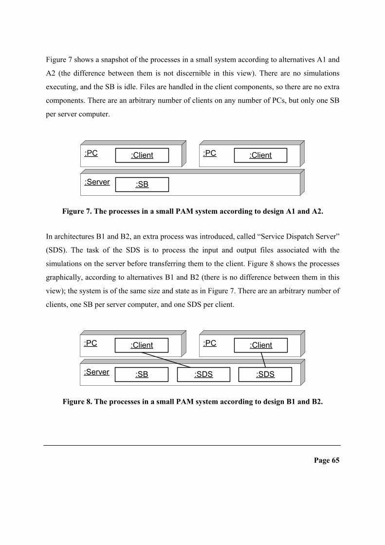
Figure 7 shows a snapshot of the processes in a small system according to alternatives A1 and
A2 (the difference between them is not discernible in this view). There are no simulations
executing, and the SB is idle. Files are handled in the client components, so there are no extra
components. There are an arbitrary number of clients on any number of PCs, but only one SB
per server computer.
:PC :Client
:Server :SB
:PC :Client
Figure 7. The processes in a small PAM system according to design A1 and A2.
In architectures B1 and B2, an extra process was introduced, called “Service Dispatch Server”
(SDS). The task of the SDS is to process the input and output files associated with the
simulations on the server before transferring them to the client. Figure 8 shows the processes
graphically, according to alternatives B1 and B2 (there is no difference between them in this
view); the system is of the same size and state as in Figure 7. There are an arbitrary number of
clients, one SB per server computer, and one SDS per client.
:PC :Client
:Server :SB
:PC :Client
:SDS:SDS
Figure 8. The processes in a small PAM system according to design B1 and B2.
Page 65

We can clearly see that there are more components and dependencies in B1 and B2 than in
architectures A1 and A2. The question to be analyzed is whether the expense in complexity
pays off with other advantages, such as increased performance.
4.3 The Analysis of the Architectures
We will now describe how performance, system load, and maintainability were estimated
from the architectural description.
Performance Analysis
As is described above, large files are sometimes transferred over the network, affecting
performance negatively. In the performance analysis, the number of large data transfers over
the network were measured or estimated. To be able to do this, we used five user scenarios
including network transfers of large pieces of data, such as “a simulation is executed” and
“two files are compared”.
The number of actual transfers during each scenario was estimated, and the result of this
analysis can be seen in Figure 9. As an example, the figure describes that for scenario 1 (“a
text file from a server computer is viewed in a client”) architectures A1 and A2 include one
transfer, not necessarily of the whole file (depending on the circumstances), for alternative B1
always exactly one whole file, and for B2 between one and two whole transfers of a file.
Architecture B2 clearly performed worst in all scenarios, A1 and A2 was equal in all but one
scenario, and it can be argued which of A1 and B1 performed absolutely best. A more
detailed analysis would include determining an average size of the data and weighting the
scenarios. For our purpose, however, this analysis was considered enough – we found that one
architecture (B2) was worst, and the others comparable when considering network load due to
large file transfers.
Page 66 Chapter 4: System Redesign Case Study

B2B1B1
B1
A1 A2A2A1
Scenario 1 Scenario 2 Scenario 3 Scenario 4 Scenario 5
2
1
A1
A1
A1
A2
A2 A2
B1 B1
B2 B2 B2 B2
Num
ber of data transfers (files)
Figure 9. The number of large data transfers across the network in five different
scenarios.
System Load Analysis
In the system load analysis, the number of processes in a running system was calculated. This
was thus not a SAAM analysis, but rather a simple addition of processes, based on the
number of server computers and an estimated average number of clients and simulations
(“small”, “medium”, or “large” systems). As is shown in Figure 10, the number of processes
is consistently lowest for architectures A1 and A2, while the number of processes may be
almost doubled in architecture B1.
Before performing this analysis we had no clear notion of what the outcome would be, but
when looking at these results in retrospect, we found them to be very intuitive. The extra
processes in systems according to B1 and B2 are due to the inclusion of the SDS component.
The great difference between B1 and B2 are due to the strategy on which servers there must
be SDSs, which in its turn depends on whether the simulation files are stored using a central
or a distributed approach.
Page 67

0
100
200
300
400
500
600
700
Small Medium Large
System size
Num
ber o
f pro
cess
es
A1A2B1B2
Figure 10. The number of processes in running systems of different sizes.
Maintainability Analysis
The stakeholders formulated 16 change scenarios, containing the addition of functionality. An
example of a change scenario is to “include functionality to compare two binary output data
files”. The results from the execution of these scenarios are presented in Table 2 – it turned
out that architectures A1 and A2 were undistinguishable, as was B1 and B2. Architectures A1
and A2 in general score better than B1 and B2, which of course is because architectures B1
and B2 include more components (the SDS). However, two scenarios affect the SB in
architectures A1 and A2, which is undesirable because of its central position and the
robustness requirements.
Page 68 Chapter 4: System Redesign Case Study

Table 2. Statistics from the scenario executions.
A1/A2 B1/B2
Number of components affected: total (average) 23 (1.4) 28 (1.8)
Number of scenarios affecting at least 2
components
6 10
Number of scenarios affecting the SB 2 0
Scenarios are said to interact on a component if both affect it [12]; if several unrelated
scenarios affect the same component, this is an indication that the separation of concerns
between components may be insufficient. The more interactions, the more complex it is to
maintain the system. However, as always there are no absolute numbers on how many
interactions are considered “too many”; these numbers should rather be used for comparing
architectures (which is done here), or to focus attention on particular components with many
scenario interactions. See Table 3.
With only five or six components and 16 scenarios, this analysis gives a rather decent
distribution, apart from the client. However, the client is equally unstable in all architectures.
How should we interpret these results? The figures clearly say that architectures A1 and A2
are more maintainable than B1 and B2 and seem to leave no room for alternative
interpretations. However, this result is at least partly a consequence of the fact that some
functionality is added to an extra component, the SDS. If this means that architectures B1 and
B2 are more fine-grained than A1 and A2 it is not fair to compare the architectural
descriptions – they describe the system on different levels of abstraction. We considered this
objection seriously, and among other things tried to estimate the size of the code in the
components. We arrived at the conclusion that the client code would be slightly smaller in
architecture B1 and B2 than in A1 and A2, but that the program code of the SDS would be
substantially larger than the decrease in client code size. We finally decided that the
Page 69

architectures were indeed comparable, and the figures of the analysis fair. In addition to this,
we had gained the insight that B1 and B2 would require more coding, which speaks to their
disfavor.
Table 3. Scenario interaction on each component. (The variations depend on how certain
scenarios are implemented.)
A1/A2 B1/B2
Database Affected by 4 scenarios
SB Affected by 2 scenarios Affected by 0 scenarios
CS Affected by 3 scenarios
TCS Affected by 3 or 4 scenarios
Client Affected by 10 or 11 scenarios Affected by 9 to 11 scenarios
SDS N/A Affected by 7 or 8 scenarios
Other Analyses
Besides analyzing performance, system load, and maintainability, we informally evaluated
testability, reusability, and portability. However, these analyses did not reveal any differences
between the architectures – we therefore omit the details of the analyses.
However, the conclusion that several architectures are indistinguishable is also a valuable
result, from which it is possible to draw conclusions. Firstly, since these properties are not
affected by the choice of architecture, any of the alternatives can be chosen (as far as these
properties are concerned). Secondly, if these properties were considered crucial for the
system’s success, we might have devised more alternatives, to explore whether these
properties could be improved at the architectural level. SAAM can only compare different
alternatives, not give absolute measures of the quality properties, so the outcome could mean
“they are equally good” as well as “they are equally bad”. We did not pursue this track further
Page 70 Chapter 4: System Redesign Case Study
because we were confident that our understanding of how these properties were affected
ensured that these properties would not pose any major problem. So, thirdly, through the
analysis process itself, we had gained insight enough into the problem to make the decision
that further analyses were not needed.
At this stage, we summarized the analysis and found performance, system load, and
maintainability to be the properties distinguishing the alternatives.
Discussion
It was not easy to without aid predict which architecture would be the most fit for our
requirements. The analyses clearly helped serving as a basis for a choice. We found that
architecture B2 was inferior with respect to the number of large data transfers, while B1 was
inferior with respect to the number of processes in the system. So far, if performance is
important, either architecture A1 or A2 should be chosen; A1 was estimated to have slightly
better performance than A2.
When evaluating maintainability, we see that A1 and A2 are superior, the only problem being
that two change scenarios affect the SB, whereas in B1 and B2 the SB is unaffected by all
scenarios. In other analyses the architectures were found to be equal.
It is quite clear, then, that architecture A1 or A2 should be chosen.
4.4 General Observations and Lessons Learned
Processes or Threads
So far, we have described the runtime components as “processes”, but the architectural
description does not require the CS and TCS components to be implemented as separate
operating system processes. They could very well be implemented as threads executing in a
designated “CS and TCS host” process, or why not in the SB. The choice between processes
and threads can be considered a lower-level design issue. This does not mean that the choice
does not affect the properties of the system, but rather that this tradeoff does not need to be
solved on the architectural level. There might indeed be a tradeoff between system load and
Page 71
robustness – processes load the system more, while a failure in one thread is likely to affect
other threads. In the actual implementation of PAM, it was decided that the system would be
more robust if processes are used in the case of a component failure, and that a threaded
solution would be considered if there were any system load problems.
We can draw the general conclusion that an architectural description does not need to
distinguish between processes and threads, but can simply describe the runtime components
as “separate threads of execution”. The choice of whether these are implemented as processes,
operating system threads, or language-level threads can be postponed to later design stages.
Detailed Knowledge Useful
One possible source of instability in the system would be that the system is spammed with CS
and TCS components having lost contact with each other. However, instead of being a
potential source of instability, the communications channel is used to increase robustness.
Sockets proved to fulfill our expectations well. Indeed, the knowledge of the socket
mechanism was an important input to the creation of the architecture. Let us view the
connection between a CS and one of its TCSs. Both sides will be noticed whenever the socket
is unexpectedly closed, and immediately terminate themselves. The socket could be closed
due to several reasons – the network might be lost, or the other component can have failed or
terminated unexpectedly (due to e.g. a bug). The components show a consistent behavior in
all such cases, provided that the sockets mechanism is reliable enough to always notice these
cases (which we believe it is). Thus, the architecture builds robustness partly on the sockets
mechanism.
Since we wanted to reuse legacy code written in the Tcl programming language [162], we
knew in advance that Tcl was a strong candidate of implementation language. Our experience
of the socket functionality being very robust and easy to use in Tcl strongly influenced the
development of the architecture as described above. We also knew that the use of Tcl would
support portability since there are Tcl interpreters available on the platforms of interest; as a
consequence we found it superfluous to support portability in our architectural description.
Page 72 Chapter 4: System Redesign Case Study

The general conclusion to be drawn is that detailed technical knowledge is an important input
to the architectural design process.
Simplicity Implies Robustness
Our next observation concerns another way the system is made robust. In earlier prototypes of
the system, there were problems with robustness. There were many scenarios where a failure
in one process made other processes fail too. Attempts were made to handle every possible
faulty state, but this proved to rather introduce new errors and make the code
incomprehensible. One of the governing ideas behind the new architectures has been to make
the runtime components as independent of each other as possible, in the sense that the system
as a whole is in a sound state even if many individual components and communication
channels fail. It should be noted that this feature is not implemented through any advanced
fault-tolerance techniques, but rather by creating a relatively simple architecture. Of course,
the robustness, as well as any quality attribute supported by the architectural description, is
ultimately dependent on how well the system is actually implemented.
Our experience supports the idea that one should build important properties directly into a
system’s architecture, rather than try to add them afterwards [12].
An Unexpected Solution of a Tradeoff
When discussing the outcome of the evaluation, there were a few minor issues that needed
more consideration, of which we will describe one. As we saw, the results of the analysis
indicate that we should choose between A1 (with a distributed file structure) and A2 (with a
central file structure). On the one hand, the project group intuitively felt uncomfortable with
the idea of having files distributed over a large number of computers when tracking errors,
while on the other hand this implies slightly higher performance. When considering this
problem, it seemed as we had to decide on a tradeoff. This proved to be both true and false.
We found that the choice of strategy where to store files did not need to be decided upon until
installing a PAM system, thus making a system administrator responsible for solving this
tradeoff (for it is indeed a tradeoff). We decided that viewed this way, the resulting
Page 73

architecture could be described as a synthesis of A1 and A2, or in other words that there was
no difference between A1 and A2.
In the general case, instead of making tradeoff decisions during the design phase, it might be
possible to give the system manager the freedom to choose the tradeoff considered optimal in
his particular situation. We believe that one should consider whether a tradeoff can be
postponed to the configuration and maintenance phases. However, we are aware that such an
approach may introduce new tradeoffs: a highly configurable system may be harder to
understand and maintain, and harder to test, than a less configurable system.
4.5 Conclusion
We devised one architecture, but created four variants of it and compared these at the
architectural level to be able to assess the quality attributes of the final system. SAAM
provided a useful way of evaluating our four suggestions, revealing drawbacks not obvious at
first sight. The analysis provided a basis for taking conscious decisions on which architecture
to choose, given an estimate on what quality attributes the four variants would have. The use
of SAAM proved to bring more benefits: the stakeholders of the system became more
conscious of quality attributes and the architecture’s impact on these; moreover, a fruitful
interaction between analysis and design took place thanks to SAAM.
Besides supporting the usefulness of SAAM, we were able to draw a number of general
conclusions. We learned that the creation of an architecture cannot be performed in an “ideal”
world, rather the knowledge about the availability of implementation issues are both
necessary and advantageous. In our case, the architecture was colored by the knowledge of
specific Tcl and sockets features, and this knowledge was taken advantage of to create a
robust architecture. We achieved a certain degree of robustness due to inherent features of the
architecture, which is preferable to writing error-handling code. During the design process,
we found it useful to discuss the runtime components in terms of “processes”, although it was
not decided whether these should actually be implemented as processes or threads. We have
also described that it was possible and useful to postpone one tradeoff decision to the system
Page 74 Chapter 4: System Redesign Case Study

configuration and maintenance phases. With further research we hope that these issues will
mature from mere observations to more formal models incorporated into the theory and tools
of software architecture.
During the analysis, the important question was raised whether the architectural descriptions,
containing different numbers of components, actually were comparable. We were able to give
what we believe to be a satisfactory answer by estimating the size of each component. With
further research it might be possible to more formally decide when architectural descriptions
differ too much and when they indeed are comparable – a prerequisite for any analysis.
Finally – what is our study worth for the stakeholders of PAM? Are our estimates of
performance, system load and maintainability accurate? Is the system robust and portable
enough? We will not be able to answer these questions until PAM has been in production use
for some time. We hope that we will then be able to gather measures of the quality attributes
of interest and compare it to our analysis. This will provide useful feedback to our research.
Page 75

5. INTEGRATION FRAMEWORK CASE STUDY This chapter presents an integration framework and discusses benefits and drawbacks with it.
Original publication information:
Information Organizer – A Comprehensive View on Reuse [62]
Erik Gyllenswärd, Mladen Kap, Rikard Land, 4th International Conference on
Enterprise Information Systems (ICEIS), Ciudad Real, Spain, April 2002
Keywords: Reuse, integration, legacy systems, Business Object Model, software
components, extensible, lifecycle support.
Abstract: Within one organization, there are often many conceptually related but
technically separated information systems. Many of these are legacy systems
representing enormous development efforts, and containing large amounts of
data. The integration of these often requires extensive design modifications.
Reusing applications “as is” with all the knowledge and data they represent
would be a much more practical solution. This paper describes the Business
Object Model, a model providing integration and reuse of existing applications
and cross applications modelling capabilities and a Business Object Framework
implementing the object model. We also present a product supporting the model
and the framework, Information Organizer, and a number of design patterns that
have been built on top of it to further decrease the amount of work needed to
integrate legacy systems. We describe one such pattern in detail, a general
mechanism for reusing relational databases.
Page 76 Chapter 5: Integration Framework Case Study

5.1 Introduction
It is commonly believed that software reuse put into practice would solve many problems
related to software development [8,100]. There are many aspects of reuse: one can (at least in
theory) reuse anything from mere concepts to data, information, program code, and
executable components (see e.g. [100]). However, in spite of the potential benefits of reuse, it
has proved hard to put reuse into practice in a large scale. Related to reuse is the idea of
integration – many organizations have a large number of legacy systems; an integration of
these would provide great benefits by increasing the possibility to provide appropriate and
related information in a timely manner. Is there any elegant solution to both of these problems
– reuse and integration? We believe there is. In this paper we present a model for integrating
existing applications, information and component reuse. The model is intended to cope with
all aspects of an object and extensible enough to be used during the whole lifetime of a
system.
The concept of reusing whole applications has been somewhat neglected in discussions of
reuse. With this, we do not mean modifying applications to include new functionality, but
rather to reusing whole applications, “as is”, without need of access to source code,
recompiling, reconfiguration or any other modification whatsoever, much like “components”
as defined by Szyperski [179]. If this is possible, integration is facilitated at a very low cost.
Such attempts have been done [133,134,138] but have mostly been focused on debating the
different competing standards for interoperability. Other attempts [1,73,96] focus more on
information reuse and integration.
We have developed the Business Object Model, BOM, which defines a conceptual model for
the integration of applications. To make BOM “come alive”, it has been implemented in
Business Object Framework, BOF. This implementation is the “core” of Information
Organizer, a commercial product itself made possible through extensive reuse. Information
Organizer has been used as the base for the implementation of several application patterns,
such as a pattern for workflow applications and a pattern for database connection. For
Page 77

applications conforming to these patterns, it is possible to configure them to a particular
organization’s need with a minimum of effort.
We will thus cover three aspects of reuse throughout the paper: reuse of existing applications
(through integration in a larger system) , reuse of application patterns, and reuse to make the
construction of Information Organizer possible.
We will use Information Organizer as a starting point and describe the features of the model
and how it is realized in a framework in section 5.2; we then continue by describing the
application patterns in section 5.3, and conclude with a discussion and a summary in sections
5.4 and 5.5.
5.2 The Model and the Framework
The Business Object Model, BOM, is a model which extend the concept of “directory enabled
applications” [72,92,129,161] with important capabilities for integration and modelling
inspired by OMG [138] and IEC 1346-1 [73]. The Business Object Model, BOM, represents
different entities of importance in a uniform way to the user. Business Object Model defines
five central concepts: objects, aspects, roles, relations and views. Objects represent quite
large grained entities such as issues, pumps or valves. An object can be described as an empty
container; business logic is added in form of aspects. An object can play a number of roles,
implemented by means of aspects. A relation connects objects, and finally, the concept of
views provides a means to restrict access to a system and all its information.
While the Business Object Model is a conceptual model, the Business Object Framework,
BOF, is a design environment provided to assist application programmers in building
components and applications, and integrating existing applications. BOF thus provides an
implementation of objects, aspects, relations, views and roles, as defined by BOM. It also
contains tools for creating instances of these, finding them in a distributed environment and
communicating with them. Business Object Framework can be described as a toolbox with a
number of tools and software components common to different applications for effective
Page 78 Chapter 5: Integration Framework Case Study

reuse. The Business Object Framework is thus the implementation of BOM; it is based on
Microsoft Active Directory and COM, and follows existing standards and de facto standards.
Business Object Model - BOM
We have designed Business Object Model to support cross-application integration and to be
easily extensible. It supports integration through the means of aspects: different aspects can
be associated with completely different systems. It is extensible in that an object can be
extended with new aspects during its entire lifetime (without affecting other aspects of the
object). It is important to understand that this model is independent of the manner in which
the different external systems model their part of the entire activity; BOM resides “above” the
systems it integrates – these systems need not be “BOM-enabled” in any way.
The five central concepts of the Business Object Model – objects, aspects, relations, roles,
and views – are described in more detail below. Their relationships between these are also
described in Figure 11.
Aspect
Business Object
1
0..n
1
0..n
Relat ion
2
*
2
*
View
*
*
*
*
* ** *
**
**
Figure 11: The relationships between the concepts.
Page 79

Objects – The most central concept of BOM is the concept of objects (or business objects, to
distinguish our notion from other uses of the term); these represent entities of interest in one
or several applications. Examples of objects are issues, steps in a workflow, organizations,
departments, or pumps and valves. An object usually contains very little, if any, information
or implementation in itself. Rather, objects offer a uniform way to assemble related
information through the concept of aspects.
Aspects – Instead of attempting to permit an object itself to represent all its behavior, part of
its behavior is delegated to different aspects. This means that new aspects can be added to the
object at any time during its entire life without necessarily affecting other aspects or the
object itself. Objects and aspects offer the possibility of componentizing applications in a
natural manner due to the fact that new business logic can be added to the object when the
object is ready for a new role (roles are explained below). Aspects can either contain all
business logic themselves or be used to associate existing applications or parts of existing
applications with an object and thereby their reuse. For an issue, aspects could include mail,
Excel sheets, PowerPoint presentations, reports, or video sequences; for objects in other
domains, examples of aspects are process dialogs, CAD drawings, and invoices. It should be
emphasized that both objects and aspects are complex entities, encapsulated into the system
without applying any changes on the components themselves.
Relations – To be able to build a usable information system, objects can be related to other
objects. The Business Object Model offers a relation model with both generic relations and
typed relations i.e. relations with a strong semantic significance. New relation types can be
defined in the system during its service life. Any number of relations can be associated with
an object, and in this way both hierarchic structures and net structures can be built. New
relation instances can be associated with an object at any time. This means that new relations
can be associated with an object even if the object cannot utilize them, because the object is
not aware of the relation and not implemented in such way that the relation can be used;
however, these relations may be useful if an external user understands them and can interpret
Page 80 Chapter 5: Integration Framework Case Study

their semantics. With “external user” we mean both other applications and human users
browsing through the information. Relations and aspects often occur together since aspects
provide the semantics with which it is possible to interpret and utilize the relation. By
extracting the relations and locating them outside the object, the architecture becomes
adaptable in a changing world as new types of relation and instances can be added to the
system, without affecting the existing functionality. This introduces a risk, however, since an
object may assume that certain relations are present that has in fact been removed (without the
object being informed).
Roles – The concept of roles is somewhat abstract, and must be seen in connection with
objects, aspects, and relations. To take a simple example, a “person” object may play the role
of a husband – to be able to play this role, it must have certain aspects, such as “being male”
and “being grown-up”. A more business-oriented example of a role is “to be participant in a
workflow”. A role can thus be said to define a certain function, or a set of capabilities, that
can be offered by an object, and it is implemented by one or more aspects. A relation type
associates two roles. A generic relation can associate any types of object as all objects are of
the generic type.
Views – Views make possible the arrangement of objects, aspects and relations to limit the
extent to which they are accessible to different categories of users. This is necessary, partly
because certain information is classified but also to reduce the volume of information
presented to make it easier for the user to understand. Initially, a system most often contains a
number of predefined views. A selected object will remain in focus if the user changes view
– this is useful when a user finds an object in one view (such as his personal view) and
changes to another (e.g. a process view, describing the object in the context of a workflow).
The concept of views is very important when integrating different systems – a personal view
would e.g. show all issues per individual, even if the issues originate from different issue
management systems. Views can of course be added in the same dynamic manner as objects,
aspects and relations.
Page 81

Let us illustrate the relations between the five concepts using an example. In the center of
Figure 12, there is a business object (BO) representing an issue in an issue-management
system. With the circle we try to describe the visibility of the object in different views; in an
issue-management system we can easily imagine the following views: a personal view
showing all the persons dealing with issues and the issues for which they are responsible, a
process view showing the issue’s location in a workflow, and an organizational view
describing the organization and all its employees. In the personal view, the issue and its
relation to a user (its “owner”) are visible; the object also has the aspect “A-Notes” indicating
that personal notes has been added to it. To be able to participate in a , the issue has been
allocated the aspect “A-Workflow” and a relation to a workflow step; when the issue is
processed, this relation will move to the next step (there are of course more steps visible in
the process view than is shown in the figure). The organizational view shows how the
organization is structured and, for each organizational unit such as a department, the issues
associated with the department concerned. The aspect “A-Document” is placed on the white
line to indicate that the document is visible in both the organizational view and the process
view.
A user interested in how far in the workflow an issue has progressed can either browse
through the process view to the issue of interest, or enter via another view, e.g. the personal
view, find the object, select it and then change to the process view. The issue will then be in
focus but visible in the process view, with the relevant relations and aspects.
Business Object Framework - BOF
Business Object Model is just a model, requiring considerable support in the form of tools
and default implementations to be usable. Business Object Framework provides this support
as a set of tools for building business objects. Some of these tools and functions are:
– A generic implementation of aspects, objects, views and relations.
Page 82 Chapter 5: Integration Framework Case Study
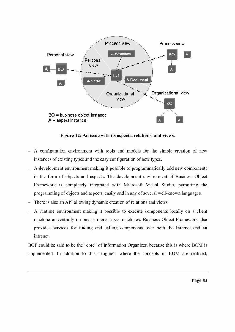
Figure 12: An issue with its aspects, relations, and views.
– A configuration environment with tools and models for the simple creation of new
instances of existing types and the easy configuration of new types.
– A development environment making it possible to programmatically add new components
in the form of objects and aspects. The development environment of Business Object
Framework is completely integrated with Microsoft Visual Studio, permitting the
programming of objects and aspects, easily and in any of several well-known languages.
– There is also an API allowing dynamic creation of relations and views.
– A runtime environment making it possible to execute components locally on a client
machine or centrally on one or more server machines. Business Object Framework also
provides services for finding and calling components over both the Internet and an
intranet.
BOF could be said to be the “core” of Information Organizer, because this is where BOM is
implemented. In addition to this “engine”, where the concepts of BOM are realized,
Page 83
Information Organizer includes other features, such as a user interface. The primary user
interface for a user of the system is a standard browser. The system is largely based on the
concept of “thin clients”, even if “fat clients” are used with respect to certain functions and
applications. An advantage with thin clients is that no code need be installed and maintained
on the client machine. But if the system integrates legacy applications built without the
Internet being taken into consideration, these applications must be installed in each client
machine anyhow. The system also provides support for access to information via WAP.
Structuring and Search Mechanisms
The problem in large systems is not lack of information. The problem is often defective
mechanisms to keep related information together and ways to find accurate information when
needed. This is one of the key problems we tried to solve with the Business Object
Framework. That is why the framework provides three major ways to structure and search
information.
– The first way is the most fundamental and is provided by the core of the framework and
the object model. Information can, as we have described, be structured in form of objects
in both multiple structures and multiple views. This can be used to create information
models spanning several integrated applications.
– The Relational Database Connector is the second way to search for information. As good
as every application has its own information model – i.e. internal structures. In case of
database applications these structures are very often represented as database relations. The
design pattern implemented in the Relational Database Connector provides a common way
to follow these relations via an Internet-enabled user interface regardless of from which
applications they originate.
– The third way is based on the concept of indexing. The basic idea is that information
visible to a user can be indexed; usually it means that different kinds of files (such as
documents) are indexed. Due to the fact that very much information is presented in the
form of generated cards it is important that these cards can be indexed and in case of a hit
Page 84 Chapter 5: Integration Framework Case Study

the object represented by the card presented. By doing this, information in the system can
be searched in the same familiar way as on the Internet; for example, keywords such as
AND, OR and NEAR can be used.
Our experiences are that in large systems with huge number of objects the more static way to
structure information is used to a less extent. The choice of structuring mechanism also
depends on the nature of the application domain. In for example the automation industry some
structures are of a quite static nature such as a structure representing the physical location of
equipment. Thus are these structure quite familiar to people and they are used to follow for
example the location structure to find a pump and all its aspects.
On the other hand when it comes to for example an issue management system people are very
much influenced of the way information are structured and search for in a relational database.
They are used to search for information in a variety of ways, which are impossible to foresee,
and therefore more static structures cannot be used.
Integration
Aspects represent information included in the integrated system. The aspects can integrate
information on different levels – at least three levels of integration can be identified:
application level, business logic level and data level.
If the system is integrated on the application level, the application does not provide an API to
its internal parts. When the application is referred to from an aspect, the application will be
activated and the user will enter at the top level and is required to navigate to that part of the
application at which the object (e.g. an issue) concerned is located.
Page 85
To be able to integrate on the level of business logic the application must be componentized
or provide an API permitting access to its different parts. I.e., when called, the application
could itself receive a number of input parameters describing the part in which the user is
actually interested and with the help of this information, navigate to the part concerned. The
input parameters very much depend on the application to be integrated and are often stored in
the aspect instance. The aspect can be seen as a gateway in between the framework and the

integrated application. The complexity of the aspect implementation very much depends on
the level of integration but also which kind of application to be integrated. If the application is
COM based it is very likely to be easier because the framework itself is COM based. To
manipulate the data, in this case an issue, the application’s own dialogs are used i.e. its own
business logic. For the user, a modular/component-based picture of the integrated application
would be presented even if it is not implemented in a component-based manner.
Integration at data level means that data is accessed directly without invoking the business
logic (code), which the integrated system itself makes available for the presentation, and
processing of data. In many applications, this is an appropriate level of integration. It can be
used to present information from many different systems but to change data, system dialogs
already available should be used. The Relational Database Connector, described in section
5.3, is an example of a component providing support for the integration of applications on this
level. By using the connector information stored in a relational database can easily integrated.
If data is stored in some other data source a specific connector for that particular data source
must be implemented. In practice, this level has been found to be very useful as a rapid
integration can be performed and Business Object Framework features (such as access
control) can be applied to each row in the database because they are represented as Business
Objects.
Integration at data level is most often a suitable level of ambition at which to begin. The level
of ambition can be raised subsequently and integration can then be performed on the business
logic level.
5.3 Application Patterns – One Way of Reuse
A design pattern is a solution to a problem that occurs over and over again [28,55]. We have
identified three major application patterns and implemented these in Information Organizer,
using Business Object Framework and the concepts defined by the Business Object Model.
With an application pattern, we mean a solution to a problem that occurs in many
applications, such as a “workflow” pattern. In our case a pattern is implemented as a number
Page 86 Chapter 5: Integration Framework Case Study

of objects, aspects, and relations. These patterns present a number of benefits: first, they are
common to many applications and can thus be used in many contexts, and secondly,
application boundaries are crossed. Moreover, due to the modular model of BOM, several
patterns can be applied simultaneously; any object can be extended with the aspects
implementing a pattern. We have used a number of patterns in practice when developing a
document and issue-management system [38].
Patterns Implemented
The following three major application patterns have been implemented.
Business Process Support, BPS, provides support when building workflow applications,
such as issue-management systems. This pattern is applicable when the items handled by the
system flows between steps or phases, such as in a system implementing the review process
of a scientific paper. Such systems are relatively easily built using the implementation of
objects, aspects etc. that makes up this pattern. Worth to note is that BPS provides workflow
functionality extending beyond application limits.
Document Management Support, DMS, supports management and generation of documents
over the Internet, using templates and information from objects associated with the document.
The template’s “hot spots” are filled dynamically with information from business objects.
One use of this pattern would be generation of reports on the history of an issue: dates of
completion and names of people associated with different workflow steps would be filled in
dynamically.
Relational Database Connector, RDC, provides a function by means of which, with the
assistance of XML, external relation databases can be defined and imported. To import a
database means that all the database objects are represented in Information Organizer but the
data itself remains in the database. The RDC also provides support for building dialogues,
which can present information from one or more data sources, and support for simple
navigation between different lines in a database. All such navigation is performed with the
help of URL’s. In an imported database, all rows are represented as Business Object
Page 87
Framework objects which in turn means that they acquire all the properties which characterize
a Business Object Framework object, such as strong security, the ability to keep all aspects of
an object together. One feature worth to note is that security on row level can be obtained
since Information Organizer represents each row in the database by an object, and the security
properties can be set on each object independently.
The rest of section 5.3 discusses the Relational Database Connector in more detail.
Relational Database Connector
Many database applications have very little business logic and provide some kind of standard
mechanism for accessing data directly (usually SQL). From the integration perspective, a
viable solution is thus to provide such a generic front-end “connector” as we have done; it
understands the target application’s data (relational database concepts in this case) and
provides components capable of encapsulating data from external databases for management,
navigation, access and manipulation purposes. Since such a connector has no business logic
whatsoever, it is unable to replace the original application entirely, but according to our work
it can usually provide 60 to 80% percent of the original application functionality without any
extension. The business logic of an application is however less often restricting “reads”, and
more often of the kind restricting how data can be modified or added. If an application
contains much such logic, it is still possible to integrate database access but only permit reads.
Such read-only integration can be of great benefit, if use cases including only reads are more
common than use cases including writes.
Since the connector is generic, it is highly reusable because it can solve integration problems
for many target applications with similar problems. An additional benefit is that the RDC
components are fully integrated into the framework and can thus offer a much broader range
of functions than that of the original application.
Page 88 Chapter 5: Integration Framework Case Study

Description Files in XML
To define which parts of a database should be represented by objects in Active Directory, and
how to present and interact with the database data, a number of XML description files are
used. For each table in the database, three XML files have to be defined.
– The first one is mainly used to describe the table’s columns and their data types. For each
column it is possible to define whether it is editable or not and if a new data item has to be
initiated or not. Related tables can also be described; for example, in a file describing a
“decision”, information is provided in form of keys to be able to find a way back to the
correct issue. And in the “issue” object, file information is provided to be able to present
the owner of, or all documents belonging to the issue.
– The second file defines how information can be presented in “summary cards”, and
describes available predefined queries. Whenever a row is selected in table, the data is
presented according to the specification in the file. The XML file can of course be edited,
and thus the summary card’s appearance is modified. This approach provides an easy way
to configure displays for different tables within a database, but also to present information
originating from different database systems in a homogeneous manner. These summary
cards are also the foundation to provide a powerful and common search mechanism for
different information systems, integrated in Information Organizer.
– The third file provides means to map to the language of your choice.
The business logic using the description files are implemented as a number of Active Server
Pages and COM objects.
5.4 Discussion
The following describes some of the lessons learned from practical experience gained from
the development of Information Organizer [40] and the document and issue management
system Arch Issue [38].
Page 89

Reuse
The overall and certainly the most important lesson learned is that reuse can be highly
profitable. For organizations with limited resources undertaking relatively ambitious
development projects, it is the only viable - and therefore practically mandatory - approach.
With a very limited investment, Compfab [39] was able to build a functionally comprehensive
framework for its intended purpose, which in addition is secure, scalable, and reliable. This
would not have been possible without total commitment to the reuse of not only platform
components, but also architectural and design patterns, as well as “best practices” known for
the platform.
We chose a set of standard products integrating e.g. Internet access and security. These not
only provide a runtime and design-time environment but also a large number of components
and knowledge of how to build user interface components. The word “build” was
intentionally used to emphasize that a significant part of the development time was spent in
learning the full capabilities and impacts of existing technologies and components on
functionality and features targeted in the resulting framework. Development of custom
functions for the framework actually occupied a smaller part of the total project time. Our
impression is that this is one of the main reasons why verbal commitments to component-
based development often fall short in practice.
Practical Experience
Information Organizer is currently used for developing an issue-management system [38], and
therefore our practical experience of using Information Organizer, and the concepts of BOM,
is somewhat limited.
However, experience from the application of the framework to real world problems only
reinforced most of the conclusions arrived at from experience from the development of the
framework itself. In general, integrating modern, well-componentized applications is easy and
straightforward, provided the application is designed to run on the same platform at which the
Page 90 Chapter 5: Integration Framework Case Study

framework is targeted (or provides “proxies” for accessing it when running on other
platforms).
Integrating monolithic applications with poor or no defined application programming
interfaces is difficult and cumbersome – sometimes to such a degree that the original
motivation for integrating such applications becomes highly questionable. For example, if
there is an order management application which encapsulates orders, customers, responsible
personnel etc into well defined components, and another invoice management application
which is monolithic and provides access to its logical parts only through the proprietary user
interface, there is no way to automate management of relations between logically related
objects in these two applications, even at the user interface level. Unfortunately, many
database-centred applications existing today are precisely of that kind. However, since many
of these applications have very little business logic but provide a SQL interface for data
access, the Relational Database Connector is a simple but very useful means to integrate
database applications in Information Organizer.
5.5 Summary
Reuse by integration of applications and information and reuse based on component-based
development are two equally important ways to improve software development. Information
Organizer emphasizes this and provides an object model, a framework and a number of
components to encourage the building of integrated solutions. By taking the concept of
“directory enabled applications” defined by Microsoft further by adding a number of
important properties defined in standards such as IEC 1346-1 (defining the concept of aspects
which relates all relevant information to an object), OMG (defining a powerful relation
model) and IT4 (defining a way to build integrated industrial applications), we have achieved
a strong and powerful environment based on a standard concept to build integrated systems.
The total commitment to reuse not only platform components, but also architectural and
design patterns and known “best practices” for the platform has been vital to the success of
building not only the product itself but also components and applications based on it.
Page 91

We have thus covered three aspects of reuse. First, with Information Organizer, implementing
the concepts of BOM, it is possible to reuse whole applications, not originally intended for
reuse. The level of integration can be chosen somewhat: either on user interface level or data
level (using Relational Database Connector). Second, using the BOM concepts, we have
implemented generic, i.e. reusable, application patterns. Third, we also described shortly how
reuse of existing technologies made Information Organizer possible.
In the future, we will explore how different categories of users react to an integrated approach
to different separate applications. How does the system respond to extremely large data
quantities? How well does it support the maintenance of relationships when the original data
sources changes? The “loose” coupling between objects and applications may prove to give
rise to maintenance and consistency problems.
Page 92 Chapter 5: Integration Framework Case Study
6. SYSTEMS INTEGRATION CASE STUDY This chapter describes a case study where three existing software systems developed in-house
were to be integrated after a company merger. We describe how architectural analysis was
used in this process, and the benefits and shortcomings of this approach. This case study is
also described in chapters 7 and 8 from other points of view.
Original publication information:
Software Systems Integration and Architectural Analysis – A Case Study
[106]
Rikard Land, Ivica Crnkovic, Proceedings of International Conference on
Software Maintenance (ICSM), IEEE Computer Society, Amsterdam, The
Netherlands, 2003.
Keywords: Architectural Analysis, Enterprise Application Integration,
Information Systems, Legacy Systems, Software Architecture, Software
Integration.
Abstract: Software systems no longer evolve as separate entities but are also
integrated with each other. The purpose of integrating software systems can be to
increase user-value or to decrease maintenance costs. Different approaches, one
of which is software architectural analysis, can be used in the process of
integration planning and design.
This paper presents a case study in which three software systems were to be
integrated. We show how architectural reasoning was used to design and
compare integration alternatives. In particular, four different levels of the
integration were discussed (interoperation, a so-called Enterprise Application
Integration, an integration based on a common data model, and a full
Page 93

integration). We also show how cost, time to delivery and maintainability of the
integrated solution were estimated.
On the basis of the case study, we analyze the advantages and limits of the
architectural approach as such and conclude by outlining directions for future
research: how to incorporate analysis of cost, time to delivery, and risk in
architectural analysis, and how to make architectural analysis more suitable for
comparing many aspects of many alternatives during development. Finally we
outline the limitations of architectural analysis.
Page 94 Chapter 6: Systems Integration Case Study

6.1 Introduction
The evolution, migration and integration of existing software (legacy) systems are widespread
and a formidable challenge to today's businesses [25,115]. This paper will focus on the
integration of software systems. Systems need to be integrated for many reasons. In an
organization, processes are usually supported by several tools and there is a need for
integration of these tools to achieve an integrated and seamless process. Company mergers
demand increased interoperability and integration of tools. Such tools can be very diverse
with respect to technologies, structures and use and their integration can therefore be very
complex, tedious, and time- and effort-consuming. One important question which arises: Is it
feasible to integrate these tools and which approach is the best to analyze, design and
implement the integration?
Architecture-centered software development is a well-established strategy [13,20,71,146]. We
have experienced the architecture of a system as an appropriate starting point around which to
concentrate integration activities. One common experience is that integration is more complex
and costly than first expected due to “architectural mismatches” [51,57], and this problem
should be addressed at the architectural level. It also seems possible that some architectural
analysis techniques used during new development could also be applicable during system
evolution and integration. In this paper we show the extent to which an architecture-centric
approach can be used during system evolution and integration, and how accurate and relevant
the result of such an architecture-based analysis is.
Our aim has been to present our experiences from a case study in which three software
systems were to be integrated after a company merger. We have monitored the decision
process, and the actual integration has just begun. The activities were focused around the
systems’ architectures. We describe the three integration approaches that were discerned and
discussed, how architectural descriptions of the two most interesting were developed and
analyzed and the decisions taken for the development project. Further we analyze the
proposed solutions showing the strong and weak sides of the architectural strategy as such.
Page 95

The rest of this paper is organized as follows. Section 6.2 provides the background of our case
study, section 6.3 discusses four integration approaches, and section 6.4 uses the case study to
elaborate on architectural analyses possible during system integration. Section 6.5 describes
related work, and section 6.6 concludes the paper and suggests directions for future research.
6.2 Introducing the Case Study
The case study concerns a large North American industrial enterprise with thousands of
employees that acquired a smaller (approximately 800 employees) European company
operating in the same business area. Software, mainly developed in-house, is used for
simulations and management of simulation data, i.e. as tools for development and production
of other products. The functionality of the software developed in the two organizations prior
to the merger was found to overlap to some extent, and three systems suitable for integration
were identified. A project was launched with the aim of arriving at a decision on strategic
principles for the integration, based on the proposed architecture for the integrated system.
This was the first major collaboration between the two previously separate software
departments.
Figure 13 describes the existing systems’ architectures in a simplified manner in a high-level
diagram combining an execution view of the system with the code view [13,35,71,98]. The
sizes of the rectangles indicate the relative sizes of the components of the systems (as
measured in lines of code). One system uses a proprietary object-oriented database,
implemented as files accessed through library functions, while the other two systems, which
were developed at the same site, share data in a common commercial relational database
executing as a database server. The most modern system is built with three-tier architecture in
Java 2 Enterprise Edition (J2EE), while the two older systems are developed to run in a Unix
environment with only a thin X Windows client displaying the user interface (the “thin” client
is denoted by a rectangle with zero height in the figure). These are written mostly in Tcl and
C++, and C++ with the use of Motif. The “Tcl/C++ system” contains ~350 KLOC (thousands
of lines of code), the “C++/Motif system” 140 KLOC, and the “Java system” 90 KLOC.
Page 96 Chapter 6: Systems Integration Case Study

Key
Server
UnixServer
Client
UnixServer
Client
Tcl
C++
DatabaseServer
C++
Server
Client
Java
Java
DataFiles
Process
File
File Access
Bidirected RuntimeCommunication
Figure 13. Today’s three systems.
6.3 Integration Approaches
When developing architectures of new systems, the main goal is to achieve the functionality
and quality properties of the system in accordance with the specified requirements and
identified constraints. When, however, existing systems are to be integrated, there may be
many more constraints to be considered: backward compatibility requirements, existing
procedures in the organization, possible incompatibility between the systems, partial overlap
of functionality, etc. Similarly, the integrated system is basically required to provide the same
functionality as the separate systems did previously, but also, for example, to ensure data
Page 97

consistency and enable automation of certain tasks previously performed manually. When
developing new software, it is possible to design a system that is conceptually integrated [27]
(i.e. conforms to a coherent set of design ideas), but this is typically not possible when
integrating software since the existing software may have been built with different design
concepts [57]. Another problem is how to deal with the existing systems during the
integration phase (and even long after, if they have been delivered and are subject to long-
term commitments). This problem becomes more complex the more calendar-time the
integration will take as there is a pronounced tradeoff between costs in the short term and in
the long term when different integration solutions have different maintainability
characteristics. For example, there is an opportunity to replace older with more recent
technologies to secure the system usability for the future. Scenarios possible if the systems are
not integrated should also be considered.
In the analysis and decision process we have discerned four integration approaches or
“levels” with different characteristics. They are:
• Interoperability through import and export facilities. The simplest form of using
services between tools is to obtain interoperability by importing/exporting data and
providing services. The data could either be transferred manually when data is needed, or
automatically. To some extent, this could be done without modifying existing systems
(e.g. if there is a known API or it is possible to access data directly from the data sources),
and if source code is available it is possible to add these types of facilities. This approach
would allow information to flow between the systems, which would give users a limited
amount of increased value. It would be difficult to achieve an integrated and seamless
process, as some data could be generated by a particular tool not necessarily capable of
automatic execution. Moreover, there would be problems of data inconsistency.
• Enterprise Application Integration (EAI). Many systems used inside a company are
acquired rather than built, and it is not an option to modify them. Such systems are used
within a company, as opposed to the software products a company not only uses but also
Page 98 Chapter 6: Systems Integration Case Study

manufactures and installs at customers’ sites. Integrating such enterprise software systems
involve using and building wrappers, adapters, or other types of connectors. In such a
resulting “loose” integration the system components operate independently of each other
and may store data in their own repository. Depending on the situation, EAI can be based
on component technologies such as COM or CORBA, while in other cases EAI is enabled
through import and export interfaces (as described in previous bullet). Well-specified
interfaces and intercommunication services (middleware) often play a crucial role in this
type of integration.
• Integration on data level. By sharing data e.g. through the use of a common database,
the users will benefit from access to more information. Since the systems store
complementary information about the same data items; the information will be consistent,
coherent and correct. However, it would presumably require more effort to reach there: a
common data model must be defined and implemented and the existing systems must be
modified to use this database. If this is done carefully, maintenance costs could be
decreased since there is only one database to be maintained and there are opportunities to
coordinate certain maintenance tasks. On the other hand, maintenance becomes more
complex since the database must be compatible with three systems (which are possibly
released in new versions independently). Also data integration may have an impact on
code change, due to possible data inconsistencies or duplicated information.
• Integration on source code level. By “merging” source code, the users would experience
one homogeneous system in which similar tasks are performed in the same way and there
would be only one database (the commercial database used today by the C++/Motif
system and the Java system). Future maintenance costs can be decreased since it would be
conceptually integrated, and presumably the total number of lines of code, programming
languages, third-party software and technologies used will decrease. Most probably the
code integration would require integration of data.
Page 99

Interoperability through import and export facilities is the most common way of beginning an
integration initiative [41]. It is the fastest way to achieve (a limited amount of) increased
functionality and it includes the lowest risk of all alternatives, which is the reason why
managers usually adopt this approach. In a combination with a loose integration (EAI) it can
provide a flexible and smooth integration process of transition: the import/export facilities can
be successively replaced by communicating components and more and more integrated
repositories. Of course, this approach has its disadvantages – in total it will arguably require
more effort, and the final solution may technically not be as optimized as the results of the
“data level” or “code level” approaches. This of course depends on the goals of the
integration.
Which integration approach to use in a particular context depends not only the objective of
the integration, but also e.g. the organizational context and whether source code is available
or not. For example, is the goal to produce an integrated product for the market, or is the
system to be used only in-house? Is integration of software a result of a company merger? Is
integration expected to decrease maintenance costs or to increase the value for users (or
both)? Who owns the source code? Can the systems to be integrated be expected to be
released in subsequent versions by (other) independent vendors? Is modifying source code an
option, considering both its availability and possible legal restrictions? Business constraints
also limit the possibilities – the resources are limited and time to market an important
concern. One must also consider the risks associated with each alternative, meaning the
probability of overrunning budget and/or schedule or not succeed with the integration. The
risk parameters include not only those related to technical problems, but also those associated
with the collaboration of two software development departments which had previously
belonged to different companies and only recently began collaborating.
The project team of the case study intuitively felt that the benefits and the cost of
implementation, the time to delivery, and the risk of the integration approaches described
above should be related roughly as shown in Figure 14. The diagram is very simplistic
Page 100 Chapter 6: Systems Integration Case Study

assuming there is only one “benefit” dimension, but as mentioned earlier there may be
different types of goals for integration, such as increased usability or decreased maintenance
costs. EAI was never explicitly considered as a separate approach during the case study and is
therefore omitted from the figure.
Cost,Risk,Time
Benefit
"Import/Export Interface"
"Data level"
"Code level"
Figure 14: Expected relations between risk, cost, and time to delivery.
6.4 Development of Integration Alternatives
Developers from the two sites met and analyzed the existing systems at the architectural level,
and then developed and analyzed two integration alternatives. The developers had architected,
implemented and/or maintained the existing systems and were thus very experienced in the
design rationale of the systems and the technologies used therein. The architectural
alternatives were then handed over to management to decide which alternative should be
used. The integration process was based on IEEE standard 1471-2000 [76] and is described in
more detail in [105,107].
The “import/export level” interoperability was not discussed in any depth since it was
apparent that more benefits were desired than could be expected with this approach. Instead,
the software developers/architects tried the other approaches to integration, by conceptually
combining the source code components of the existing system in different ways. The existing
documentation had first to be improved by e.g. using the same notation (UML) and the same
Page 101

sets of architectural views (a code view and an execution view were considered sufficient) to
make them easy to merge [107]. Each diagram contained about ten components, sufficient to
permit the kind of reasoning that will be described. By annotating the existing components
with associated effort, number of lines of code, language, technologies, and third-party
software used, the developers could reason about how well the components would fit
together. During the development of alternatives, statements about the quality properties of
the integrated system such as performance and scalability were based on the characteristics of
the existing systems. Patterns known to have caused deficiencies and strengths in the existing
systems in these respects made it possible to evaluate and discard working alternatives
rapidly. The developers had a list of such concerns, to ensure that all those of importance
were addressed. The process of developing and refining alternatives and analyzing them was
more iterative than is reflected in the present paper where we only present two remaining
alternatives and the analyses of three specific concerns in more detail (sections “Future
Maintainability” on page 104, “Cost Estimation” on page 105, and “Estimated Time to
Delivery” on page 107).
The two remaining main alternatives conformed well to the “data level” and the “code level”
integration approaches. Both these alternatives would necessarily need a common data model
and shared data storage. From there, the two different levels of integration would require
different types of actions: for “data level” integration, the existing systems would need to be
modified due to changes in the data model, and for “code level” integration, much of the
existing functionality would need to be rewritten in Java; see Figure 15. In reality, these
descriptions were more detailed than the figure suggests; About ten components were used in
each of the same two views for describing the existing systems, a code view and an execution
view.
Architectural descriptions such as these make it possible to reason about several properties of
the resulting integrated system.
Page 102 Chapter 6: Systems Integration Case Study

Server
UnixServer
Client
UnixServer
Client
Tcl
C++
Database Server
C++
Server
Client
Java
Java
a) "Data level" integration, preserves existingarchitectures
Server
Server
Client
Java or Tcl
Java
DatabaseServer
b) "Code level" integration, uses 3-tieredarchitecture
Figure 15. The two main integration alternatives.
Page 103
Future Maintainability
The following factors were considered in the case study to be able to compare the future
maintenance costs of the integration alternatives:
• Technologies used. The number of technologies used in the integrated system arguably
tells something about its complexity. By technologies we more specifically mean the
following: programming languages, development tools (such as code generators and
environments), third-party software packages used in runtime, and interaction protocols.
Too many such technologies will presumably create maintenance difficulties since
maintaining staff needs to master a large number of languages and specific products and
technologies, but at the same time tools and third-party software should of course be used
whenever possible to increase efficiency. A reasonable number must therefore be
estimated in any specific case. In our case study, the total number of languages and
technologies used in the “code level” alternative would be reduced to 6 to 8 languages
instead of the 11 found in the existing system combined, a number which would be
preserved in the “data level” alternative. The number of third-party packages providing
approximately the same functionality could be reduced from 9 to 5, and two other
technologies would also become superfluous.
• LOC. The total number of lines of code (LOC) has been suggested as a measure of
maintainability; it is e.g. part of the Maintainability Index (MI) [137,169]. In the case
study, the total number of lines of code would be considerably less with the “code level”
alternative. No numbers were estimated, but while the “code level” alternative would
mean that code was merged and the number of lines of code would be less than today, the
“data level” alternative would rather raise the need of duplicating more functionality in
the long term.
• Conceptual integrity. Although a system commonly implements several architectural
styles at the same time – “heterogeneous systems” [13] – this should come as a result of a
conscious decision rather than fortuitously for the architecture to be conceptually
Page 104 Chapter 6: Systems Integration Case Study
integrated [27]. In the case study, it was clear, by considering the overall architectural
styles of the systems, that the “data level” alternative involved three styles in parallel
while the “code level” would reflect a single set of design ideas.
It might seem surprising that in the case study, in the “code level” integration alternative, the
server is written totally in Java. Would it not be possible to pursue the EAI approach and
produce a loosely integrated solution, involving the reuse of existing parts written e.g. in
C++? With the platform already in use, J2EE, it would be possible to write wrappers that
“componentized” different parts of the legacy code. This was considered, and, by iteration the
architectural description of this alternative was modified and analyzed with respect to the cost
of implementation. Based on these estimates, all solutions involving wrappers and
componentization were ultimately discarded and only the two alternatives already presented
remained.
Whether to use Java or Tcl in the client for the “code level” alternative was the subject of
discussion. Much more user interface code was available in the Tcl/C++ system than in the
Java system which was preferable for other reasons. The pros and cons of each alternative
were hard to quantify, and eventually this became a question of cost, left to the management
to decide.
Cost Estimation
Estimating the cost of implementing an integrated system based on an architectural
description is fairly straightforward. Based on previous experience, developers could estimate
the effort associated with each component, considering whether it will remain unmodified, be
modified, rewritten, or totally new in the integrated system. Clearly, the outcome of this type
of estimation is no better than the estimations for individual components. The advantage of
estimation at the component level is that it is easier to grasp, understand, and (we argue)
estimate costs for smaller units than for the system as a whole.
This estimation is fairly informal and mainly based on experience, but it can be considered
reasonable. First, the developers in the case study were very experienced in the existing
Page 105

systems and software development, second, the developers themselves agreed on the
numbers, third, these numbers were higher than the management had expected (implying it
not being overly optimistic/unrealistic), fourth, management explicitly asked the developers
during the development of the alternatives to find cheaper (and faster) alternatives, something
they were unable to do – the only alternative according to them would be the import and
export facilities (for the interoperability approach). When summing the effort associated with
all components in each alternative the developers found (partly to their surprise) that the
implementation costs would be the same for both alternatives (the total estimated times
differed by only 5%, which is negligible for such early, relatively rough estimations). This
was true for the variant of the “code level” alternative if Tcl was chosen for the client part -
using Java would require more resources. The apparently high cost of the “data level”
alternative was due to the definition of a common data model, and in the case of the Tcl/C++
system the use of a new database (a commercial relational database instead of an object-
oriented proprietary database). These changes would ripple through the data access layer, the
classes modeling the items in the database, and to a limited extent the user interface. Since the
total number of lines of code is much greater than the estimated number of lines of code in the
“code level” integration alternative, the apparently lower cost of modifying code instead of
rewriting it would be nullified by the larger number of lines of code. It would also be
necessary to write some new components in two languages.
Bridging solutions would be required and functionality duplicated in both C++ and Java by
the existing code (and added to by the development of new functionality and the
modifications of e.g. data access layers). When the developers estimated the costs associated
with using both Tcl and Java in the client (since much code could be reused), and using only
one (thus extending the existing code in one language with the functionality of the other), it
was concluded that using two different languages in the client would probably be more costly
than using either one, due to the same arguments as above. Some generic components, among
them non-trivial graphical widgets, would need to be written in two languages.
Page 106 Chapter 6: Systems Integration Case Study
Building a common data model from existing data models is one of the major challenges of
software engineering [5,51], which was apparent from the cost estimations. We cannot claim,
on the basis of a single case study, that the “data level” approach will always be as expensive
as the “code level” approach, but this reasoning gives at hand that in general, neither
approach is cheap, once a minimum of data level integration is decided upon. For the “data
level” alternative this requires changes throughout the existing systems and the “code level”
alternative requires changes, to adapt to both the new data model and a single set of
technologies, languages, and architectural styles.
Estimated Time to Delivery
The resulting project plans developed in the case study are shown in Figure 16. Although the
diagrams presented here are somewhat simplified compared with those developed in the
project, they suffice to illustrate some features of this type of project plan:
• The definition of a common data model is crucial in both integration approaches, since
most other activities are dependent on it. In the case study, the developers were explicit
that this activity should not be rushed, and should involve the most experienced users as
well as developers.
• Management is given a certain amount of freedom by not assigning strict dates to
activities. Activities can be prioritized and reordered, and deliveries “spawned off” to
meet business demands. More staff can be assigned to certain activities to increase
parallelism and throughput. Based on which components would need to be included in a
delivery, it is possible to define activities that produce these components; for example, if a
delivery with functionality “X” is desired, the activity “Extend with functionality X” or
“New functionality X” (for the two alternatives respectively) must be performed as well
as all activities on which it is dependent. One strategy could be to aim at delivering a
“vertical slice” of the system, incorporating the functionality that is most used first. In this
way some users can begin using the new system, thus minimizing the need for
maintenance and development of the existing systems (which will soon be retired).
Page 107

• In the “code level” alternative, many activities are of the “transfer functionality” type. In
this way, users of the Java system will only see the functionality grow rapidly, but the
users of the other systems will experience a period when most of the functionality exists
in both the system with which they are familiar and the new system. For the “data level”
alternative, the activities are more of the kind “modify the existing systems”. The users
would then continue using their familiar system but, when beginning to use the other
systems, would have access to more functionality working on the same data. This type of
reasoning impacts on long-term planning aspects such as the time at which existing
systems can be phased out and retired.
• In the “code level” alternative, it was possible to identify more general components that
would require an initial extra amount of effort and calendar-time but would eventually
make the project cheaper and faster. In the “data level” alternative, only few such
components were identified.
• Some development of totally new functionality demanded by users was already planned
and could not be delayed until the systems integration efforts were completed. However, it
was agreed that these activities should be delayed as long as possible – at least until one
of the integration alternatives was chosen, and if possible, until the new data model had
been defined, and even general components implemented in the case of the “code level”
alternative. This was to avoid producing even more source code that would need to be
modified during the integration.
Page 108 Chapter 6: Systems Integration Case Study

C++/Motifsystem
Tcl/C++system
Javasystem
Replaceproprietarydatabase
Modifyclasses/user
interface
Generalactivities
Define datamodel
Developgeneral
functionality
Modifyclasses/user
interface
Extend withfunctionality
X
Modifyclasses/user
interface
Extend withfunctionality
Y
Extend withfunctionality
Z
Newfunctionality
W
Implement new functionality Transferfunctionality
Generalactivities
Define datamodel
Developgeneral
functionality
Newfunctionality
X
Newfunctionality
Y
Newfunctionality
W
Newfunctionality
Z
TransferfunctionalityA from Tcl/C++ system
TransferfunctionalityB from Tcl/C++ system
TransferfunctionalityC from C++/Motif system
b) Project schedule plan for "code level" alternative:
a) Project schedule plan for "data level" alternative:
Figure 16: The outlined project plans.
Page 109

The Decision
When the developers from the two sites had jointly produced these two alternatives and
analyzed them, the management was to decide which alternative to choose. It was agreed that
the “code level” alternative was considered to be superior to the “data level” alternative from
virtually all points of view. The users would experience a more powerful, uniform and
homogeneous system. It would also be easier (meaning less costly) to maintain. The analysis
had shown that it would include a smaller code base as well as a smaller number of
languages, third-party software, and other technologies. The languages and technologies used
were more modern, implying that they would be supported by more tools, easier to use and
more attractive to potential employees. Not least, the resulting product would be conceptually
integrated. Regarding the choice between using Java and Tcl in the client, the management
accepted that if the “code level” was decided upon, Tcl would be used since using Tcl implied
a significantly smaller effort (due to a larger code base to reuse).
When management considered all this information, they judged the integration to be
sufficiently beneficial to motivate the high cost. The benefits included, as we have indicated
earlier, increased user efficiency, decreased maintenance costs (in the case of the “code level”
alternative), as well as less tangible business advantages such as having an integrated system
to offer customers. Also, the evolution scenarios for the existing systems if no integration was
performed would be costly; for example, the European organization would probably replace
in the near future, the proprietary object-oriented database with a commercial relational
database for maintenance and performance reasons. The cost of implementing the “data level”
and “code level” alternatives (when using Tcl in the client) had been estimated to differ
insignificantly, and as the organization had to develop it with a limited number of staff, the
estimated time to delivery would also be very similar, although the deliveries would be of
different kinds due to the different natures of the activities needed for the two alternatives.
The relation benefit vs. cost and time to delivery can therefore be visualized as Figure 17
illustrates (the “import/export interface” level was not analyzed, hence the parentheses).
Page 110 Chapter 6: Systems Integration Case Study

Benefit
("Import/Export Interface")
"Data le
vel"
"Code le
vel"
Cost,Time
Figure 17: The estimated cost and time to delivery.
As became clear by now, it was less important to get as much benefit as possible for the cost
than to decrease the risk as much as possible. No formal risk analysis was performed at this
point, but the risk was judged to be higher for the “code level” alternative, since it involves
rewriting code that already exists and works, i.e. risking overrunning schedule and budget
and/or decreasing the quality of the product, but also a risk in terms of “commitment
required” from the departments of two previously separate organizations, not yet close
collaborators. By choosing the “data level” alternative, each system would still be functioning
and include more functionality than before, should the integration be discontinued due to e.g.
an unacceptable schedule and/or budget situation. This is discernible in the project plans of
Figure 16. Management doubted that the cost of the two alternatives would really be similar;
they intuitively assumed that the higher benefit, the more effort was required (cost and time),
as was sketched in Figure 14. Still, they were explicit in that the risk was the decisive factor
and not cost, when choosing the “data level” alternative.
6.5 Related Work
There are suggestions that project management during ordinary software development has
much to gain from being “architecture-centric” [146]. We have shown some ways of pursuing
the architecture-centric approach during integration also. The rest of this section will focus
Page 111
on two related aspects of this, the literature relating to integration approaches, and methods
and analysis techniques based on architectural descriptions.
Of the four integration approaches we have discussed, Enterprise Application Integration
(EAI) seems to be the most documented [44,62,82,115,154]. This approach concerns in-house
integration of the systems an enterprise uses rather than produces. Johnson [82] uses an
architectural approach to analyze the integration of enterprise software systems. In spite of the
difficulty of accurately describing the architecture of this type of system because the available
documentation is inadequate, architectural analysis can be successfully applied to the design
of enterprise systems integration. Johnson has also examined the limitations of architectural
descriptions which one must be aware of, limitations that were also experienced in the case
study.
None of the architectural methodologies available were completely feasible for the task. The
Architecture Trade-off Analysis Method (ATAM) [34] and the Software Architecture Analysis
Method (SAAM) [13,34] are based on stakeholder-generated scenarios. The ATAM requires
business drivers and quality attributes to be specified in advance and more detailed
architectural descriptions to be available. In the case study, all of this was done in a more
iterative manner. Also, with limited resources, it would be impossible to evaluate and
compare several alternatives, it being too time-consuming to investigate all combinations of
quality attributes for all working alternatives. While both SAAM and ATAM use scenarios to
evaluate maintainability, we used another, if less accurate measurement method, comparing
the number of lines of code, third-party software, languages, and technologies used, assuming
that the lower the number, the easier the maintenance. The Active Reviews for Intermediate
Designs method (ARID) [34] builds on Active Design Reviews (ADR) and incorporates the
idea of scenarios from SAAM and ATAM. It is intended for evaluating partial architectural
descriptions, exactly that which was available during the project work. However, it is
intended as a type of formal review involving more stakeholders and this was not possible
because the project schedule was already fixed, and too tight for an ARID exercise. All of
Page 112 Chapter 6: Systems Integration Case Study

these methodologies analyze functionality (which was relatively trivial in the case study as
the integrated system would have the functionality of the three systems combined) and quality
attributes such as performance and security (which are of course important for the product of
the case study, but considered to be similar to the existing systems) – but none addresses cost,
time to delivery, or risk, which were considered more important. The project therefore relied
more on the analysts’ experience and intuition in analyzing functionality and quality attributes
(because of the project’s limited resources), and cost, time to delivery, and risk (because there
are no available lightweight methodologies for analyzing these properties from architecture
sketches).
6.6 Conclusions
We have shown the central role of software architecture in a case study concerning the
integration of three software systems after a company merger. Some important lessons we
learned from this case study can be formulated as follows:
• There are at least four approaches available to a software integrator: Enterprise
Application Integration (EAI), interoperability, data level integration, and source code
integration. The choice between these is typically based on business or organizational
considerations rather than technical.
• When the architectural descriptions of existing systems are not easily comparable, the first
task is to construct similar architectural descriptions of these. The components of the
existing systems can then be rearranged in different ways to form different alternatives.
The working alternatives can be briefly analyzed, largely on the basis of known properties
of architectural patterns of the existing systems.
• The functional requirements of an integrated system are typically a combination of the
functionality of the existing systems, and are relatively easy to assess as compared with
other quality attributes.
Page 113

• The effort required to implement each component of the new system can be estimated in
terms of how much can be reused from the existing systems and how much must be
rewritten. The total cost of the system is easily calculated from these figures.
• According to the estimations performed in the case study, source code level integration is
not necessarily more expensive than data level integration.
• Architectural analysis, as it was carried out in the project, fails to capture all business
aspects important for decisions. All the information needed to produce a project schedule
is not present in an architectural description. The risk associated with the alternatives was
identified as the most important and least analyzed decision criteria.
There are a number of concerns that must be addressed during integration planning as well as
during software activities in general. These include the process and time perspective (e.g. will
the integration be carried out incrementally, enabling stepwise delivery and retirement of the
existing systems?), the organizational issues (e.g. who are the stakeholders?), the cost and
effort requirements (e.g. are only minimal additional efforts allowed?), etc. We have shown
how a system’s architecture can be used as a starting and central point for a systematic
analysis of several features. To what extent can such concerns be addressed by architectural
analysis? Perhaps the focus on the architecture, basically a technical artifact poses a risk to
these other concerns? We have presented means of estimating cost and time of
implementation based on architectural descriptions, including outlining project schedules. We
have also shown that only the parts of such project schedules involving implementation of
source code can be produced from the architectural descriptions, activities such as design or
analysis must be added from other sources. We also showed that the risk of choosing one
alternative or the other was not considered. We therefore propose that risk analysis be
included in architectural analysis to make it more explicit (or the opposite, that architectural
analysis be used in project risk analysis). This would make it possible to treat risk together
with other quality properties and make a conscious trade-off between them. Research in this
Page 114 Chapter 6: Systems Integration Case Study

area will presumably need to incorporate an organizational development and production
process model – which would also provide a better basis for time and cost estimation.
Page 115

7. PROCESS CHALLENGES IN INTEGRATION PROJECT This chapter describes the same case study as chapters 6 and 8, but from a process
perspective.
Original publication information:
Integration of Software Systems – Process Challenges [107]
Rikard Land, Ivica Crnkovic, Christina Wallin, Proceedings of Euromicro
Conference, 2003.
Keywords: Software Architecture, Software Evolution, Software Integration,
Software Process Improvement.
Abstract: The assumptions, requirements, and goals of integrating existing
software systems are different compared to other software activities such as
maintenance and development, implying that the integration processes should be
different. But where there are similarities, proven processes should be used.
In this paper, we analyze the process used by a recently merged company, with
the goal of deciding on an integration approach for three systems. We point out
observations that illustrate key elements of such a process, as well as challenges
for the future.
Page 116 Chapter 7: Process Challenges in Integration Project

7.1 Introduction
Software integration as a special type of software evolution has become more and more
important in recent years [115], but brings new challenges and complexities. There are many
reasons for software integration; in many cases software integration is a result of company
mergers. In this paper we describe such a case, which illustrates the challenges of the decision
process involved in deciding the basic principles of the integration on the architectural level.
7.2 Case Study
Our case study concerns a large North-American industrial enterprise with thousands of
employees that acquired a smaller (~800 employees) European company in the same, non-
software, business area where software, mainly in-house developed, is used for simulations
and management of simulation data, i.e. as tools for development and production of other
products. The expected benefits of an integration were increased value for users (more
functionality and all related data collected in the same system) as well as more efficient use of
software development and maintenance resources. The first task was to make a decision on an
architecture to choose for the integrated system. The present paper describes this decision
process.
Figure 18 describes the architectures of the three existing systems in a high-level diagram
blending an execution view with a code view [35]. The most modern system is built with a
three-tier architecture in Java 2 Enterprise Edition (J2EE), while the two older systems are
designed to run in a Unix environment with only a thin “X” client displaying the user
interface (the “thin” client is denoted by a rectangle with zero height in the figure); they are
written mostly in Tcl and C++, and C++ with the use of Motif. The Tcl/C++ system contains
~350 KLOC (thousands of lines of code), the C++/Motif system 140 KLOC, and the Java
system 90 KLOC. The size of the rectangles in the figure indicates the relative sizes between
the components of the systems (as measured in lines of code). The Tcl/C++ system uses a
proprietary object-oriented database, implemented as files accessed through library functions,
Page 117

while the two other systems, which were developed at the same site, share data in a common
commercial relational database executing as a database server.
Key
Server
UnixServer
Client
UnixServer
Client
Tcl
C++
DatabaseServer
C++
Server
Client
Java
Java
DataFiles
Process
File
File Access
Bidirected RuntimeCommunication
Figure 18. Today’s three systems.
Since the two software development departments (the North American and the European) had
cooperated only to a small extent beforehand, the natural starting point was simply to meet
and discuss solutions. The managers of the software development departments accompanied
by a few software developers met for about a week, outlined several high-level alternatives
and discussed their implications both in terms of the integrated system’s technical features
Page 118 Chapter 7: Process Challenges in Integration Project

and the impact on the organization. Since the requirements for the integrated system was
basically to provide the same functionality as the existing systems, with the additional
benefits of having access to more and consistent data, user involvement at this early stage was
considered superfluous. At this meeting, no formal decision was made, but the participants
were optimistic afterwards – they had “almost” agreed. To reach an agreement, the same
managers accompanied with software developers met again after two months and discussed
the same alternatives (with only small variations) and, once again, “almost agreed”. The same
procedure was repeated a third time with the same result: the same alternatives were
discussed, and no decision on an integrated architecture was made. By now, almost half a
year had passed without arriving at a decision.
Higher management insisted on the integration and approved of a more ambitious project with
the goal to arrive at a decision. Compared to the previous sets of meetings, it should contain
more people and involve more effort, and be divided into three phases: “”, “Design” , and
“Decision”, with different stakeholders participating in each; see Figure 19. First, the users
were supposed to evaluate the existing systems from a functional point of view, and software
developers from a technical point of view. Then, this information should be fed into the
second phase, where software developers (basically the same as in phase one) should design a
few alternatives of the architecture of an integrated system, analyze these, and recommended
one. In the last phase, the managers concerned were to decide which architecture to use in the
future (maybe, but not necessarily, the one recommended in phase 2). The first phase lasted
for two weeks, while the second and third phases lasted for one week each.
Of course, this characterization is somewhat idealized – in reality, there were more informal
interactions between the stakeholder groups and between the phases: briefings were held
almost each day during the course of the meetings, to monitor progress, adjust the working
groups’ focus etc.
Page 119

Phase 1: EvaluationEvaluation of existingsystems
Developers
Users
Developers Managers
RequirementsSpecification
SystemDescriptions
Description,Analysis and
Recommendation
Phase 2: DesignProduce alternativedesigns, analyzethese, andrecommend one
Phase 3: DecisionDecision whichdesign to use infuture
Figure 19. Project phases.
Phase 1: Evaluation. Six users experienced with either of the three systems had hands-on
tutorials and explored all the existing systems, guided by an expert user. They produced a
high-level requirements specification with references to what was good and less good in the
existing systems. In general they were content with the existing systems and were explicit in
that it was not necessary to make the user interface more homogeneous; they would be able to
work in the three existing user interfaces, although very dissimilar. The user evaluation would
therefore not affect the choice of architecture.
The developers found that although the existing systems’ documentation included overall
system descriptions, they were of an informal and intuitive kind (for example, none of them
used UML), which meant that the descriptions were not readily comparable, making the
development of architectural alternatives difficult. During the first phase, the developers were
therefore to produce high-level descriptions of the existing systems that would be easily
comparable and “merge-able”.
Phase 2: Design. In phase 2, the software developers tried several ways of “merging” these
architectural descriptions. Their experience and knowledge of the existing systems was the
Page 120 Chapter 7: Process Challenges in Integration Project
most important asset. Two main alternatives were developed, a “data level” integration
(preserving the differences between today’s systems but adapting them to use the same
database, see Figure 20a), and the “code level” integration alternative (using the three-tiered
architecture of the existing Java system, see Figure 20b). The architectural descriptions were
analyzed briefly regarding functionality and extra-functional properties such as performance,
maintainability, and portability, and project plans for the implementation of the two
alternatives were outlined. The developers recommended the “code level” alternative due to
its many perceived advantages: it would be simpler to maintain, bring the users more value,
be perceived by users as a homogeneous system, while not being more expensive in terms of
effort to implement (according to the estimations, that is).
Phase 3: Decision. All written documentation (architectural descriptions, project plans for
their implementation, and other analyses) was forwarded to the third phase. The managers
concerned had a meeting for about a week when they discussed costs, risks, business
implications, organizational impact, etc. of the two alternatives. It was decided that the
systems should be integrated according to the “data level” alternative, since this solution was
considered to be associated with a lower risk than the “code level” alternative; risk meaning
the probability of overrunning budget and/or schedule, producing a product of poor quality, or
fail altogether with the integration. The risk parameters are not only those related to technical
problems (such as those involved with writing new code), but also the risk of successful
collaboration (in terms of “commitment required” from departments of two previously
separate organizations, not yet so close collaborators).
Page 121

Server
Server
Server
Clienta)
Server
Client
DatabaseServer
b)
Database Server
Figure 20. The two main integration alternatives.
Page 122 Chapter 7: Process Challenges in Integration Project

7.3 Analysis
While a handful of alternatives were discussed during the first meetings, there were only two
alternatives produced in the design phase of the three-phase project. The alternatives
themselves were not new – the developers almost indignantly said that they discussed the
same alternatives and issues as they had done for six months. It was rather the ability to agree
on discarding some alternatives with a certain amount of confidence that was an improvement
as compared to the first sets of meetings. Assuming that the developers were correct in that
the discarded alternatives were inferior, this reduction of the numbers of alternatives was
arguably an improvement compared to the first sets of meetings. The managers in the third
phase had “only” to choose between these two alternatives, and as we described, the users did
not favor any of these, which made it possible for the managers to base the decision on a
smaller set of concerns.
In the rest of this section, the features of the process that enabled these improvements are
discussed. We highlight what we believe to be good practices in general during software
integration as well as challenges for the future. These conclusions are partly based on a
questionnaire responded to by (some of) the participants of the projects.
Early meetings. In a newly merged organization, the “people aspect” of software integration
needs to be addressed, and meeting in person to discuss integration in general, and even
particular alternatives, is the most important means to build the trust and confidence needed.
This should not be seen as a replacement for a more structured project, however.
Several-phase process. By dividing the stakeholders into different activities with specific
tasks, the discussions become more focused and efficient. At the same time, more interaction
that only forwarding deliverables is needed; in the project, briefings were held almost every
day involving people concerned, to monitor progress and adjust focus if needed. The scheme
used does not differ from already documented good practices in other software activities, such
as development and maintenance.
Page 123

User involvement. Performing a user evaluation of existing systems prior to integration is
crucial. If the outcome does not affect the choice of architecture, this is good news for the
decision process – the choice can be made based on other concerns. Moreover, any issues
found during the user evaluation are important inputs to subsequent phases, during actual
implementation. Since the user evaluation did not affect the choice in the case study however,
it did not really fulfill the developers’ expectations. We therefore suggest that in an
integration process the expectations should be clearly articulated. If the goal of the user
involvement at this early stage is to assess whether they have any preferences that affects the
choice of architecture, the type of evaluation performed in the case study seems reasonable –
enough users must be given time to understand the systems in enough depth to achieve a
certain amount of confidence in the analysis results. However, if the goal is to take the
opportunity of improving the existing systems significantly when integrating them, the
situation reminds of development of new software, and established requirements engineering,
more heavily involving users and other stakeholders, should then be applied [95]. The
existing systems can be thought of as a requirement specification or prototype in evolutionary
or spiral development [17]. A cheap, initial investigation involving users may indicate that a
more thorough evaluation is needed.
Separating Stakeholders. This should be no surprise – it does not make sense to bring all
stakeholders together for all meetings during the process. We have showed a three-phase
process where the separation of stakeholders made the meetings more efficient and focused.
The discussions were kept at a level detailed and technical enough to enable fruitful
discussions since the participants had similar background and roles. By assigning different
tasks to the different phases, the responsibilities became clearer. The developers could first
concentrate on evaluating the existing systems, and only later bother about their integration.
The managers were reduced to “only” making a decision, basically by choosing between two
alternatives with certain properties.
Page 124 Chapter 7: Process Challenges in Integration Project

Active upper management. Upper management insisted that the systems should be
integrated: implicitly, since they once again started a project with the same goal, and more
explicitly by deciding on a date when there had to be a decision. There was an integration
coordinator, responsible for all integration activities resulting from the company merger, who
actively showed interest in the project.
Architecture-centric process. During many software activities, the process can benefit from
being oriented around the architecture of the system being built [146]. How the architecture
was used in this particular case study has been described in more detail elsewhere [105,106].
Different people. Although there were developers and managers participating in each project
execution the people participating in each meeting or in the final project were not identical.
Perhaps the mix of people in the successful project was a successful blend of open minds,
while in the previous meetings this was not the case? According to the questionnaire data, this
might be the case.
It will take time. Eight months passed from the initial meetings to the decision. This means
that the project members and the managers had got to know each other better on a personal
level, and overcome cultural differences between the two countries and formerly separate
organizations [29]. When a decision is dependent on people collaborating for the first time,
especially when they have different cultural backgrounds (as is the case after mergers,
especially international ones), it must be expected that the process will take more time than a
project executed completely within either of the departments – and possibly also a higher
amount of disagreement and frustration. With this in mind, it is likely that the actual
integration also will take time, and that an integration project in the context of a company
merger will face more obstacles in terms of cultural differences and priority clashes than a
project within either of two collaborating departments would do.
Page 125

7.4 Summary
After a company merger, an organization typically wants to integrate its software tools. In
this paper, we investigated a case study illustrating how this can be done, and pointed out
some key features of such a process that can be summarized as early meetings, several-phase
process, user involvement, separating stakeholders, active upper management, architecture-
centric process, different people, and not least: it will take time.
Page 126 Chapter 7: Process Challenges in Integration Project
8. APPLYING IEEE 1471-2000 TO INTEGRATION PROJECT This chapter describes the case study of systems integration case study of chapters 6 and 7,
here from the point of view of how the IEEE 1471-2000 [76] was applied.
Original publication information:
Applying the IEEE 1471-2000 Recommended Practice to a Software
Integration Project [105]
Rikard Land, Proceedings of International Conference on Software Engineering
Research and Practice (SERP’03), CSREA Press, Las Vegas, Nevada, June 2003
Keywords: Architectural Description, IEEE 1471-2000, Recommended Practice,
Software Architecture, Software Integration.
Abstract: This paper describes an application of the IEEE Standard 1471-2000,
“Recommended practice for architectural description of software-intensive
system” in a software integration project. The recommended practice was
introduced in a project without affecting its schedule and adding very little extra
costs, but still providing benefits. Due to this “lightweight” introduction it is
dubious whether it will be continually used within the organization.
Page 127

8.1 Introduction
The software field is developing rapidly. New areas of practice and research are emerging
with an ever-increasing speed. Each one claims to be crucial to the success of software: web
technologies, security, software processes, or, as in our case, software architecture. There is
clearly a difficult tradeoff to solve for companies between making profit in the relative short
term and investing time in the study of new techniques and practices. To spread awareness of
new concepts and techniques, it is not enough for the research community to publish results,
researchers must also more actively meet practitioners in their current situation; if
Mohammed cannot come to the mountain, the mountain has to come to Mohammed. We
believe that standards and recommended practices are an important means of bridging this
gap between research and practice.
There are standards a company has to be aware of concerning the products it produces (e.g.
network protocols or programming languages). There is also a class of standards named
“recommended practices”, which describe good work practices that are believed to yield high-
quality products in a cost effective manner. Recommended practices are aimed at
practitioners, but to our experience “recommended practices” are not used as much as they
deserve. With this paper we would like to increase the interest for recommended practices in
general and the IEEE Standard 1471-2000 [76] in particular, by describing an application of
the latter. In doing this, we address the following questions:
There is typically very little extra time available for introducing a “recommended practice”;
can it be beneficially introduced at a very low cost?
What criteria should be used to evaluate whether such an application is successful or not?
With the support of a case study, presented in section 8.2, we show in section 8.3 that a very
lightweight introduction of the recommended practice can be beneficial using some
evaluation criteria. In section 8.4 we describe related work. In section 8.5 we present our
conclusions.
Page 128 Chapter 8: Applying IEEE 1471-2000 to Integration Project

8.2 The Case Study
The case study concerns Westinghouse, a US-based industrial enterprise with thousands of
employees operating in the nuclear business domain, which acquired the Swedish company
ABB Atom (~800 employees) in late 2000. The software developed in the (formerly) two
organizations overlapped to some extent, and three systems were identified that should be
integrated. A project was launched with the aim of arriving at a decision on the architecture
for an integrated system. In this paper, we will focus on how the use of a recommended
practice was used in this process.
Background
The project was divided into three phases, each containing different stakeholders: evaluation
of existing systems, design and analysis of future system alternatives, and decision of which
design alternative to use. Each phase had to include people representing the existing systems
as well as the two sites. There were three internal deliverables defined: a draft requirements
specification, descriptions of the three existing systems, and one or more alternative
descriptions of a new integrated system. See Figure 21.
Phase 1: EvaluationEvaluation of existingsystems
Developers
Users
Developers Managers
RequirementsSpecification
SystemDescriptions
Description,Analysis and
Recommendation
Phase 2: DesignProduce alternativedesigns, analyzethese, andrecommend one
Phase 3: DecisionDecision whichdesign to use infuture
Figure 21. Project phases .
Page 129
The role of the author was that of an active member of the developers group and the
responsibility of documenting the outcome of the meetings as well as to prepare
documentation for the different project phases. The author believed it to be beneficial for the
project to introduce to the developers and architects the concepts of software architecture
[12,20,34,35,71,76]. Given very limited preparation time by the other project participants, he
decided to use the IEEE Standard 1471-2000, “Recommended practice for architectural
description of software-intensive systems” [76].
Previously, a number of meetings had been held characterized by “brain-storming”, during
which no decisions were reached. Thus, there is an indication that the changes made in the
project design (including the use of the recommended practice) were beneficial. We will in
the following describe the project and argue how the changes were improvements, which
eventually enabled a well-founded decision on which architectural alternative to use for an
integrated system.
The Recommended Practice
The recommended practice contains a framework of concepts but does not mandate any
particular architectural description language or set of viewpoints to use. The following key
terms are defined [76]:
Architecture. “The fundamental organization of a system embodied in its components, their
relationships to each other, and to the environment, and the principles guiding its design and
evolution.”
Architectural Description (AD) ). “A collection of products to document an architecture.”
View. “A representation of a whole system from the perspective of a related set of concerns.”
Viewpoint. “A specification of the conventions for constructing and using a view. A pattern
or template from which to develop individual views by establishing the purposes and
audience for a view and the techniques for its creation and analysis.”
Page 130 Chapter 8: Applying IEEE 1471-2000 to Integration Project

System stakeholder. “An individual, team, or organization (or classes thereof) with interests
in, or concerns relative to, a system.”
Concern. “Each stakeholder typically has interests in, or concerns relative to, that system.
Concerns are those interests which pertain to the system ’s development, its operation or any
other aspects that are critical or otherwise important to one or more stakeholders. Concerns
include system considerations such as performance, reliability, security, distribution, and
evolvability.”
To summarize the terminology: the architecture of a system should be described (as an
architectural description, AD) in several views, each of which should adhere to a viewpoint.
The documentation of the AD in each view must have a rationale; i.e. it must address the
concerns of one (or more) stakeholder.
Project Preparations
In advance of the first project phase, the author condensed the most relevant parts of the
recommended practice into a five-page summary, which was sent together with other project
information to the participants one week in advance. The summary was focused on two parts
of the recommended practice:
The technical concepts. Some of the concepts of software architecture were explained, to
provide a basis for descriptions, discussions, and analysis. The concepts of architecture,
component, connector, view, viewpoint, stakeholder, and concern were used.
Focus on concerns. According to the recommended practice, all activities and artifacts
should focus on addressing stakeholders’ concerns. By using the concept of “concerns”
explicitly, the discussions should be less likely to drift away too far from the essentials. A
preliminary list of concerns perceived as important by the author or communicated in advance
was included, intended to be further refined as new concerns appeared in the discussions.
The participants were expected to prepare themselves by spending one day (eight hours)
studying the project documentation. At the time of the first meeting, only one participant out
Page 131

of three (apart from the researcher-secretary himself, who prepared this document) had
studied it in advance. The recommended practice summary was therefore briefly presented.
Phase One
In phase one, the task was to understand the three systems as detailed as time allowed and
forward this information to the second phase. The existing documentation of the systems was
of quite different kinds. Although all had overall system descriptions, they were of an
informal and intuitive kind (for example, none of them used UML [19,183]), and none
consisted of an explicit architectural description using the terminology established in the
software architecture field (e.g. separated into views), which meant that the descriptions were
not readily comparable. One of the purposes of the first phase was therefore to produce an
architectural description of each of the systems, in as similar manner as possible, to be able to
use as an input in the second phase. As time was limited, the intention was to maintain a
balance between the following elements:
Addressing concerns. Every important concern was dealt with to some extent. This means
that sometimes the participants shifted focus to another concern, although the first one was
not completely addressed – it was considered better to deal with every concern on the list at a
high level than to analyze only some at a detailed level (it is better to be “somewhat” sure
about maintainability and performance than being very sure about only performance).
Architectural refinement. Within a view, based on a concern that needed to be clarified, the
description was refined (a component “zoomed in”). But at some point, further refinement
was of less practical interest compared to dealing with another concern or refinement within
another view.
Annotations of components and connectors. The components and connectors were
annotated with relevant information (templates were provided).
As the meeting proceeded, two viewpoints were found to reveal the most about how the
systems addressed the concerns of the stakeholders: a code structure view and a runtime view.
Page 132 Chapter 8: Applying IEEE 1471-2000 to Integration Project

UML was used, although in a somewhat informal manner during the meeting. The
components and connectors were annotated with information on e.g. programming language
and size. At the end of the meeting, there were three comparable architectural descriptions.
Phase Two
In the second phase, the task was to create a design for the new, integrated system. By having
created the architectural descriptions in the first phase it was possible to discuss similarities
and differences in a structured way, both at a structural level and component-by-component.
By having the components separated into two different views, runtime components (processes
or threads) could not be confused e.g. with code components (modules such as general
libraries or specific programs). Moreover, the discussion was guided by the list of stakeholder
concerns, which was extended or modified from time to time as the discussions revealed
additional concerns.
It was relatively easily to use the existing descriptions and “merge” them into a new system.
The difficulties experienced in this process lay no longer in the actual analysis but in agreeing
on the best way of solving tradeoffs, given the estimated properties. After some compromises
two alternatives were left.
Phase Three
In phase three, the use of the recommended practice was less apparent. Still, the architectural
descriptions of alternative solutions created in phase two, and the analyses of them, were used
as a basis for the decision. The managers participating in the last phase needed some help
from the developers to be able to understand the architectural descriptions, and when
translated to plain English it was possible to understand it.
The actual decision on which alternative to use for the integrated system was ultimately based
primarily on organizational concerns rather than technical ones – but concerns of a
stakeholder nevertheless. This emphasizes the sense of using the concept of “concerns”
explicitly, both in the project and in the recommended practice itself.
Page 133

8.3 Measurable Benefits
Similar sets of meetings had been carried out before, without using the recommended
practice. These meetings had a more “brainstorming” character, and the participants were not
able to agree on an integration solution. There is thus some scientific support for the
hypothesis that the introduction of the recommended practice was an improvement (although
there were other changes in the project design as well, which we intend to publish elsewhere).
Changes
The use of the recommended practice changed the way the architectural alternatives were
prepared in several ways, arguably improvements:
Similar Descriptions. The existing documentation was too different from system to system to
be readily compared. The systems were described in a more uniform way through the
adoption of certain concepts: views, components, and connectors. When designing a new,
integrated system, it was easier than during the previous (failed) sets of meetings to combine
components from the three systems and be confident in the informal analyses made.
Relevant discussions. By focusing on stakeholder concerns, the focus of the discussions
stayed on relevant issues. Sometimes a discussion had to be interrupted either because it was
digging into some irrelevant detail or in order for another concern to be addressed; but
sometimes the discussion was indeed relevant and it was the list of concerns that had to be
modified.
Less number of alternatives. In the second phase, the developers were able to agree on two
main alternatives and discard several alternative architectures that were discussed in the
previous meetings.
Confidence in analysis. Not only was it easier than before to merge the systems, the
developers also had greater confidence in their estimates of its properties than they had had in
the previous series of meetings.
Page 134 Chapter 8: Applying IEEE 1471-2000 to Integration Project

The two parts of the recommended practice that the researcher had intended to focus on (the
technical concepts and stakeholder concerns) thus lifted the discussions from the previous
“brainstorming” level to a more structured one.
How To Evaluate Success
How successful was the implementation of the recommended practice? The case study
illustrates that the measure of success depends on the evaluation criteria used – do we mean
that a single project was more efficient than otherwise, or that it is used throughout an
organization in a consistent manner? The concepts were not the most prominent during the
project discussions; the concepts of viewpoints and connectors were not fully understood by
all participants; it is unknown if the recommended practice will be used in the organization in
the future. It could therefore be argued that the use of the recommended practice was
unsuccessful. But from the perspective of the outcome of the project, the concepts provided a
tool that improved the discussions to some degree, which should be considered a (partial)
success: the discussions were kept more focused, and the architectural descriptions produced
were similar enough to enable comparison. This made the participants more confident in the
results and their analysis.
8.4 Related Work
Our case study emphasizes the importance of documenting and evaluating the architecture of
a software system. UML [19,183] and the framework provided by the recommended practice
[76] were used explicitly. Elaboration on documentation issues in general can be found in
[35,71]. Which views to use are discussed in e.g. [35,71,98]. The importance of architecture
in the software process is discussed by e.g. [71,146]. The IEEE Architecture Group’s resource
page on the IEEE 1471-2000 [76] may be found at:
http://www.pithecanthropus.com/~awg/public_html, but this web page currently does not list
any successful applications of the recommended practice.
Page 135
While there are processes and methodologies described that could have been used, none of
them were completely feasible for the task. The rest of this section will briefly discuss the
arguably most widely known and explain why none of those were chosen.
The Architecture Trade-off Analysis Method (ATAM) [34,89] builds on stakeholder-
generated scenarios and has been reported useful in practice [34,87]. Several of the methods
nine steps would not be possible to carry out within the case study project: in step 2 the
business drivers should be presented, but these were not well defined (it was e.g. discussed
throughout the project whether the system would be used only in-house or also deployed to
external customers); in step 5, quality attributes are to be organized, but these were not
specified in advance but found during the project. Of course, it would have been possible to
reorganize the project so as to define business drivers and important quality attributes in a
separate phase beforehand. In many senses, it would even have been beneficial. But, and this
is our point in this paper, it would require efforts of an organizational kind that one cannot
expect to be carried out.
The Software Architecture Analysis Method (SAAM) [12,34,88] is a predecessor of ATAM
and has also been reported useful in practice [12,34,103]. Given an architectural description,
it supports the analysis of virtually any system property, as defined by scenarios, but is
oriented towards analyzing functionality and maintainability [34]. In the case study, it would
have been too time-consuming to analyze the concerns in detail. There were several
architectural alternatives, a large number of concerns to analyze (originally 13), and as said
above, the exact properties or scenarios to analyze were not defined in advance. Therefore the
project relied more on the analysts’ experience and intuition – for good and bad.
The description of the quality attribute-oriented software architecture design method
(QASAR) [20] includes numerous case studies where it has been used. According to this
methodology, one should first design an architecture that fulfills the functional requirements
(which the three existing system do) and then refine the architecture until the quality
attributes are satisfactory. In the case study, this was what actually happened to some extent,
Page 136 Chapter 8: Applying IEEE 1471-2000 to Integration Project

but with more intuition than formality in the analyses (as said, the actual attributes and
evaluation criteria were not fixed in advance, and there was not enough time for more
thorough analyses). One difference between the case study and the methodology description
was that there were several alternatives in development simultaneously, on direct orders from
management.
The Active Reviews for Intermediate Designs method (ARID) [34] builds on Active Design
Reviews (ADR) and incorporates the idea of scenarios from SAAM and ATAM. It is intended
for evaluating partial architectural descriptions, which is exactly what was available during
the project work. However, it is intended as a type of formal review involving more
stakeholders, which was not possible because the project schedule was already fixed, and too
tight for an ARID exercise.
The basic reason for not using any of these methodologies is that when new practices are to
be introduced “on the fly” in an industrial project, it is not possible to adjust the project. It is
the practices to be introduced that have to be adjusted so as to make a minimal negative
impact on the project, while having at least some positive impact.
8.5 Conclusion
As a participant in the project, it was possible to introduce new concepts and use them in the
actual work even though there was very little time for the participants of the project to study
and adopt new concepts. The most important artifact used was a recommended practice, the
IEEE “Recommended practice for architectural description of software-intensive systems”
[76]. The case study shows how a recommended practice can be beneficially introduced into a
project without affecting its schedule negatively, although it is unsure whether the
organization has adopted it and will use it in the future. To make a long-lasting impact on an
organization, the implementation of these practices requires a champion within the
organization to promote their use. The practices were used on the Westinghouse software
integration project due to the efforts of the present author and would likely be used in the
Page 137

future if a motivated individual within Westinghouse is indoctrinated in the IEEE 1471-2000
methodology.
Based on the case study, we suggest that a recommended practice be introduced in the manner
we have described due to its low cost. If this first, perhaps partial, application to a project is
successful, and the first users gain insight, experience and confidence in it, it might be more
widely used throughout the organization, thus making future projects more efficient.
A number of objections can be raised concerning how the project was performed – the
participants were insufficiently prepared, no established methodology was used, the
evaluation relied heavily on intuition and experience, the evaluation criteria were not clear,
etc. The purpose of this paper is not to evaluate the project or the organization as such, but to
describe how a recommended practice can be used to improve it without requiring changes to
a project that already has a tight schedule and limited resources. In this respect, we believe we
have shown that a recommended practice with little effort can be used to introduce new
concepts and arguably improve the outcome of a project to some extent. Still, we must bear in
mind that our conclusions are weakened by the fact that there were other changes in the
project design which we also intend to publish, factors we consider to be at least equally
important factors for the success of the project (as compared to the previous meetings).
Although we have argued that the application of the recommended practice was beneficial in
the project presented, one important remaining question is whether the recommended
practice, and the concepts embodied in it, will remain in the minds of the project participants
and increase the state of practice in the organization. Other ways of introducing it may prove
more successful in making a longer-lasting impact, and we are looking forward to more
reports on applications of the recommended practice.
Page 138 Chapter 8: Applying IEEE 1471-2000 to Integration Project
9. DISCUSSION AND CONCLUSION In this chapter, we discuss our findings and outline answers to our research questions.
9.1 Assumptions and Limitations
This section describes the assumptions we have made and the limitations to our conclusions
we have identified. We will describe the system environment and the organizational context.
Limitations involved in using case studies were discussed in section 1.2.
System Environment
The presented case studies concern information systems in an office environment. In the case
studies there were no extreme demands with respect to availability or response times – but
these properties should of course not be neglected by the design. Neither is scalability of
performance of particularly importance since the number of simultaneous users is at the very
most some dozens; but resource bottlenecks should naturally be avoided. Requirements are
higher when it comes to the volume of data handled by the systems, and the integrity of the
data. The degree of reliability of the systems’ end results of the system redesign case study
and the systems integration case study must be very high, as the results are used in the design
of nuclear power plants. This requires e.g. both accurate simulation models and user-friendly
data presentation. But these issues are of no concern in these case studies: for example, the
actual simulation models used are not considered at the architectural level, and architectural
modeling does not include the actual graphical layout. All extra-functional properties with
development cost implications are also important to the developing organization; in the
systems integration case study one such concern was maintainability.
There is reason to believe that other technical domains would require approaches different
from those we present in the present thesis. For example, although embedded and safety-
critical software are likely to have an architecture which evolves in the manner we have
described in the case studies, the availability, reliability, correctness, and real-time response
times of such software would need to be addressed much more thoroughly than was done in
Page 139

the case studies. There, the only really stringent requirement was that the data should be
correct and consistent at all times. On the architectural level, the systems of the case studies
use commercial databases to ensure this, and we have found no other means of assessing this
property at the architectural level.
Thus, there are arguably some differences in how the evolution of software depends on its
technical domain and environment. We have found in our case studies that a lightweight
evaluation can be suitable for non-critical requirements.
Organizational Context
The system described in the system redesign case study is one single product developed by
the same department and the organizational context is therefore relatively simple. There are
certain things worth pointing out however which limit the generality of the conclusions. The
part being redesigned was never used as a tool in commercial delivery projects since it was
considered too unreliable by the developers. Maybe the evolution scenario would be different
if the system had been more widely used. Maybe it would be more complicated to redesign a
part of a system after it had been released. Maybe practical usage of the particular system part
would have forced repairs and patches that would have improved it to such a degree that
redesign would not be considered worth the effort. We can only speculate and encourage
others attempting to repeat our work to consider thoroughly the state of the system’s life cycle
and the implications of this.
In the systems integration case study the integration was necessary because of a company
merger. After a company merger, the two cooperating partners have the same overall goal and
have access to all information, such as source code and documentation, making any level of
integration possible. However, when a company is newly merged, the old company cultures
and established processes will not easily be replaced and will initially constitute cooperation
obstacles [29,84]. In other business relationships, the integrating organization does not have
the same degree of freedom. For example, Enterprise Application Integration (EAI) occurs in
a context in which the integrating organization has acquired software systems from many
Page 140 Chapter 9: Discussion and Conclusion

diverse sources; some systems may have been developed in-house while others have been
acquired from other sources [44,82,115,116,132,154]. When source code is not available (or
the existing systems are otherwise not well understood, which makes it very difficult to
modify them), it may be necessary to use other kinds of solutions than those used in the case
study. Enterprise Application Integration also typically concerns the software systems used to
run an enterprise (such as systems managing staff or product data) while in the case study, the
software to be integrated are tools used internally as well as, to a limited extent, products
manufactured by the company. Loose coupling, which is generally thought to facilitate
maintenance [13] but may cause the resulting system to appear less homogeneous to
customers and users, is the only option available in an EAI context.
In these two case studies, the interest in the software systems is limited to users in a very
specific domain. The systems are used internally at the company as tools for performing
consulting work, and customers only acquire a system when they intend to perform the work
themselves. In this case, the system is installed at the customer’s site and the company is
responsive to individual customers’ error reports and change requests. If the software is
developed for a larger market, the business processes and considerations may be very
different from those of the case studies. Time to market becomes crucial and a development
plan requiring several years before the first delivery may not be acceptable; alternatively, the
existing systems must be maintained and delivered with new features in the meantime.
Although one should try to minimize the number of versions in simultaneous use, all
customers and users cannot be expected to always upgrade and use the newest version.
Typically, several versions of any system will therefore be in use simultaneously, and must be
supported and maintained in parallel. This complexity becomes particularly emphasized
during large system changes, such as systems integration, when it becomes extremely difficult
to maintain compatibility between versions – compatibility in database format, file formats,
functionality, user interface, etc.
Page 141

In some domains, governmental certification is needed to use certain programs. What if an
organization wants to integrate or redesign such a system? One can assume that such a project
would be more conservative, and rewriting strictly limited. If the purpose of a redesign is to
improve some extra-functional attributes of the system (such as its maintainability or
performance), one can expect the architecture to be changed while the code performing the
core functionality remains unchanged. This is reminiscent of the system redesign case study
(chapter 4), although the code mandated to be reused unmodified should be identified
beforehand (which clearly limits the freedom of the system architect). There may also be
requirements for backward compatibility, which further restrict the designer’s possibilities.
Integration aiming at achieving more powerful functionality may also require the integration
of code pieces performing the core functionality (i.e. merging components), and the result is
arguably a completely new program. This is reminiscent of the systems integration case study
(chapters 6 through 8), including the difficulties resulting from the use of different languages
and technologies as well as different underlying data models. In both cases though, the
applicability of the work should be considered.
9.2 Research Questions Revisited
Let us repeat the research questions we set out to answer in the introduction:
How can the concepts of architecture and components be beneficially used to
assess a software system’s properties during its evolution? (Q1)
Is it possible to beneficially use the concepts of architecture and components
when integrating existing software systems, and how can this be done? (Q2)
How are architectural analyses and decisions related to organizational and
business goals during system evolution? (Q3)
How does the architecture of an existing system restrict or facilitate its
evolution? (Q4)
Page 142 Chapter 9: Discussion and Conclusion

The rest of this chapter is organized on the basis of these questions, and we will use the
material presented earlier in the thesis – our case studies and the literature survey – to argue
for possible answers.
Q1: How can the concepts of architecture and components be beneficially used to
assess a software system’s properties during its evolution?
Before making major changes in a piece of software, the impact of the change should be
investigated. The expense of a complete analysis may not be justifiable and the challenge is to
strike a balance between effort invested and confidence in the analysis. We explored ways of
performing such lightweight analyses in the system redesign case study and the systems
integration case study. In these projects, the work performed to achieve this can be described
as a flexible, iterative, informal, and rapid architecture- and component-based approach. The
approach can be described as follows (the words in italics are used as defined in the IEEE
1471-2000 [76]). First, identify the stakeholders of the system, and identify their concerns
regarding the system; such concerns may be extra-functional system properties and time to
implement, total cost, or other more intangible business goals. Second, some basic
architectural alternatives should be constructed and the architectural description should
contain descriptions in several views, prepared preferably in a sketchy way at first. Different
alternatives of this can be derived, or totally different architectures can be constructed. Third,
each stakeholder concern should be analyzed for each alternative architecture, balancing the
need to address all concerns to some extent, spending more time on those more important
and/or difficult to analyze. Fourth, if the architectural description does not reveal enough
detail to permit analysis of a particular concern, the architectural description should be
refined, to enable analyses of how the system deals with the concern in question. The
components to choose for further subdivision are those believed to reveal as much as possible
about the concern, according to the developers’ intuition and experience. Fifth, it is possible
to iterate back and forth; if for example a performance deficiency is found, the system should
be redesigned immediately, after which the analysis can be resumed.
Page 143

Within a procedure such as that outlined above, some of our findings should be emphasized.
• For each concern to be investigated, it is possible to choose an analysis approach: one can
use an established analysis method if there is one (in the system redesign case study,
SAAM was used), or use a very brief estimation (appropriate when obvious and
convincing, and when there are no very high requirements on this particular concern), or
merely rely on the developers’ statements (appropriate when they are very experienced in
how this particular concern can be addressed in this particular context).
• We also found in the case studies, an important characteristic concerning software
evolution, as opposed to new development: it is possible to analyze an existing
implementation to find out what worked well and what did not in relation to the
requirements. When a system is redesigned this should be well known after working with
the development of the previous version, and in systems integration many requirements
are inherited from either (or several) of the systems to integrate. The suitability of the
existing architectural choices can therefore be evaluated based on an actual
implementation. This knowledge is an important input when developing new architectural
alternatives, which will most likely include some or all of the components of the existing
system(s) plus perhaps some new. The existing components may be restructured and
modified to e.g. apply different styles or patterns.
Some experienced benefits with this approach as compared to a more unstructured approach
are that similar descriptions are produced, discussions can be kept relevant, the number of
alternatives to choose between can be decreased, and confidence in the analysis is increased.
It is an iterative approach, so that at each point in time there are preliminary results which
may be further refined, or the analysis interrupted (even if some time must be spent in
packaging the analysis results in an appealing form). The analysis can thus begin without
advance knowledge of exactly how much time will be allocated, and conclude e.g. when there
is sufficient confidence in the results or when there is simply no more time. If a tradeoff
decision is needed, we suggest the performance of a more detailed analysis. It is possible to
Page 144 Chapter 9: Discussion and Conclusion

apply some more thorough analysis, such as ATAM (see page 36f) or ALMA (see page 52f)
to the final alternative. As for the architectural reasoning, the IEEE standard 1471-2000,
“Recommended Practice for Architectural Description of Software-Intensive Systems” [76]
can be used. The IEEE 1471-2000 does not mandate any particular procedures, tools, views,
languages, etc. which makes it easy to introduce in a project already defined with no time for
further efforts.
We have found that several alternatives can be rapidly analyzed and the choice perceived as
well founded. The benefit of this approach is the relatively high confidence/effort ratio, which
may be sufficient when more confidence (in an absolute sense) is not necessary. The
disadvantage is that the results are dependent on individuals making the right choices and
consequently the results are not completely reproducible. The confidence in the results is less
than with a more formal approach. It is impossible to prove that the alternative ultimately
chosen is the optimal one, but the approach seems to provide good heuristics. This type of
analysis should be suitable when the available resources are limited or the requirements not
known in advance. It is also suitable when the developers’ experience can be trusted, as in the
systems integration case study, where they knew the existing systems very well and the new
system was to be a combination of these.
Maintainability was one important aspect of the new system to evaluate in both case studies.
Two approaches were tried: first, estimating the number of lines of code (LOC), technologies,
and languages used in the final, integrated system, as a measure of its conceptual integrity;
and second, SAAM analysis. Both approaches gave a certain amount of confidence, but we
can only know the accuracy of the estimations when the systems enter the maintenance phase,
and even then we cannot know whether the architecture chosen was indeed a better choice
than the other alternatives.
We have provided an answer to Q1 by showing one way of using lightweight architectural
analysis when redesigning and integrating systems, based on the IEEE 1471-2000 [76]. We
Page 145

also touched on the differences between evolution and new development, to the advantage of
evolution activities.
Q2: Is it possible to beneficially use the concepts of architecture and components
when integrating existing software systems, and how can this be done?
To enable a cost efficient system integration, the fundamental approach would be to try to
preserve the existing systems to the greatest extent possible and avoid for example, rewriting
parts that already work satisfactorily. In practice there are many types of possible technical
differences between the systems: different languages, technologies, assumptions regarding the
environment and architectural patterns. Therefore, either different types of adapters and
wrappers must be built, or the existing components must be more fundamentally changed
(implying modifying source code). This would make any integration attempt expensive. Even
though it is not possible in practice to do so, viewing the systems as sets of components can
be an advantageous way to decide upon an integration approach, as will be elaborated upon in
this section.
We have discerned four approaches to integration for information systems: interoperability
through import and export facilities, Enterprise Application Integration (EAI), integration on
data level, and integration on source code level. Depending on the type of systems, the goals
for the integration, and the resources available, any of these approaches may be feasible. For
example, interoperability through import and export facilities enables exchange of data but a
high degree of data consistency, automation of tasks, decreased maintainability costs and an
integrated user environment cannot be expected. Given certain specified goals of an
integration, we have described how architectural analysis can be used to find a suitable
technical solution.
For Enterprise Application Integration (EAI), we presented an integration framework.
Integrated in the framework, systems will continue to have their own user interface and
database, but the framework defines and enforces a strong architecture, ensuring e.g. data
consistency between the integrated systems. The framework makes possible, by means of
Page 146 Chapter 9: Discussion and Conclusion
added effort, a higher level of integration, making the integrated system more homogeneous
as perceived by the users. Thanks to this characteristic, rapid integration becomes possible,
with the further possibility of raising the level of integration by subsequently spending more
effort.
The rest of our answer to Q2 concerns the situation in which source code is available for
modification. The documentations of the existing systems are likely to be dissimilar (due to
e.g. different corporate documentation standards and improved documentation practices as
time has passed). In this case, a certain amount of preparation is required to describe the
existing systems in a similar manner according to current good architectural documentation
practice. In the resulting documentation the existing systems should be described in several
architectural views (the same for all systems), using the same visual language (for example
UML) and the same granularity. The architectural components of these architectural models
can then be reconfigured and combined (using e.g. a suitable software tool or simply paper
and pencil), to arrive at descriptions of several alternative architectures for a new system.
These alternatives can then be evaluated in the manner described in the answer to Q1 above
and compared.
In a comparison of the data level and source code level integration alternatives, the data level
alternative was considered technically inferior to the source code level alternative from all
points of view considered. The reason is the architectural mismatch between the existing
systems, which can take many forms (see e.g. the start of this section and answer to Q4 on
page 151ff). It is likely that the existing systems use different technologies, implement
different architectural patterns and styles, and are written in different languages. There may
be a choice between wrapping and bridging existing code on one hand, which preserves and
even may increase the number of languages and technologies used in the system, and
rewriting large parts to integrate component by component on the other. When the
components of an existing system are used as building blocks, they are most often similar in
certain ways but different in others (they may e.g. present the same type of functionality, such
Page 147

as database access, but be implemented in different languages), which makes integration
component by component difficult. The perceived solutions to component by component
integration in the code level alternative are to either extend an existing component with the
functionality of the other, thus rewriting large parts, or to use both components basically
untouched and write glue code (which may require the same amount of effort, if not more).
Both alternatives would involve integration of the underlying data model, which must be
implemented in the database, and the source code must be modified accordingly. One could
make use of the opportunity to create a new data model which incorporates the best of the
existing systems, or one could try to find a cheaper solution. Both alternatives are costly, and
the initial choice must be pursued until integration is complete, which requires a high degree
of long-term commitment and is therefore a risk to the integrating organization and the
integration project.
The answer to research question Q2 must therefore be that it is possible to beneficially use the
concepts of architecture and components to decide on a type of integration. The actual
integration seems however to be expensive, and improvement in that area remains as a future
project.
Q3: How are architectural analyses and decisions related to organizational and
business goals during system evolution?
We believe that there is no strict border between organizational or business concerns on the
one hand and technical concerns on the other. It may even be fair to say that all concerns are
ultimately organizational or business related: for example, the computing resource
requirement for a system is not merely a technical concern but affect the type of hardware
needed (and therefore the system’s attractiveness), and properties such as maintainability,
testability, and reusability affect costs, immediately or in the future. We considered that some
of the more specific business and organizational concerns called for investigation. This
section will elaborate on our findings in the case studies concerning these: cost of
Page 148 Chapter 9: Discussion and Conclusion

implementation, time to delivery, and risk of implementation. Most of the discussion is based
on the systems integration case study.
To estimate the cost of implementation as well as to outline an implementation schedule, one
can use the source code view of the architecture as a basis and map components of the
product to activities in a project. In a project plan, activities are dependent on each other, and
each activity is associated with a cost, and we have shown how an architectural description
can be used as a basis for determining dependencies and to create more confidence in the cost
estimations. In the source code view, the dependencies between source code modules can be
mapped to dependencies between project activities. For cost estimation, it is relative
straightforward for an experienced developer (i.e. experienced in the system at hand, the
languages and technologies used, etc.) to estimate the effort required to implement a single
code module. Other views (apart from the source code view) must complement this reasoning;
e.g. the interactions in runtime are also important to determine parts of the system which must
be included in a delivery.
Within the constraints imposed by the dependencies, it is then possible to parallelize and
serialize activities depending on the available resources at a given time. To the extent allowed
by the dependencies, a subset of the system can be implemented at first – so called “vertical
slices” of the system can thus be delivered, making stepwise delivery possible. Different
contents can be included in different deliveries depending on how the activities are ordered,
which in turn affects the organization in several ways. For example, it is possible to determine
when which functionality would be available and when existing systems could be retired.
When the implementation of different parts of a source code component is assigned to several
activities (to enable stepwise delivery), it is possible to ensure that the activity diagram and
the source code view of the system are consistent – the costs of the source code components
in the architectural model should of course equal that of the activities in the project schedule.
The mapping between the components of the architectural description and the activities of the
project plan cannot be automated but requires human intervention. The components contain
Page 149
no information as to how they can be partitioned and assigned to different activities and
certain components may not lend themselves to partitioning at all, or may not result in any
functionality as perceived by the users (such as infrastructure components which must be in
place for the system to work). It should not be forgotten that there are other activities which
must be accounted for, that do not include implementation in source code and are therefore
not directly discernible from the source code view. Nevertheless, the architectural description
as a whole helps in identifying such activities. For example, in the systems integration case
study, the discussions repeatedly returned to the design of a common data model. It should
also be remembered that the “man-months” of this type of rapid cost estimations are idealized
to some extent, the actual cost also depending on e.g. the skills of the person actually assigned
to a task.
Based on a cost estimation such as this, we found that even though it is easy to intuitively
perceive a technically more advanced alternative as more costly, this is not necessarily true.
Depending on the circumstances, the technically inferior alternative, although seemingly
simple and straightforward, may be as costly as other alternatives. This can happen, for
example, when a change in a database ripples through most of the source code.
The risk of choosing one alternative or the other can be a more important consideration than
cost or time of implementation; risk meaning the probability of overrunning budget and/or
schedule, producing a product of poor quality, or failing altogether with the integration. The
risk parameters are not only those related to technical problems (such as those involved in
writing new code), but also the risk of unsuccessful collaboration (in terms of “commitment
required” from departments of two previously separate organizations, not yet close
collaborators). Architecture represents software structure, and the relation between this
structure and that of the developing organization may be a good starting point for such
research. Risk analysis might include first identifying risk parameters of interest, modeling
the organization, and analyzing the impact of an architectural description on such a model.
Page 150 Chapter 9: Discussion and Conclusion

We have provided some answers to research question Q3, by showing how architectural
descriptions can be used to estimate cost of implementation and to outline an implementation
schedule including a delivery plan. We also recognized the importance of the risk to the
organization of choosing one alternative or another – in one of our case studies it was the
single most important factor affecting the decision. Estimations of cost, time of
implementation, and risk at the architectural level require more research.
Q4: How does the architecture of an existing system restrict or facilitate its
evolution?
When a system part is to be redesigned and rewritten, the design of the existing system
constrains the possibilities for system evolution in numerous ways. When the types of nodes
available are already determined, the possibilities of choosing the runtime structure are
restricted. The existing code should be reused to as large an extent as possible. Existing
interfaces, both those of the existing system that are used by others, and the interfaces of
external programs (which may have been adapted to work smoothly with the existing system)
must be recognized. During systems integration, we also found numerous ways in which
existing systems can architecturally mismatch: architectural structures (in terms of styles and
patterns used), languages used, protocols and connectors used, and third party software and
tools used. These differences become even more emphasized when the systems have been
developed during different eras, each reflecting the state of practice of its time.
But when the existing components overlap functionally, keeping them separate for (short-
term) cost reasons results in functionality being duplicated in several places, introducing a
maintenance nightmare. Both code level integration and data level integration would involve
a large amount of effort, according to the evaluation in the systems integration case study.
There seems to be no inexpensive solution to integrating such dissimilar systems: either much
code must be completely replaced to ensure that one single component has the complete
responsibility for a particular functionality, or much code must be modified and bridging
solutions introduced. However, in integration, the best ideas from several systems can be
Page 151

adopted. The systems integration case study suggests that in the long term, integrating source
code is superior to integrating the data level only, from all technical points of views
considered. It represents one set of design decisions, contains significantly less lines of code,
involves a more scalable architecture, and utilizes fewer but more modern and powerful
technologies and third-party software.
However, we felt it misleading to draw attention only to the constraints of existing design
choices – these also present possibilities. For example, the use of a particular programming
language can suggest both simple but effective architectural solutions and enable rapid
implementation through the reuse of existing code, as the system redesign case study
illustrates. It would therefore be irrational and inefficient to discard the existing design and
begin from scratch; this was discussed in more detail in the answer to Q1 (page 143ff). Some
of the so-called restrictions described in the previous paragraph could be seen as features
enabling more rapid redesign than beginning again from the beginning. The existing
architecture could be seen as a prototype for proving the feasibility of certain architectural
choices and revealing the limitations of others, and good ideas embedded in the architecture
of the existing system part should be inherited by the next version, while its limitations should
be eliminated through redesign.
When systems are integrated within a framework as “black box” components, it is possible to
ignore their internal structure. In a sense, the possibilities of integration within such a
framework are not restricted by the existing systems’ architectures; on the other hand, the
failure to utilize knowledge about the systems could be seen as a restriction in the framework
itself. The framework described in the integration framework case study combines the
advantages of both approaches. It illustrates how it is possible, from an initial “black box”
view of the systems, to integrate them tighter into the framework if they display certain
features. There might be some API or the application may have a rich set of command line
arguments that can be utilized. The framework makes it possible to connect to most relational
databases directly, and the user interface and business logic can be shortcut; this may be
Page 152 Chapter 9: Discussion and Conclusion
feasible if the user interface and business logic are not very complicated. If source code is
available, it is of course possible to extend the system in any of these ways, thus enabling a
tighter integration. If none of these options are available, the integration will remain at a
minimum level. How to design and analyze the system resulting from integration within the
framework e.g. to make it maintainable has not been investigated, it is also too early to be
able to observe evolution of the framework itself or the meta-systems integrated within the
framework.
The answer to Q4 is that the architecture of an existing system restricts its evolution in several
ways. The surrounding parts assume a certain behavior from a part being redesigned. When
integrating systems the existing software components may mismatch architecturally. The case
studies give at hand that integration is more complicated than ordinary evolution of a single
system, due to the often very dissimilar architectures of the systems to be integrated. But an
existing architecture also facilitates certain types of evolution activities: at least some of the
requirements are implemented in the architecture of the existing system, which can be seen as
a prototype, and should be reused.
9.3 Lessons Learned
Based on the case studies and the literature survey, we would like to highlight the following
the following two features of software systems evolution and integration:
• Integration is organizationally more complicated than the redesign of an existing
system. When organizational mergers result in software integration, the process involves
more people, will take more time, and presents a higher risk than a redesign project of a
comparable size. Until two separate organizations really consider themselves one
organization, it is reasonable to believe that inter-organizational obstacles will be
encountered.
• Technical factors are subordinate to business factors. Cost in short and long term, time
to delivery, and the risk involved, are some of the factors that weigh more heavily than
Page 153

e.g. how portable a system is. Architectural analysis can provide a basis for both technical
decisions and more business-oriented decisions.
And finally, let us return to our research hypothesis. Based on the case studies and the
literature survey, we have demonstrated that conceptually separating software into
components, and reasoning about the relationships between these components – the system’s
architecture – are useful means to manage software evolution in large complex software
systems in a cost efficient manner.
9.4 Related Work
This section describes similar approaches to managing software evolution and integration at
the architectural level, already described in chapters 2 and 3, and outlines how the present
thesis distinguishes itself from these. We relate our work to evaluation techniques, integration
approaches, and formal approaches to architecture.
SAAM (and its successor ATAM) has been validated and used in many case studies
[13,32,34,86-89,94]. These case studies typically emphasize the benefits of the methods when
analyzing extra-functional properties of an architecture, partly since the purpose of some of
these case studies has been to validate the methods as such. SAAM has also been used during
system evolution, by using scenarios as a means to discover deficiencies or flaws in the
current architecture [119]. The present thesis emphasizes how SAAM can be used together
with other, more lightweight analyses, to rapidly deliver an overall, convincing result of the
analysis of several extra-functional properties. Bengtsson describes a formula used to estimate
the modifiability on the architectural level, used in the Architecture-Level Modifiability
Analysis (ALMA) method, also a scenario-based method supported by case studies [16]. As
noted, we have used scenarios to a certain extent, but also suggest other measures for
evaluating modifiability to enable a more rapid evaluation of more extra-functional attributes.
Page 154 Chapter 9: Discussion and Conclusion
By predicting future changes, or at least identifying changes believed to be likely, it becomes
possible to choose an architecture in which these changes are supported or easy to introduce.
This approach is adopted e.g. through the notion of change scenarios in SAAM (see above),

the use of certain architectural patterns that support certain expected changes, as well as the
construction of mechanisms for variability at well-chosen points in a product line [178]. The
present thesis focuses on how to actually evolve existing systems that were not consciously
designed for the type of evolution actually occurring – it is e.g. practically impossible to
design for integration with other, unknown, systems.
Johnson approaches Enterprise Application Integration (EAI) with the concepts and tools of
software architecture [82]. Using Johnson’s terminology, the present thesis deal with
monarchical integration, when an organization has full control over the source code, as
opposed to oligarchical or anarchical integration contexts. We discuss three levels of
integration available for such an organization, and describe how two of these were analyzed
architecturally in the systems integration case study.
There are formal approaches to software architecture in general
[2,7,56,58,117,126,163,165,174] and evolution in particular [125,143]. Clustering techniques
do not encompass the design choices and non-technical tradeoffs involved in evolving
complex software systems, but rather aim at optimizing certain attributes of a system
[118,130,160,193]. For all formal approaches the architecture must be well specified in a
formal language; in the present thesis the problem addressed is to use dissimilar and
incomplete descriptions with the aid of developers’ knowledge. We investigated how existing
software systems, not formally specified, can be evolved with limited resources in complex
industrial projects, something we have not seen accomplished via formal approaches.
There are approaches to reengineering source code to find a system’s structure, either with the
purpose of extracting the system’s architecture (e.g. in case of non-existing documentation) or
to find violations of design decisions [13,22,30,61,157]. This was not necessary in the case
studies since the designs of the systems of the case studies were available in the form of
documentation supplemented with developers’ knowledge; neither were we interested in
finding possible exceptional violations of the overall design decisions, but rather in discussing
the basic design decisions and their rationale.
Page 155

It has been suggested that software development activities can and should be guided by the
architecture of the product being developed [31,146]. This is very much in line with our work,
and the present thesis contributes to this direction of thought by describing some of the details
of what, how, and why, particularly in the context of evolution and integration activities.
9.5 Future Work
This section identifies issues not solved, or encountered in our case studies, issues left for
future research:
• Further refinement. The findings of the case studies should be tested in further case
studies, preferably in new environments before they can be used as predictors. This
includes:
The measures used to estimate maintainability in the systems integration case study
should be verified.
−
− Using patterns with known characteristics as a basis for architectural analysis, or even
as a substitute, would give the lightweight approach we have outlined greater
credibility .
• Integration of business concerns into architectural analysis. We have shown how the
cost of integration can be estimated on the basis of estimations of the effort involved in
individual code components. Approaches to achieving more accurate cost predictions
could include the use of additional architectural views. We also showed how a schedule
could be outlined. Its accuracy would be dependent on the cost estimations but could also
be improved by taking more views into account. Finally, we demonstrated that the risks of
integration are not included in architectural analysis. An approach to achieve this could
be to integrate an architectural model with an organizational model.
• Maintainability in different contexts. The issue of maintenance is important in new
systems, old systems, integrated systems, etc. But perhaps different kinds of systems
Page 156 Chapter 9: Discussion and Conclusion

require different ways of addressing this issue, perhaps different methods during different
life cycle phases? Open issues closely related to the present thesis are:
How should an integrated system be built to be maintainable within the framework of
the integration framework case study, when both the integrated system and the
framework itself will evolve in the future?
−
− Is the perceived difference between data level integration and source code integration
from a maintenance point of view correct?
• The role of requirements engineering during software evolution. Even if there seem to
be no new requirements, the reasons for evolving, redesigning, or integrating software
systems may imply additions to both functionality and extra-functional requirements such
as usability, scalability, performance, and maintainability, all of which need to be
carefully considered and understood. How should requirements engineering be performed
during system evolution and integration? Which types of requirements can remain from
existing systems and which can be new? Which stakeholders should be involved, and
when? These questions are touched upon in the thesis, but obtaining the answers remains
for future work.
Page 157
10. SUMMARY In the present thesis we have shown that conceptually separating software into components,
and reasoning about the relationships between these components – the system’s architecture –
are useful means to manage software evolution in large complex software systems in a cost
efficient manner. We have done so by surveying literature describing the concepts of
component-based software, software architecture, and existing approaches to software
maintenance, evolution, and integration, and described three case studies that provided further
insight into these issues. The following four questions were addressed in particular:
• Q1: How can the concepts of architecture and components be beneficially used to assess a
software system’s properties during its evolution?
• Q2: Is it possible to beneficially use the concepts of architecture and components when
integrating existing software systems, and how can this be done?
• Q3: How are architectural analyses and decisions related to organizational and business
goals during system evolution?
• Q4: How does the architecture of an existing system restrict or facilitate its evolution?
The systems in two of our case studies were information systems developed in-house used for
managing and manipulating business-critical data. There were no extreme requirements on
extra-functional properties such as performance or scalability, and so these systems are
representative for a large set of existing systems in industry. The third case study concerned
an integration framework in which systems can be integrated without modification.
We presented an approach to developing architectural alternatives for a new system during
redesign and integration, based on the existing systems. We described how stakeholders’
concerns could be rapidly analyzed given architectural descriptions, to make it possible to
distinguish and choose between the alternatives. In particular, we have described how
maintainability, cost of implementation, and time of implementation can be addressed. This
type of analysis is suitable when resources are few, developers experienced, and the accuracy
Page 158 Chapter 10: Summary

of the analysis is less important than the time and resources spent on the analysis. We also
presented four different integration approaches and discussed when either of these may be
feasible: Enterprise Application Integration (EAI), interoperability through import and export
facilities, integration at data level, and integration at source code level. We outlined how a
system’s architecture can be used when analyzing how a system will fulfill the developing
organization’s organizational and business goals; in particular cost, time of implementation,
and risk of implementation were investigated. We have also shown how an existing system’s
architecture can both facilitate and restrict its evolution: the existing architecture may reflect
insufficient design decisions and an outdated state of practice, but it can and should also be
seen as a prototype revealing strengths that should be preserved and weaknesses that should
be addressed during redesign.
Page 159

11. REFERENCES [1] ABB, Knowledge-Based Real-Time Control Systems IT4 Project: Phase II,
Studentlitteratur, 1991.
[2] Abowd G., Allen R., and Garlan D., “Using Style to Understand Descriptions of
Software Architecture”, In Proceedings of The First ACM SIGSOFT Symposium on
the Foundations of Software Engineering, 1993.
[3] Aggarwal K. K., Singh Y., and Chhabra J. K., “An Integrated Measure of Software
Maintainability”, In Proceedings of Annual Reliability and Maintainability
Symposium, IEEE, 2002.
[4] Aho A., Sethi R., and Ullman J., Compilers – Principles, Techniques and Tools,
Addison Wesely, 1986.
[5] Aiken P. H., Data Reverse Engineering : Slaying the Legacy Dragon, ISBN 0-07-
000748-9, McGraw Hill, 1996.
[6] Allen R. and Garlan D., “A Formal Basis for Architectural Connection”, In ACM
Transactions on Software Engineering and Methology, volume 6, issue 3, 1997.
[7] Allen R., A Formal Approach to Software Architecture, Ph.D. Thesis, Carnegie
Mellon University, Technical Report Number: CMU-CS-97-144, 1997.
[8] Ambler S., “A Realistic Look at Object-Oriented Reuse”, In Software Development
Magazine, volume 1, 1998, http://www.sdmagazine.com.
[9] Ash D., Alderete J., Yao L., Oman P. W., and Lowther B., “Using software
maintainability models to track code health”, In Proceedings of International
Conference on Software Maintenance, IEEE, 1994.
Page 160 Chapter 11: References

[10] Bachman F., Bass L., Buhman S., Comella-Dorda S., Long F., Seacord R. C., and
Wallnau K. C., Volume II: Technical Concepts of Component-Based Software
Engineering, report CMU/SEI-2000-TR-008, Software Engineering Institute,
Carnegie Mellon University, 2000.
[11] Banzhaf W., Nordin P., Keller R. E., and Francone F. D., Genetic Programming : An
Introduction : On the Automatic Evolution of Computer Programs and Its
Applications, ISBN 155860510X, Morgan Kaufmann, 1997.
[12] Bass L., Clements P., and Kazman R., Software Architecture in Practice, ISBN 0-201-
19930-0, Addison-Wesley, 1998.
[13] Bass L., Clements P., and Kazman R., Software Architecture in Practice (2nd edition),
ISBN 0-321-15495-9, Addison-Wesley, 2003.
[14] Beck K., EXtreme Programming EXplained: Embrace Change, ISBN 0201616416,
Addison Wesley, 1999.
[15] Beck K. and Fowler M., Planning Extreme Programming, ISBN 0201710919,
Addison Wesley, 2000.
[16] Bengtsson P., Architecture-Level Modifiability Analysis, Ph.D. Thesis, Blekinge
Institute of Technology, Sweden, 2002.
[17] Boehm B., Spiral Development: Experience, Principles and Refinements, report
Special Report CMU/SEI-2000-SR-008, Carnegie Mellon Software Engineering
Institute, 2000.
[18] Booch G., Object-Oriented Analysis and Design with Applications (2nd edition),
ISBN 0805353402, Benjamin/Cummings Publishing Company, 1994.
Page 161

[19] Booch G., Rumbaugh J., and Jacobson I., The Unified Modeling Language User
Guide, ISBN 0201571684, Addison-Wesley, 1999.
[20] Bosch J., Design & Use of Software Architectures, ISBN 0-201-67494-7, Addison-
Wesley, 2000.
[21] Bosch J., Gentleman M., Hofmeister C., and Kuusela J., “Preface”, in Bosch J.,
Gentleman M., Hofmeister C., and Kuusela J. (editors): Software Architecture -
System Design, Development and Maintenance, Third Working IEEE/IFIP Conference
on Software Architecture (WICSA3) , ISBN 1-4020-7176-0, Kluwer Academic
Publishers, 2002.
[22] Bowman I. T., Holt R. C., and Brewster N. V., “Linux as a Case Study: Its Extracted
Software Architecture”, In Proceedings of 21st International Conference on Software
Engineering (ICSE), 1999.
[23] Box D., Essential COM, ISBN 0-201-63446-5, Addison-Wesley, 1998.
[24] Bratthall L., Johansson E., and Regnell B., “Is a Design Rationale Vital when
Predicting Change Impact? – A Controlled Experiment on Software Architecture
Evolution”, In Proceedings of Second International Conference on Product Focused
Software Process Improvement (PROFES), 2000.
[25] Brodie M. L. and Stonebraker M., Migrating Legacy Systems: Gateways, Interfaces &
the Incremental Approach, Morgan Kaufmann Series in Data Management Systems,
ISBN 1558603301, Morgan Kaufmann, 1995.
[26] Brooks F.P., “No Silver Bullet”, in The Mythical Man-Month - Essays On Software
Engineering, 20th Anniversary Edition, ISBN 0201835959, Addison-Wesley
Longman, 1995.
Page 162 Chapter 11: References

[27] Brooks F. P., The Mythical Man-Month - Essays On Software Engineering, 20th
Anniversary Edition, ISBN 0201835959, Addison-Wesley Longman, 1995.
[28] Bushmann F., Meunier R., Rohnert H., Sommerlad P., and Stal M., Pattern-Oriented
Software Architecture - A System of Patterns, ISBN 0 471 95869 7, John Wiley &
Sons, 1996.
[29] Carmel E., Global Software Teams - Collaborating Across Borders and Time Zones,
ISBN 0-13-924218-X, Prentice-Hall, 1999.
[30] Carmichael I., Tzerpos V., and Holt R. C., “Design maintenance: unexpected
architectural interactions (experience report)”, In Proceedings of International
Conference on Software Maintenance, IEEE, 1995.
[31] Christensen M., Damm C. H., Hansen K. M., Sandvad E., and Thomsen M., “Design
and evolution of software architecture in practice”, In Proceedings of Technology of
Object-Oriented Languages and Systems (TOOLS), 1999.
[32] Clements P., Kazman R., and Klein M., Evaluating Software Architectures: Methods
and Case Studies, Addison Wesley, 2000.
[33] Clements P. and Northrop L., Software Product Lines: Practices and Patterns, ISBN
0-201-70332-7, Addison-Wesley, 2001.
[34] Clements P., Bachmann F., Bass L., Garlan D., Ivers J., Little R., Nord R., and
Stafford J., Evaluating Software Architectures, SEI Series in Software Engineering,
ISBN 0-201-70482-X, Addison-Wesley, 2001.
[35] Clements P., Bachmann F., Bass L., Garlan D., Ivers J., Little R., Nord R., and
Stafford J., Documenting Software Architectures: Views and Beyond, SEI Series in
Software Engineering, ISBN 0201703726, Addison-Wesley, 2002.
Page 163

[36] Coleman D., Booch G., Garlan D., Iyengar S., Kobryn C., and Stavridou V., Is UML
an Architectural Description Language?, Panel at Conference on Object-Oriented
Programming, Systems, Languages, and applications (OOPSLA) 1999, URL:
http://www.acm.org/sigs/sigplan/oopsla/oopsla99/2_ap/tech/2d1a_uml.html, 2003.
[37] Coleman D., Ash D., Lowther B., and Oman P., “Using Metrics to Evaluate Software
System Maintainability”, In IEEE Computer, volume 27, issue 8, 1994.
[38] Compfab, Arch Issue, URL: http://www.compfab.se, 2003.
[39] Compfab, Compfab, URL: http://www.compfab.se, 2003.
[40] Compfab, Information Organizer , URL: http://www.compfab.se, 2003.
[41] Crnkovic Ivica and Larsson M., “Challenges of Component-based Development”, In
Journal of Systems & Software, volume 61, issue 3, 2002.
[42] Crnkovic I. and Larsson M., “Basic Concepts in Component-Based Software
Engineering”, in Crnkovic I. and Larsson M. (editors): Building Reliable Component-
Based Software Systems, ISBN 1-58053-327-2, Artech House, 2002.
[43] Crnkovic I. and Larsson M., Building Reliable Component-Based Software Systems,
ISBN 1-58053-327-2, Artech House, 2002.
[44] Cummins F. A., Enterprise Integration: An Architecture for Enterprise Application
and Systems Integration, ISBN 0471400106, John Wiley & Sons, 2002.
[45] Dashofy E. M. and van der Hoek A., “Representing Product Family Architectures in
an Extensible Architecture Description Language”, In Proceedings of The
International Workshop on Product Family Engineering (PFE-4), Bilbao, Spain,
2001.
Page 164 Chapter 11: References

[46] Denning P.J. and Dargan P. A., “A discipline of software architecture”, In ACM
Interactions, volume 1, issue 1, 1994.
[47] DePrince W. and Hofmeister C., “Analyzing Commercial Component Models”, In
Proceedings of Third Working IEEE/IFIP Conference on Software Architecture
(WICSA3), Kluwer Academic Publishers, 2002.
[48] Dijkstra E.W., “The Structure of the THE Multiprogramming System”, In
Communications of the ACM, volume 11, issue 5, 1968.
[49] Dikel D. M., Kane D., and Wilson J. R., Software Architecture - Organizational
Principles and Patterns, Software Architecture Series, ISBN 0-13-029032-7, Prentice
Hall PTR, 2001.
[50] Ernst M. D., Cockrell J., Griswold W. G., and Notkin D., “Dynamically discovering
likely program invariants to support program evolution”, In Proceedings of
International Conference on Software Engineering, 1999.
[51] Estublier J., “Software Configuration Management: A Roadmap”, In Proceedings of
22nd International Conference on Software Engineering, The Future of Software
Engineering, ACM Press, 2000.
[52] Fenton N. E. and Pfleeger S. L., Software Metrics - A Rigorous & Practical Approach
(Second edition), ISBN 0-534-95425-1, PWS Publishing Company, 1997.
[53] Ferneley E.H., “Design Metrics as an Aid to Software Maintenance: An Empirical
Study”, In Journal of Software Maintenance: Research and Practice , volume 11,
issue 1, 1999.
[54] Fowler M., Refactoring: Improving the Design of Existing Code, ISBN 0201485672,
Addison-Wesley, 1998.
Page 165

[55] Gamma E., Helm R., Johnson R., and Vlissidies J., Design Patterns - Elements of
Reusable Object-Oriented Software, ISBN 0-201-63361-2, Addison-Wesley, 1995.
[56] Garlan D., Allen R., and Ockerbloom J., “Exploiting Style in Architectural Design
Environments”, In Proceedings of SIGSOFT '94 Symposium on the Foundations of
Software Engineerng, 1994.
[57] Garlan D., Allen R., and Ockerbloom J., “Architectural Mismatch: Why Reuse is so
Hard”, In IEEE Software, volume 12, issue 6, 1995.
[58] Garlan D., Monroe R.T., and Wile D., “Acme: Architectural Description of
Component-Based Systems”, in Leavens G.T. and Sitarman M. (editors): Foundations
of Component-Based Systems, Cambridge University Press, 2000.
[59] Garlan D. and Shaw M., “An Introduction to Software Architecture”, In Advances in
Software Engineering and Knowledge Engineering, volume I, 1993.
[60] Grady R.B., “Successfully Applying Software Metrics”, In IEEE Computer, volume
27, issue 9, 1994.
[61] Gröne B., Knöpfel A., and Kugel R., “Architecture recovery of Apache 1.3 - A case
study”, In Proceedings of International Conference on Software Engineering
Research and Practice, CSREA Press, 2002.
[62] Gyllenswärd E., Kap M., and Land R., “Information Organizer - A Comprehensive
View on Reuse”, In Proceedings of 4th International Conference on Enterprise
Information Systems (ICEIS), 2002.
[63] Halstead M. H., Elements of Software Science, Operating, and Programming Systems
Series Volume 7, Elements of Software Science, Operating, and Programming
Systems Series, Elsevier, 1977.
Page 166 Chapter 11: References
[64] Hasso Plattner Institute (HPI), Apache Modeling Portal, URL: http://apache.hpi.uni-
potsdam.de/, 2003.
[65] Hasso Plattner Institute (HPI), Fundamental Modeling Concepts (FMC) Web Site,
URL: http://fmc.hpi.uni-potsdam.de/, 2003.
[66] Heineman G. T. and Councill W. T., Component-based Software Engineering, Putting
the Pieces Together, ISBN 0-201-70485-4, Addison Wesley, 2001.
[67] Heinisch C. and Goll J., “Consistent Object-Oriented Modeling of System Dynamics
with State-Based Collaboration Diagrams”, In Proceedings of International
Conference on Software Engineering Research and Practice, CSREA Press, 2003.
[68] Henry S. and Kafura D., “Software Structure Metrics Based on Information Flow”, In
IEEE Transactions on Software Engineering, volume SE7, issue 5, 1981.
[69] Hermansson H., Johansson M., and Lundberg L., “A Distributed Component
Architecture for a Large Telecommunication Application”, In Proceedings of The
Asia-Pacific Software Engineering Conference (APSEC), Singapore, IEEE, 2000.
[70] Hofmeister C. and Nord R., “From software architecture to implementation with
UML”, IEEE, 2001.
[71] Hofmeister C., Nord R., and Soni D., Applied Software Architecture, ISBN 0-201-
32571-3, Addison-Wesley, 2000.
[72] Howes T. and Smith M., Ldap: Programming Directory-Enabled Applications With
Lightweight Directory Access Protocol (1st edition), Macmillan Technology Series,
ISBN 1578700000, New Riders Publishing, 2003.
Page 167

[73] IEC, Industrial systems, installations and equipment and industrial products -
Structuring principles and reference designations, Part1: Basic rules, report
International Standard IEC 1346-1, International Electrotechnical Commission, 1996.
[74] IEEE, IEEE Standard Glossary of Software Engineering Terminology, report IEEE
Std 610.12-1990, IEEE, 1990.
[75] IEEE, Special Issue on Software Architecture, IEEE Transactions on Software
Engineering, volume 21, issue 4, 1995.
[76] IEEE Architecture Working Group, IEEE Recommended Practice for Architectural
Description of Software-Intensive Systems, report IEEE Std 1471-2000, IEEE, 2000.
[77] Jacobson I., Object-Oriented Software Engineering: A Use Case Driven Approach,
ISBN 0201544350, Addison-Wesley, 1992.
[78] Jakobsson L., Christiansson B., and Crnkovic I., “Component-Based Development
Process”, in Crnkovic I. and Larsson M. (editors): Building Reliable Component-
Based Software Systems, ISBN 1-58053-327-2, Artech House, 2002.
[79] Jaktman C. B., Leaney J., and Liu M., “Structural Analysis of the Software
Architecture - A Maintenance Assessment Case Study”, In Proceedings of The First
Working IFIP Conference on Software Architecture (WICSA1), Kluwer Academic
Publishers, 1999.
[80] Johansson E. and Höst M., “Tracking Degradation in Software Product Lines through
Measurement of Design Rule Violations”, In Proceedings of 14th International
Conference in Software Engineering and Knowledge Engineering (SEKE), ACM,
2002.
Page 168 Chapter 11: References

[81] John I., Muthig D., Sody P., and Tolzmann E., “Efficient and systematic software
evolution through domain analysis”, In Requirements Engineering,
2002.Proceedings.IEEE Joint International Conference on, 2002.
[82] Johnson P., Enterprise Software System Integration - An Architectural Perspective,
Ph.D. Thesis, Industrial Information and Control Systems, Royal Institute of
Technology, 2002.
[83] Johnson R.E., “Frameworks = (Components + Patterns)”, In Communications of the
ACM, volume 40, issue 10, 1997.
[84] Karolak D. W., Global Software Development - Managing Virtual Teams and
Environments, ISBN 0-8186-8701-0, IEEE Computer Society, 1998.
[85] Kazman R., “Tool support for architecture analysis and design”, In Proceedings of the
second international software architecture workshop (ISAW-2) and international
workshop on multiple perspectives in software development (Viewpoints '96) on
SIGSOFT '96 workshops (jointly), 1996.
[86] Kazman R., Abowd G., Bass L., and Clements P., “Scenario-Based Analysis of
Software Architecture”, In IEEE Software, volume 13, issue 6, 1996.
[87] Kazman R., Barbacci M., Klein M., and Carriere J., “Experience with Performing
Architecture Tradeoff Analysis Method”, In Proceedings of The International
Conference on Software Engineering, New York, 1999.
[88] Kazman R., Bass L., Abowd G., and Webb M., “SAAM: A Method for Analyzing the
Properties of Software Architectures”, In Proceedings of The 16th International
Conference on Software Engineering, 1994.
Page 169

[89] Kazman R., Klein M., Barbacci M., Longstaff T., Lipson H., and Carriere J., “The
Architecture Tradeoff Analysis Method”, In Proceedings of The Fourth IEEE
International Conference on Engineering of Complex Computer Systems (ICECCS),
IEEE, 1998.
[90] Keller F., Tabeling P., Apfelbacher R., Gröne B., Knöpfel A., Kugel R., and Schmidt
O., “Improving Knowledge Transfer at the Architectural Level: Concepts and
Notations”, In Proceedings of International Conference on Software Engineering
Research and Practice, CSREA Press, 2002.
[91] Keller F. and Wendt S., “FMC: An Approach Towards Architecture-Centric System
Development" , In Proceedings of 10th IEEE Symposium and Workshops on
Engineering of Computer Based Systems, IEEE, 2003.
[92] King R. R., Mastering Active Directory, Network Press, 1999.
[93] Kobryn C., “Modeling enterprise software architectures using UML”, In Proceedings
of Second International Enterprise Distributed Object Computing Workshop, 1998.
[94] Korhonen M. and Mikkonen T., “Assessing Systems Adaptability to a Product
Family”, In Proceedings of International Conference on Software Engineering
Research and Practice, CSREA Press, 2003.
[95] Kotonya G. and Sommerville I., Requirements Engineering: Processes and
Techniques, ISBN 0471972088, John Wiley & Sons, 1998.
[96] Krantz L., ABB Industrial IT: The next way of thinking, URL: http://www.abb.com,
2000.
[97] Kruchten P., Selic B., and Kozaczynski W., “Tutorial: describing software
architecture with UML”, ACM, 2002.
Page 170 Chapter 11: References

[98] Kruchten P., “The 4+1 View Model of Architecture”, In IEEE Software, volume 12,
issue 6, 1995.
[99] Kruchten P., The Rational Unified Process: An Introduction, Second Edition, ISBN 0-
201-70710-1, Addison-Wesley, 2000.
[100] Krueger C.W., “Software reuse”, In ACM Computing Surveys, volume 24, issue 2,
1992.
[101] Laitinen K., “Estimating Understandability of Software Documents”, In ACM
SIGSOFT Software Engineering Notes, volume 21, issue 4, 1996.
[102] Land R., Architectural Solutions in PAM, M.Sc. Thesis, Department of Computer
Engineering, Mälardalen University, 2001.
[103] Land R., “Improving Quality Attributes of a Complex System Through Architectural
Analysis - A Case Study”, In Proceedings of 9th IEEE Conference on Engineering of
Computer-Based Systems (ECBS), IEEE, 2002.
[104] Land R., “Software Deterioration And Maintainability – A Model Proposal”, In
Proceedings of Second Conference on Software Engineering Research and Practise in
Sweden (SERPS), Blekinge Institute of Technology Research Report 2002:10, 2002.
[105] Land R., “Applying the IEEE 1471-2000 Recommended Practice to a Software
Integration Project”, In Proceedings of International Conference on Software
Engineering Research and Practice (SERP'03), CSREA Press, 2003.
[106] Land R. and Crnkovic I., “Software Systems Integration and Architectural Analysis -
A Case Study”, In Proceedings of International Conference on Software Maintenance
(ICSM), IEEE, 2003.
Page 171

[107] Land R., Crnkovic I., and Wallin C., “Integration of Software Systems - Process
Challenges”, In Proceedings of Euromicro Conference, 2003.
[108] Lanning D.L. and Khoshgoftaar T. M., “Modeling the Relationship Between Source
Code Complexity and Maintenance Difficulty”, In IEEE Computer , volume 27, issue
9, 1994.
[109] Larsson M., Applying Configuration Management Techniques to Component-Based
Systems, Licentiate Thesis, Dissertation 2000-007, Department of Information
Technology Uppsala University., 2000.
[110] Lee J., “Design rationale systems: understanding the issues”, In IEEE Expert, volume
12, issue 3, 1997.
[111] Lehman M. M., Perry D. E., and Ramil J. F., “Implications of evolution metrics on
software maintenance”, In Proceedings of International Conference on Software
Maintenance, IEEE, 1998.
[112] Lehman M. M. and Ramil J. F., FEAST project, URL:
http://www.doc.ic.ac.uk/~mml/feast/, 2001.
[113] Lehman M.M. and Ramil J. F., “Rules and Tools for Software Evolution Planning and
Management”, In Annals of Software Engineering, volume 11, issue 1, 2001.
[114] Lehman M.M. and Ramil J. F., “Software Evolution and Software Evolution
Processes”, In Annals of Software Engineering, volume 14, issue 1-4, 2002.
[115] Linthicum D. S., Enterprise Application Integration, Addison-Wesley Information
Technology Series, ISBN 0201615835, Addison-Wesley, 1999.
Page 172 Chapter 11: References

[116] Linthicum D. S., B2B Application Integration: e-Business-Enable Your Enterprise,
ISBN 0201709368, Addison-Wesley, 2003.
[117] Luckham D.C., Kenney J. J., Augustin L. M., Vera J., Bryan D., and Mann W.,
“Specification and Analysis of System Architecture Using Rapide”, In IEEE
Transactions on Software Engineering, issue Special Issue on Software Architecture,
1995.
[118] Lung C.-H., “Software architecture recovery and restructuring through clustering
techniques”, In Proceedings of Third International Workshop on Software
Architecture (ISAW), ACM Press, 1998.
[119] Lung C.-H., Bot S., Kalaichelvan K., and Kazman R., “An Approach to Software
Architecture Analysis for Evolution and Reusability”, In Proceedings of Centre for
Advanced Studies Conference (CASCON), 1997.
[120] Lüders F., Crnkovic I., and Sjögren A., “A Component-Based Software Architecture
for Industrial Control”, In Proceedings of Third Working IEEE/IFIP Conference on
Software Architecture (WICSA 3), Kluwer Academic Publishers, 2002.
[121] Lüders F., Lau K.-K., and Ho S.-M., “On the Specification of Components”, in
Crnkovic I. and Larsson M. (editors): Building Reliable Component-Based Software
Systems, ISBN 1-58053-327-2, Artech House, 2002.
[122] Maccari A. and Galal G. H., “Introducing the Software Architectonic Viewpoint”, In
Proceedings of Third Working IEEE/IFIP Conference on Software Architecture
(WICSA3), Kluwer Academic Publishers, 2002.
[123] Malveau R. and Mowbray T. J., Software Architect Bootcamp, Software Architecture
Series, ISBN 0-13-027407-0, Prentice Hall PTR, 2001.
Page 173

[124] Medvidovic N., Rosenblum D. S., Redmiles D. F., and Robbins J. E., “Modeling
Software Architectures in the Unified Modeling Language”, In ACM Transactions on
Software Engineering and Methodology, volume 11, issue 1, 2002.
[125] Medvidovic N., Rosenblum D. S., and Taylor R. N., “An Architecture-Based
Approach to Software Evolution”, In Proceedings of International Workshop on the
Principles of Software Evolution (IWPSE), IEEE, 1999.
[126] Medvidovic N. and Taylor R. N., “A classification and comparison framework for
software architecture description languages”, In IEEE Transactions on Software
Engineering, volume 26, issue 1, 2000.
[127] Mehta A. and Heineman G. T., “Evolving legacy system features into fine-grained
components”, In Proceedings of 24th International Conference on Software
Engineering, 2002.
[128] Michell M., An Introduction to Genetic Algorithms (Complex Adaptive Systems)
(Reprint edition), ISBN 0262631857, MIT Press, 1998.
[129] Microsoft, Microsoft, Microsoft Development Network (MSDN),
http://msdn.microsoft.com, 1-1-2001.
[130] Mitchell B., Traverso M., and Mancoridis S., “An architecture for distributing the
computation of software clustering algorithms”, In Proceedings of Working
IEEE/IFIP Conference on Software Architecture (WICSA), 2001.
[131] Monson-Haefel R., Enterprise JavaBeans (3rd edition), ISBN 0596002262, O'Reilly
& Associates, 2001.
[132] Morgenthal J., Enterprise Applications Integration with XML and Java, The
Definitive XML Series, ISBN 0130851353, Prentice Hall PTR, 2000.
Page 174 Chapter 11: References

[133] MSDN Library, DCOM Technical Overview, URL: http://msdn.microsoft.com, 1996.
[134] MSDN Library, DCOM - A Business Overview, URL: http://msdn.microsoft.com,
1997.
[135] Nordby E. and Blom M., “Semantic Integrity in CBD”, in Crnkovic I. and Larsson M.
(editors): Building Reliable Component-Based Software Systems, ISBN 1-58053-327-
2, Artech House, 2002.
[136] Oman P. and Hagemeister J., “Metrics for Assessing a Software System's
Maintainability”, In Proceedings of Conference on Software Maintenance, IEEE,
1992.
[137] Oman P., Hagemeister J., and Ash D., A Definition and Taxonomy for Software
Maintainability, report SETL Report 91-08-TR, University of Idaho, 1991.
[138] OMG, Object Management Group, URL: http://www.omg.org, 2003.
[139] OMG, The Open Group Architectural Framework, URL:
http://www.opengroup.org/architecture/togaf8-doc/arch/, 2003.
[140] OMG, UML 2.0 Standard Officially Adopted at OMG Technical Meeting in Paris,
URL: http://www.omg.org/news/releases/pr2003/6-12-032.htm, 2003.
[141] Open Group T., ADML Preface, URL:
http://www.opengroup.org/onlinepubs/009009899/, 2003.
[142] Oreizy P., “Decentralized Software Evolution”, In Proceedings of International
Conference on the Principles of Software Evolution (IWPSE 1), 1998.
Page 175
[143] Oreizy P., Medvidovic N., and Taylor R. N., “Architecture-based runtime software
evolution”, In Proceedings of International Conference on Software Engineering,
IEEE Computer Society, 1998.
[144] Parnas D.L., “On the Criteria To Be Used in Decomposing Systems into Modules”, In
Communications of the ACM, volume 15, issue 12, 1972.
[145] Parnas D. L., “Software Aging”, In Proceedings of The 16th International Conference
on Software Engineering, IEEE Press, 1994.
[146] Paulish D., Architecture-Centric Software Project Management: A Practical Guide,
SEI Series in Software Engineering, ISBN 0-201-73409-5, Addison-Wesley, 2002.
[147] Perry D. E., “Laws and principles of evolution”, In Proceedings of International
Conference on Software Maintenance (ICSM), IEEE, 2002.
[148] Perry D.E. and Wolf A. L., “Foundations for the study of software architecture”, In
ACM SIGSOFT Software Engineering Notes, volume 17, issue 4, 1992.
[149] Pollock J.T., “The Big Issue: Interoperability vs. Integration”, In eAI Journal, volume
October, 2001, http://www.eaijournal.com/.
[150] Ramage M. and Bennett K., “Maintaining maintainability”, In Proceedings of
International Comference on Software Maintenance (ICSM), IEEE, 1998.
[151] Ramil J. F. and Lehman M. M., “Metrics of Software Evolution as Effort Predictors -
A Case Study”, In Proceedings of International Conference on Software Maintenance,
IEEE, 2000.
Page 176 Chapter 11: References

[152] Ramil J. F. and Lehman M. M., “Defining and applying metrics in the context of
continuing software evolution”, In Proceedings of Seventh International Software
Metrics Symposium (METRICS), IEEE, 2001.
[153] Roman E., Mastering Enterprise JavaBeans and the Java 2 Platform, Enterprise
Edition, ISBN 0-471-33229-1, Wiley, 1999.
[154] Ruh W. A., Maginnis F. X., and Brown W. J., Enterprise Application Integration, A
Wiley Tech Brief, ISBN 0471376418, John Wiley & Sons, 2000.
[155] Rumbaugh J., Blaha M., Premerlani W., Eddy F., and Lorensen W., Object-oriented
Modeling and Design, ISBN 0136300545, Prentice Hall, 1991.
[156] Rumpe B., Schoenmakers M., Radermacher A., and Schurr A., “UML+ROOM as a
standard ADL?”, In Proceedings of Fifth IEEE International Conference on
Engineering of Complex Computer Systems (ICECCS'99), 1999.
[157] Sartipi K. and Kontogiannis K., “A graph pattern matching approach to software
architecture recovery”, In Proceedings of International Conference on Software
Maintenance, IEEE, 2001.
[158] Schliephacke F., Computer Codes Description, report Westinghouse Atom Report
BTU 01-049, 2001.
[159] Schmidt D., Stal M., Rohnert H., and Buschmann F., Pattern-Oriented Software
Architecture - Patterns for Concurrent and Networked Objects, Wiley Series in
Software Design Patterns, ISBN 0-471-60695-2, John Wiley & Sons Ltd., 2000.
[160] Schwanke R. W., “An intelligent tool for re-engineering software modularity”, In
Proceedings of 13th International Conference on Software Engineering, ACM, 1991.
Page 177

[161] Schwartz R., Windows 2000® Active Directory Survival Guide (1st edition), ISBN
B00007FYC1, John Wiley & Sons, 1999.
[162] Scriptics, Tcl Developer Site , URL: http://www.scriptics.com, 2002.
[163] SEI, Architecture Description Languages, URL:
http://www.sei.cmu.edu/architecture/adl.html, 2003.
[164] SEI, How Do You Define Software Architecture?, URL:
http://www.sei.cmu.edu/architecture/definitions.html, 2003.
[165] SEI Software Technology Review, Architecture Description Languages, URL:
http://www.sei.cmu.edu/str/descriptions/adl_body.html, 2003.
[166] SEI Software Technology Review, Cyclomatic Complexity, URL:
http://www.sei.cmu.edu/str/descriptions/cyclomatic_body.html, 2003.
[167] SEI Software Technology Review, Function Point Analysis, URL:
http://www.sei.cmu.edu/str/descriptions/fpa_body.html, 2003.
[168] SEI Software Technology Review, Halstead Complexity Measures, URL:
http://www.sei.cmu.edu/str/descriptions/halstead_body.html, 2003.
[169] SEI Software Technology Review, Maintainability Index Technique for Measuring
Program Maintainability, URL:
http://www.sei.cmu.edu/str/descriptions/mitmpm.html, 2003.
[170] SEI Software Technology Review, Three Tier Software Architectures, URL:
http://www.sei.cmu.edu/str/descriptions/threetier_body.html, 2003.
[171] SEI Software Technology Review, Two Tier Software Architectures, URL:
http://www.sei.cmu.edu/str/descriptions/twotier_body.html, 2003.
Page 178 Chapter 11: References

[172] Sewell M. T. and Sewell L. M., The Software Architect's Profession - An Introduction,
Software Architecture Series, ISBN 0-13-060796-7, Prentice Hall PTR, 2002.
[173] Shaw M. and Clements P., “A Field Guide to Boxology: Preliminary Classification of
Architectural Styles for Software Systems”, In Proceedings of The 21st Computer
Software and Applications Conference, 1994.
[174] Shaw M. and Garlan D., Software Architecture: Perspectives on an Emerging
Discipline, ISBN 0-13-182957-2, Prentice-Hall, 1996.
[175] Siegel J., CORBA 3 Fundamentals and Programming (2nd edition), ISBN
0471295183, John Wiley & Sons, 2000.
[176] SKIFS, SKIFS 1998:1, Statens kärnkraftinspektions författningssamling - Swedish
Nuclear Power Inspectorate Regulatory Code, report ISSN 1400-1187, 1998.
[177] Svahnberg M. and Bosch J., “Characterizing Evolution in Product Line
Architectures”, In Proceedings of 3rd annual IASTED International Conference on
Software Engineering and Applications, IASTED/Acta Press, 1999.
[178] Svahnberg M. and Bosch J., “Issues Concerning Variability in Software Product
Lines”, In Proceedings of Third International Workshop on Software Architectures for
Product Families (Lecture Notes in Computer Science 1951), Springer Verlag, 2000.
[179] Szyperski C., Component Software - Beyond Object-Oriented Programming, ISBN 0-
201-17888-5, Addison-Wesley, 1998.
[180] Thai T. and Lam H., .NET Framework Essentials, Thuan Thai and Hoang Lam (2nd
edition), O'Reilly Programming Series, ISBN 0596003021, O'Reilly & Associates,
2002.
Page 179

[181] Tu Q. and Godfrey M. W., “The build-time software architecture view”, In
Proceedings of International Conference on Software Maintenance, IEEE, 2001.
[182] Tu Q. and Godfrey M. W., “An integrated approach for studying architectural
evolution”, In Proceedings of 10th International Workshop on Program
Comprehension, 2002.
[183] UML, UML Home Page, URL: http://www.uml.org/, 2003.
[184] van der Hoek A., Heimbigner D., and Wolf A. L., Versioned Software Architecture,
1998.
[185] van der Hoek A., Heimbigner D., and Wolf A. L., Capturing Architectural
Configurability: Variants, Options, and Evolution, report Technical Report CU-CS-
895-99, 1999.
[186] van der Hoek A., Mikic-Rakic M., Roshandel R., and Medvidovic N., “Taming
Architectural Evolution”, In Proceedings of The Sixth European Software Engineering
Conference (ESEC) and the Ninth ACM SIGSOFT Symposium on the Foundations of
Software Engineering (FSE-9), 2001.
[187] van Gurp J. and Bosch J., “Design Erosion: Problems & Causes”, In Journal of
Systems & Software, volume 61, issue 2, 2002.
[188] van Ommering R., “The Koala Component Model”, in Crnkovic I. and Larsson M.
(editors): Building Reliable Component-Based Software Systems, ISBN 1-58053-327-
2, Artech House, 2002.
[189] van Ommering R., van der Linden F., and Kramer J., “The Koala Component Model
for Consumer Electronics Software”, In IEEE Computer, volume 3, 2000.
Page 180 Chapter 11: References

[190] Wall A., Software Architectures - An Overview, Department of Computer
Engineering, Mälardalen University, 1998.
[191] Wallnau K. C., Hissam S. A., and Seacord R. C., Building Systems from Commercial
Components, Addison Wesley, 2001.
[192] Welker K.D. and Oman P., “Software Maintainability Metrics Models in Practice”, In
Crosstalk - the Journal of Defense Software Engineering, issue Nov/Dec, 1995.
[193] Wiggerts T. A., “Using clustering algorithms in legacy systems remodularization”, In
Proceedings of Fourth Working Conference on Reverse Engineering, IEEE, 1997.
[194] WWISA, Worldwide Institute of Software Architects, URL: http://www.wwisa.org,
2002.
[195] Zachman J.A., “A Framework for Information Systems Architecture”, In IBM Systems
Journal, volume 26, issue 3, 1987.
[196] Zhang C., “Formal Semantic Specification for a Set of UML Diagrams”, In
Proceedings of International Conference on Software Engineering Research and
Practice, CSREA Press, 2003.
[197] Zhuo F., Lowther B., Oman P., and Hagemeister J., “Constructing and testing software
maintainability assessment models”, In Proceedings of First International Software
Metrics Symposium, IEEE, 1993.
[198] ZIFA, Zachman Framework for Enterprise Architecture, URL: http://www.zifa.com/,
2003.
Page 181

12. INDEX .NET ............................................................................................................................15, 17, 18
4+1 views ................................................................................................................................27
A
ABB Atom.............................................................................................................................129
Acme .................................................................................................................................30, 31
Active Design Reviews ................................................................................................See ADR
Active Reviews for Intermediate Designs.................................................................. See ARID
Active Server Pages ................................................................................................................89
Adaptability.............................................................................................................................49
ADL............................................................................. See Architecture Description Language
ADR (Active Design Reviews) .............................................................37, 112. See also ARID
Aesop.......................................................................................................................................29
Alcatel .....................................................................................................................................32
Allen, Robert............................................................................................................................28
ALMA (Architecture-Level Modifiability Analysis)..............................................53, 145, 154
Analysis process................................................................................................................34, 71
Apache web server ..................................................................................................................32
Application patterns ..............................................................................................77, 78, 86, 92
Business Process Support (BPS) .........................................................................................87
Document Management Support (DMS) ............................................................................87
Relational Database Connector (RDC) ...............................................................................87
Architect ..............................................................................................21, 39, 60, 101, 130, 142
Architectonic viewpoint ..........................................................................................................28
Architectural analysis1, 2, 3, 4, 7, 8, 10, 14, 34, 53, 54, 57, 66, 70, 93, 94, 124, 129, 143, 144,
145, 153, 154, 158. See also Architectural evaluation
Analysis techniques.............................................................................................................95
Page 182 Chapter 12: Index
Availability..........................................................................................................................35
Business concerns .156. See also Architectural analysis, Cost; Architectural analysis, Risk;
Architectural analysis, Time of implementation
Business considerations ......................................................................................12, 148, 158
Confidence in ................................................................6, 134, 135, 138, 143, 144, 145, 156
Confidence/effort ratio .................................................................................................. i, 145
Cost...................................................................................... i, 12, 35, 94, 105, 111, 149, 158
Formal ...........................................................................................................................18, 29
Functionality .....................................................................................................................136
Informal ...................................................................................................................18, 34, 43
Maintainability ........................................................ i, 8, 34, 35, 68, 104, 112, 121, 136, 158
Modifiability .......................................................................................................................35
Performance ........................................................................................................8, 35, 52, 66
Risk.......................................................................................................................... i, 94, 156
System load .........................................................................................................................67
Time of implementation .......................................................................................... i, 12, 158
Time to delivery ....................................................................................................12, 94, 107
Tools..............................................................................................................................30, 33
Architectural description (AD) ...............................................................95, 102, 105, 112, 114
Comparable descriptions ...................................................................................................113
Architectural Description (AD)i, 10, 11, 12, 20, 24, 28, 29, 34, 37, 53, 72, 131, 133, 136, 143,
149, 150, 158
Comparable descriptions .............................................................................................75, 133
Comparison of ...................................................................................................................135
Definition ..........................................................................................................................130
Merging descriptions.........................................................................................................120
PAM ..............................................................................................................................59, 69
Page 183
Partial ................................................................................................................................137
Refine ................................................................................................................................143
Architectural design process ...................................................................................................73
Architectural evaluation .......... 2, 8, 59, 60, 73, 138, 151, 154. See also Architectural analysis
Architectural mismatch ...........................................................................................16, 147, 153
Architectural patterns ........................................13, 14, 24, 38, 42, 43, 144, 147, 151, 154, 156
Architectural styles................................14, 20, 24, 29, 30, 32, 38, 43, 104, 107, 144, 147, 151
Blackboard (repository) ......................................................................................................40
Client-server ..................................................................................................................40, 43
Heterogeneous styles................................................See Heterogeneous architectural styles
Layers ............................................................................................................................41, 42
n-tier ....................................................................................................................................41
Object-orientation ...............................................................................................................40
Pipe-and-filter ...............................................................................................................40, 43
Process control ....................................................................................................................42
Three-tier...........................................................................................18, 41, 42, 96, 117, 121
Architectural view....................................................................................................... See View
Architecture...........................................................................................................................131
Analysis.........................................................................................See Architectural analysis
Definition
According to Bass et al ...................................................................................................19
According to IEEE Standard 1471-2000.................................................................22, 130
According to Perry and Wolf ..........................................................................................20
Evaluation.................................................................................. See Architectural evaluation
Simulation ...........................................................................................................................29
Architecture Description Language (ADL) ......................................14, 22, 28, 29, 31, 43, 130
Acme .............................................................................................................................30, 31
ADML (Architecture Description Markup Language) .......................................................31
Page 184 Chapter 12: Index
Aesop.............................................................................................................................29, 31

ArTek ..................................................................................................................................34
C2 ........................................................................................................................................34
CODE..................................................................................................................................34
ControlH..............................................................................................................................34
FMC (Fundamental Modeling Concepts) ...........................................................................32
FR........................................................................................................................................34
Gestalt..................................................................................................................................34
Koala ...................................................................................................................................31
LILEAnna............................................................................................................................34
MetaH..................................................................................................................................34
ModeChart...........................................................................................................................34
Rapide......................................................................................................................18, 29, 31
RESOLVE...........................................................................................................................34
SADL ..................................................................................................................................34
UML........................................................................................................................ See UML
UniCon ..........................................................................................................................29, 31
Weaves ................................................................................................................................34
Wright............................................................................................................................30, 31
Architecture Description Markup Language See Architecture Description Languages, ADML
Architecture Tradeoff Analysis Method .................................................................. See ATAM
Architecture-Level Modifiability Analysis .............................................................. See ALMA
ARID (Active Reviews for Intermediate Designs) .................................................37, 112, 137
ArTek ......................................................................................................................................34
ATAM (Architecture Tradeoff Analysis Method) ... 36, 37, 43, 53, 55, 60, 112, 136, 137, 145,
154
Tradeoff point......................................................................................................................36
Availability......................................................................................................................37, 139
Page 185
Availability of source code ...............................................................................................100

B
Bachman, Felix........................................................................................................................14
Bang metrics........................................................................... See Specification weight metrics
Bass, Len .........................................................................................................19, 20, 22, 42, 60
Bengtsson, PerOlof..........................................................................................................53, 154
BOF .........................................................................................See Business Object Framework
BOM................................................................................................See Business Object Model
Booch method .........................................................................................................................18
Booch, Grady ..........................................................................................................................18
Bosch, Jan ...............................................................................................................................60
Bottleneck..............................................................................................................................139
Build-time view.......................................................................................................................28
Buschmann, Frank ............................................................................................................27, 39
Business Object Framework (BOF) ............................................................................77, 78, 82
Business Object Model (BOM).......................................................................77, 78, 79, 87, 92
Business process..............................................................................................................54, 141
Business Process Support (BPS) pattern.................................................................................87
C
C++......................................................................................96, 97, 99, 103, 105, 106, 117, 118
C2 ............................................................................................................................................34
Carmichael, Ian.......................................................................................................................20
Carnegie Mellon University (CMU) .................................................................................29, 30
Čavrak, Igor ............................................................................................................................ iv
Change scenarios...............................................................................35, 53, 60, 68, 69, 71, 154
Changeability ..........................................................................................................................49
Clements, Paul ..................................................................................................................28, 53
Client .......................................................................................62, 63, 64, 65, 97, 103, 118, 122
Page 186 Chapter 12: Index

Choice of language............................................................................................105, 106, 110
Fat client..............................................................................................................................84
Thin client .............................................................................................................84, 96, 117
Clustering techniques ......................................................................................................37, 155
CMU........................................................................................See Carnegie Mellon University
CODE (Architecture Description Language)..........................................................................34
Code structure view...............................................................................................................132
Code view..........................................................................................................27, 96, 102, 117
COM (Component Object Model) ..................................................................15, 17, 79, 86, 89
COM+......................................................................................................................................34
Comments in source code .......................................................................................................52
Commercial-off-the-shelf...........................................................................................See COTS
Compiler............................................................................................................................30, 40
Complexity ....................12, 44, 47, 50, 63, 66, 86, 104, 141. See also Cyclomatic complexity
Complexity measures ..............................................................................................................56
Component ............. 7, 14, 20, 22, 31, 43, 49, 50, 107, 131, 133. See also Decomposition (into
components); Composition (of components)
“Black box” component ....................................................................................................152
Annotation of components ................................................................................................132
Assumptions made by components .....................................................................................16
Binary component ...............................................................................................................17
Changes to components...............................................................................................53, 146
Component architecture ......................................................................................................23
Component in product line..................................................................................................55
Component integration................................................................................................54, 147
Component reuse...........................................................................................................54, 77
Component types.....................................................................................................26, 29, 43
Page 187
Computational components.................................................................................................40

Concept of component .............................................................................................. i, 2, 4, 5
Consider existing system as component................................................................................8
Definition by Szyperski.......................................................................................................15
Executable components.......................................................................................................77
Part of an ADL ..............................................................................................................30, 32
Platform components.....................................................................................................90, 91
Reconfiguring components ...............................................................................................147
Runtime components...........................................................................71, 72, 73, 74, 83, 102
Scenario interaction.......................................................................................................69, 70
Source code component ............................................15, 17, 31, 38, 101, 102, 105, 106, 149
Structure of components...................................................... i, 2, 3, 7, 19, 28, 38, 43, 52, 130
Component model .......................................................................................................15, 31, 32
Component-based approach ..................................................................................................143
Component-based development ............................................................................15, 34, 90, 91
Component-based software .......................................................................................................1
Component-Based Software Engineering ...............................................................................14
Componentize........................................................................................................................105
Composition (of components) ... 2, 14, 15, 17, 43. See also Decomposition (into components);
Unit of composition
Conceptual view......................................................................................................................27
Concern .................................................................................................100, 102, 114, 131, 143
Addressing...........................................................................................................................28
Definition ..........................................................................................................................131
Configuration phase ................................................................................................................75
Connector ..................................20, 24, 28, 29, 30, 31, 32, 54, 87, 99, 131, 132, 133, 135, 151
Connector type ....................................................................................................................26
ControlH..................................................................................................................................34
Page 188 Chapter 12: Index
CORBA (Common Object Request Broker Architecture) ................................................15, 34
Correctness ............................................................................................................................139
Cost....12, 15, 48, 59, 77, 95, 101, 105, 110, 111, 113, 114, 121, 138, 143, 148, 150, 156, 159
Long term cost.................................................................................................35, 55, 98, 153
Maintenance cost.............................................................54, 93, 99, 100, 101, 104, 110, 146
Short term cost ........................................................................................35, 49, 98, 151, 153
Cost efficiency............................................................................... i, 2, 5, 7, 128, 146, 154, 158
Cost estimation................................................................51, 105, 111, 114, 115, 149, 150, 156
COTS.....................................................................................................................See also OTS
COTS (commercial-off-the-shelf)...........................................................................................15
Crnkovic, Ivica ................................................................................................. iii, iv, 9, 93, 116
Customer .........................................................................................................................24, 141
Customers............................................................................................11, 91, 99, 110, 136, 141
Cyclomatic complexity ...........................................................................................................51
D
Data integrity.........................................................................................................................139
Data level integration ................................................. See Integration, Integration at data level
Data transfer ..........................................................................................................66, 67, 71, 98
Database 8, 17, 35, 40, 41, 42, 53, 58, 59, 60, 61, 62, 63, 70, 77, 84, 85, 86, 87, 88, 89, 91, 99,
150, 152
Object-oriented database.............................................................................96, 106, 110, 117
Relational database..............................................................................................96, 110, 118
Database access ...............................................................................................................11, 147
Database server .........................................................................................96, 97, 103, 118, 122
Decision phase...............................................................................................................119, 129
Decision process........................................................................................95, 98, 110, 117, 124
Decomposition (into components) ...............................2, 14, 17, 42, 43. See also Composition
Deliverable ....................................................................................................................123, 129
Page 189

DeMarco, Tom ........................................................................................................................51
Demeter ...................................................................................................................................34
Design patterns..........................................................................................39, 76, 84, 86, 90, 91
Design phase .................................................................................................................119, 129
Design process.............................................................................................................57, 73, 74
Design rationale ..............................................................................................................55, 101
Design-time view ....................................................................................................................26
Developers.... 13, 36, 39, 60, 101, 102, 105, 106, 107, 110, 118, 119, 120, 121, 123, 124, 125,
129, 130, 133, 140
Developers’ intuition and experience............................................................9, 145, 149, 158
Intuition and experience....................................................................................................143
Development process ..............................................................................................................57
Development view...................................................................................................................27
DLL .........................................................................................................................................16
Document Management Support (DMS) pattern ....................................................................87
E
EAI (Enterprise Application Integration).... i, 98, 101, 105, 112, 113, 140, 141, 146, 155, 159
Embedded software .........................................................................................................21, 139
Enterprise ................................................................................................................................20
Enterprise ..............................................................................................11, 21, 55, 96, 129, 141
Enterprise Architecture ...........................................................................................................21
Enterprise JavaBeans ..............................................................................................................34
E-type programs ....................................................................................................45, 46, 47, 48
Evaluation criteria .................................................................................114, 128, 135, 137, 138
Evaluation phase ...................................................................................................................119
Evaluation phase ...................................................................................................................129
Evolvability .....................................................................................................................22, 131
Page 190 Chapter 12: Index
Execution view..................................................................................27, 97, 102, 103, 117, 118
Expandability ..........................................................................................................................49
Extendability ...........................................................................................................................49
Extendibility ............................................................................................................................55
Extensibility ......................................................................................................................31, 49
Extra-functional attributes.........................................................................................................8
Extra-functional attributes (properties, qualities)3, 5, 12, 34, 38, 121, 139, 142, 143, 154, 158.
See also Non-functional attributes, Quality properties, and Ilities
Extra-functional requirements...............................................................................................157
Extreme Programming (XP)..............................................................................................23, 48
F
Fan-in measure ........................................................................................................................52
Fan-out measure ......................................................................................................................52
FEAST project.........................................................................................................................52
Filter (in pipe-and-filter style).................................................................................................40
Flexibility ..........................................................................................................................38, 49
FMC (Fundamental Modeling Concepts) ...............................................................................32
FR............................................................................................................................................34
Framework ..............................................................................................................................15
Integration Framework Case Study.....................................................................................76
Function Point measure.....................................................................................................51, 56
Functional requirements..........................................................................................37, 113, 136
Fundamental Modeling Concepts (FMC) ...............................................................................32
G
Gestalt......................................................................................................................................34
Gyllenswärd, Erik.......................................................................................................... iii, 8, 76
Page 191

H
Halstead Volume .....................................................................................................................51
Heterogeneous architectural styles..................................................................................42, 104
Hofmeister, Christine ..................................................................................................27, 28, 33
Hypothesis.................................................................................................................................2
I
IBM
OS/360.................................................................................................................................46
IEEE standard 1471-2000 .....................................................................................................101
IEEE Standard 1471-2000...............................................9, 10, 11, 22, 23, 26, 27, 28, 127, 145
IEEE Standard Glossary of Software Engineering Terminology............................................49
Ilities3. See also Extra-functional attributes, Non-functional properties, and Quality attributes
Integration
Integration at application level............................................................................................85
Integration at business logic level .................................................................................85, 86
Integration at data level ... i, 11, 85, 86, 92, 99, 100, 102, 104, 105, 106, 107, 108, 110, 111,
113, 114, 121, 146, 147, 151, 157, 159
Integration at source code level. i, 11, 99, 100, 102, 104, 105, 106, 107, 108, 110, 111, 113,
114, 121, 146, 147, 159
Interoperability ........................................................................................See Interoperability
Integration process ...................................................................... i, 9, 93, 95, 97, 100, 101, 116
Integrity .................................................................................................................................139
Internet technologies ...............................................................................................................18
Interoperability .................................................... i, 3, 77, 95, 98, 100, 101, 106, 113, 146, 159
J
J2EE (Java 2 Enterprise Edition) ................................................................15, 18, 96, 105, 117
Page 192 Chapter 12: Index

Java......................................................96, 97, 99, 102, 103, 105, 106, 108, 110, 117, 118, 121
Enterprise JavaBeans ..........................................................................................................34
Java 2 Enterprise Edition .............................................................................................See J2EE
Johnson, Pontus ............................................................................................................112, 155
K
Kap, Mladen .................................................................................................................. iii, 8, 76
KLOC (thousands of lines of code)..............................................................................See LOC
Koala .......................................................................................................................................31
Kruchten, Philippe ......................................................................................................18, 27, 28
L
Land, Rikard......................................................................... iii, iv, 7, 8, 9, 57, 76, 93, 116, 127
Legacy applications...........................................................................................................11, 84
Legacy code.....................................................................................................................72, 105
Legacy systems .....................................................................................................53, 54, 77, 95
Lehman, Meir M. .......................... 44, 45, 46. See also Lehman’s Laws of Software Evolution
Lehman’s laws of software evolution .............................................................44, 46, 47, 48, 50
Life cycle context ..............................................................................................................18, 23
LILEAnna................................................................................................................................34
Lines Of Code ..............................................................................................................See LOC
LOC (Lines Of Code)..........................................51, 96, 99, 102, 104, 106, 112, 117, 145, 151
Logical view............................................................................................................................27
M
Machine independent ..............................................................................................................50
Maintainability ..................................................3, 34, 35, 38, 48, 49, 51, 53, 98, 145, 148, 157
Analysis of.......................................................... See Architectural analysis, Maintainability
Definition ............................................................................................................................49
Page 193

Measure .........................................................................................................................50, 52
Maintainability Index ...................................................................................................... See MI
Maintenance ................................................................................52, 54, 99, 104, 108, 110, 112
Maintenance phase ..................................................................................................................75
Managers ...............................13, 24, 36, 60, 100, 118, 119, 120, 121, 123, 124, 125, 129, 133
Medvidovic, Nenad............................................................................................................33, 34
MetaH......................................................................................................................................34
MI (Maintainability Index) .......................................................................................51, 56, 104
Modechart................................................................................................................................34
Modifiability .......................................................................................................49, 50, 55, 154
Definition ............................................................................................................................50
Estimation of .......................................................................................................................53
Modifiability activities ............................................................................................................53
Modifiability model.................................................................................................................53
Module view............................................................................................................................27
Motif..........................................................................................................................96, 99, 117
N
Non-functional properties3. See also Extra-functional attributes, Quality properties, and Ilities
O
Object Constraint Language (OCL) ........................................................................................33
Object Point measure ........................................................................................................51, 56
Object-oriented analysis..........................................................................................................18
Object-oriented design ............................................................................................................18
Objectory method....................................................................................................................18
OCL (Object Constraint Language) ........................................................................................33
Off-the-shelf ...............................................................................................................See COTS
Page 194 Chapter 12: Index

OMT method ...........................................................................................................................18
Open Group Architectural Framework, The ...........................................................See TOGAF
Open Group, The.....................................................................................................................31
OS/360............................................................................................................ See IBM, OS/360
OTS .................................................................................................................... See also COTS
OTS (off-the-shelf)..................................................................................................................14
P
PAM system (Plant, Analysis, Methodology).........................................................................59
Parnas, David L. ...............................................................................................................18, 44
Partial ordered sets ..................................................................................................................29
Pattern, Patterns................... See Architectural patterns; Design patterns; Application patterns
Performance ........................................................................5, 22, 102, 110, 113, 121, 157, 158
Performance scenarios.......................................................................................................35, 67
Perry, Dewayne .................................................................................................................19, 20
Petri nets..................................................................................................................................32
Philips......................................................................................................................................31
Physical view...........................................................................................................................27
Port ....................................................................................................................................30, 31
Portability ................................................................................................38, 49, 55, 70, 72, 121
Definition ............................................................................................................................50
Portability layer .......................................................................................................................41
Process (executing program)...............7, 19, 32, 40, 41, 61, 62, 65, 67, 68, 71, 72, 73, 75, 133
Process (work process).. 5, 9, 14, 17, 21, 23, 33, 34, 95, 114, 116, 129, 133. See also Analysis
process; Business process; Decision process; Design process; Development process;
Evaluation process; Integration process; Review process; Software process
Process control ..................................................................................................................21, 42
Process view............................................................................................................................27
Page 195

In BOM ...............................................................................................................................82
Product line .........................................................................................................15, 23, 55, 155
Project plan............................................................................................107, 109, 111, 121, 149
Prototype ............................................................................................. i, 73, 124, 152, 153, 159
P-type programs ................................................................................................................45, 46
Q
QASAR (Quality attribute-oriented software architecture design method)....................37, 136
Quality...................................................................................15, 35, 47, 48, 111, 121, 128, 150
Quality of documentation....................................................................................................51
Quality of work ...................................................................................................................58
Quality attribute-oriented software architecture design method............................ See QASAR
Quality attributes (properties) 3, 7, 35, 36, 37, 39, 57, 59, 60, 63, 70, 73, 74, 75, 97, 102, 112,
113, 114, 136. See also Extra-functional attributes, Non-functional properties, and Ilities
R
Ramil, Juan F. ...................................................................................................................45, 46
Rapide..........................................................................................................................18, 29, 31
Rational Unified Process (RUP) .............................................................................................23
Rationale...............................................20, 22, 25, 28, 31, 131, 155. See also Design rationale
Reengineering............................................................................................................20, 54, 155
Refactoring ..................................................................................................................24, 48, 56
Relational Database Connector (RDC) pattern .......................................................................87
Release ........................................................................................................................44, 46, 55
Independent release of contained components............................................................99, 100
Release date.........................................................................................................................15
Reliability ................................................................................................................22, 131, 139
Reliability style .......................................................................................................................39
Page 196 Chapter 12: Index

Requirements...................................................10, 17, 23, 50, 97, 119, 140, 142, 144, 153, 158
Availability........................................................................................................................139
Backward compatibility ......................................................................................................97
Changing .............................................................................................................................12
Data integrity.....................................................................................................................139
Extra-functional.................................................................................................................157
Formally specified...............................................................................................................45
Functionality .......................................................................................................37, 113, 136
On the environment.............................................................................................................16
Response times..................................................................................................................139
Robustness...........................................................................................................................68
Requirements engineering.............................................................................................124, 157
Requirements specification ...........................................................................................120, 129
Research hypothesis ..................................................................................................................2
RESOLVE...............................................................................................................................34
Response times......................................................................................................................139
Reusability...........................................................................................................35, 38, 70, 148
Reuse ...........................................................................8, 12, 52, 54, 77, 78, 79, 86, 90, 91, 153
Legacy code reuse ...................................................72, 76, 78, 105, 106, 110, 114, 151, 152
Style reuse ...........................................................................................................................29
Review process....................................................................................................................6, 87
Risk...12, 53, 81, 94, 100, 101, 111, 113, 114, 121, 148, 150, 153, 159. See also Architectural
analysis, Risk
Risk analysis.....................................................111, 114. See also Architectural analysis, Risk
Robustness.........................................................................................................5, 68, 72, 73, 74
Role .......................................................................................................................30, 31, 78, 81
Runtime view ....................................................................................................26, 65, 132, 149
RUP ..............................................................................................See Rational Unified Process
Page 197

S
SAAM (Software Architecture Analysis Method)35, 37, 43, 52, 55, 57, 59, 60, 63, 67, 70, 74,
112, 136, 137, 144, 154
Analysis.......................................................................................................................36, 145
SADL ......................................................................................................................................34
Safety-critical software .........................................................................................................139
SAP..........................................................................................................................................32
Scalability..............................................................................................................102, 157, 158
Scalability of performance ....................................................................................................139
Scenario evaluation .................................................................................................................52
Scenario interaction...........................................................................................................69, 70
Scenarios .......................................................................................................35, 53, 66, 70, 136
ALMA ...................................................................................................154. See also ALMA
ARID .......................................................................37, 137. See also ARID. See also ARID
ATAM .....................................................................................................36. See also ATAM
Evolution scenarios ...........................................................................................................110
SAAM ...................................................................................................................35, 60, 154
Stakeholder scenarios........................................................................................................112
Security....................................................................................................................22, 113, 131
SEI (Software Engineering Institute)
Technical Report .....................................................................................................14, 19, 31
Semantics ................................................................................................................................26
Server31, 37, 40, 58, 60, 61, 62, 63, 64, 65, 67, 83, 97, 105, 118. See also Architectural styles,
Client-server; Database server; Unix server
Siemens ...................................................................................................................................32
Simulation .........................................................................................................................62, 96
Simulation language............................................................................................................29
Page 198 Chapter 12: Index

Sjögren, Andreas ..................................................................................................................... iv
Software Architect................................................................................................. See Architect
Software Architecture Analysis Method.................................................................. See SAAM
Software Engineering Institute.......................................................................................See SEI
Software process ...........................................................................................................128, 135
Source code .................................................................................11, 19, 24, 50, 52, 54, 77, 100
Availability of .........................................................................................53, 54, 98, 100, 152
Generation of.......................................................................................................................32
Integration of .................................. 9. See also Integration, Integration at source code level
Structure of..........................................................................................................................25
Source code modules............................38, 41. See also Component, Source code components
Source code ownership..........................................................................................................100
Source code view ..........................................................................................................149, 150
Specification weight metrics ...................................................................................................51
SQL (Structured Query Language) .........................................................................................91
Stakeholder........22, 24, 28, 36, 37, 46, 52, 60, 74, 75, 119, 123, 124, 129, 131, 137, 143, 157
Definition ..........................................................................................................................131
Stakeholder concerns ................................9, 10, 22, 23, 28, 131, 132, 133, 134, 135, 143, 158
Stakeholder participation ......................................................................................................119
Stakeholder scenarios. 35, 36, 52, 55, 68, 136. See also Scenarios. See also Change scenarios;
Performance scenarios; Stakeholder scenarios
Stakeholder separation ..................................................................................................124, 126
Stanford University .................................................................................................................29
Structured Query Language ......................................................................................... See SQL
Style, Styles...........................................................................................See Architectural styles
S-type programs.......................................................................................................................45
Syntax......................................................................................................................................26
System description ........................................................................................................120, 129
Page 199

Szyperski, Clemens ............................................................................................................15, 77
T
Tcl..........................................................................72, 74, 96, 97, 103, 105, 106, 110, 117, 118
Testability........................................................................................................................70, 148
The World-Wide Institute of Software Architects ................................................. See WWISA
Thread......................................................................................................40, 61, 71, 72, 75, 133
Thread of execution...........................................................................................................61, 72
Time of implementation ................................................................................................150, 159
Time to delivery ................................................12, 94, 100, 101, 107, 110, 111, 113, 148, 153
Time-to-market........................................................................................................................35
TOGAF....................................................................................................................................21
Tradeoff...................................................................36, 37, 48, 59, 60, 71, 73, 74, 98, 128, 133
Tradeoff decision...........................................................................................53, 63, 74, 75, 144
Tradeoff point (ATAM) ..........................................................................................................36
Transportability .......................................................................................................................50
U
UML (Unified Modeling Language)...........................26, 32, 43, 101, 120, 132, 133, 135, 147
UML 2.0 ..............................................................................................................................33
UML models, meta models, and meta-meta models ...........................................................33
UniCon ....................................................................................................................................29
Unified Modeling Language ....................................................................................... See UML
Unit of composition...........................................................................................................15, 17
Unix.....................................................................................................................13, 40, 96, 117
Unix pipes ...........................................................................................................................40
Unix server ............................................................................................58, 61, 64, 97, 103, 118
Usability ..................................................................................................................98, 101, 157
Page 200 Chapter 12: Index

Use case view..........................................................................................................................27
User evaluation..............................................................................................................120, 124
User interface ..................11, 58, 59, 83, 84, 90, 91, 92, 96, 105, 106, 117, 120, 141, 146, 152
User involvement ..................................................................................................................124
Users. 8, 11, 21, 24, 29, 33, 36, 40, 45, 56, 58, 60, 61, 81, 92, 98, 99, 100, 107, 108, 110, 117,
119, 120, 121, 123, 124, 129, 138, 141, 147, 150
Users expectations...................................................................................................................45
V
Vertical slice..................................................................................................................108, 149
View ..............................................................................................19, 27, 28, 33, 131, 132, 143
Build-time............................................................................................................................28
Code ....................................................................................................................................27
Code structure ...................................................................................................................132
Code view............................................................................................................96, 102, 117
Conceptual...........................................................................................................................27
Definition ..........................................................................................................................130
Design-time .........................................................................................................................26
Development .......................................................................................................................27
Execution...............................................................................................27, 97, 103, 117, 118
Execution view..................................................................................................................102
In BOM ...........................................78, 79, 81, 82, 83, 84. See also Business Object Model
Logical.................................................................................................................................27
Module ................................................................................................................................27
Physical ...............................................................................................................................27
Process.................................................................................................................................27
Process view..................................................................................................................62, 65
Runtime ...............................................................................................................................26
Page 201

Use case...............................................................................................................................27
Viewpoint ..............................................................................14, 22, 27, 32, 130, 131, 132, 135
Architectonic .......................................................................................................................28
Build-time............................................................................................................................28
Definition ..........................................................................................................................130
Viewtype .....................................................................................................................14, 27, 28
Visual Basic.............................................................................................................................15
W
Wallin, Christina ......................................................................................................... iii, 9, 116
Weaves ....................................................................................................................................34
Westinghouse ..................................................................................................59, 129, 137, 140
Wolf, Alexander L..............................................................................................................19, 20
Workflow pattern ................. 77, 81, 82, 87. See also Business Process Support (BPS) pattern
Wright......................................................................................................................................30
WWISA (World-Wide Institute of Software Architects)........................................................21
X
X Windows......................................................................................................................96, 117
XML (Extensible Markup Language) .........................................................................31, 87, 89
XP.................................................................................................... See Extreme Programming
Z
Zachman Framework for Enterprise Architecture ..................................................................21
Zachman Institute for Framework Advancement (ZIFA) .......................................................21
ZIFA........................................................See Zachman Institute for Framework Advancement
Page 202 Chapter 12: Index