an apparatus for the measurement of carbon dioxide … apparatus for the measurement of carbon...
TRANSCRIPT

An Apparatus for the Measurement of Carbon Dioxide and Water Vapor Exchange of Attached
Sugarbeet Leaves
N. TERRY, L. J. WALDRON, AND A.. CLRICH'
R ece ived for jJub licat ion July '3, 1971
Introduction
In order to investigate the eHects of mineral nu trient deficiency and the toxic properties of air pollutants on the photosynthesis , respiration and diffusion resistances of sugarbeet leaves, an apparatus was constructed to control the environment of individual leaves and to simultaneousLY and continuously measure leaf temperature, and carbon dioxide and water vapor exchange. This was achieved by locating tbe leaf in a test chamber and determining the differences in carbon dioxide and water vapor concentration of th e a ir stream entering and leaving the chamber. A detailed description of the apparatus employed is presented in this paper. For convenience, the apparatus is considered to consist of three main functional parts, referred to as modules: Module A is followed in sequence in the gas flow circuit by Module B, which includes the leaf chamber, and then by Module C (see Figure 1). The apparatus ,vas also constructed in this form to fac ilitate ease of dismantling and re-erection and to minimize the length of t he flow path to and from the leaf chamber. Description of the methods for the control and measurement of leaf irradiance, for the measurement of air flow rate, and for output handling and display arc included in separate sections.
Description Nlodule A. AjJparatus for the control of air flow rate and inlet carbon dioxide ' concentlCltion La the leaf chamb er.
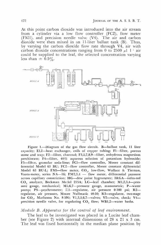
Air from the laboratory air line was passed through a series of filters to remove oil , liyuid water, and particulate matter (FI and F2), water vapor (F3 and F6), and carbon dioxide (F4 and F5) (Figure 1). The air flow was maintained at a constant rate by using a pressure regulator (R2) which supplied air at a constant pressure to a flow controller (FCr) which in turn maintained a constant pressure difference across a needle valve (V3) irrespective of variations in the downstream pressure.
1 Department of So ils and Plant N Ulrition , University of California , Berkeley , California 94720.
472 JOURNAL OF THE A. S. S. B. T.
At this point carbon dioxide was introduced into the air stream from a cylinder via a low flow controller (Fe2), flow meter (FMI), and precision needle valve (V4). The air and carbon dioxide were then mixed in <:in II-liter ballast tank (B). Thus, by varying the carbon dioxide fiow rate through V4, air with carbon dioxide concentrations ranging from 0 to 2500 p.I 1 I air could be supplied to the leaf, the selected concentration varying less than ± 0.5%.
t.fODlJ!..E A
MODULE B
Figure I.-Diagram of the gas flow circuit. B-ballast tank, II liter capacity; El,2-heat exchanger, coils of copper tubing; Fl-filter, porous stone and trap; F2-filter, charcoal; F3,S,7,8,9-filter, anhydrous magnesium perchlorate; F4-filter, 40% aqueous solution of potassium hydroxide; F5-£ill~r, granular soda·lime; rCI-flow controller, Moore constant differential Model 63 BD; FC2-£low controller, Moore constant <4£ferential Model 63 BU·L; FMl-flow meter, CO2 , low·flow, Wallace & Tiernan, Varea·meter, series NA-16; FM2,3,4 - flow meter, differential pr,essure across capillary constriction; HG-dew point hygrometer; IRGA-infra-red CO2 analy:uer, Beckman Mo:iel 215A; LC-Ieaf chamber; MI ,2,3,4-pressure gauge, mechanical; M 5,6,7-pressur,e gauge, manometric; P-water pump; PS-psychrometer; D.. l-regulator, air pressure 0·100 psi; R2regulator, air pressure, Moore Nullmatic 10·30; R3-regulator, two·stage for CO2, Matheson 1'.'0. g·59<t; VI,3,5,6,7-valves; V2-valve, check; V4precision n.eedle valve, for regulating CO2 flow; "VB1,2-water baths.
Module B. Apparatus for the control of leaf enviTonment. The leaf to be investigated was placed in a Lucite leaf cham
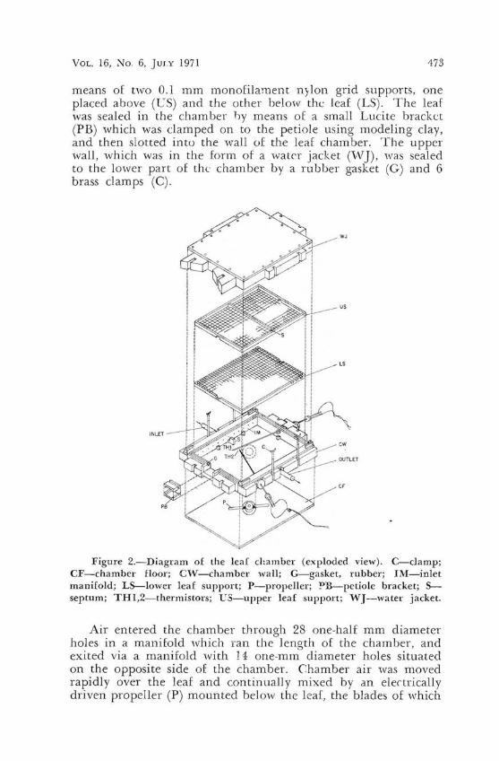
ber (see Figure 2) with internal dimensions of 28 x 21 x 3 cm. The leaf was fixed horizontally in the median plane position by
173 VOL. 16, No.6, Jury 1971
means of two 0.1 mm monofilament nylon grid supports, one placed above (CS) and the other below the leaf (LS). The leaf was sealed in the chamber by means of a small Lucite bracket (PB) which was clamped on to the petiole using modeling clay, and then slotted intu the wall of the leaf chamber. The upper wall, which was in the form of a water jacket (''''J), was sealed to the lower part of the chamber by a rubbeT gasket (G) and 6 brass clamps (C).
Figure 2.-Diagram of the leaf chamber (exploded view). C-clamp; CF-chamber floor; C'V-chamber wall; G-gasket, rubber; }l\'I-inlet manifold; LS---Iower leaf support; P-propeller; ~B-petiole bracket; sseptum; THl,2-thermistors; VS-upper leaf support; WJ-water jacket.
Air entered the chamber through 28 one-half mm diameter holes in a manifold which ran the length of the chamber, and exited via a manifold with ] 4 one-mm diameter holes situated on the opposite side of the chamber. Chamber air 'was moved rapidly over the leaf and continually mixed by an electrically driven propeller (P) mounted below the leaf, the blades of which
474 J OURNAL OF THE A. S. S. B. T.
were perpendicular to the plane or rotation. In order to prevent air from being circulated m ainly in the plane of propeller rotation, a septum (S) was positioned across the cen ter of the chamber so tha t air was forced to move up over the leaf.
The temperature oj' the irradiated leaf, w hich depended on the amount of radiant energy impinging on it and the extent of dissipation of this energy by transpiration, convection and re-radiation , could be maintained within ± O.SOC of the desired leaf temperature by circulating water of constant temperature from vVBl through VV] (inside depth 2 cm). The water supply to v\] was also introduced via manifolds similar to those for air but 'with 12 one-mm holes for entry and 6 two-mm holes for exit. The incoming air to the leaf chamber was also brought to the tern perature of "VB 1 by passage through a heat exchanger (El ).
Two thermistors, TIl , (Yellow Springs Instruments Co., Precision Thermistor Probe, No. 44105) were mounted in supporting steel conduits with th e thermistor bead on a plastic·stiffened wire protruding 4 mm from the end of the conduit. Each conduit was inserted into the leaf chamber through two rubber O-rings inside the ball of a ball joint which permitted the thermistors to be inserted or withdrawn to a varying degTee and rotated to the desired posi tion. Leaf temperature was measured by pressing the thermistors at various points against the surface of the leaf.
The accuracy of the two thermistors in determining leaf tem perature was checked by means of a Barnes infra-red field thermometer (;-Jo . PRT-IOL). Measuremen ts by these two methods were essentiall y in agreement, g iven the precision of the Barnes thermometer (± 0.2 ' C). Temperature variations of up to O.soC were found at different points on the surface of the leaf, and up to 0.2 ' (; difference between the upper and lower surfaces of the leaf. .
The ambient gas (i.e. carbon dioxide or water vapor) concentration in the leaf chamber was determined by the rate of air flow throu gh the chamber, the gas concentration of the inlet air, the extent of turbulent mixing of air 1vithin the chamber and the gas exchange ac tivity of the leaf. Because of the vigorous st irring o( the fan the gas, carbon dioxide or water vapor, concentration of the ou tlet air was assumed to be the ambient value. The concentration of water vapor in the inlet air was very low sin ce the air was dried by passage through F6 and F7 but by adj usting the rate of flow of air through the leaf chamber it was possible to maintain the ambient relative humidity at about 85 % using the water vapor emiw~d by the transpiring leaf.

VOL. 16, No.6, JULY 1971 475
/vlodule C. Apparatus tor the meaS1lrf'ment of water vapor pressure and cm'bon dioxide concentration.
The water vapor pressure of the a ir entering the leaf chamber, e" and leaving the chamber, ey , was estimated using a Dew Point Hygrometer, He;. (Cambridge Systems, Model No. 880) , and a psychrometer, PS, respectively. The latter was similar to that described by Slatyer and Bierhuizen (3)", the difference being in the use of thermistors as temperature sensors rather than thermocouples. Part of the outlet air stream from the chamber 'was passed through heat exchanger E2 in vVB2 to bring the air to temperature, T, before entry into the psychrometer. Air flow ra~e through the psychrometer was usually maintained at 2 I I mIn.
Calculation of transpiration rate was carried out in the following way. The psychrometric equation can be written as
ew - e = A(T - Tw) [I] where T is the temperature of the air entering the psychrometer (equal to the \ 'VB2 temperature); T w , the wet bulb temperature; ew, the saturation vapor pressure at T "' ; e, the vapor pressure at TOC; and A, the psychrometric constant having the value of 0.5 mm of mercury per degree C. The wet bulb temperature of the outlet air streams, T w , was obtained by direct measurement (the psychrometer wet bulb tenperature range being 1540°C) while the saturation vapor pressure at T,<, i.e . ew , was obtained from the Handbook of Chemistry and Physics (2) . Rearranging equation [lJ and applying it to our system to obtain the vapor pressure in the leaf chamber, we have
ey = (ew +- ATw) - AT [2J A graph of (ew +- A Tw) as a function of Tw was prepared so that the calculation of e). from equation [2J could he expedited. The vapor pressure of the inlet air stream, e" was obtained from determination of the dew point, and ~e, i.e. e) - ex> determined. Transpiration rate was therefore (~eleT) pF, where e'r" was the saturation vapor pressure at T OC ; p, the density of water vapor in saturated air at T~ C; and F , the air flow rate through the leaf chamber.
The two air streams leaving HG and PS passed through flow meters FVI4 and F\13, respectively, and were dried by passage through anhydrous magnesium perchlorate (F9 and F8) before entry into the infra-red carbon dioxide analyzer, IRGA, for determination of the difference in carbon dioxide concentrations between the inlet and outlet airstreams. The analyzer detected carbon dioxide differen tial concentrations in the range o to 100 f.d 1-1 with an accuracy of == 1%. Calibration curves
'Numbers in parentheses refer to literatu re cited.

476 JOURNAL OF THE A. S. S. B. T.
for the analyzer were obtained from bottled air-C02 mixtures of known concentration obtained from Matheson Chemical Co.
lVleasurement of air flow rate. The flow meters used for the measurement of air flow rate
in Modules Band C determined the pressure drop (t..P ) across a short length (about 1 cm) of capillary tubing. The flow meters were calibrated 'with a Wet Test Meter (Precision Scientific Co .) over a range of pressures at constant temperature. Flow rate was related to the pressure drop across the capillary, but not proportionall) so in the range ot flow rates used , a result probably indicating the transition from laminar to turbulent flow through the capillaries.
At the flow rates used, the data were described by F =
C(t..P)~, where F is the flow rate (l/min at STP), t..P is the pressure drop across the capillary constriction, and C is a constant depending on the average pressure at the meter. Thus, logarithmic plots of F against t..P were linear and facilitated. interpolation.
The flow meters 'were arranged in the gas circuit so that the air flow through the leaf chamber was given by the difference in flow rates measured by FM2 and FM4.
Control and measurement of inadiance. The leaf was irrad.iated by means of a 1000-W quartz-iodine
incandescent lamp (Berkey Colortran No. LQKIO/DY) fitted with a filter to reduce the infra-red heat load on the leaf. The lamp was mounted on a frame which could be raised or lowered in relation to the leaf surface to pro\ ide a range of irradiances. The spectral intensity and the radiant flux density impinging on the leaf in the chamber 'were measured using a spectroradiometer (Instrumentation Specialties Co. , Inc., "fodel SR) (Figure 3). The radiant flux density at the leaf surface was obtained by integrating the area under the curves between 380 and 15:>0 m,u. and between 100 and 700 m,u. , giving \alues of 32.7 and 23 .6 mWcm-2
, respectivdy. The radiant flux density transmitted through a sugar beet leaf placed between the radiometer and the lamp under the same conditions was 4.22 mvVcrn-2 (380-1550 m,u.), and 1.07 mWcm-2 (400-700 m,u.). The luminous flux density measured with a Weston cell at the position of the radiometer when the water-jacketed chamber cover was between the lamp and the instrument was 6500 foot-candles. Thus, the relation between energy units and photometric units was
23.6 mvVcm-2
6.5 x 103 ft-c = 36.3 x 10- ' mvVcm-2/ft-c
a ratio comparable to that given by Gaastra for combined filament high-pressure mercury vapor lamps (Gaastra (1), see Table

VOL. 16, No.6, JULY 1971
IV, HPL and ML). The radiation spectrum should remain essentially unchanged when the lamp is raised to decrease the radiant flux density so that under such conditions photocell measurements can be converted to radiant flux density by using this factor.
1000 1200 1400
Wo v e leng lh , >..(mll-)
Figure 3.-The relation of spectl'al intensity (HA) with wave-length (A) of the light source obtained by placing a spectroradiometer in the position of the leaf (solid line), and beneath the leaf (dotted line)_ The leaf was normally positioned 50 em from the lamp with the glass heat filter and water-filled chamber cover between the lamp and the leaf.
Output handling and display. The outputs from the thermistors measuring the tempera
tures of the leaf, vvater baths and psychrometer wet bulb, and the output from the carbon dioxide analyzer were sequentially displayed on a potentiometric recorder (IIeathkit Servo-recorder, EUQ-20A) by means o[ a custom-built fully transistorised automatic switch.
Summary An apparatus is described which measures the rates of the
carbon dioxide and water vapor exchange of attached sugarbeet leaves in a controlled environment. Leaves were enclosed in a chamber and the gas exchange determined using an open flow circuit. Carbon dioxide concentration was determined bv infra-red gas analyzer, and water vapor concentration by dev;r point hygrometer and thermistor psychrometer.
Acknowledgements The authors gratefully acknowledge the suggestions and me
ticulous technical assistance of Clyde Brown in the construction of this apparatus . This work was supported by the Agricultural Research Service, U .S. Department of Agriculture, under cooperative agreement No. 12-14-100-9754 (34) administered by the Plant Science Division, Beltsville, Ylaryland.
478 JOURNAL OF THE S. S. B. T.
Literature Cited
(I) GAASTRA, P. 1959. of crop plants as influenced by tcmpCLlture, and stomatal diffusion resist
59 : ]·68. (2) HODGMAN, ]Vl. SELBY. 1962. Handbook of
and Rubber Ohio.
(3) R. O. and J. F. BlERHCIZE!'I. 1964. Differential for continuous measurements of transpiration. Plant 1051-1056.