an analytical algorithm to determine...
TRANSCRIPT

Klimenta, D. O., et al.: An Analytical Algorithm to Determine Allowable … THERMAL SCIENCE, Year 2016, Vol. 20, No. 2, pp. 717-730 717
AN ANALYTICAL ALGORITHM TO DETERMINE ALLOWABLE AMPACITIES OF HORIZONTALLY INSTALLED
RECTANGULAR BUS BARS
by
Dardan O. KLIMENTA*, Bojan D. PEROVIĆ, Miroljub D. JEVTIĆ, and Jordan N. RADOSAVLJEVIĆ
Faculty of Technical Sciences, University of Priština in Kosovska Mitrovica, Kosovska Mitrovica, Serbia
Original scientific paper DOI: 10.2298/TSCI140829127K
The main objective of this paper is to propose an algorithm for the determination of the allowable ampacities of single rectangular-section bus bars without the occurrence of correction factors. Without correction factors, the ampacity com-putation of the copper and aluminum bus bars is fully automatized. The analyti-cal algorithm has been implemented in a computer program code that along with the allowable ampacity can compute the bus bar temperature and the individual heat transfer coefficient for each side of the bus bar, as well as their correspond-ing power losses. Natural and forced convection correlations for rectangular bus bars are applied. Effects of the solar radiation and radiation heat losses from the bus bar surface are taken into consideration as well. The finite element method has been used for the linear/non-linear steady-state thermal analysis, i. e. for val-idation of the analytical algorithm. All finite element method based numerical computations were carried out using the COMSOL heat transfer module. Key words: allowable ampacity, analytical algorithm, bus bar,
empirical correlations, heat transfer
Introduction
In electrical power substations, bus bars connect a number of incoming circuit con-nections to a number of out coming circuit connections. Bus bars are made of non-insulated solid, hollow and profiled copper or aluminum conductors. Conductors with circular and rec-tangular cross-sections or U-shaped conductors are used in electrical power substations for rated voltages up to 35 kV, whilst stranded or tubular conductors are used in electrical power substations for rated voltages equal to or higher than 110 kV. The selection of a bus bar cross--section is carried out: (a) with regard to the Iop current under normal operating conditions – thermal stress that the conductor can withstand continuously, (b) with regard to the conven-tional value of the short-time withstand current during a three-phase short-circuit – thermal stress that the conductor can withstand in a short period of time, and (c) with regard to me-chanical stresses during a three-phase short-circuit.
The allowable ampacity of the bus bar, Icp, is determined based on the balance be-tween the amount of heat generated within the bus bar material (Joule's losses) and the
–––––––––––––– * Corresponding author; e-mail: [email protected]
Klimenta, D. O., et al.: An Analytical Algorithm to Determine Allowable … 718 THERMAL SCIENCE, Year 2016, Vol. 20, No. 2, pp. 717-730
amount of heat reaching the outer surface of the bus bar (solar radiation) on the one, and the amount of heat conducted away from the bus bar (heat losses due to the convection and radia-tion on the outer surface of the bus bar) on the other hand. When selecting a cross-section of a bus bar, its allowable ampacity, Icp, must be larger than the operating current, Iop. According to standards, the difference between the tabulated continuously permissible temperature of the bus bar, TcpT, (65 or 70 °C) and the tabulated temperature of the surrounding air, TaT, (35 or 40 °C) accounts to 30 °C regardless of the material type from which the bus bar is made.
Moreover, the allowable ampacity should be distinguished from the rated current of the bus bar, Inom. The Icp obtained by recomputation of the rated current to actual conditions at the location foreseen for the bus bur installation, i. e. by means of expression: Icp = C1 C2 C3 C4 C5 Inom, where C1-C5 are appropriate correction factors [1, 2].
Within the classical procedure for selecting the bus bar cross-sections, continuously permissible temperature of the bus bar, Tcp, appears along with the tabulated continuously per-missible temperature of the bus bar, TcpT [1, 2]. However, the aforementioned is a deviation from the well-established rule to use only one, in this particular case, tabulated value of its con-tinuously permissible temperature when computing the allowable ampacity of a conductor.
Therefore, this paper presents a procedure for the determination of the allowable am-pacity of a bus bar using the tabulated continuously permissible temperature without the occur-rence of correction factors C1-C5. The allowable ampacity of a bus bar depends on the shape and dimensions of its cross-section, as well as on the number of conductors and their arrange-ment in the package of one phase, distances between the packages of phase conductors, resistiv-ity of the bus bar material, colour and physical properties of the outer surface of the bus bar (emission and absorption coefficients), ambient conditions (solar irradiance, ambient air tem-perature, wind velocity, vw, and wind direction) and thermo-physical properties of air.
Factors on which the allowable ampacity of a bus bar depend are modelled by corre-sponding convective (either natural or forced one) and radiation boundary conditions, as well as heat sources located inside and outside of the bus bar material [3-5]. A MATLAB pro-gramme entitled BUSBAR.m, which is based on a set of empirical correlations similar to the one in [3], has been developed and used in order to compute the allowable ampacity of the bus bar, its temperature and individual heat transfer coefficient for each side of the bus bar, as well as their corresponding losses.
Governing equation
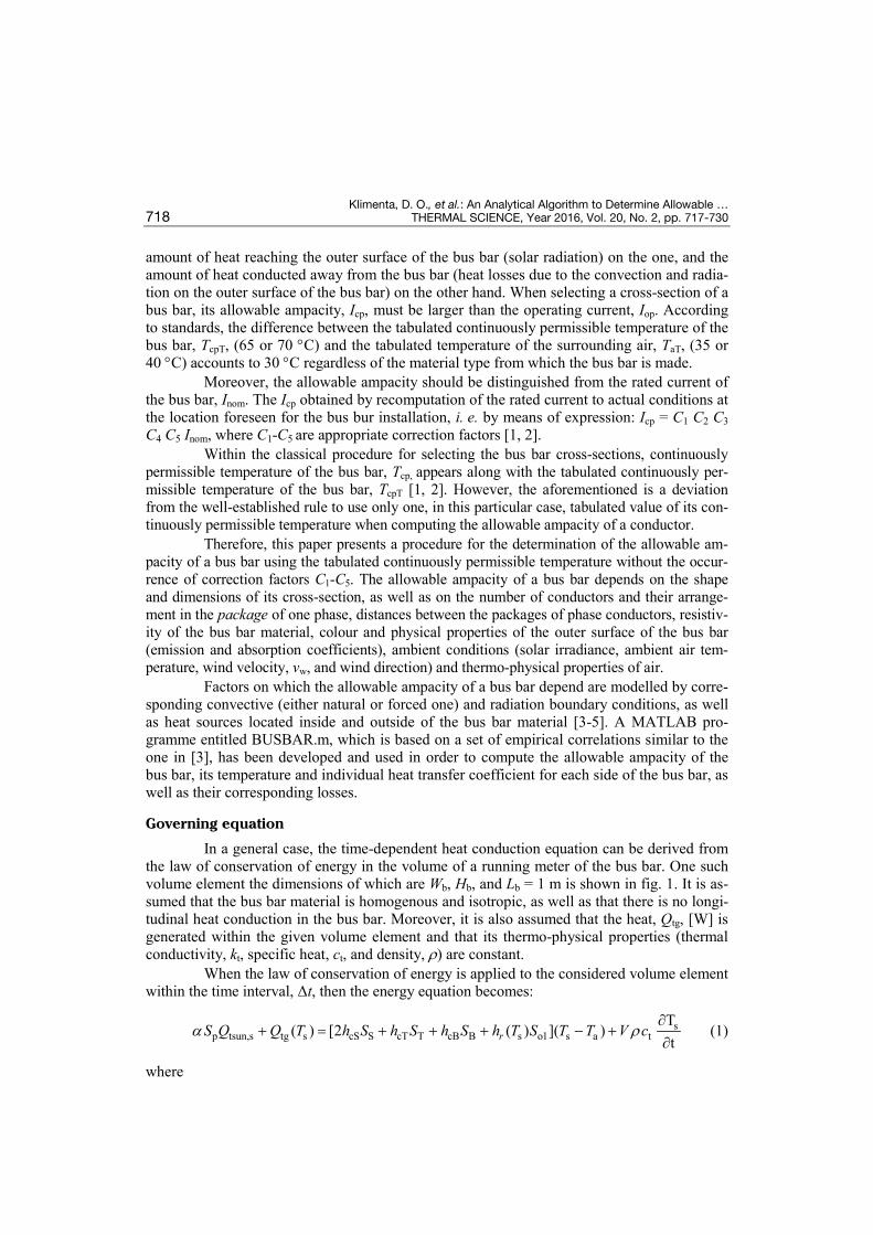
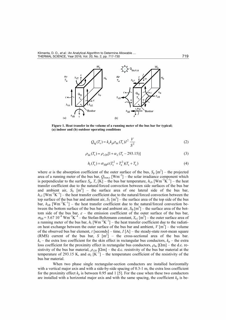
In a general case, the time-dependent heat conduction equation can be derived from the law of conservation of energy in the volume of a running meter of the bus bar. One such volume element the dimensions of which are Wb, Hb, and Lb = 1 m is shown in fig. 1. It is as-sumed that the bus bar material is homogenous and isotropic, as well as that there is no longi-tudinal heat conduction in the bus bar. Moreover, it is also assumed that the heat, Qtg, [W] is generated within the given volume element and that its thermo-physical properties (thermal conductivity, kt, specific heat, ct, and density, r) are constant.
When the law of conservation of energy is applied to the considered volume element within the time interval, Δt, then the energy equation becomes:
sp tsun,s tg s cS S cT T cB B s o1 s a t
T( ) [2 ( ) ]( )
trS Q Q T h S h S h S h T S T T V ca r∂
+ = + + + − +∂
(1)
where
Klimenta, D. O., et al.: An Analytical Algorithm to Determine Allowable … THERMAL SCIENCE, Year 2016, Vol. 20, No. 2, pp. 717-730 719
Figure 1. Heat transfer in the volume of a running meter of the bus bar for typical; (a) indoor and (b) outdoor operating conditions
2tg s s p dc s 2( ) ( ) VQ T k k T I
Sr= (2)
dc s 20 s( ) [1 ( 293.15)]e LT Tr r a= + − (3)
2 2
r s SB s a s a( ) ( )( )h T T T T Ts ε= + + (4)
where a is the absorption coefficient of the outer surface of the bus, Sp [m2] – the projected area of a running meter of the bus bar, Qtsun,s [Wm–2] – the solar irradiance component which is perpendicular to the surface Sp, Ts [K] – the bus bar temperature, hcS [Wm–2K–1] – the heat transfer coefficient due to the natural/forced convection between side surfaces of the bus bar and ambient air, SS [m2] – the surface area of one lateral side of the bus bar, hcT [Wm–2K–1] – the heat transfer coefficient due to the natural/forced convection between the top surface of the bus bar and ambient air, ST [m2] – the surface area of the top side of the bus bar, hcB [Wm–2K–1] – the heat transfer coefficient due to the natural/forced convection be-tween the bottom surface of the bus bar and ambient air, SB [m2] – the surface area of the bot-tom side of the bus bar, ε – the emission coefficient of the outer surface of the bus bar, sSB = 5.67 10–8 Wm–2K–4 – the Stefan-Boltzmann constant, So1 [m2] – the outer surface area of a running meter of the bus bar, hr [Wm–2K–1] – the heat transfer coefficient due to the radiati-on heat exchange between the outer surface of the bus bar and ambient, V [m3] – the volume of the observed bus bar element, t [seconds] – time, I [A] – the steady-state root-mean square (RMS) current of the bus bar, S [m2] – the cross-sectional area of the bus bar. ks – the extra loss coefficient for the skin effect in rectangular bus conductors, kp – the extra loss coefficient for the proximity effect in rectangular bus conductors, rdc [Ωm] – the d.c. re-sistivity of the bus bar material, re20 [Ωm] – the d.c. resistivity of the bus bar material at the temperature of 293.15 K, and aL [K–1] – the temperature coefficient of the resistivity of the bus bar material.
When two phase single rectangular-section conductors are installed horizontally with a vertical major axis and with a side-by-side spacing of 0.3-1 m, the extra loss coefficient for the proximity effect kp is between 0.95 and 1 [5]. For the case when these two conductors are installed with a horizontal major axis and with the same spacing, the coefficient kp is be-
Klimenta, D. O., et al.: An Analytical Algorithm to Determine Allowable … 720 THERMAL SCIENCE, Year 2016, Vol. 20, No. 2, pp. 717-730
tween 1 and 1.05 [5]. In the case of indoor installation these side-by-side spacings are usually larger than 0.3 m. Therefore, it can be assumed that the proximity effect is negligible (kp ≈ 1). Furthermore, electrodynamic forces between two phase conductors are proportional to the current square. For rated currents these electrodynamic forces have small magnitudes and they are therefore not discussed.
For the steady-state heat transfer (∂Ts/∂t = 0), the bus bar temperature that is equal to TcpT and a maximum amount of solar heat that can be absorbed by the outer surface of a run-ning meter of the bus bar (QtsunM = a SpM Qtsun,s), eq. (1) becomes:
pM tsun,s tg cpT cS S cT T B B r cpT o1 cpT a( ) [2 ( ) ]( )cS Q Q T h S h S h S h T S T Ta + = + + + − (5)
where SpM [m2] is the maximum projected area of a running meter of the bus bar. Therefore, the expression for I can be expressed from eq. (5):
1/2cS S cT T cB B r cpT o1 cpT a pM tsun,s
1/2s p dc cpT
[2 ( ) ]( )
[ ( ) ]
h S h S h S h T S T T S Q SI
k k T V
a
r
+ + + − −= (6)
where rdc(TcpT) and hr(TcpT) should be computed by means of eqs. (3) and (4). According to eq. (1), for the steady-state heat transfer and QtsunM = aSpMQtsun,s, the
unknown bus bar temperature, Ts, is:
pM tsun,s tg ss a
cS S cT T cB B r s o1
( )2 ( )
S Q Q TT T
h S h S h S h T Sa +
= ++ + +
(7)
For indoor installations, the allowable ampacities that correspond to central Europe-an conditions are determined under the following assumptions [1-3]: (a) that the ambient air is still; (b) that the surfaces of bare conductors are partly oxidized giving an emission coefficient of ε = 0.40 – for Cu conductors and ε = 0.35 – for Al conductors; or (c) that the surfaces of conductors are painted giving an emission coefficient of approximately ε = 0.90.
Furthermore, for outdoor installations, the allowable ampacities that correspond to central European conditions are determined under the following assumptions [1-3]: (a) that the ambient air moves slightly, i. e. that the wind velocity is vw = 0.6 m/s; (b) that the solar ir-radiance is Qtsun,s = 1000 W/m2; (c) that the surfaces of bare conductors are normally oxidized giving an emission coefficient of ε = 0.60 – for Cu conductors and ε = 0.50 – for Al conduc-tors, as well as an absorption coefficient of a = 0.45 – for Cu conductors and a = 0.35 – for Al conductors; or (d) that the surfaces of conductors are painted giving an emission coeffi-cient of approximately ε = 0.90 and an absorption coefficient of a = 0.70.
Analytical algorithm
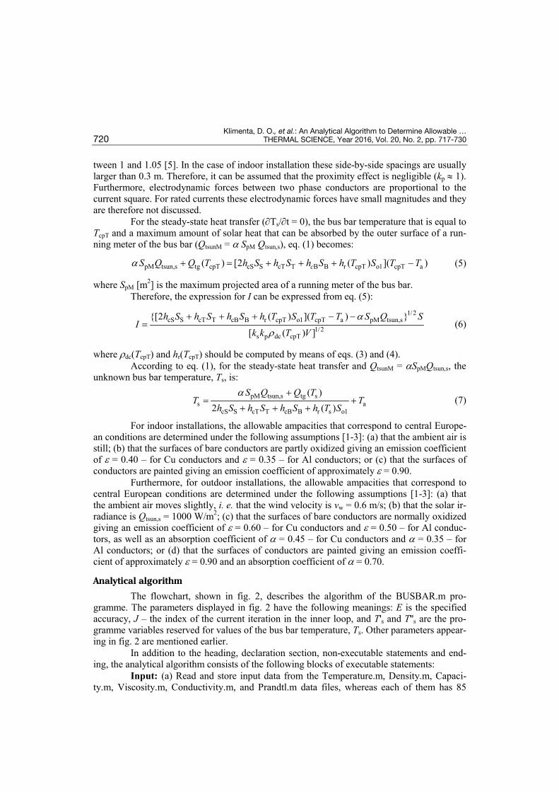
The flowchart, shown in fig. 2, describes the algorithm of the BUSBAR.m pro-gramme. The parameters displayed in fig. 2 have the following meanings: E is the specified accuracy, J – the index of the current iteration in the inner loop, and T's and T''s are the pro-gramme variables reserved for values of the bus bar temperature, Ts. Other parameters appear-ing in fig. 2 are mentioned earlier.
In addition to the heading, declaration section, non-executable statements and end-ing, the analytical algorithm consists of the following blocks of executable statements:
Input: (a) Read and store input data from the Temperature.m, Density.m, Capaci-ty.m, Viscosity.m, Conductivity.m, and Prandtl.m data files, whereas each of them has 85
Klimenta, D. O., et al.: An Analytical Algorithm to Determine Allowable … THERMAL SCIENCE, Year 2016, Vol. 20, No. 2, pp. 717-730 721
Figure 2. The flowchart illustrating the algorithm of the BUSBAR.m programme
discrete values taken from [5], i. e. values of temperature, density, specific heat, dynamic vis-cosity, thermal conductivity, and Prandtl number for air; (b) select the type of convection: 1 – for the natural or 2 – for the forced convection; (c) if the natural convection is selected, then the following should be selected: 1 – for Ts > Ta or 2 – for Ts < Ta; (d) if the forced convection is selected, then the following should be selected: 1 – for the case when the wind direction is perpendicular to the longitudinal axis of the bus bar or 2 – for the case when the wind direc-tion is parallel to the longitudinal axis of the bus bar; (e) enter the value for the following: Wb [m], Hb [m], I = Inom [A], TcpT [K], re20 [Ωm], aL [K–1], ks [–], kp [–], Ta [K], vw [ms–1], ε [–], a [–], and Qtsun,s [Wm–2]; (f) for an initial estimate of Ts, for all unknown heat transfer coefficients enter the same numerical value h'c [Wm–2K–1] which corresponds to the upper bound of natural/forced convection in the gases.
1st set of statements: (a) compute the value for the following: S = WbHb, V = S1 = S, SS = Hb 1 = Hb, ST = Wb 1 = Wb, SB = Wb 1 = Wb, So1 = 2SS + ST + SB, (b) compute the diagonal of the bus bar cross-section DH as: DH = (Wb
2 + Hb2)1/2; (c) compute the maxi-
mum projected area of a running meter of the bus bar SpM as: SpM = DH 1; (d) compute d.c. re-sistivity of the bus bar material at the temperature TcpT as: rdc(TcpT) = re20 [1 + aL (TcpT – – 293.15)]; (e) compute the value for QtsunM as: QtsunM = aSpM Qtsun,s.
1st condition: start iterations in the outer loop and repeat the commands in the loop until the absolute value of (T''s – TcpT) becomes lower than the specified accuracy, E = 0.2.
Assignment: assign the value 0 to the index of the current iteration J in the inner loop.

Klimenta, D. O., et al.: An Analytical Algorithm to Determine Allowable … 722 THERMAL SCIENCE, Year 2016, Vol. 20, No. 2, pp. 717-730
2nd set of statements: (a) compute the volume power of heat sources located in the bus bar material Qtg,v as: Qtg,v = kskprdc(TcpT)(I/S)2; (b) compute the value for Qtg as: Qtg = Qtg,vV; (c) assign the value h'c to the first variable h'cS reserved for the coefficient hcS; (d) assign the value h'c to the first variable h'cT reserved for the coefficient hcT; (e) assign the value h'c to the first variable h'cB reserved for the coefficient hcB; (f) assign the value h'c to the first variable h'r reserved for the coefficient hr; (g) estimate the bus bar temperature based on the computed values for Qtg, QtsunM, SS, ST, SB, and So1, and the entered values for h'c and Ta as: T's = (Qtg + QtsunM)/[h'c(2SS + ST + SB + So1)] + Ta; (h) assign the value 0 to the variable re-served for the bus bar temperature Ts.
2nd condition: start iterations in the inner loop and repeat the commands in the loop until the absolute value of (T's – Ts) becomes lower than the specified accuracy, E = 0.2.
3rd set of statements: if the value of the variable Ts differs from 0, then: (a) assign the value of the 2nd variable reserved for the same convection coefficient h''cS to the variable h'cS; (b) assign the value of the 2nd variable reserved for the same convection coefficient h''cT to the variable h'cT; (c) assign the value of the 2nd variable reserved for the same convection coefficient h''cB to the variable h'cB; (d) assign the value of the 2nd variable reserved for the same heat transfer coefficient due to the radiation h''r to the variable h'r; (e) assign the value of the variable Ts to the variable T's.
4th set of statements: (a) compute the film temperature, Tfilm, as [4, 5]: Tfilm = (T's + + Ta)/2; (b) compute the thermal expansion coefficient of air, b, as [4, 5]: b = 1/Tfilm; (c) call to the subroutine CSCURVE, which approximates the temperature dependence of the density, specific heat, dynamic viscosity, thermal conductivity, and Prandtl number for air by means of cubic spline interpolation and arrays of discrete values from the pair of input data files: Temperature.m-Density.m, Temperature.m-Capacity.m, Temperature.m-Viscosity.m, Tem-perature.m-Conductivity.m, and Temperature.m-Prandtl.m, respectively; which also assigns the value of density, specific heat, dynamic viscosity, thermal conductivity, and Prandtl num-ber for air to the following variables: r, ct, µ, kt, and Pr at Tfilm, respectively; (d) compute the kinematic viscosity of air, ν, as: ν = µ/r.
5th set of statements: if the natural convection heat transfer is considered, then: (a) for the lateral sides of the bus bar, the following equations are valid [6]:
3s a b
S 29.81 ( ' )
GrT T Hbν−
= (8)
2
1/6S
S 8/279/16
0.387(Gr Pr)Nu 0.825
0.4921Pr
= +
+
for 2SGr Pr 10≤ (9)
1/4S
S 4/299/16
0.67(Gr Pr)Nu 0.68
0.4921Pr
= + +
for 2SGr Pr 10> (10)

Klimenta, D. O., et al.: An Analytical Algorithm to Determine Allowable … THERMAL SCIENCE, Year 2016, Vol. 20, No. 2, pp. 717-730 723
tcS S
bcS
' Nu''
2
khHh
+= (11)
where GrS and NuS are corresponding Grashof and Nusselt numbers, respectively; (b) for the top side of the bus bar, the following equations are valid [5, 7, 8]:
3
s a bT 2
9.81 ( ' )Gr
T T Wbν−
= (12)
1/4
T TNu 0.54(Gr Pr)= for s aT T> and 6T
.Gr Pr 8 10≤ (13)
1/3
T TNu 0.15(Gr Pr)= for s aT T> and 6T
.Gr Pr 8 10> (14)
1/4
T TNu 0.27(Gr Pr)= for s aT T< (15)
tcT T
bcT
' Nu''
2
khWh
+= (16)
where GrT and NuT are corresponding Grashof and Nusselt numbers, respectively; (c) for the bottom side of the bus bar, the following equations are valid [5, 7, 8]:
3
s a bB 2
9.81 ( ' )Gr
T T Wbν−
= (17)
1/4
B BNu 0.54(Gr Pr)= for s aT T< and 6B
.Gr Pr 8 10≤ (18)
1/3
B BNu 0.15(Gr Pr)= for s aT T< and 6B
.Gr Pr 8 10> (19)
1/4
B BNu 0.27(Gr Pr)= for s aT T> (20)
tcB B
bcB
' Nu''
2
khWh
+= (21)
where GrB and NuB are corresponding Grashof and Nusselt numbers, respectively. 6th set of statements: if the forced convection heat transfer is considered, then:
(a) for the lateral sides of the bus bar, the following equations are valid [5, 7, 9, 10]:
w bSRe
v Hν
= (22)
0.731 1/3S SNu 0.205 Re Pr= for the wind direction ⊥ to the bus bar axis (23)
1/2 1/3S SNu 0.664 Re Pr= for the wind direction || to the bus bar axis (24)
tcS S
bcS
' Nu''
2
khHh
+= (25)
where ReS and NuS are corresponding Reynolds and Nusselt numbers, respectively; (b) for the top and bottom sides of the bus bar and both directions of the wind with regard to the longitu-dinal axis of the bus bar, the following equations are valid [5, 6, 10]:
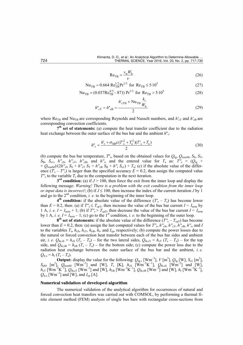
Klimenta, D. O., et al.: An Analytical Algorithm to Determine Allowable … 724 THERMAL SCIENCE, Year 2016, Vol. 20, No. 2, pp. 717-730
w bTBRe
v Wν
= (26)
1/2 1/3TB TBNu 0.664 Re Pr= for 5
TBRe 5 10≤ ⋅ (27) 4/5 1/3
TB TBNu (0.037Re 871) Pr= − for 5TBRe 5 10> ⋅ (28)
tcTB TB
bcT cB
' Nu'' ''
2
khWh h
+= = (29)
where ReTB and NuTB are corresponding Reynolds and Nusselt numbers, and h'cT and h'cB are corresponding convection coefficients.
7th set of statements: (a) compute the heat transfer coefficient due to the radiation heat exchange between the outer surface of the bus bar and the ambient h''r:
2 2r SB s a s a
r' ( ' )( ' )
''2
h T T T Ths ε+ + +
= (30)
(b) compute the bus bar temperature, T''s, based on the obtained values for Qtg, QtsunM, SS, ST, SB, So1, h''cS, h''cT, h''cB, and h''r, and the entered value for Ta as: T''s = (Qtg + + QtsunM)/(2h''cS SS + h''cT ST + h''cB SB + h''r So1) + Ta; (c) if the absolute value of the differ-ence (T's – T''s) is larger than the specified accuracy E = 0.2, then assign the computed value T''s to the variable Ts due to the computation in the next iteration.
3rd condition: (a) if J > 100, then force the exit from the inner loop and display the following message: Warning! There is a problem with the exit condition from the inner loop or input data is incorrect!; (b) if J ≤ 100, then increase the index of the current iteration J by 1 and go to the 2nd condition, i. e. to the beginning of the inner loop.
4th condition: if the absolute value of the difference (T's – Ts) has become lower than E = 0.2, then: (a) if T''s ≤ TcpT, then increase the value of the bus bar current I = Inom by 1 A, i. e. I = Inom + 1; (b) if T''s > TcpT, then decrease the value of the bus bar current I = Inom by 1 A, i. e. I = Inom – 1; (c) go to the 1st condition, i. e. to the beginning of the outer loop.
8th set of statements: if the absolute value of the difference (T''s – TcpT) has become lower than E = 0.2, then: (a) assign the last computed values for T''s, h''cS, h''cT, h''cB, h''r, and I to the variables Ts, hcS, hcT, hcB, hr, and Icp, respectively; (b) compute the power losses due to the natural or forced convection heat transfer between each of the bus bar sides and ambient air, i. e. Qth,sS = hcS (Ts – Ta) – for the two lateral sides, Qth,sT = hcT (Ts – Ta) – for the top side, and Qth,sB = hcB (Ts – Ta) – for the bottom side; (c) compute the power loss due to the radiation heat exchange between the outer surface of the bus bar and the ambient, i. e. Qtr,s = hr (Ts – Ta).
Output: display the value for the following: Qtg,v [Wm–3], V [m3], Qtg [W], So1 [m2], SpM [m2], QtsunM [Wm–2] and [W], Ts [K], hcS [Wm–2K–1], Qth,sS [Wm–2] and [W], hcT [Wm–2K–1], Qth,sT [Wm–2] and [W], hcB [Wm–2K–1], Qth,sB [Wm–2] and [W], hr [Wm–2K–1], Qtr,s [Wm–2] and [W], and Icp [A].
Numerical validation of developed algorithm
The numerical validation of the analytical algorithm for occurrences of natural and forced convection heat transfers was carried out with COMSOL, by performing a thermal fi-nite element method (FEM) analysis of single bus bars with rectangular cross-sections from

Klimenta, D. O., et al.: An Analytical Algorithm to Determine Allowable … THERMAL SCIENCE, Year 2016, Vol. 20, No. 2, pp. 717-730 725
[3]. The results of simulations performed for the case of natural convection are given in tab. 1, whilst tab. 2 shows results of simulations performed for the case of forced convection.
Table 1. Rated currents and allowable ampacities of single rectangular bus bars in the case of indoor installationa
a For aluminum alloy 6101-T61 horizontally installed bus bars, TaT = 40 °C, TcpT = 70 °C, vw = 0 m/s, ε = 0.35, a = 0, and f = 60 Hz; b According to [11], these rated currents were obtained experimentally; c Percentage error: PE = (Icp – Inom) 100/Inom.
Dimensions (Wb i Hb), bus bar currents (rated Inom or assumed Iass) and skin effect coefficients, ks, for the considered bus bars are given in tabs. 1 and 2. The d. c. resistivity of the aluminum alloy 6101-T61 at 20 °C and its corresponding temperature coefficient are re20 = 2.998 10–8 Ω m and aL = 0.00383 K–1 [3], respectively. The coefficients due to the nat-ural and forced convection corresponding to the turbulent flow in the gases are h'c = 12 W/m2K and h'c = 300 W/m2K1, respectively [5]. According to [3], the solar irradiance
Wb Hb 60 Hz ks
at 70 °C
Inom from handbook b
Icp and Tcp
Ref. [3] PE c BUSBAR COMSOL PE c
m/in m/in – A A % A/°C A/°C %
Bus bars installed with a vertical major axis
0.00635 /0.25
0.0508 /2 1.014 545 535 –1.84
545 /69.91
545 /69.92 0
0.00635 /0.25
0.1524 /6 1.092 1381 1374 –0.51
1371 /70.09
1371 /70.11 –0.72
0.009525 /0.375
0.1016 /4 1.100 1191 1178 –1.09
1186 /70.06
1186 /70.08 –0.42
0.009525 /0.375
0.2032 /8 1.210 2098 2108 +4.77
2081 /70.07
2081 /70.11 –0.81
0.0127 /0.5
0.1016 /4 1.140 1369 1356 –0.95
1364 /70.06
1364 /70.08 –0.37
0.0127 /0.5
0.2032 /8 1.259 2393 2407 +0.59
2376 /70.09
2376 /70.13 –0.71
Bus bars installed with a horizontal major axis
0.0508 /2
0.00635 /0.25 1.014 530 534 +0.76
519 /70.01
519 /70.03 –2.08
0.1524 /6
0.00635 /0.25 1.092 1270 1333 +4.96
1287 /69.91
1287 /69.95 +1.34
0.1016 /4
0.009525 /0.375 1.100 1130 1157 +2.39
1125 /70.07
1125 /70.09 –0.44
0.2032 /8
0.009525 /0.375 1.210 1820 2025 +11.26
1993 /69.92
1993 /69.96 +9.5
0.1016 /4
0.0127 /0.5 1.140 1300 1332 +2.46
1299 /70.07
1299 /70.09 –0.08
0.2032 /8
0.0127 /0.5 1.259 2050 2313 +12.83
2279 /69.90
2279 /69.94 +11.17
Klimenta, D. O., et al.: An Analytical Algorithm to Determine Allowable … 726 THERMAL SCIENCE, Year 2016, Vol. 20, No. 2, pp. 717-730
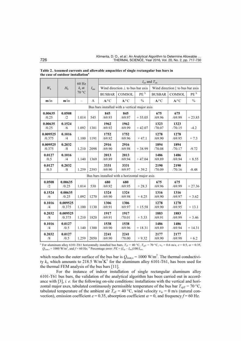
Table 2. Assumed currents and allowable ampacities of single rectangular bus bars in the case of outdoor installationa
a For aluminum alloy 6101-T61 horizontally installed bus bars, TaT = 40 °C, TcpT = 70 °C, vw = 0.6 m/s, ε = 0.5, a = 0.35, Qtsun,s = 1000 W/m2, and f = 60 Hz; b Percentage error: PE = (Icp – Iass)100/Iass.
which reaches the outer surface of the bus bar is Qtsun,s = 1000 W/m2. The thermal conductivi-ty kt, which amounts to 218.5 W/m1K1 for the aluminum alloy 6101-T61, has been used for the thermal FEM analysis of the bus bars [11].
For the instance of indoor installation of single rectangular aluminum alloy 6101-T61 bus bars, the validation of the analytical algorithm has been carried out in accord-ance with [3], i. e. for the following on-site conditions: installations with the vertical and hori-zontal major axes, tabulated continuously permissible temperature of the bus bar TcpT = 70 °C, tabulated temperature of the ambient air TaT = 40 °C, wind velocity vw = 0 m/s (natural con-vection), emission coefficient ε = 0.35, absorption coefficient a = 0, and frequency f = 60 Hz.
Wb Hb 60 Hz ks at
70 °C Iass
Icp and Tcp
Wind direction ⊥ to bus bar axis Wind direction || to bus bar axis
BUSBAR COMSOL PE b BUSBAR COMSOL PE b
m/in m/in – A A/°C A/°C % A/°C A/°C %
Bus bars installed with a vertical major axis
0.00635 /0.25
0.0508 /2 1.014 545
845 /69.93
845 /69.97 + 55.05
675 /69.96
675 /69.99 + 23.85
0.00635 /0.25
0.1524 /6 1.092 1381
1962 /69.92
1962 /69.99 + 42.07
1323 /70.07
1323 /70.15 -4.2
0.009525 /0.375
0.1016 /4 1.100 1191
1752 /69.92
1752 /69.96 + 47.1
1278 /69.90
1278 /69.95 + 7.3
0.009525 /0.375
0.2032 /8 1.210 2098
2916 /69.90
2916 /69.98 + 38.99
1894 /70.08
1894 /70.17 -9.72
0.0127 /0.5
0.1016 /4 1.140 1369
2013 /69.89
2013 /69.94 + 47.04
1486 /69.89
1486 /69.94 + 8.55
0.0127 /0.5
0.2032 /8 1.259 2393
3331 /69.90
3331 /69.97 + 39.2
2190 /70.09
2190 /70.16 -8.48
Bus bars installed with a horizontal major axis
0.0508 /2
0.00635 /0.25 1.014 530
680 /69.92
680 /69.95 + 28.3
675 /69.96
675 /69.99 + 27.36
0.1524 /6
0.00635 /0.25 1.092 1270
1324 /69.90
1324 /69.98 + 4.25
1316 /69.90
1316 /69.97 + 3.62
0.1016 /4
0.009525 /0.375 1.100 1130
1306 /69.91
1306 /69.97 + 15.58
1278 /69.90
1278 /69.95 + 13.1
0.2032 /8
0.009525 /0.375 1.210 1820
1917 /69.91
1917 /70.01 + 5.33
1883 /69.91
1883 /69.99 + 3.46
0.1016 /4
0.0127 /0.5 1.140 1300
1538 /69.90
1538 /69.96 + 18.31
1486 /69.89
1486 /69.94 + 14.31
0.2032 /8
0.0127 /0.5 1.259 2050
2241 /69.90
2241 /70.00 + 9.32
2177 /69.90
2177 /69.98 + 6.2
Klimenta, D. O., et al.: An Analytical Algorithm to Determine Allowable … THERMAL SCIENCE, Year 2016, Vol. 20, No. 2, pp. 717-730 727
For the instance of outdoor installation of single rectangular aluminum alloy 6101-T61 bus bars, the validation of the analytical algorithm has been carried out for the fol-lowing on-site conditions: installations with the vertical and horizontal major axes, tabulated continuously permissible temperature TcpT = 70 °C, tabulated temperature of the ambient air TaT = 40 °C, wind velocity vw = 0.6 m/s (forced convection), emission coefficient ε = 0.5, ab-sorption coefficient a = 0.35, solar irradiance Qtsun,s = 1000 W/m2, and frequency f = 60 Hz.
Values of continuously permissible temperature of bus bars obtained for instances of natural and forced convection heat transfers by means of the BUSBAR.m and COMSOL pro-grammes differ from the temperature TcpT = 70 °C by approximately ±0.2 °C. These differ-ences are negligible and represent a consequence of the specified accuracy E = 0.2 and gener-ation of only integer values for the allowable ampacity Icp.
It should be emphasized that the COMSOL heat transfer module uses as input data some of the output data generated by the BUSBAR.m program. For instance, the bus bar cur-rent cannot be entered directly into COMSOL, but its influence is taken via the volume power of heat sources located in the bus bar material obtained by the BUSBAR.m programme. Moreover, as input data, COMSOL also uses heat transfer coefficients due to the convection generated by means of the BUSBAR.m programme.
Application of developed algorithm
The analytical algorithm, i. e. the BUSBAR.m programme is simple to use and it gen-erates the allowable ampacities of the bus bars in a rather fast manner, as well as other parame-ters necessary for its thermal FEM analysis in COMSOL. The given algorithm/programme is applied easily when extra losses coefficients for the skin effect in the considered bus bars are known and when ambient conditions on the installation site thereof are standardised.
Since copper and aluminum conductors with rectangular cross-sections are used ex-clusively in indoor installations of the rated voltage of which is up to 35 kV, the instance of outdoor installation thereof is not considered herein. Allowable ampacities of copper and aluminum conductors are computed under the previously given assumptions for central Euro-pean countries. Allowable ampacities of single rectangular copper bus bars for the instance of indoor installation are given in tab. 3, whilst allowable ampacities of single rectangular alu-minum bus bars for the instance of indoor installation are given in tab. 4.
Conclusions
A computer programme has been developed with the capability of computing allow-able ampacities of horizontally installed single bus bars with rectangular cross-sections, as well as their temperature and other parameters that can further be used for their thermal FEM analysis in software packages such as COMSOL and ANSYS. The BUSBAR.m programme is based on the law of conservation of energy and may compute the allowable ampacities of the bus bars for any bus bar material, and any ambient conditions. The effects of the wind and so-lar radiation are considered only when validating the analytical algorithm due to the fact that bus bars with rectangular cross-sections are used exclusively in indoor installations in the practice. Therefore, the natural convection heat transfer and radiation heat exchange between the outer surface of the bus bars and ambient air are primarily considered herein, in addition to the heat generation in the bus bar materials. Moreover, using a cubic spline interpolation, the BUSBAR.m programme forms temperature dependences of thermo-physical properties of air and automatizes the selection of values for them. All of the aforementioned options make the developed programme immensely useful.

Klimenta, D. O., et al.: An Analytical Algorithm to Determine Allowable … 728 THERMAL SCIENCE, Year 2016, Vol. 20, No. 2, pp. 717-730
Table 3. Rated currents and allowable ampacities of single rectangular copper bus bars in the case of indoor installation
a For copper Cu-ETP horizontally installed bus bars, TaT = 35 °C, TcpT = 65 °C, vw = 0 m/s, ε = 0.9, a = 0, re20 = 1.78·10–8 Ωm, aL = 0.0038 K–1, and f = 50 Hz; b For copper Cu-ETP horizontally installed bus bars, TaT = 35 °C, TcpT = 65 °C, vw = 0 m/s, ε = 0.4, a = 0, re20 = 1.78·10–8 Ωm, aL = 0.0038 K–1, and f = 50 Hz; c For horizontal bus bars in-stalled with a vertical major axis; d For horizontal bus bars installed with a horizontal major axis.
In comparison to the values obtained by Coneybeer et al. [3], it has been demon-strated that ampacities generated by the BUSBAR.m programme match with their correspond-ing tabulated values to a larger extent. During the course of validation of the analytical algo-rithm it was demonstrated that differences between generated and tabulated ampacities are be-tween 0 and ±27.36 %. Similar deviations were also obtained in the section Application of de-veloped algorithm, whilst the largest ones were for bus bars installed with a horizontal major axis. All of the previous imposes the conclusion that tables with thermally incorrect ampaci-ties have been used in the practice for years and that they need to be revised.
The proposed procedure of computation of allowable ampacities of bus bars ex-cludes rough approximations, it is scientifically based, rather simple and provides more accu-rate results in comparison to the traditional one, which is based on the use of tables with cor-rection factors for ampacities. Moreover, the authors intend to extend the procedure to other geometries and orientations of bus bars.
WB HB 50 Hz ks at
65 °C
Painted bus bars a Bare bus bars b
Inom c Icp c Inom d Icp d Inom c Icp c Inom d Icp d
[m] [m] [–] [A] [A] [A] [A] [A] [A] [A] [A]
0.005 0.012 1.000 203 224 183 220 177 198 150 193
0.010 0.012 1.000 326 351 293 349 285 307 242 305
0.005 0.020 1.000 319 338 287 329 274 295 233 284
0.010 0.020 1.005 497 515 447 507 427 446 363 437
0.005 0.030 1.000 447 476 402 460 379 410 322 392
0.010 0.030 1.010 676 709 608 694 573 610 487 592
0.005 0.040 1.005 573 608 516 587 482 520 410 495
0.010 0.040 1.017 850 897 765 873 715 766 608 739
0.005 0.050 1.006 679 739 611 711 583 629 496 597
0.010 0.050 1.025 1020 1079 918 1048 852 917 724 880
0.005 0.060 1.010 826 867 743 833 688 734 585 695
0.010 0.060 1.033 1180 1257 1062 1216 985 1063 837 1017
0.005 0.080 1.017 1070 1119 963 1074 885 940 752 888
0.010 0.080 1.050 1500 1603 1350 1548 1240 1346 1054 1283
0.005 0.100 1.025 1300 1363 1170 1310 1080 1140 918 1074
0.010 0.100 1.083 1810 1922 1629 1856 1490 1606 1267 1525
0.010 0.120 1.113 2110 2232 1899 2154 1740 1857 1479 1760
0.010 0.160 1.150 2700 2850 2430 2764 2220 2353 1887 2244
0.010 0.200 1.188 3290 3441 2961 3355 2690 2819 2287 2714

Klimenta, D. O., et al.: An Analytical Algorithm to Determine Allowable … THERMAL SCIENCE, Year 2016, Vol. 20, No. 2, pp. 717-730 729
Table 4. Rated currents and allowable ampacities of single rectangular aluminum bus bars in the case of indoor installation
a For aluminum ENAW-1350A horizontally installed bus bars, TaT = 35 °C, TcpT = 65 °C, vw = 0 m/s, ε = 0.9, a = 0, re20 = 2.86·10–8 Ωm, aL = 0.004 K–1, and f = 50 Hz; b For aluminum ENAW-1350A horizontally installed bus bars, TaT = 35 °C, TcpT = 65 °C, vw = 0 m/s, ε = 0.35, a = 0, re20 = 2.86·10–8 Ωm, aL = 0.004 K–1, and f = 50 Hz; c For horizontal bus bars installed with a vertical major axis; d For horizontal bus bars installed with a horizontal major axis.
Acknowledgment
This paper was based on research conducted within the project TR33046 of the Ser-bian Ministry of Education, Science and Technological Development.
References
[1] ***, Conductor Materials and Accessories for Switchgear Installations, in: ABB Switchgear Manual, 12th ed., Chapter 13, ABB AG, Mannheim, Germany, 2007
WB HB 50 Hz ks at
65 °C
Painted bus bars a Bare bus bars b
Inom c Icp c Inom d Icp d Inom c Icp c Inom d Icp d
[m] [m] [–] [A] [A] [A] [A] [A] [A] [A] [A]
0.005 0.012 1.000 160 176 144 173 139 154 118 149
0.010 0.012 1.000 257 276 231 275 224 237 190 236
0.005 0.020 1.000 254 266 229 259 214 228 182 219
0.010 0.020 1.005 393 405 354 399 331 345 281 338
0.005 0.030 1.000 356 374 320 362 295 317 251 302
0.010 0.030 1.010 536 558 482 545 445 471 378 456
0.005 0.040 1.005 456 478 410 461 376 402 320 381
0.010 0.040 1.017 677 705 609 686 557 591 473 569
0.005 0.050 1.006 556 581 500 559 455 485 387 459
0.010 0.050 1.025 815 848 734 824 667 707 567 677
0.005 0.060 1.010 655 682 590 655 533 566 453 534
0.010 0.060 1.033 951 988 856 956 774 819 658 782
0.005 0.080 1.017 851 880 766 844 688 723 585 681
0.010 0.080 1.050 1220 1260 1098 1217 983 1036 836 985
0.005 0.100 1.025 1050 1072 945 1030 846 876 719 823
0.010 0.100 1.083 1480 1510 1332 1458 1190 1235 1012 1169
0.015 0.100 1.150 1800 1833 1620 1778 1450 1499 1233 1429
0.010 0.120 1.113 1730 1754 1557 1693 1390 1427 1182 1349
0.015 0.120 1.188 2090 2118 1881 2052 1680 1723 1428 1638
0.010 0.160 1.150 2220 2240 1998 2172 1780 1803 1513 1718
0.015 0.160 1.238 2670 2684 2403 2610 2130 2160 1811 2068
0.010 0.200 1.188 2710 2710 2439 2637 2160 2161 1836 2076
0.015 0.200 1.290 3230 3230 2907 3144 2580 2580 2193 2479
Klimenta, D. O., et al.: An Analytical Algorithm to Determine Allowable … 730 THERMAL SCIENCE, Year 2016, Vol. 20, No. 2, pp. 717-730
[2] Heuck, K., et al., Elektrische Energieversorgung: Erzeugung, Ubertragung und Verteilung Elektrischer Energie für Studium und Praxis (Electric Energy Supply. Generation, Transmission and Distribution of Electricity for the Study and Practice, in German), 9th updated and Revised Edition, Springer Vieweg, Germany, 2013
[3] Coneybeer, R. T., et al., Steady-State and Transient Ampacity of Bus Bar, IEEE Transactions on Power Delivery, 9 (1994), 4, pp. 1822-1829
[4] Klimenta, D., et al., An Analytical Algorithm to Determine the Continuously Permissible Loads of Horizontal Bus Bars with a Rectangular Cross-Section, Proceedings, 12th International Scientific – Professional Symposium INFOTEH, Jahorina, Bosnia and Herzegovina, 2013, Vol. 12, pp. 148-153
[5] Klimenta, D., Heat Transfer in Power Engineering: General Part (in Serbian), Faculty of Technical Sci-ences in Kosovska Mitrovica, Kosovska Mitrovica, Serbia, 2012
[6] Incropera, F. P., et al., Fundamentals of Heat and Mass Transfer, 6th ed., John Wiley & Sons, New York, USA, 2007
[7] Arpaci, V. S., et al., Introduction to Heat Transfer, Prentice Hall Inc., New Jersey, N. Y., USA, 2000 [8] Holman, J. P., Heat Transfer, 8th ed., McGraw-Hill International Editions, Mechanical Engineering
Series, Singapore, 1999 [9] Kreith, F., et al., Principles of Heat Transfer, 7th ed., Cengage Learning, Boston, Mass., USA, 2011 [10] Yovanovich, M. M., Teertstra, P., Laminar Forced Convection Modeling of Isothermal Rectangular
Plates, Journal of Thermophysics and Heat Transfer, 15 (2001), 2, pp. 205-211 [11] ***, Bus Conductor Design and Application, in: Aluminum Electrical Conductor Handbook, 3rd ed.,
Chapter 13, Aluminum Association Inc., Washington D. C., USA, 1989
Paper submitted: August 29, 2014 Paper revised: October 24, 2014 Paper accepted: October 27, 2014