an analysis of the geomechanical processes in coal mining using
TRANSCRIPT

ACTA GEOTECHNICA SLOVENICA, 2010/1 31.
AN ANALYSIS OF THE GEOMECHANICALPROCESSES IN COAL MINING USING THEVELENJE MINING METHOD
About the authors
Gregor JeromelPremogovnik VELENJE d.d. Partizanska 78, 3320 Velenje, SloveniaE-mail: [email protected]
Milan MedvedPremogovnik VELENJE d.d. Partizanska 78, 3320 Velenje, SloveniaE-mail: [email protected]
Jakob LikarUniversity of Ljubljana,Faculty of Natural Sciences and TechnologyAškerčeva 12, 1000 Ljubljana, SloveniaE-mail: [email protected]
Abstract
With in-depth geomechanical analyses of sub-level mining using the longwall mining method we can iden-tify the relationships between the physical and mechani-cal parameters of geological materials, depending on the intensity of the coal extraction. The extent and the intensity of the mining operations impose impacts on the stresses and cause deformation changes in the rocks and in the coal seams on a broader area of excavations. The method of sub-level coal extraction requires multi-caving of the hanging-wall layers, which are recompressed, and in sub-level stoping each represents a hanging wall. The repeating processes of caving-in and compression, from the aspect of the theory of plasticity, have been relatively little researched because every such process brings about structural changes in natural, multi-caved and recom-pressed materials in the hanging wall. The intensity of the coal extraction has direct impacts on the surrounding and distant mining areas. Extensive stress and deforma-tion changes in the surrounding area, and in the mine, represent a safety hazard for the employees, since the supporting system in the mine roadway could collapse. Therefore, a controlled excavation of the coal, and a good understanding of the geomechanical properties of all the materials and processes involved, is extremely important
for planning and managing economic production, while also ensuring safe mining operations.A numerical model that allows for in-depth analyses of the geomechanical processes that occur in the hanging wall, the footwall and in the coal seam during sub-level coal excavation, is broadly applicable and highly relevant for analysing the intensity and the level of the caving processes in sub-level coal mining, and for making realistic plans for coal excavation with workers’ safety in mind.
Keywords
coal mining, sub-level mining method, longwall coal mining method, caving processes, finite-difference method, FLAC, mathematical model
1 INTRODUCTION
Caving processes, which are the result of sub-level coal mining, significantly encroach into the natural rock structure and consequently change the deformation and stress fields, and to a certain extent influence the existing objects in the mine. This largely depends on the primary stress situation and the geomechanical properties of the rocks, as well as on the operational time of the mine. All these factors are important, since coal excavation is a complex technological process that needs to function harmoniously in all segments and is vital for normal mine operations. The support systems that provide the stability of mine objects and reduce the impacts of caving processes need to be adapted to the actual geotechnical conditions, such as deflections and changes to constantly changing stress fields, as well as the position and time functions. Understanding the geotechnical properties of geological structures with a different composition of rocks and soils in the hanging wall, footwall and the properties of the coal seams are, in addition to the mining-impact factors, crucial for rational and safe mining.
GREGOR JEROMEL, MILAN MEDVED and JAKOB LIKAR

ACTA GEOTECHNICA SLOVENICA, 2010/132.
2 GEOLOGICAL STRUCTURE OF THE VELENJE MINE REGION
The Velenje coal region lies in a synclinal valley, which is a depression between the Smrekovec and Šoštanj fault. It is a lignite deposit, formed during the Pliocene era. The depression is meshed with local faults from different ages and runs in different directions. The present valley has been formed by subsiding and simultaneous backfilling. The coal deposit is lens-shaped, 8.3 km deep and 2.5 km wide, with a thickness of more than 160 m and a depth from 200 to 500 m. The deposit is closest to the surface on the edges and deepest in the middle [7]. From the geomechanical point of view, the strength and rigidity of the lignite layer is much higher than the materials in the hanging wall and in the footwall of the deposit. This fact is important, both for planning excavations as well as for designing the most suitable excavation method, which needs to be adapted to the natural geological and geomechanical conditions. Also, the caving-in of the materials in the adjacent hanging wall is different from the subsiding hanging-wall layers lying above, where clay and silt layers are first plastically reshaped, while the layers situated higher up are bent and subsided to the surface, where large depression lakes have been formed as a consequence of the mining activities.
3 RESULTS OF PREVIOUS RESEARCH
The basic goal in designing sub-level coal extraction is to obtain the maximum quantities of coal per unit length of the excavation face. In the process of advancement of the excavation in the lower and upper sections, the layers
Figure 1. Geological structure of the coal deposit in Velenje - west-east direction.
above and behind gradually collapse to a certain height – i.e., caving height – and subside to the bottom of the longwall floor. Depending on the natural and mining technological factors, the layers eventually become compressed, until they reach a sufficient density and hence strength. In geotechnical terms this new rock-soil has specific physical and mechanical properties. The rate of backfilling of the space that has been excavated, and subsiding of the materials from the layers above, depends on the geological and geotechnical features of the rocks, the duration of compression of the caved-in rock layers, until the balance of the primary strength has been reached. There were some studies done in the past in which we tried to determine the distance from the excavation face to the place where the primary stress situation becomes re-established, i.e., to the point where the deformation due to compression develops no more. In-situ measurements of the stresses and deformations are practically impossible due to the inaccessibility of the area. Several researchers have made assumptions with indirect prediction methods: e.g., Wilson [13] assumes that in the part which has been caved in behind the exca-vation site, vertical stresses linearly increase from the 0 point, reaching the final value, which is at a distance where no more impacts of instability of the mine road-ways due to previous mining operations can be detected. Later on, he found that the arch of the rock mass pres-sure changes in intervals between 0.2 and 0.3 times the depth of the excavation under the surface. Some other authors, e.g., King and Whittaker [6], Choi and McCain [2], and Mark [9], suggested similar interval ratios, i.e., 0.12. It should be noted that some studies based on numerical methods showed completely different results. For example, Trueman and Thin [12] proved that the impact area of the coal extraction decreases with the increase of the depth of the excavation NCB [11], and
G. JEROMEL ET AL.: AN ANALYSIS OF THE GEOMECHANICAL PROCESSES IN CORL MINING USING THE VELENJE MINING METHOD

ACTA GEOTECHNICA SLOVENICA, 2010/1 33.
after extensive measurements and research in situ, they found that the ratio between the size of the compression pressures and their geometrical distribution in relation to the primary pressure stress depends to a great extent on the geotechnical properties of the caved-in material, which is reasonable since the subsidence of the hanging-wall layers in the old part depends on these properties.
4 CHARACTERISTICS OF THE VELENJE SUB-LEVEL MINING METHOD (VELENJE MINING METHOD - VMM)
The Velenje mining method (VMM), which is charac-terised by a continuous caving-in of the hanging-wall layers, started in 1952. Based on continuous research, this method has undergone various technological improvements. With a better understanding of the geomechanical processes in coal mining, several improvements have been made in order to increase the production. The basic characteristic of this method is that the area of the coal excavation is extended to the area above by means of a hydraulic shield support. With this method we can make use of the primary and secondary stress conditions and their transformations, which cause breaking and crushing of the coal seam, plastic transformations of the protective clay layer and bending and subsiding of soil layers lying above.
Figure 2. Longwall operation in the Velenje coal mine.
Due to its geological and geomechanical characteristics, as well as other technological mining features, the Velenje mining method is considered as a more complex method in terms of ensuring safety according to Euro-pean and world standards.
Modern mining equipment has been developed to oper-ate safely and to contain explosions. It is composed of sections with hydraulic support, a face conveyor, with standard or side charging, an electronically operated cutting machine and conveyance with a crusher.
The main operations involve cutting the excavation wall on the longwall, shifting the chain conveyor, shifting the hydraulic support, and coal extraction from the upper excavation section [7].
After several cuts and shifts have been made in the lower excavation section the coal extraction from the upper excavation section runs in subsequent steps. With the existing equipment, this means 2 to 3 cuts through hard and tough coal, and 3 to 6 cuts in the caved-in and crushed coal. The width of the excavation round depends on the basic dimensions of the excavating equipment and the geomechanical properties of the coal. A controlled extraction of the crushed coal from the upper excavation section can be reached by sliding the coal down via bent roof beams to the front part of the lower excavation section [7].
VMM is a completely mechanised method, but with some automated phases. The method can offer high productivity if natural factors of caving-in in the upper excavation section are provided.
In terms of organisation and technological solutions, the Velenje longwall mining method has been constantly upgraded since its beginnings and has become well known worldwide and considered as the most important method of excavating thick coal seams. In technologi-cal and organisational terms this method is constantly being optimised, particularly in terms of increasing the production, increasing the yield of a seam, the safety of the employees and the humanisation of the work.
5 LABORATORY ANALYSES OF THE GEOMECHANICAL PROPERTIES OF ROCKS
Numerous studies and measurements of various geomechanical and hydrogeological parameters have been made so far, both on the laboratory scale and in situ [10]. It was found that the mechanism of compres-
G. JEROMEL ET AL.: AN ANALYSIS OF THE GEOMECHANICAL PROCESSES IN CORL MINING USING THE VELENJE MINING METHOD

ACTA GEOTECHNICA SLOVENICA, 2010/134.
sion of the caved-in coal and clay, which is the result of the direct caving in of the hanging-wall material above the longwall mining, is directly related to the time vari-able.
( ) ( )t pe e e= + (1)
where
ε - is the vertical strains of the caved hanging-wall ground layers behind the excavation (/), t - is the time (days),p - is the vertical hanging-wall pressure (MPa).
Fig. 4 presents the caving-in and recompression processes in the hanging wall behind the advancing
Figure 3. Excavation scheme of the VMM [5].
longwall face for a twice-caved-in hanging wall. The same situation would occur in thrice-, or multi-caved-in hanging walls.
A laboratory analysis [10] was made to show the changes in the volume and the shear strength of the crushed rock. During the compression of the materials from the hanging wall, using the instrument in Fig. 4, the main impact was due to vertical pressures, which were identi-cal to those which we found in situ. The analysed values of the shear strength showed that the clay layers are well homogenised and with a relatively high cohesion and a low angle of inner friction, while crushed coal, with practically zero cohesion, has a relatively high angle of inner friction.
G. JEROMEL ET AL.: AN ANALYSIS OF THE GEOMECHANICAL PROCESSES IN CORL MINING USING THE VELENJE MINING METHOD

ACTA GEOTECHNICA SLOVENICA, 2010/1 35.
Measurements of the compression properties of crushed clay
0.2
0.25
0.3
0.35
0.4
0.45
0 50 100 150 200 250 300 350
t (min) - time
-vert
ical
str
ain
s
s = 1.38 MPa
s = 2.77 MPa
s = 4.15 MPa
s = 5.55 MPa
s = 6.93 MPa
Vertical s tress
A – a sample of caved ground mass,
B – piston,
C – shear box filled with sample ,
D – vertical cylinder for forming vertical load,
E – cylinder for forming shear strain in the sample,
F - displacement transducer for measuring shear strains,
G – hydraulic pump,
H – manometer.
Figure 4. Changes in the volume properties of the multi-caved-in hanging wall behind the advancing longwall face.
Figure 5. A device for measuring the shear strength of the caved ground mass at high vertical hanging-wall pressures [10].
Figure 6. Changes of compressive strains versus time at different normal loads of caved ground of clay [10].
ε
σσσσσ
G. JEROMEL ET AL.: AN ANALYSIS OF THE GEOMECHANICAL PROCESSES IN CORL MINING USING THE VELENJE MINING METHOD

ACTA GEOTECHNICA SLOVENICA, 2010/136.
Fig. 6 presents the compression of caved clay from the hanging wall with compressive strains after exerting a load with normal stress in relation to the compression time. As can be seen from the graph, 98% strain under pressure stress conditions occurs instantly, depending on the vertical load, and only 2 % during the remaining time. From these results we can infer that the vertical ground mass load plays the principal role in the compres-sion of caved-in clay and that the rheological impact is small. A more detailed analysis shows that there is a logical relationship between the deformations and the intensity of the load; the vertical load increases rapidly as the excavation advances from the observation point.
In addition to this, our analyses and observations to date have shown that multi-caving in the hanging-wall layers (in some cases also five-times caved the same hanging-wall ground) does not depend on the basic structure of the caved ground mass but on the composition of fine-grained clay particles.
Measurements of the compression properties of crushed coal, mixed with the hanging-wall overburden layers, have shown that compression processes are similar. The process also depends on the intensity of the vertical load of the hanging-wall layers, which continuously subside onto the caved hanging-wall layers. In this case too, the intensity of the vertical pressures, which continuously increase behind the advancing longwall, have the most significant impact on the compression process.
6 GEOMECHANICAL MEASUREMENTS
In order to obtain a real picture of the impact of excava-tions on the surrounding rocks and adjacent mine
objects, which are the constituent parts of the system of longwall mining, the secondary stress conditions were monitored by measuring the compressive stresses. We measured the time-dependent secondary stresses using Gloetzl pressure cells, which were installed in front and behind the excavation face to monitor the stress changes in relation to the distance to the longwall face. The measuring points and the methods of collecting the data had to be carefully selected due to possible risks of methane, which require special safety precautions. Since in geomechanical terms the caving processes in single- or multiple-caved hanging-wall ground layers are quite complex events where natural materials are completely cave. Measurement data taken in the mine are of very important because they provide the basic information for a realistic and good-quality analysis of the compres-sion processes.
With in-situ measurements we are faced with secondary impacts, as well as measurement errors, which among other factors, occur due to the so-called ”scale effect“. The sizes of the particles in the hanging wall, which have been caved-in behind the advancing excavations, are to some extent unpredictable. Regardless of the fact that the caving process is continuous, this means that behind the longwall in the goaf there are no empty spaces left.
The measurements in the mine are carried out based on the previous, long-term experiences of professionals. Previously, many types of measuring cells were in use in order to overcome the ”scale effect“; however, the most reliable are the Gloetzl pressure cells.
Fig. 8 shows the measuring principle of the pressure stresses in the region behind the advancing excavation, where the compression processes are the most intensive.
Measurements of the compression properties of crushed lignite
0.2
0.25
0.3
0.35
0.4
0.45
0 50 100 150 200 250 300 350
t (min) - time
�-
vert
ical
str
ain
s
s = 1.38 MPa
s = 2.77 MPa
s = 4.15 MPa
s = 5.55 MPa
s = 6.93 MPa
�
�
�
Vertical stress
�
�
Figure 7. Changes of the vertical strains with time under different normal loads of caved lignite [10].
σσσσσε
G. JEROMEL ET AL.: AN ANALYSIS OF THE GEOMECHANICAL PROCESSES IN CORL MINING USING THE VELENJE MINING METHOD

ACTA GEOTECHNICA SLOVENICA, 2010/1 37.
The decisive factors in analysing the compression processes are the results obtained from measurements of the increasing vertical stresses in the caved hanging wall behind the excavation. Of particular importance are the parameters related to changes in the vertical stresses, with regard to the distance from the measuring point at the longwall. It is clear that an understanding of the caving process depends on the results of measurement deformations in the coal in the hanging wall related to the distance from the caving and geomechanical properties’ changes after the caving-in and re-compression phase, and are the most important for a determination of the mine-exploitation parameters for the next sub-level panel.
The conditions under which measurements for analysing the compression process of the caved-in hanging wall are
performed are complex and demanding. The reasons are as follows: the inaccessibility of the measuring points, the distribution of the measuring equipment around the excavation site, the complex installation of the equip-ment, the methane conditions, the extreme deformations and the large shear displacements that hinder the drill-ing process and the installation of the probes, which all consequently shorten the time of the observations.
7 NUMERICAL MODEL
We made a special 3D analysis of the stress conditions in the surroundings and a 3D numerical analysis of the excavation of the level. The size of the finite-difference mesh was 300 m × 300 m × 300 m. The distribution of the elements reached a depth of 2 m. Thus, the model consisted of 355,500 elements. To draw the finite-differ-ence mesh we used the Autodesk AutoCAD software application. It allowed us to make a transformation of the basic geometry of the model into a recognisable form for the FLAC 3D code [3].
The size of the primary stress conditions that we used in the 3D analyses was determined on the basis of in-situ measurements carried out in previous years. The vertical component of the primary stress was:
v i ip Hg=å (2)
where: γi - is the unit weight of each hanging-wall ground layer (kN/m3),
Hi - is the thickness of each hanging-wall ground layer (m).
Measurement results of vertical stresses in the caved hanging
wall in the goaf
0
0.1
0.2
0.3
0.4
0.5
0.6
0.7
0.8
0.9
1
0 20 40 60 80 100 120 140
Distance into the goaf [m]
Rati
oo
fvert
ical
str
ess
Various
measurements
Figure 9. Measurement results of the vertical pressure increases in the caved hanging-wall ground layers in the goaf behind the long-wall [4]. The ratio of the vertical stress is expressed as σ sek / σ pri, where σ sek is the secondary stress and σ pri is the primary stress.
Figure 8. Principles of measuring the increase of the compres-sive stresses within the region of the advancing mining.
G. JEROMEL ET AL.: AN ANALYSIS OF THE GEOMECHANICAL PROCESSES IN CORL MINING USING THE VELENJE MINING METHOD

ACTA GEOTECHNICA SLOVENICA, 2010/138.
Figure 10. The finite-difference model with mesh using the FLAC 3D code.
Figure 11. Geometrical parameters in modelling the area of the coal exploitation.
G. JEROMEL ET AL.: AN ANALYSIS OF THE GEOMECHANICAL PROCESSES IN CORL MINING USING THE VELENJE MINING METHOD

ACTA GEOTECHNICA SLOVENICA, 2010/1 39.
The ratio between the vertical and horizontal compo-nents of the primary stresses was 0.85, determined by more measurements in previous years.
The geometrical design of the excavation on the level consists of the segments of excavation on the lower excavation section, with lengths of 4 m, and the upper section, with lengths of 11 m. To simulate the develop-ment of the coal exploitation we used, for every two cuttings into the longwall face, the amount of one-third of the upper excavation section to reach the required 15 m excavation height. The scheme in Fig. 11 shows the method of using the geometrical parameters for constructing the model and for modelling the excava-tion.
7.1 RESULTS OF THE COMPUTER SIMULATION OF THE LONGWALL ADVANCEMENT
The numerical simulation of the advancement of the sub-level coal exploitation in the upper and lower exca-vation sections in the ideal hanging wall, coal seam and
footwall ground-layer conditions, showed a relatively good agreement with the values measured before, particularly when we compare the stress changes within narrower areas of the longwall advancement.
From the results of the calculations we can conclude that in front of the longwall excavation face, which was moved ahead, as well as on both sides of the longwall panel, the vertical compressive stresses increase signifi-cantly, while the intensity of the stresses drops quickly with the distance from the longwall excavation face. Also, the vertical stresses in front of the excavation start increasing at x = 4h to 5h (h = excavation height ) in front of the excavation face, while in the region with the distance of xmin = 0h to 2h excavation height in front of the excavation face, the vertical stresses reach the highest values, as shown in Fig. 13 (see next page).
A marked increase of the vertical stresses in front of the excavation face represents approximately 180 % of the vertical stress component in the primary stress condi-tions. This value does not change in computer simula-tions of the advancement of mining, which means that it is constant at a rate of advancement of 6 m/day.
Figure 12. Distribution of the vertical stresses in the area of coal exploitation.
G. JEROMEL ET AL.: AN ANALYSIS OF THE GEOMECHANICAL PROCESSES IN CORL MINING USING THE VELENJE MINING METHOD

ACTA GEOTECHNICA SLOVENICA, 2010/140.
Figure 13. Distribution of the vertical ground stresses in the wider region of the longwall coal exploitation.
Figure 14. Distribution of the vertical stresses in the region of longwall coal production.
G. JEROMEL ET AL.: AN ANALYSIS OF THE GEOMECHANICAL PROCESSES IN CORL MINING USING THE VELENJE MINING METHOD

ACTA GEOTECHNICA SLOVENICA, 2010/1 41.
Later on, the results of the present analyses show that in the region behind the advancement of the mining there is a large distress field. Based on a computational analysis, zero additional stresses at the bottom of the longwall and close to the beginning of goaf were found. A gradual increase in the vertical stresses occurs during the process of compression until it reaches the values of the vertical components of the primary stress state. In the pillars on both sides of the longwall the calculations show a marked impact of the distress zone, which reaches a length of 15 m as a result of the coal production. In the inward direction the values jump up, reaching a peak value of the stresses, i.e., 170 % of the primary stress state, while afterwards, the impact of the stresses decreases, eventu-ally reaching the values of the primary stress field.
7.2 COMPARISON OF THE RESULTS OF CALCULATIONS USING THE 3D NUMERICAL MODEL WITH THE MEASURED PARAMETERS
The analysis of the stress and strain changes in the thick coal seam simulating the sub-level coal exploitation in a large area shows that the steep increase of stresses, i.e., 2-3 for the excavation height in front of the excavation
face and a steep decrease of stresses 0-2 for the excava-tion height in front of the excavation face, reflect well the natural conditions and the measured values. It is clear that the stresses increase by approximately 80 % of the primary stress state, which in fact is the largest vertical secondary stress, i.e., 1.8 x γ x H. From the results of the present analyses the conclusions indicate that behind the longwall excavation face, the stresses increase gradually and steadily and reach the value of the primary stress state at a distance of approximately 17.5 times the excavation heights (if the excavation height is 10 m, the distance is 175 m). The calculated parameters, e.g., the additional vertical pressure in front and behind the excavation face and the vertical strains in the hanging wall layers and in the coal seams, are in relatively good agreement with the measurement results. For a clear understanding the measured values of additional ground pressures in front and behind the longwall face are carried out carefully and with proper confidence.
In the middle of the pillar the stresses increase and sometimes reach as high as 220 % of the primary verti-cal stress, which is also in agreement with the in-situ measurements. However, the distribution of vertical pressures, which was found in the intermediate pillar based on the results of the numerical simulation, has an
Figure 15. Distribution of the vertical ground stresses and the vectors of ground movements in the wider area of coal exploitation.
G. JEROMEL ET AL.: AN ANALYSIS OF THE GEOMECHANICAL PROCESSES IN CORL MINING USING THE VELENJE MINING METHOD
ACTA GEOTECHNICA SLOVENICA, 2010/142.
informative character because the model was simplified. The distribution of additional vertical pressures in the intermediate pillar, which was measured partially by pressure cells, differs from the calculated values obtained by the 3D numerical simulation.
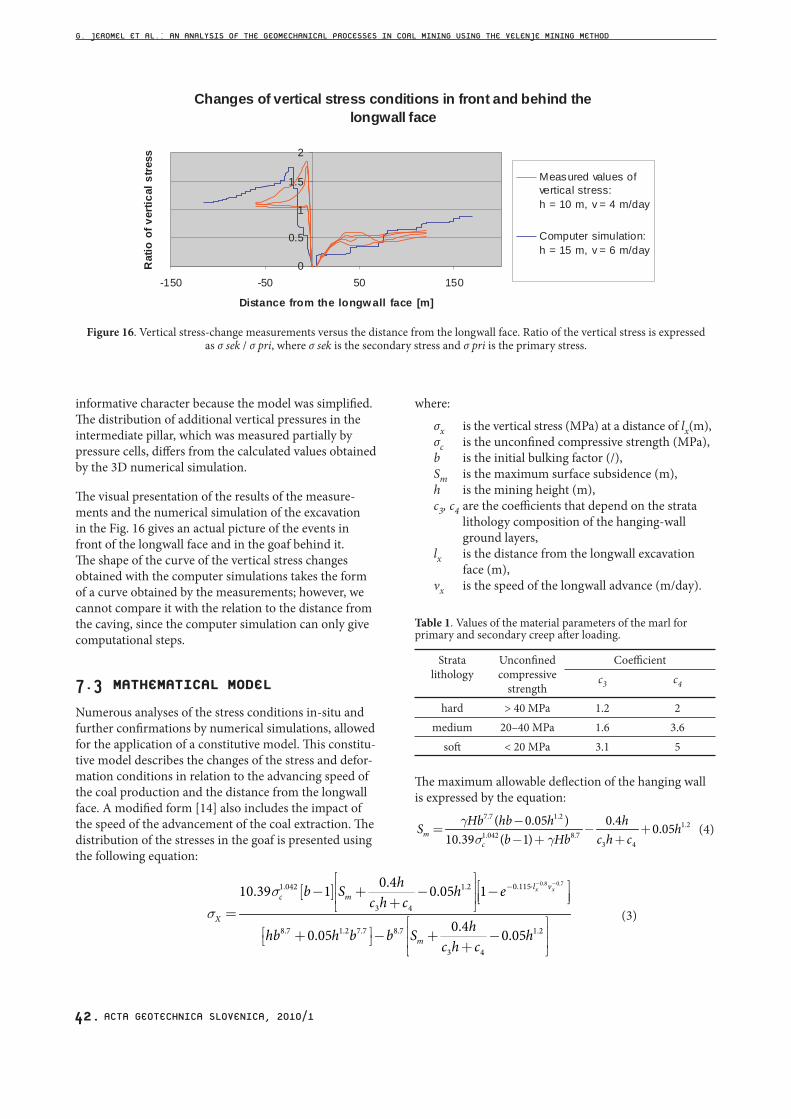
The visual presentation of the results of the measure-ments and the numerical simulation of the excavation in the Fig. 16 gives an actual picture of the events in front of the longwall face and in the goaf behind it. The shape of the curve of the vertical stress changes obtained with the computer simulations takes the form of a curve obtained by the measurements; however, we cannot compare it with the relation to the distance from the caving, since the computer simulation can only give computational steps.
7.3 MATHEMATICAL MODEL
Numerous analyses of the stress conditions in-situ and further confirmations by numerical simulations, allowed for the application of a constitutive model. This constitu-tive model describes the changes of the stress and defor-mation conditions in relation to the advancing speed of the coal production and the distance from the longwall face. A modified form [14] also includes the impact of the speed of the advancement of the coal extraction. The distribution of the stresses in the goaf is presented using the following equation:
Changes of vertical stress conditions in front and behind the
longwall face
0
0.5
1
1.5
2
-150 -50 50 150
Distance from the longw all face [m]
Rati
oo
fv
ert
ical
str
ess
Measured values of
vertical stress:
h = 10 m, v = 4 m/day
Computer simulation:
h = 15 m, v = 6 m/day
Figure 16. Vertical stress-change measurements versus the distance from the longwall face. Ratio of the vertical stress is expressedas σ sek / σ pri, where σ sek is the secondary stress and σ pri is the primary stress.
where:
σx is the vertical stress (MPa) at a distance of lx(m), σc is the unconfined compressive strength (MPa),
b is the initial bulking factor (/),Sm is the maximum surface subsidence (m),
h is the mining height (m),c3, c4 are the coefficients that depend on the strata lithology composition of the hanging-wall ground layers,lx is the distance from the longwall excavation face (m),
νx is the speed of the longwall advance (m/day).
Table 1. Values of the material parameters of the marl for primary and secondary creep after loading.
Stratalithology
Unconfined compressive
strength
Coefficientc3 c4
hard > 40 MPa 1.2 2medium 20–40 MPa 1.6 3.6
soft < 20 MPa 3.1 5
The maximum allowable deflection of the hanging wall is expressed by the equation:
7.7 1.21.2
1.042 8.73 4
( 0.05 ) 0.4 0.0510.39 ( 1)m
c
Hb hb h hS hb Hb c h c
gs g
-= - +- + +
(4)
[ ]0.8 0.70.1151.042 1.2
3 4
8.7 1.2 7.7 8.7 1.2
3 4
0.410.39 1 0.05 1
0.40.05 0.05
x xl vc m
X
m
hb S h ec h c
hhb h b b S hc h c
ss
- -- ⋅é ù é ùê ú- + - -ê úê ú ë û+ë û= é ù
ê úé ù+ - + -ë û ê ú+ë û
(3)
G. JEROMEL ET AL.: AN ANALYSIS OF THE GEOMECHANICAL PROCESSES IN CORL MINING USING THE VELENJE MINING METHOD

ACTA GEOTECHNICA SLOVENICA, 2010/1 43.
where
H is the depth of mine exploitation working (m), γ is the unit weight of the hanging-wall ground
layer (kN/m3), b is the initial bulking factor (/), σc is the unconfined compressive strength of the
ground layer (MPa), h is the mining height (m), c3, c4 are the coefficients that depend on strata
lithology in the hanging wall.
Fig. 17 shows how the vertical stresses would increase in the goaf with the distance from the observation point, using the proposed mathematical model.
The distribution of the stresses in front of the face is expressed with the following equation:
and with the equation:4 3 2
2 0.0003 0.0128 0.2101 1,2564 0.0019X x x x xs =- - - - - (6)
where σx1 is the vertical stress in front of the longwall face
at the distance x1 (MPa), σx2 is the vertical stress in front of the longwall face
at the distance x2 (MPa), h is the mining height (m), x is the distance from the longwall face (m).
Changes in the curve occur at the point where:
1 2X X xs s= 15 5
10 2.75h m x hh m x h= =-= =-
(7)
This curve shows the location of the prediction points where the ground pressure starts to increase in the surrounding areas of the longwall face. The graph in
0
0.2
0.4
0.6
0.8
1
1.2
0 100 200 300 400 500 600
Distance into the goa f [m]
Rati
oo
fv
ert
ical
str
ess
1 m / day
2 m / day
4 m / day
6 m / day
8 m / day
Measured average vertical
stress into the goaf 6m/day
sp
eed
of
fac
ead
vanc
em
ent
Figure 17. Increase of the vertical stresses in the goaf in relation to the distance from the observation point for different longwall excavation advancement rates. The ratio of the vertical stress is expressed as σ sek / σ pri, where σ sek is the secondary stress and σ pri is the primary stress.
4 31 0.0000064 0.00032X hx hxs =- - -
0.10.022 (1 0.045 )hx h h- + + (5)
0
0.5
1
1.5
2
2.5
3
-200 -100 0 100 200 300 400 500 600
Distance from the longw all face [m]
Rati
oo
fv
ert
ical
str
ess
Mathemat ical model
h = 15 m, v = 6 m/day
Mathemat ical model
h = 10 m, v = 4 m/day
Computer simulation:
h = 15 m, v = 6 m/day
Figure 18. Measurements of the changes in the vertical stresses in relation to the distance from the longwall face. The ratio of the vertical stress is expressed as σ sek / σ pri, where σ sek is the secondary stress and σ pri is the primary stress.
1 m / day
2 m / day
4 m / day
6 m / day
8 m / day
Measured average vertical
stress into the goaf 6m/day
sp
eed
of
fac
ead
vanc
em
ent
Changes of vertical stress conditions in front and behind the
longwall face
Increase of vertical stresses in the goaf
G. JEROMEL ET AL.: AN ANALYSIS OF THE GEOMECHANICAL PROCESSES IN CORL MINING USING THE VELENJE MINING METHOD

ACTA GEOTECHNICA SLOVENICA, 2010/144.
Figure 19. 3D model of the stress distribution in the surrounding areas of the longwall face based on the predictions madeby the mathematical model. The horizontal dimensions of the monitored area are expressed in [m], the vertical line
represents the ratio of the vertical stress expressed as σ sek / σ pri, where σ sek is the secondary stress and σ priis the primary stress. The length of longwall excavation face is 150 m.
G. JEROMEL ET AL.: AN ANALYSIS OF THE GEOMECHANICAL PROCESSES IN CORL MINING USING THE VELENJE MINING METHOD

ACTA GEOTECHNICA SLOVENICA, 2010/1 45.
Fig. 18 shows the comparison of the curves, i.e., the ratio between secondary and primary stresses with the distance from the longwall face.
8 CONCLUSIONS
Numerical simulations of sub-level coal mining using the finite-difference method gave the results that are compara-ble with the values obtained by the in-situ measurements during coal excavation at different locations in the Velenje Coal Mine. The data was processed and confirmed within extensive geotechnical analyses of the simulations of the Velenje mining method (VMM) in different ground-layer conditions that occur in the Velenje Coal Mine. Calcula-tions of the secondary stress–strain fields obtained by the simulation of coal mining at the upper excavation section contributed to a better understanding of complex caving processes that actually occur in the goaf.
In particular, the analyses that were carried out to compare the results of the mathematical model and the actually measured vertical stresses showed that the method of the calculation is suitable for practical appli-cations. Problems which were solved, i.e., designing the intermediate pillars and for determining the distances between mine objects in order to ensure the required stability during the lifetime of a mine, confirmed the proposed mathematical and numerical models.
With 3D numerical simulations and using a mathemati-cal model based on the analyses of the simulations using the FLAC 3D software package, we reconfirmed that sub-level mining is accompanied by large deformations in the surrounding ground layers.
A similar analysis regarding time-dependent processes during mining activities shows that it depends on the degree of compression of the goaf material’s additional stresses in the undisturbed hanging-wall ground layers and of the excavation time schedule, while considering the longwall speed advancement.
Individual excavation phases, which run in planned sequences, are also important for the assessment of comprimation effects in the goaf in real time.
In any case, modelling of the caving process by using the finite-difference method with simulations of the advancement of longwall coal mining is a suitable method for analysing intensive changes in the caved ground, which, among other things, helps with a better understanding of the caving process.
The comparison of the results of the calculations with the values obtained by in-situ measurements showed
that the used analyzing method was acceptable for solv-ing real problems in longwall coal mining.
REFERENCES
[1] BRADY B. H. G., BROWN E. T. (1985). Rock Mechanics For Underground Mining. London: George Allen & Unwin (Publishers) Ltd.. 527.
[2] CHOI D. S., McCAIN D. L. (1980). Design of long-wall systems. Littleton: Trans Soc Min Eng AIME, 268, 1761–1764.
[3] Flac 3D – Fast Lagrangian Analysis of Continua in 3 Dimensions. (2005). Version 3.0. User's Guide. Minneapolis: Itasca Consulting Group, Inc.
[4] S. Janežič in sod. (1987). Študija za reševanje problematike varnega odkopavanja in določitev kriterijev za projektiranje in odkopavanje premoga pod vodonosnimi plastmi v jamah RLV, Rudnik Lignita Velenje, Velenje.
[5] G. Jeromel. (2004). Numerična simulacija rušnih procesov pri odkopavanju premoga, Diplomsko delo, Ljubljana.
[6] King HJ, Whittaker BN. (1971). A review of current knowledge on roadway behaviour, especially the problems on which further information is required. Proceedings of the Symposium on Strata Control in Roadways. London: Inst. Min. Met.
[7] M. Lenart in sod. (1996). Velenjska odkopna metoda: rudarski projekt na Premogovniku Velenje. Project No: RP – 36/95 LM. Velenje.
[8] J. Likar in sod. (2007). Numerična tridimenzionalna raziskava rušnih procesov v različnih geološko geotehničnih in rudarsko tehničnih pogojih, Raziskovalna naloga. Velenje: Premogovnik Velenje, Ljubljana: Univerza v Ljubljani, NTF-OGR. 181.
[9] Mark C. (1990). Pillar design methods for longwall mining. BuMines IC 9247.
[10] Razprave na 6. simpozij jugoslovanskega društva za mehaniko hribin in podzemna dela. Knjiga 1: referati. Titovo Velenje. (1985).
[11] National Coal Board (NCB). (1975). Subsidence engineer’s handbook. NCB Mining Department; London.
[12] Trueman R. (1990). Finite element analysis for the establishment of stress development in a coal mine caved waste. Min Sci Technol.
[13] Wilson AH. (1981). Stress, stability in coal ribsides and pillars. Proceedings of the First Conference on Ground Control in Mining, Morgantown.
[14] Yavuz H. (2003). An estimation method for cover pressure re-establishment distance and pressure distribution in the goaf of longwall coal mines. Department of Mining Engineering, Suleyman Demirel University, Turkey.
G. JEROMEL ET AL.: AN ANALYSIS OF THE GEOMECHANICAL PROCESSES IN CORL MINING USING THE VELENJE MINING METHOD