an analysis of cause and effect relations in diagnostic relations of
TRANSCRIPT
Zeszyty Naukowe 31(103) 5
Scientific Journals Zeszyty Naukowe Maritime University of Szczecin Akademia Morska w Szczecinie
2012, 31(103) pp. 5–13 2012, 31(103) s. 5–13
An analysis of cause and effect relations in diagnostic relations of marine Diesel engine turbochargers
Andrzej Adamkiewicz
Maritime University of Szczecin, Faculty of Mechanical Engineering Diagnostics and Machine Repairs Department 70-205 Szczecin, ul. Podgórna 51/53, e-mail: [email protected]
Key words: diagnostic relations, turbocharger, maintenance, Diesel engines
Abstract The article justifies the need to analyse diagnostic relations for turbocharger operation purposes. Types of
turbochargers most frequently used in modern marine engines have been presented. Turbocharger
decomposition has been conducted on a selected example. The influence of typical inefficiencies in respect to
symptom value changes has been worked out for each heat engine and sub-system. Validation of selected
cause and effect relations has been based on operational experience in the technical scale.
Introduction
The reliability of evaluation of the technical
condition of marine engine sub-systems and the
adequacy of undertaken decisions poses a major
task in the operation process of marine main en-
gines. Regardless of the performance conditions, as
well as the moment of the engine technical condi-
tion evaluation, the reliability of the functional dia-
gnostic test, including the relations of parameter –
symptom – inefficiency, is of primary significance.
Methods applied for the purpose of diagnosing
the engines, including also the turbochargers, could
utilise the parameters of the main working medium
participating in energy conversion and the parame-
ters of the accompanying processes.
Since a turbocharger is a marine engine sub-
unit, influencing the power output, its dynamic
properties and reliable operation, for the purpose of
evaluation of the technical condition of the turbo-
charger unit operational and energy parameters,
as well as vibration signals are used as a compre-
hensive and universal set of diagnostic parameters
[1, 2, 3].
Turbocharger operation conditions, complexity
of their construction and restricted controllability
of their functional features impose the application
of turbocharger parametric identification proce-
dures [1, 4, 5]. In the majority of turbocharger
constructions a complete diagnostic survey cannot
be performed due to the limited measurement
accessibility.
In marine conditions there is no possibility to
simulate a degradation state in order to experimen-
tally identify diagnostic relations and their effect on
turbocharger functional features.
Thus, the obtained operational experience can-
not be arranged into cause and effect relations and
is not used in a systematic manner at the stage
of diagnostic concluding and decision making on
the scope of service. A limited access to manufac-
turer’s information makes operational practice de-
pendent on the authorised – ship owner’s methods
of proceeding. Therefore, the need to determine the
nature of their mutual relations arises.
The purpose of this article is to make an attempt
at recognising diagnostic relations in the evaluation
of the technical condition of a marine main engine
turbocharger using a method based on intuition
modelling techniques, verified by the machinery
personnel expert knowledge, based on the opera-
tional diagnostic experience in the technical scale.
Turbochargers of modern marine Diesel engines
Nowadays, marine Diesel engines are super-
charged by means of turbochargers. Both, the two-
Andrzej Adamkiewicz
6 Scientific Journals 31(103)
-stroke slow-speed engines, as well as the four-
-stroke, medium-and high-speed engines are manu-
factured as supercharged. Differences consist in the
manner of their charging and the mode of turbine
supply with the exhaust gas. In large, two-stroke,
slow-speed engines the applied charging system is
of the exhaust gas supply constant pressure,
whereas in the four-stroke, medium- and high-
-speed engines pulsating charging is applied. In the
constant pressure systems, the exhaust gas leaving
the engine working spaces gathers in the exhaust
gas manifold where its kinetic energy is trans-
formed into potential energy which results in stabi-
lisation of its pressure. An analysis of turbocharger
applications in marine engine charging systems
indicates the domination of marine turbocharger
models contemporarily constructed by three manu-
facturers: MAN Diesel & Turbo, ABB and Mitsu-
bishi [6, 7, 8, 9, 10, 11].
MAN Diesel & Turbo factory produces turbo-
chargers of the following types: TCR, NR, TCA
and NA differing from one another in rotor unit
constructions (with radial or axial machines) and
organisation of the inlet and outlet of the air and
exhaust gas. They have been built as machines with
the non-cooled housings, lubricated by the engine
lubrication system, with high efficiency, reliable
and durable, easy to use and operate. The materials
of the rotor unit and turbine housing are adjusted to
being supplied with the products of burning of
marine distillate, residual fuels and natural gas.
Turbochargers of the TCR type are provided with
a single-stage radial compressor and a radial turbine
supplied with exhaust gas of the permissible tem-
perature of 700°C and the compression up to 5.4
[8, 12].
Constant pressure turbochargers also include
turbochargers of the TCA type with single-stage
axial turbines supplied with exhaust gas of maxi-
mum temperature of 500°C for the two-stroke
engines and 650°C for the four-stroke engines and
permissible compression up to 5.5.
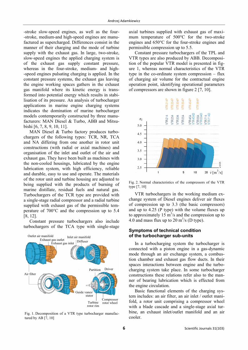
Constant pressure turbochargers of the TPL and
VTR types are also produced by ABB. Decomposi-
tion of the popular VTR model is presented in fig-
ure 1, whereas normal characteristics of the VTR
type in the co-ordinate system compression – flux
of charging air volume for the contractual engine
operation point, identifying operational parameters
of compressors are shown in figure 2 [7, 10].
Fig. 2. Normal characteristics of the compressors of the VTR
type [7, 10]
VTR turbochargers in the working medium ex-
change system of Diesel engines deliver air fluxes
of compression up to 3.3 (the basic compressors)
and up to 4.25 (P type) with the volume fluxes up
to approximately 15 m3/s and the compression up to
4.0 and mass flux up to 20 m3/s (D type).
Symptoms of technical condition of the turbocharger sub-units
In a turbocharging system the turbocharger is
connected with a piston engine in a gas-dynamic
mode through an air exchange system, a combus-
tion chamber and exhaust gas flow ducts. In their
spaces interactions between engine and the turbo-
charging system take place. In some turbocharger
constructions these relations refer also to the man-
ner of bearing lubrication which is effected from
the engine circulation.
Basic functional elements of the charging sys-
tem includes: an air filter, an air inlet / outlet mani-
fold, a rotor unit comprising a compressor wheel
with a blade cascade and a single-stage axial tur-
bine, an exhaust inlet/outlet manifold and an air
cooler.
C
]/sm[3
v
Air filter
Partition Driver
Compressor rotor wheel
Guide vanes/ stator
Turbine rotor rim
Diffuser
Inlet air manifold
Exhaust gas inlet
Outlet air manifold Exhaust gas outlet
Fig. 1. Decomposition of a VTR type turbocharger manufac-
tured by AB [7, 10]
5.0
4.5
4.0
3.5
3.0
2.5
An analysis of cause and effect relations in diagnostic relations of marine Diesel engine turbochargers
Zeszyty Naukowe 31(103) 7
Inlet air filter and manifold
Turbochargers supply marine engines with
a mixture of air, steam, precipitation droplets, sea
aerosol containing salts and biological particles, oil
and exhaust gas vapours and in port and land areas
also industrial dust. Their penetration into the tur-
bocharger and engine flow ducts significantly
affects the quality of energy conversion and causes
degradation of the technical condition of sub-units
of the engine supercharging system [2, 13]. There-
fore, ensuring the cleanliness of the air at the
engine inlet remains an important operational task.
Regardless of the construction, filters during opera-
tion display the following inefficiencies:
– increase of the flow resistance;
– loss of filtering properties;
– loss of tightness.
The increase of the flow resistance is caused by
excessive filter contamination which causes an
increase in flow resistance in the system.
Filter tightness loss may be caused by loosening
of the housing, or cover fixing bolts or due to the
cracking of any filter elements.
Loss of filtering properties of the filter is most
frequently related with the break in the filtering
system / package. This kind of damage leads to the
fast contamination of the air inlet system. During
the filtration process the filtering material con-
stantly fills with the contaminants. As filter struc-
tures get contaminated, the flow resistance and
filtering efficiency grows. Upon reaching a limiting
value of the adhesion force of the agglomerates to
the fibres, the range of filter stable operation ends.
During the filter operation, aerodynamic resistance
increases, in the effect of porosity decrease, parti-
cles are torn away from the fibres. When the filter
structure gets incorrect, contamination gets through
the filter, and then filtering efficiency drops.
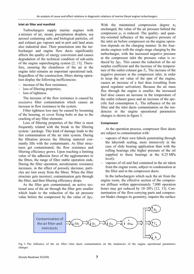
As the filter gets contaminated, an active sec-
tional area of the air through the filter gets smaller
which leads to the reduction of the air pressure
value before the compressor by the value of ΔpF.
With the maintained compression degree πS
unchanged, the value of the air pressure behind the
compressor p2 is reduced. The quality- and quan-
tity-oriented influence of the negative pressure of
the inlet air before compressor on the engine opera-
tion depends on the charging manner. In the four-
stroke engines with the single-stage charging by the
turbocharger, with the increased negative pressure
at the compressor inlet the pressure value is re-
duced by ΔpF. This causes the reduction of the air
surplus coefficient and the increase of the tempera-
ture of the outlet exhaust gas T4. The increase of the
negative pressure at the compressor inlet, in order
to keep the set value of the rpm of the engine,
causes an increase of a fuel dose (resulting from
speed regulator activation). Because the air mass
flux through the engine is smaller, the increased
fuel dose causes an increase in the temperature of
the outlet exhaust gases and an increase of the spe-
cific fuel consumption be. The influence of the air
filter and the inlet ducts contamination on the ten-
dencies in the engine operational parameters
changes is shown in figure 3.
Compressor
At the operation process, compressor flow ducts
are subject to contamination with:
– vapours of their own luboils penetrating through
the labyrinth sealing, more intensively in the
case of slide bearing application than with the
rolling bearings (the higher pressure of the oil
supplied to these bearings at the 0.25 MPa
level);
– vapours of oil and fuel contained in the air taken
from the engine room, subject to condensation at
the filter and in the compressor ducts.
In the turbochargers which suck the air from the
engine room, the effective section of the compres-
sor diffuser within approximately 7,000 operation
hours may get reduced by 10–20% [12, 13]. Con-
tamination of the flow-carrying parts and compres-
sor blades changes its geometry, impairs the surface
Fig. 3. The influence of the air filter / inlet ducts contamination on the tendencies of the engine operational parameters
changes
Andrzej Adamkiewicz
8 Scientific Journals 31(103)
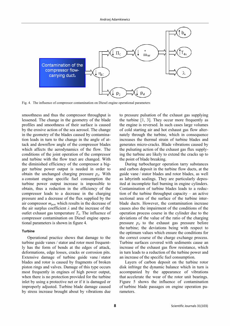
smoothness and thus the compressor throughput is
lessened. The change in the geometry of the blade
profiles and smoothness of their surface is caused
by the erosive action of the sea aerosol. The change
in the geometry of the blades caused by contamina-
tion leads in turn to the change in the angle of at-
tack and downflow angle of the compressor blades
which affects the aerodynamics of the flow. The
conditions of the joint operation of the compressor
and turbine with the flow tract are changed. With
the diminished efficiency of the compressor a big-
ger turbine power output is needed in order to
obtain the unchanged charging pressure pd. With
a constant engine specific fuel consumption the
turbine power output increase is impossible to
obtain, thus a reduction in the efficiency of the
compressor leads to a decrease in the charging
pressure and a decrease of the flux supplied by the
air compressor mpow which results in the decrease of
the air surplus coefficient λ and the increase of the
outlet exhaust gas temperature T4. The influence of
compressor contamination on Diesel engine opera-
tional parameters is shown in figure 4.
Turbine
Operational practice shows that damage to the
turbine guide vanes / stator and rotor most frequent-
ly has the form of bends at the edges of attack,
deformations, edge losses, cracks or corrosion pits.
Extensive damage of turbine guide vane / stator
blades and rotor is caused by fragments of broken
piston rings and valves. Damage of this type occurs
most frequently in engines of high power output,
when there is no protection provided for the turbine
inlet by using a protective net or if it is damaged or
improperly adjusted. Turbine blade damage caused
by stress increase brought about by vibrations due
to pressure pulsation of the exhaust gas supplying
the turbine [1, 3]. They occur more frequently as
the engine is reversed. In such cases large volumes
of cold starting air and hot exhaust gas flow alter-
nately through the turbine, which in consequence
increases the thermal strain of turbine blades and
generates micro-cracks. Blade vibrations caused by
the pulsating action of the exhaust gas flux supply-
ing the turbine are likely to extend the cracks up to
the point of blade breaking.
During turbocharger operation tarry substances
and carbon deposit in the turbine flow ducts, at the
guide vane / stator blades and rotor blades, as well
as labyrinth sealings. They are particularly depos-
ited at incomplete fuel burning in engine cylinders.
Contamination of turbine blades leads to a reduc-
tion of the turbine throughput capacity – an active
sectional area of the surface of the turbine inter-
blade ducts. However, the contamination increase
causes also the impairment of the conditions of the
operation process course in the cylinder due to the
deviations of the value of the ratio of the charging
pressure pd to the exhaust gas pressure before
the turbine; the deviations being with respect to
the optimum values which ensure the conditions for
the correct course of the charge exchange process.
Turbine surfaces covered with sediments cause an
increase of the exhaust gas flow resistance, which
in turn leads to a reduction of the turbine power and
an increase of the specific fuel consumption.
Layers of carbon deposit on the turbine rotor
disk infringe the dynamic balance which in turn is
accompanied by the appearance of vibrations
that accelerate the wear of the rotor unit bearings.
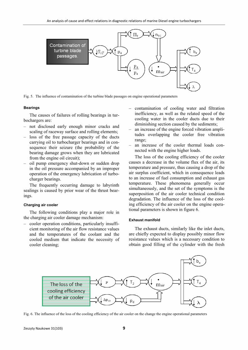
Figure 5 shows the influence of contamination
of turbine blade passages on engine operation pa-
rameters.
Fig. 4. The influence of compressor contamination on Diesel engine operational parameters
An analysis of cause and effect relations in diagnostic relations of marine Diesel engine turbochargers
Zeszyty Naukowe 31(103) 9
Bearings
The causes of failures of rolling bearings in tur-
bochargers are:
– not disclosed early enough minor cracks and
scaling of raceway surface and rolling elements;
– loss of the free passage capacity of the ducts
carrying oil to turbocharger bearings and in con-
sequence their seizure (the probability of the
bearing damage grows when they are lubricated
from the engine oil circuit);
– oil pump emergency shut-down or sudden drop
in the oil pressure accompanied by an improper
operation of the emergency lubrication of turbo-
charger bearings.
The frequently occurring damage to labyrinth
sealings is caused by prior wear of the thrust bear-
ings.
Charging air cooler
The following conditions play a major role in
the charging air cooler damage mechanism:
– cooler operation conditions, particularly insuffi-
cient monitoring of the air flow resistance values
and the temperatures of the coolant and the
cooled medium that indicate the necessity of
cooler cleaning;
– contamination of cooling water and filtration
inefficiency, as well as the related speed of the
cooling water in the cooler ducts due to their
diminishing section caused by the sediments;
– an increase of the engine forced vibration ampli-
tudes overlapping the cooler free vibration
range;
– an increase of the cooler thermal loads con-
nected with the engine higher loads.
The loss of the cooling efficiency of the cooler
causes a decrease in the volume flux of the air, its
temperature and pressure, thus causing a drop of the
air surplus coefficient, which in consequence leads
to an increase of fuel consumption and exhaust gas
temperature. These phenomena generally occur
simultaneously, and the set of the symptoms is the
superposition of the air cooler technical condition
degradation. The influence of the loss of the cool-
ing efficiency of the air cooler on the engine opera-
tional parameters is shown in figure 6.
Exhaust manifold
The exhaust ducts, similarly like the inlet ducts,
are chiefly expected to display possibly minor flow
resistance values which is a necessary condition to
obtain good filling of the cylinder with the fresh
Fig. 5. The influence of contamination of the turbine blade passages on engine operational parameters
Fig. 6. The influence of the loss of the cooling efficiency of the air cooler on the change the engine operational parameters
Andrzej Adamkiewicz
10 Scientific Journals 31(103)
charge and a complete removal of the exhaust gas
from them.
Basic inefficiencies of the exhaust ducts com-
prise their contamination caused by tarry sub-
stances depositing there, which is the result of the
incomplete fuel burning in the engine cylinders.
Excessive contamination of the exhaust ducts
brings about pressure increase of exhaust gas be-
hind the turbine p4. As a result, the gas expansion
degree in turbine πT is decreased, the turbocharger
power output and rotor rpm are diminished.
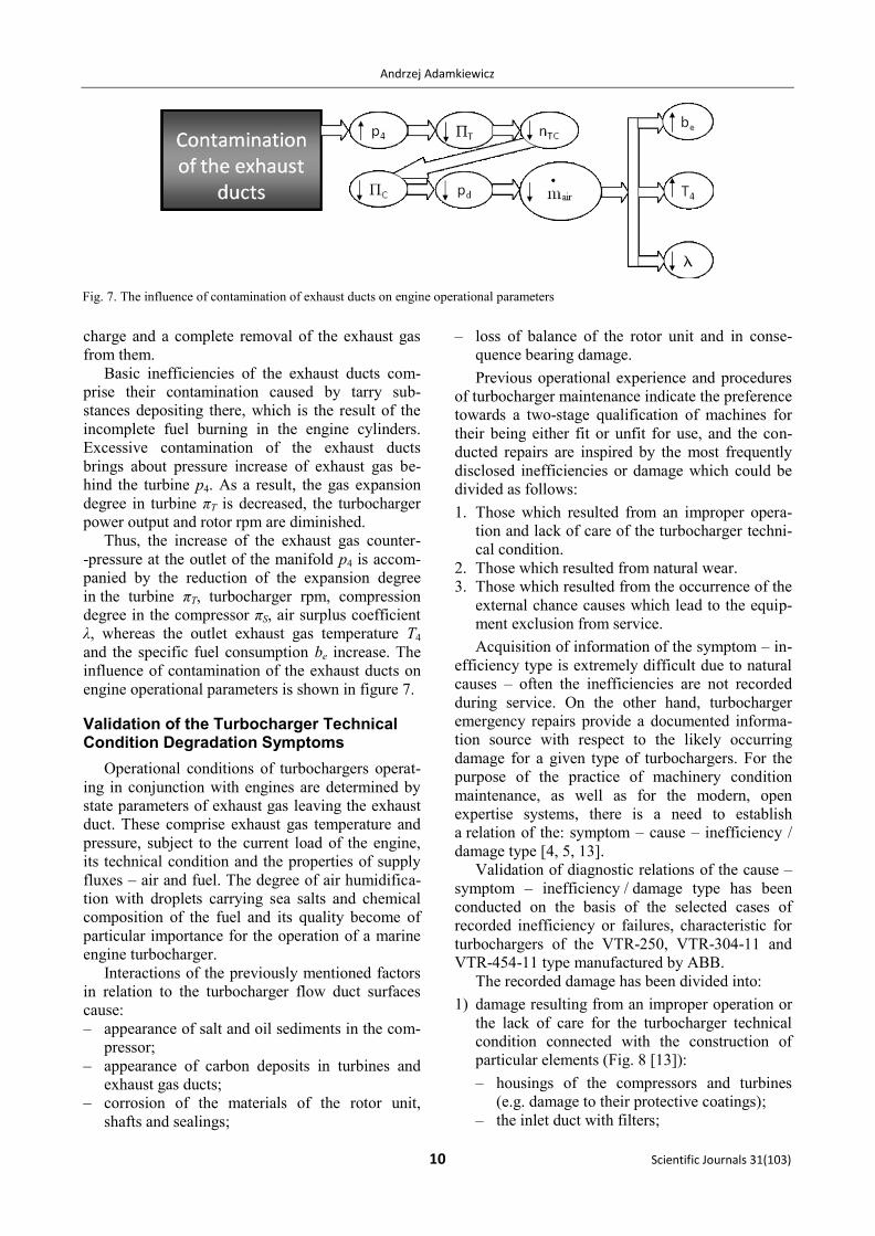
Thus, the increase of the exhaust gas counter-
-pressure at the outlet of the manifold p4 is accom-
panied by the reduction of the expansion degree
in the turbine πT, turbocharger rpm, compression
degree in the compressor πS, air surplus coefficient
λ, whereas the outlet exhaust gas temperature T4
and the specific fuel consumption be increase. The
influence of contamination of the exhaust ducts on
engine operational parameters is shown in figure 7.
Validation of the Turbocharger Technical Condition Degradation Symptoms
Operational conditions of turbochargers operat-
ing in conjunction with engines are determined by
state parameters of exhaust gas leaving the exhaust
duct. These comprise exhaust gas temperature and
pressure, subject to the current load of the engine,
its technical condition and the properties of supply
fluxes – air and fuel. The degree of air humidifica-
tion with droplets carrying sea salts and chemical
composition of the fuel and its quality become of
particular importance for the operation of a marine
engine turbocharger.
Interactions of the previously mentioned factors
in relation to the turbocharger flow duct surfaces
cause:
– appearance of salt and oil sediments in the com-
pressor;
– appearance of carbon deposits in turbines and
exhaust gas ducts;
– corrosion of the materials of the rotor unit,
shafts and sealings;
– loss of balance of the rotor unit and in conse-
quence bearing damage.
Previous operational experience and procedures
of turbocharger maintenance indicate the preference
towards a two-stage qualification of machines for
their being either fit or unfit for use, and the con-
ducted repairs are inspired by the most frequently
disclosed inefficiencies or damage which could be
divided as follows:
1. Those which resulted from an improper opera-
tion and lack of care of the turbocharger techni-
cal condition.
2. Those which resulted from natural wear.
3. Those which resulted from the occurrence of the
external chance causes which lead to the equip-
ment exclusion from service.
Acquisition of information of the symptom – in-
efficiency type is extremely difficult due to natural
causes – often the inefficiencies are not recorded
during service. On the other hand, turbocharger
emergency repairs provide a documented informa-
tion source with respect to the likely occurring
damage for a given type of turbochargers. For the
purpose of the practice of machinery condition
maintenance, as well as for the modern, open
expertise systems, there is a need to establish
a relation of the: symptom – cause – inefficiency /
damage type [4, 5, 13].
Validation of diagnostic relations of the cause –
symptom – inefficiency / damage type has been
conducted on the basis of the selected cases of
recorded inefficiency or failures, characteristic for
turbochargers of the VTR-250, VTR-304-11 and
VTR-454-11 type manufactured by ABB.
The recorded damage has been divided into:
1) damage resulting from an improper operation or
the lack of care for the turbocharger technical
condition connected with the construction of
particular elements (Fig. 8 [13]):
– housings of the compressors and turbines
(e.g. damage to their protective coatings);
– the inlet duct with filters;
Fig. 7. The influence of contamination of exhaust ducts on engine operational parameters
An analysis of cause and effect relations in diagnostic relations of marine Diesel engine turbochargers
Zeszyty Naukowe 31(103) 11
a) b)
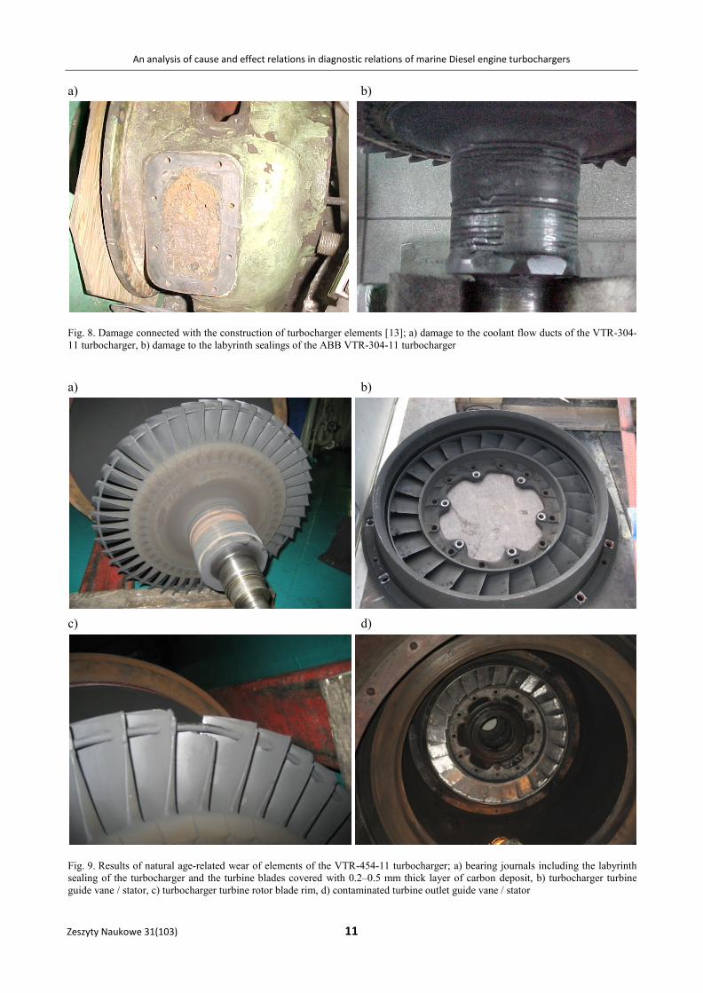
Fig. 8. Damage connected with the construction of turbocharger elements [13]; a) damage to the coolant flow ducts of the VTR-304-
11 turbocharger, b) damage to the labyrinth sealings of the ABB VTR-304-11 turbocharger
a) b)
c) d)
Fig. 9. Results of natural age-related wear of elements of the VTR-454-11 turbocharger; a) bearing journals including the labyrinth
sealing of the turbocharger and the turbine blades covered with 0.2–0.5 mm thick layer of carbon deposit, b) turbocharger turbine
guide vane / stator, c) turbocharger turbine rotor blade rim, d) contaminated turbine outlet guide vane / stator
Andrzej Adamkiewicz
12 Scientific Journals 31(103)
– the own oil system or the engine oil installa-
tion of.
2) Damage resulting from the natural ageing / wear
processes, related to the turbocharger active
service time (Fig. 9).
3) Damage resulting from external chance causes
(Figs 10 and 11).
These can be regarded as the random events,
related to faulty functioning of an antropo-
technical couple: human – engine (a nut left
in the turbine, not renewed oil). The most fre-
quently encountered damage of this type results
from non-compliance with the assembly tech-
nology, e.g.: positioning of bearings incom-
patible with manufacturer’s recommendations,
application of the substitute sealings etc.
Conclusions
Relations between operational parameters of
a turbocharging system and an engine, presented
graphically in the figures 3–7, generally point to
three values that inform about an impaired technical
condition of the object: the increase of the specific
fuel consumption be, the exhaust gas temperature T4
and the decreasing air surplus coefficient value λ.
The knowledge of the symptoms regarding individ-
ual sub- units or elements is required in order to
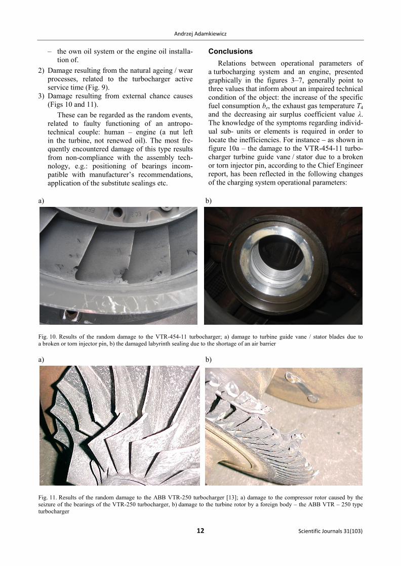
locate the inefficiencies. For instance – as shown in
figure 10a – the damage to the VTR-454-11 turbo-
charger turbine guide vane / stator due to a broken
or torn injector pin, according to the Chief Engineer
report, has been reflected in the following changes
of the charging system operational parameters:
a) b)
Fig. 10. Results of the random damage to the VTR-454-11 turbocharger; a) damage to turbine guide vane / stator blades due to
a broken or torn injector pin, b) the damaged labyrinth sealing due to the shortage of an air barrier
a) b)
Fig. 11. Results of the random damage to the ABB VTR-250 turbocharger [13]; a) damage to the compressor rotor caused by the
seizure of the bearings of the VTR-250 turbocharger, b) damage to the turbine rotor by a foreign body – the ABB VTR – 250 type
turbocharger
An analysis of cause and effect relations in diagnostic relations of marine Diesel engine turbochargers
Zeszyty Naukowe 31(103) 13
– excessive temperature of the exhaust gas from
the cylinders and before the turbocharger T4;
– lowered charging air pressure pd;
– lowered rpm of the n turbocharger rotor unit.
As turbine ducts had been washed, the described
symptoms became more profound which was re-
flected by the change of the value of the operational
parameters / symptoms in accordance with the
tendencies shown in figure 5, and confirmed by
operational measurements.
Any attempt to determine the technical condi-
tion of a turbocharger and the location of the opera-
tional fault, with a view to the compact nature of its
construction, and its functional and critical features,
is associated with putting the engine out of service
with all the technical and economic consequences.
While striving to eliminate this negative situation in
the operation, one is forced to search for methods to
conduct a reliable diagnostic test during the service,
without disconnecting the turbocharger from the
engine. Validation of the cause and effect relations
in the diagnostic relations, acquired on the example
of the VTR-454-11 turbocharger, justifies the need
for establishing a diagnostic test based on previ-
ously studied relations.
References
1. ADAMKIEWICZ A., MICHALEC G.: General Diagnostic
Model of a Marine Diesel Engine. Turbocharger, Marine
Technology Transaction, Vol. 11, 2000, 25–40.
2. ADAMKIEWICZ A.; MICHALEC G.: Ocena stanu dynamiczne-
go turbodoładowarki okrętowego silnika spalinowego.
Problemy Eksploatacji, Zeszyty Naukowe Instytutu Tech-
nologii Eksploatacji, Nr 2/99, Radom 1999.
3. MICHALEC G., POLANOWSKI S., ŁUTOWICZ M.: Turbodoła-
dowarka silnika okrętowego jako obiekt diagnostyki. Mate-
riały Konferencji DIAGNOSTYKA’99 – ATR Bydgoszcz
– Borówno, czerwiec 1999.
4. ADAMKIEWICZ A.: MICHALEC G.: Identyfikacja relacji dia-
gnostycznych w turbodoładowarce okrętowego silnika spa-
linowego. Materiały konferencji DIAGNOSTYKA’99,
ATR Bydgoszcz – Borówno, czerwiec 1999, t. I, 7–18.
5. MICHALEC G., ADAMKIEWICZ A., WITKOWSKI K.: Model
Diagnostic Relations in a Marine Diesel Turbocharger Sys-
tem. II Internationally Technical Conference Explo-Diesel
& Gas Turbine’01, Gdańsk – Międzyzdroje – Kopenhaga,
April 23–27, 2001.
6. ABB Turbochargers TPL – B, ABB 2006.
7. ABB Turbocharging VTR, ABB 2009.
8. Exhaust Gas Turbochargers. Programme 2011. MAN Die-
sel & Turbo.
9. TurboNews TCS-PTG. 2007. MAN Diesel & Turbo.
10. www.abb.com/product
11. www.mhi.co.jp
12. The New Generation of MAN B&W Turbochargers, MAN
B & W Diesel AG. Germany md 019705.
13. ADAMKIEWICZ A., MICHALEC G.: Problematyka eklsploata-
cji turbosprężarek okrętowych tłokowych silników spali-
nowych. Budownictwo Okrętowe i Gospodarka Morska,
Nr 4 (501), Gdańsk, kwiecień 2001, 23–25.
Other
14. GIRTLER J.: Diagnostyka jako warunek sterowania eksplo-
atacją okrętowych silników spalinowych. Studia Nr 28.
WSM, Szczecin 1997.
The study financed from the means for the edu-
cation within 2009–2012 as own research project
No. NN 509404536