an aerodynamic analysis of a spinning missile with ... generic spinning missile with dithering...
TRANSCRIPT

American Institute of Aeronautics and Astronautics
1
AbstractA genericspinningmissilewith ditheringcanardsis
usedto demonstrate the utility of an oversetstructuredgrid approach for simulating the aerodynamics ofrolling airframemissilesystems.Theapproach is usedto generate a modestaerodynamic databasefor thegeneric missile. The database is populated withsolutionsto theEulerandNavier-Stokesequations.It isused to evaluate grid resolution requirements foraccurate predictionof instantaneousmissileloadsandtherelativeaerodynamicsignificanceof angle-of-attack,canard pitching sequence, viscouseffects,and roll-rateeffects. A novel analytical method for inter- andextrapolation of database results is also given.
1. INTRODUCTION
Simulationof theaerodynamicsof rolling airframemissilesystemsposesignificantchallengesfor any com-putationalapproach. Applicationsof practical interestare characterizedby complex vortical flow and shockstructures. In addition, the geometryof thesemissilesystemscanbevery complex, involving relative motionbetweenmissilebody andcontrol surfaces. The flowsarealsoinherentlyunsteady. Theaim of this paperis todemonstratethe utility of Chimera1 oversetstructuredgrid domain decompositionmethodsin the efficientgenerationof high fidelity aerodynamicsimulationsforthis class of problems.
A generic rolling airframe missile is defined inorder to demonstratethe advantagesand limitations ofanoversetgrid approach.Thepaperprovidesa techni-cal descriptionof the genericmissile and the specificcomputationalmethodshere employed, and completediscussionsof the caseconditionsand correspondingsimulation results. The set of simulationsconsideredare designedto demonstratethe level of resolutionrequiredfor accuratepredictionof surfaceloadsandtodeterminethe relative aerodynamicsignificanceof vis-
cousandmissileroll-rateeffects. Theaerodynamicper-formanceof themissileasa functionof angle-of-attackand canardpitching sequenceis also considered. Anovel analytical method for describing these perfor-mance characteristicsis given. A brief summary,acknowledgements,and list of referencesare providedat the end of the paper.
2. ROLLING AIRFRAME CONFIGURATION
The genericrolling airframe missile employed inthepresentwork is referredto asFM-3. TheFM-3 mis-silehasahemisphericalnose,cylindrical body, four fins,andtwo canards.Detailsof thegeometriccomplexity ofthe missile are illustrated in Figure 1.
c)
a)
Figure 1. FM-3 missile geometry. a) Top view ofentire missile. b) Fins. c) Close-up of canard.
groove
cut-out
b)
shaft
An Aerodynamic Analysis of a Spinning Missile with Dithering Canards
Tor A. Nygaard* and Robert L. Meakin†
Army/NASA Rotorcraft DivisionNASA Ames Research CenterMoffett Field, CA 94035-1000
* Research Scientist, ELORET Corp., Member AIAA† Senior Research Scientist, U.S. Army AFDD (AMCOM), Senior Member AIAA
This material is declared a work of the U.S. Government and isnot subject to copyright protection in the United States.
https://ntrs.nasa.gov/search.jsp?R=20030071145 2018-05-23T09:00:10+00:00Z

American Institute of Aeronautics and Astronautics
2
0 30 60 90 120 150 180 210 240 270 300 330 360−2
−1.5
−1
−0.5
0
0.5
1
1.5
2
Roll Angle [Degrees]
Con
trol
Sig
nals
and
Nor
mal
ized
Pitc
h [−
]
Canard Pitching Algorithm
CommandDitherCommand+DitherCanard Pitch
Thefins aredesignedto inducemissilespin,whiledirectionalcontrol is actuatedvia canarddithering. Asthe missile spins,the canardpitch position follows anactuatorsignal with constantpitch rate. The actuatorsignalflip-flops between+/- 1 accordingto the sign ofthe sum of two sine-waves called the commandanddither signals. The amplitudeof the commandsignalrelative to thedithersignalis calledthecommandlevel,andreflectsthestrengthof theattemptedmaneuver. Thecommandsignal is modulatedwith the roll-rate. Thedithersignalis modulatedwith a dither frequency. Fig-ure 2 shows the canardpitching algorithm for a com-mandlevel of 100%for thespecifiedroll-rateandditherfrequency.
3. COMPUTATIONAL METHODS
3.1 Discretization Method
The “near-body” and“off-body” domainpartition-ing methoddescribedin References2 and3 is usedhereasthebasisof discretizationof theFM-3 missile. In theapproach,the near-body portion of a domainis definedto includethesurfacegeometryof all bodiesbeingcon-sideredandthe volumeof spaceextendinga shortdis-
tance away from the respective surfaces. Theconstructionof near-bodygridsandassociatedintergridconnectivity is a classicalChimera-styledecompositionof the near-body domain. It is assumedthat near-bodygrids provide grid point distributionsof sufficient den-sity to accuratelyresolve the flow physics of interest(i.e., boundary-layers,vortices,etc.) without the needfor refinement.This is a reasonableconstraintsincenear-bodygridsareonly requiredto extenda shortdis-tanceaway from bodysurfaces. Figure3 illustratesthesurfacedecompositionof the FM-3 missile and showsselectedsurfacesfrom the resultingnear-body surfaceand volume grids.
The off-body portion of the domain is definedtoencompassthe near-body domainandextendout to thefar-field boundariesof the problem. The off-bodydomain is filled with overlapping uniform Cartesiangrids of variablelevels of refinement,asshown in Fig-ure4 for theFM-3 missile. Theoff-bodygrid resolutionamplificationfactorbetweensuccessive levelsis 2. Thenear-bodyoff-bodypartitioningapproachfacilitatesgridadaptationin responseto proximity of bodycomponentsand/orto estimatesof solutionerrorwithin thetopologi-cally simple off-body grid system.
Figure 2. Canard pitching algorithm for roll-rate of 8.75 Hz, dither frequency of 35 Hz, and 100% command level.

American Institute of Aeronautics and Astronautics
3
3.2 Solution Method
The setof FM-3 missilesimulationspresentedinthis paperrepresenta wide varietyof conditionsandareproductsof theOVERFLOW-D3,5 code. OVERFLOW-D is basedon version1.6auof the well known NASAOVERFLOW6 code, but has been significantlyenhancedto accommodatemoving body applications.The OVERFLOW-D enhancementsrepresentin-coresubroutineactuatedoperationsand include the follow-ing capabilities.
i. On-the-flygenerationof off-bodygrid systems.ii. MPI6 enabled scalable parallel computing.iii. Automatic load balancing.iv. Aerodynamic force and moment computations.v. General 6-degrees-of-freedom model.vi. Rigid-body relative motion betweenan arbi-
trary number of bodies.vii. Domain connectivity.viii. Solution error estimation.ix. Grid adaptationin responseto body motion
and/or estimates of solution error.
Themajorityof theFM-3 simulationspresentedinthis paperinvolve relative motionbetweengrid compo-nents. The entire missile spins relative to the inertialoff-body grid systemand the canardsdither relative tothe missilebody. The pseudo-codebelow outlinesthegeneralprocedureusedin OVERFLOW-D to carry outsuch simulations. Of course,the flow equationsaresolved at every time-stepduring a simulation. In casesthatinvolve relative motionbetweenconfigurationcom-ponents,body dynamicsand domain connectivity are
Figure 3. FM-3 surfacegeometrydecompositionandnear-body grids. a) Surfacedecompositionof missilebody. b) Decomposition of canard surfaces andselectedsurfacesfrom correspondinggrids. c) Decom-positionof fin surfacesandselectedsurfacesfrom cor-responding grids.
Note: Surfacegeometrydecompositionandnear-body grid genera-tion accomplished using OVERGRID utility from CGT4.
a)
b)
c)
Figure 4. FM-3 near-body and off-body partitioningand selected surfaces.
Level-1
Level-2
Level-3
near-body gridcomponents

American Institute of Aeronautics and Astronautics
4
alsoaddressedat eachtime-step.In thecaseof theFM-3 missile, body dynamicssimply meansthe computa-tion of aerodynamicloadsandmoving themissilecom-ponentsaccordingto a control-law. Specifically, therotationalorientationof the missile is positionedas afunction of time and the roll-rate. The positionof thecanardsrelative to themissilebodyis determinedby thecanard dither algorithm (illustrated in Figure 2).
Sincethe missile movementis continuous,therelative positionof many grid componentschangeeverytime-step. In order for solution information to be cor-rectly exchangedbetweengrids during the simulation,the domainconnectivity solutionmustalsobe continu-ously updated. This is accomplishedautomaticallybyOVERFLOW-D.
The OVERFLOW-D processingrate for staticgeometryviscousflow applicationsis about15µsecpergrid-pointpertime-step(300MHzprocessor).For mov-ing-body problems, the processingrate is somewhatproblemdependent,but generallyfalls in theboundsof15 to 18 µsecpergrid-pointpertime-step.For theFM-3 spinningmissilecasesconsideredhere,thenumberis16.5µsecpergrid-pointpertime-step.OVERFLOW-Daccommodatesproblem sizesof more than 2 milliongrid-pointsper1 gigabyteof memory. Maximumparal-lel efficiency (percentagein high 90’s) is realizedwhenthe fewestnumberof processorsthat canaccommodatea given problemin corememoryareselected.OVER-FLOW-D can efficiently (i.e., over 70%) make useoflarger numbersof processorsfor a fixed problemsize
when eachprocessorassumesthe load of at least250thousandpoints. Load balancingis an automaticfunc-tion of OVERFLOW-D.
As indicated in the pseudo-codeabove, OVER-FLOW-D accommodatessolution adaptationbasedonthe position of near-body grid componentsand/or inresponseto estimatesof solution error. The off-bodygrid managementschemeallocateslevel-1 (finest)reso-lution grids to accommodatesignificantmotionof bodycomponentsor flow featuresbeforethenext adaptcycle.Accordingly, adapt cycles are only required periodi-cally; every 25 to 50 time-stepsin a typical unsteadysimulation.
In theFM-3 missilecasesconsideredhere,all flowfeaturesthat arelikely to have any significantaffect onthesurfaceforcesandmomentsareconfinedto thevol-ume of spacewithin a missile diameterof the bodyitself. Theseinclude canardvortices,boundarylayer,and key portions of the shock systems. Accordingly,OVERFLOW-D input is usedto allocatelevel-1 resolu-tion capacityto a distanceof 1.5 diametersfrom themissile surface, rather than enable adaptation inresponseto solutionerror. A slight savingsin computa-tional overhead is thereby gained for the present cases.
4. SIMULATION RESULTS
A setof FM-3 missilesimulationsis carriedout todemonstratethelevel of resolutionrequiredfor accuratepredictionof surfaceforcesandmomentsandto deter-mine the relative aerodynamicsignificanceof viscouseffects,missile roll-rates(Ωr), canardcommandlevels(c), andfree-streamangles-of-attack(α). A total of 31FM-3 simulationsform the basisof the material pre-sentedin this paperconcerningtheseissues.Theflightconditionsfor the casesare indicatedin Table 1. Theparametersvariedto obtainthecompletesimulationsetare free-streamangle-of-attack,canardpitch commandlevel, andmissileroll-rate. Theothersimulationparam-etersindicatedin the tableareheld fixed andarecom-mon to all cases considered.
Pseudo-Code. Solution procedure (with adaptiverefinementcapability)for unsteadyproblemsthat mayinvolve relative motion between component parts.
For N time-steps
Solve flow equations
- Body dynamics- Domain connectivity
For Moving Body Problems
- Error estimation- Off-body re-partitioning- Solution transfer- Domain connectivity
Adaptive Refinement
do every step
do every mth step
Table 1. Simulation Parameters
M∞ Mach number
Re Reynolds number
1.6
50 106×
Roll-rate
Angle-of-attack
Command levelΩr
αc 0%, 100%, 200%
0 Hz, 8.75 Hz
0o, 2o, 3o, 4o, 8o, 12o, 15oΩd Dither-frequency 35 Hz

American Institute of Aeronautics and Astronautics
5
The generalcharacteristicsof the FM-3 flow fieldare illustratedin Figure 5. Vorticesare shedfrom theinboard and outboardtips of the canardand convectdown the lengthof the missile interactingwith the vis-cousboundarylayer. Away from the influenceof theboundary layer, the outboard canard vortices twistapproximately8o around the spinning missile in onebody-lengthof travel. As canbeseenin thefigure,dis-ruptions to the boundarylayer by the inboard canardvorticesaredraggedthroughnearly45o of roll over thesameinterval. Theshockstructureis indicatedin Figure5b. Theboundarylayergrowth on theuppersurfaceofthemissileis alsovisible in thefigure. A positiveangle-of-attackandvortex/boundarylayerinteractioncombineto exaggeratethe boundarylayer thicknessdown thestream-wise axis of the missile.
4.1 Resolution Requirements
A grid refinementstudy is usedto determinethelevel of spatialresolutionneededto accuratelypredictthe integratedFM-3 surfaceloads. The significanceofgrid resolutionis evaluatedhereby comparingviscoussolutionsfor thespinningmissilecasedefinedin Table1with the variableparametersc, α, andΩr fixed at 0%,
3o, and 8.75 Hz, respectively. A very high resolutiongrid is usedto definethebaselinesolution. Mediumandcoarsesolutionsareobtainedon grids derived from thebaselinegrid with successively lower levels of spatialresolution. The qualitative effect of coarseningon thesurfacegeometryis shown in Figure 6. A very highfidelity temporal resolution(viz., 12,000time-stepspermissile revolution) is uniformly employed in all of theviscous simulations.
Thebaselinegrid for this case(finestresolution)iscomprisedof 41 million grid points and is referredtohereafterastheV1 (i.e.,“Viscous-1”)grid. Isolatedsur-facesfrom the V1 grid are shown in Figures3 and 4.Theflow characteristicsillustratedin Figure5 arefromasimulationusingtheV1 grid. All grid lengthsreferredto in the following discussionare normalizedby themissile body length. Viscous spacingnormal to thebodysurfacesis in theV1 grid. This corre-spondsto ay+ of 1 for aReynoldsnumberof 10million.This spacingis maintaineduniformly acrossthe first 6cells in the viscousdirectionandthenexpandedwith ageometricstretchingratioof 1.2to adistanceof approx-imately0.015. Themaximumspacingusedin thenear-body grids is approximatelyequal to the level-1 off-body grid spacingwhich is 0.0013,or approximately0.1% of the body length.
Figure 5. Aerodynamicsof theFM-3 spinningmissilewith ditheringcanards.a) Vortex structure. b) Shockstructure.Ωr = 8.75 Hz,c = 0%,α = 3o.
Outboard canardvortexInboard canard
vortex
Vortex/Boundary layerinteraction
a)
b)
Figure 6. Fine, medium,and coarsegrid representa-tions of FM-3 canards and fins.
V1 (fine)
V2 (medium)
V3 (coarse)
2.5 106–×

American Institute of Aeronautics and Astronautics
6
The V1 grid is the basisof the medium(V2) andcoarse(V3) grids. TheV2 grid is obtainedby deletingapproximatelyevery otherpoint from theV1 grid in allthreespatialdimensionsand resultsin a grid with justover 8 million points. Similarly, theV3 grid is obtainedfrom theV2 grid by deletingapproximatelyevery otherpoint from the V2 grid in all threespatialdimensionsandresultsin agrid with justover2 million points. Theforegoing is true subject to the following qualifications.
i. Somesurfacegrids requireredistribution and/or additionof grid-pointsto preservegeometricfeaturessuchassharpcornersthroughthe twosubsequent eliminations of every other point.
ii. Smoothingis appliedto geometricfeaturesthatare not adequatelyresolved by the coarsergrids. For theV2 grid, smoothingis appliedtothecanardcut-outandthemissilegroove. Forthe V3 grid, the canard cut-out, the canardshaftandthemissilegroove areremovedcom-pletely.
iii. The grid spacingin the surfacenormal direc-tion for theV2 grid correspondsapproximatelyto every otherpoint for the V1 grid, doublingthe initial spacing from the wall.
iv. The grid spacingin the surfacenormal direc-tion for the V3 grid startsat the surfacewiththe V2 spacingdoubled.The stretchingratiothereafteris approximatelythe sameas in theV2 grid.
Considernow thecomputedloadhistoriesobtainedfrom simulationsusingtheV1, V2, andV3 grids. Fig-ure7 shows thecomputednormalforce(Cz) historyforthe three different resolution capacities. The canardpitch anglehistory is also indicated. The V1 and V2results are in good agreement,except at maximumcanarddeflection. At high canardlift, the strongvorti-cesshedfrom thecanardsmodify thepressuredistribu-tion on the fuselageand the tail fins. Still, the roll-averagednormalforcesfrom V1 andV2 shown in Table2 differ by lessthan0.3%,indicatingneargrid conver-gencefor this quantity. The V3 result differs signifi-cantly from V1 and V2.
Thedatarepresentedin Figures8 and9 observe thesameform asthatusedin Figure7. However, Figures8and9 displaysideforce(Cy) andaxial force(Cx) histo-ries, respectively. The side forces exhibit the sameeffect as for the normal forces at maximum canarddeflection.The roll-averagedside-forcesare close tozero,with a differencebetweenV1 andV2 of lessthan0.02%of thenormalforce, indicatinggrid convergencefor this quantityalso. In contrast,the axial forces(see
Figure9), indicateasystematicshift higherfor finer res-olution. The differencebetweenV1 and V2 axialforcesis approximatelythe sameasbetweenthe corre-spondingV2 andV3 results. Clearly, grid convergenceis not apparent in the computed axial force data.
Figures10 and11 breakdown theaxial forcesintopressureandviscouscomponents.TheV2 andV3 solu-tions are almost identical for the pressurecomponent;and V1 hasa systematicshift to a higher value. Thecontribution to this shift comesmainly from theaft partof themissile. This region of theflow hascomplicatedinteractionsbetweenthe expansionwaves around theboat-tail,shocksaroundthe tail fins, andthe boundarylayer. TheV1 andV2 viscouscomponentsto theaxialforcediffer by approximately2%of thetotalaxial force,slightly lessthanthedifferencebetweentheV2 andV3results. The total roll-averagedaxial forcesareshownin Table2. Themediumandcoarsesolutionaxial forcesare 4% and 8% lower than for the correspondingfinesolution. The reasongrid convergencein axial force isnot demonstrablevia the currentsetof solutionsis notclear. It maybethatwhile theV1 grid hassufficient res-olution in the boundarylayer, the V2 and V3 viscousspacing(doubleandquadruplethat of V1) is not suffi-cient.
Figure12 shows thepitchingmoment(Cmy) aboutthecenterof gravity for theV1, V2, andV3 simulations.Themissilecenterof gravity is locatedapproximatelyatthe missilemidpoint. As is the casefor normal force,the differencesin pitching momentarelargestat maxi-mum canarddeflection. Still, the overall agreementisvery good. ThedifferencebetweentheV1 andV2 roll-averagedpitchingmomentsareapproximately1%of themaximum pitching momentduring a revolution. Theroll-averagedpitching momentsare shown in Table 2.The percentageof maximumpitching momentis usedhereas a measureof grid convergencesince the roll-averaged moments are all nearly zero.
Figure13 shows the yawing moment(Cmz) aboutthecenterof gravity. Theagreementis very good,with
Table 2. Roll-averaged force and moment coefs.*
Coefficient Fine (V1) Med. (V2) Coarse (V3)Cx (axial) 1.17 1.12 1.07Cy (side) -7.56e-03 2.76e-03 -1.21e-03Cz (normal) 0.461 0.462 0.538Cmx (roll) -1.19e-03 -1.08e-03 -0.94e-03Cmy (pitch) -6.79e-03 -3.11e-03 -3.45e-02Cmz (yaw) 2.80e-03 3.52e-03 -9.55e-04
*Moments are about the missile center of gravity

American Institute of Aeronautics and Astronautics
7
0 30 60 90 120 150 180 210 240 270 300 330 360−0.2
0
0.2
0.4
0.6
0.8
1
1.2 Normal Force Coefficient
−Roll Angle [Degrees]
Cz
[−]
0 30 60 90 120 150 180 210 240 270 300 330 360−15
0
15
Can
ard
Pitc
h [D
egre
es]
FineMediumCoarseCanard Pitch
Figure 7. Grid effects in theNORMAL FORCE coefficient.
0 30 60 90 120 150 180 210 240 270 300 330 360−0.8
−0.6
−0.4
−0.2
0
0.2
0.4
0.6
0.8 Side Force Coefficient
−Roll Angle [Degrees]
Cy
[−]
0 30 60 90 120 150 180 210 240 270 300 330 360−15
0
15
Can
ard
Pitc
h [D
egre
es]
FineMediumCoarseCanard Pitch
Figure 8. Grid effects in the SIDE FORCE coefficient.

American Institute of Aeronautics and Astronautics
8
0 30 60 90 120 150 180 210 240 270 300 330 3600
0.2
0.4
0.6
0.8
1
1.2
1.4 Axial Force Coefficient
−Roll Angle [Degrees]
Cx
[−]
0 30 60 90 120 150 180 210 240 270 300 330 360−15
0
15
Can
ard
Pitc
h [D
egre
es]
FineMediumCoarseCanard Pitch
Figure 9. Grid effects in the AXIAL FORCE coefficient.
0 30 60 90 120 150 180 210 240 270 300 330 3600.8
0.85
0.9
0.95
1
1.05
1.1
1.15
1.2 Pressure Axial Force Coefficient
−Roll Angle [Degrees]
Cx
[−]
0 30 60 90 120 150 180 210 240 270 300 330 360−15
0
15
Can
ard
Pitc
h [D
egre
es]
FineMediumCoarseCanard Pitch
Figure 10. Grid effects in the AXIAL FORCE coefficient (PRESSURE component).

American Institute of Aeronautics and Astronautics
9
0 30 60 90 120 150 180 210 240 270 300 330 3600
0.05
0.1
0.15
0.2 Viscous Axial Force Coefficient
−Roll Angle [Degrees]
Cx
[−]
0 30 60 90 120 150 180 210 240 270 300 330 360−15
0
15
Can
ard
Pitc
h [D
egre
es]
FineMediumCoarseCanard Pitch
Figure 11. Grid effects in the AXIAL FORCE coefficient (VISCOUS component).
0 30 60 90 120 150 180 210 240 270 300 330 360−0.4
−0.2
0
0.2
0.4 Pitching Moment Coefficient − Cg
−Roll Angle [Degrees]
Cm
y [−
]
0 30 60 90 120 150 180 210 240 270 300 330 360−15
0
15
Can
ard
Pitc
h [D
egre
es]
FineMediumCoarseCanard Pitch
Figure 12. Grid effects in the PITCHING MOMENT coefficient.

American Institute of Aeronautics and Astronautics
10
someminor differencesat maximumcanarddeflection.The differencebetweenthe V1 and V2 roll-averagedyawing momentsareapproximately0.2% of the maxi-mum pitching momentduring a revolution. The roll-averaged yawing moments are shown in Table 2.
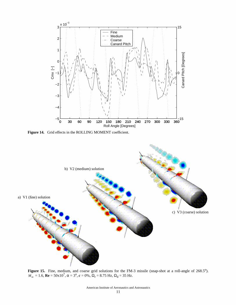
The rolling moment(Cmx) is shown in Figure14.As expected,the momentsare small. The differencebetweenthe V1 andV2 roll-averagedrolling momentsare approximately0.03% of the maximum pitchingmomentduringa revolution. A steady-statefreely spin-ning missileshouldhave anaveragedrolling momentofzero. Theoverall patternhereis in fair agreement,butthe detailsdiffer significantly. The rolling momentissensitive to flow detailsaroundthe tail fins, with com-plex interactionsbetweentheboundarylayer, thecanardvortices and the shocks,which again dependon theaccuratepredictionof the flow alongthe entiremissile.Grid convergencefor so small a quantityasthe rollingmoment is beyond the capacityof the presentset ofgrids.
Theeffectof grid resolutionon thepredictionof theaerodynamicdetailsof the flow is illustratedin Figure15. Figures15a,15b, and 15c provide a comparativeview of the canardvorticesandmissileboundarylayerinteractionvia plotsof helicity density(i.e., dot productof the velocity andvorticity vectors)at several stationsalongthelengthof themissile(for a roll-angleof 268.5o
at maximumnegative canarddeflection). The positionof thevorticesarein goodagreementfor theV1 andV2solutions. However, the vortex strengthis weaker andinteractionsbetweenthe inboardcanardvortex andvis-cousboundarylayerof themissilebodyarelessappar-ent in the V2 solution. The V3 solution differssignificantly from the V1 and V2 solutions in vortexposition, strength,and vortex/boundarylayer interac-tion.
Thegrid refinementresultssuggestvery goodover-all agreementbetweentheV1 andV2 solutions,thoughsomedifferencesareapparent.Still, theV2 grid offersagoodcompromisebetweensolutionaccuracy andsolu-tion throughputfor computationsdesignedto predictaerodynamicforcesandmoments.As notedabove,gridconvergenceof all forces and moments(except axialforce and rolling moment) are obtained.
4.2 Viscous Effects
A comparative evaluation of very high resolutionNavier-Stokes and Euler simulationsis usedto deter-mine the relative significanceof viscouseffectsopera-tive in the rangeof flight conditionsconsideredfor theFM-3 missile. The caseconditionsdefinedin Table1aretakenasrepresentative of theseflight conditions. Astatic FM-3 caseis first consideredwhere the missileroll-rateis zeroandthecanardsarefixedin neutralposi-
0 30 60 90 120 150 180 210 240 270 300 330 360−0.4
−0.2
0
0.2
0.4 Yawing Moment Coefficient − Cg
−Roll Angle [Degrees]
Cm
z [−
]
0 30 60 90 120 150 180 210 240 270 300 330 360−15
0
15
Can
ard
Pitc
h [D
egre
es]
FineMediumCoarseCanard Pitch
Figure 13. Grid effects in the YAWING MOMENT coefficient.
American Institute of Aeronautics and Astronautics
11
0 30 60 90 120 150 180 210 240 270 300 330 360−5
−4
−3
−2
−1
0
1
2
3x 10
−3 Rolling Moment Coefficient
−Roll Angle [Degrees]
Cm
x [−
]
0 30 60 90 120 150 180 210 240 270 300 330 360−15
0
15
Can
ard
Pitc
h [D
egre
es]
FineMediumCoarseCanard Pitch
Figure 14. Grid effects in the ROLLING MOMENT coefficient.
a) V1 (fine) solution
b) V2 (medium) solution
c) V3 (coarse) solution
Figure 15. Fine, medium,and coarsegrid solutionsfor the FM-3 missile (snap-shotat a roll-angle of 268.5o). = 1.6,Re = 50x107, α = 3o, c = 0%,Ωr = 8.75 Hz,Ωd = 35 Hz.M∞

American Institute of Aeronautics and Astronautics
12
tion. The fundamentaldifferencesbetweenstatic vis-cous and inviscid solutions are apparent and aregermaneto spinningcases. A spinningFM-3 missilewith ditheringcanardscaseis thenconsideredin detailfor a commandlevel of 0%, free-streamangle-of-attackof 3o, and missile roll-rate of 8.75 Hz.
The V1 solutionconsideredin Section4.1 is usedas the basisof comparisonfor a correspondinglyhighresolution inviscid simulation. The high resolutioninviscid, or “Euler grid,” is referredto hereafteras theE1 grid system.TheE1 surfacegridsandoff-body vol-umegrids are identicalwith the correspondingcompo-nents of the V1 grid system. The only differencesbetweentheE1 andV1 grids is thesurfacenormaldis-tribution of pointsin therespective near-bodygrid com-ponents. The E1 surface normal wall spacingis 20timesthatof theV1 grid. 33 million pointsareusedtodefinethecompleteE1 grid comparedto the41 millionpoints used in V1.
The computationalsavings available by assuminginviscid flow aresignificant. In thepresenthigh resolu-tion cases,20%fewergrid pointsareusedin theE1sys-tem than in the V1 system. Due to the larger surfacenormal wall-spacing,larger stable time-stepsare alsopossible− a ∆t increaseof 5 timesis usedin thepresentE1 simulations,allowing for nearly2,500stepspermis-sile revolution. In thepresentsimulations,thecombinedeffectsof fewer grid points,fewer floating-pointopera-tionsrequiredpergrid point,andlargertime-stepsresultin an order of magnitude savings in computationalexpense.
4.2.1 Static Geometry FM-3 CaseConsiderthe qualitative differencesbetweenvis-
cousand inviscid FM-3 missilesolutionsfor zeroroll-rateand neutralcanardpositioning. Thesedifferencescharacterizesomeof thetrendsthatareapparentfor thespinning missile and canard dithering conditions ofinteresthere. The vortex structureof the viscousandinviscid non-spinningFM-3 missilesolutionsareshownin Figure 16. The correspondingshockstructureandsurface pressuredistributions for the two casesareshown in Figures 17 and 18, respectively.
The position and strengthof the outboardcanardvortices are essentially identical in both solutions.However, theinboardcanardvorticesdiffer significantlyin both strengthandposition. Opposedby the viscousactionof theboundarylayer, theinboardcanardvorticesof theviscoussolutionareweaker andtraversea differ-ent path than their inviscid counterparts.The inboard
canardvortices (viscouscase)also pull the boundarylayer off the missile surface near the tail.
At the missile nose,the shockstructureis similarfor the viscousand inviscid solutions. The main fea-turesarea normalshockin front of thenose,anobliqueshockabove andbelow the nose,expansionaroundthetwo sharpcornersbetweennoseand fuselage,and theshocksin front of the canards. The local influenceofthe canard on the fuselage pressuredistribution issmearedsomewhat in the viscous case, due to theboundarylayer. The expansionand compressionoverthegroove is similarly weaker in theviscouscaseduetotheboundarylayer. At the tail, the interactionbetweentheboundarylayerandtheexpansion-wavesandshock-waves influences the pressure distribution significantly.
4.2.2 Dynamic Geometry FM-3 CaseConsider viscous and inviscid solutions for the
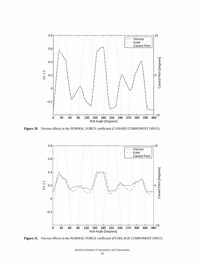
spinningFM-3 missile(Ωr = 8.75Hz andΩd = 35 Hz).The correspondingroll-averaged force and momentcoefficientsaregiven in Table3. Figure19 shows thenormalforcehistoriesover onerevolution. Theviscousand inviscid computationsagreewell, except at maxi-mum canarddeflection,where thereare instantaneousdifferencesof up to 20%. Theinfluenceof thedeflectedcanardsonoverall forcesappearmorepronouncedin theinviscid case,thoughthis is an indirect effect. Figures20, 21, and22 decomposethenormalforce into contri-butions from the canards,fuselage,and tail section,respectively. Thereis almostno differencebetweentheviscous and inviscid canard normal force historiesshown in Figure 20. The over prediction of normalforcesat maximumcanardanglesin the inviscid solu-tion are realizedfrom pressuredistribution differencesalongthefuselageandtail sections.Thevortex systemsshedfrom thecanardsinteractwith thefuselageandtailfins differently in the viscous and inviscid solutions.The inviscid inboardcanardvorticesare too energeticand positionedincorrectly, leading to the differencesseenin Figures21and22. Thesameeffectsaretrueforthe side forces shown in Figure 23.
Table 3. Roll-averaged force and moment coefs.*
Coefficient Viscous (V1) Inviscid (E1)Cx (axial) 1.17 1.10Cy (side) -7.56e-03 -19.6e-03Cz (normal) 0.461 0.449Cmx (roll) -1.19e-03 -1.65e-03Cmy (pitch) -6.79e-03 -1.06e-03Cmz (yaw) 2.80e-03 9.17e-03
*Moments are about the missile center of gravity

American Institute of Aeronautics and Astronautics
13
Figure 16. Vortical structure for static geometry FM-3 missile. = 1.6, Re = 50x107, α = 3o.M∞
viscous inviscid
viscous
inviscid
Figure 17. Shock structure for static geometry FM-3 missile. = 1.6, Re = 50x107, α = 3o.M∞

American Institute of Aeronautics and Astronautics
14
a) viscous
b) inviscid
c) d)viscous inviscid
Figure 18. SurfaceCpdistributionsfor staticgeometryFM-3 missile. = 1.6,Re = 50x107, α = 3o.M∞
0 30 60 90 120 150 180 210 240 270 300 330 360−0.2
0
0.2
0.4
0.6
0.8
1
1.2
1.4 Normal Force Coefficient
−Roll Angle [Degrees]
Cz
[−]
0 30 60 90 120 150 180 210 240 270 300 330 360−15
0
15
Can
ard
Pitc
h [D
egre
es]
ViscousEulerCanard Pitch
Figure 19. Viscous effects in the NORMAL FORCE coefficient.
American Institute of Aeronautics and Astronautics
15
0 30 60 90 120 150 180 210 240 270 300 330 360
−0.2
0
0.2
0.4
0.6
0.8 Normal Force Coefficient − Canards
Roll Angle [Degrees]
Cz
[−]
0 30 60 90 120 150 180 210 240 270 300 330 360−15
0
15
Can
ard
Pitc
h [D
egre
es]
ViscousEulerCanard Pitch
0 30 60 90 120 150 180 210 240 270 300 330 360
−0.2
0
0.2
0.4
0.6
0.8 Normal Force Coefficient − Fuselage
Roll Angle [Degrees]
Cz
[−]
0 30 60 90 120 150 180 210 240 270 300 330 360−15
0
15
Can
ard
Pitc
h [D
egre
es]
ViscousEulerCanard Pitch
Figure 20. Viscous effects in the NORMAL FORCE coefficient (CANARD COMPONENT ONLY).
Figure 21. Viscous effects in the NORMAL FORCE coefficient (FUSELAGE COMPONENT ONLY).

American Institute of Aeronautics and Astronautics
16
0 30 60 90 120 150 180 210 240 270 300 330 360
−0.2
0
0.2
0.4
0.6
0.8 Normal Force Coefficient − Tailfins
Roll Angle [Degrees]
Cz
[−]
0 30 60 90 120 150 180 210 240 270 300 330 360−15
0
15
Can
ard
Pitc
h [D
egre
es]
ViscousEulerCanard Pitch
Figure 22. Viscous effects in the NORMAL FORCE coefficient (TAILFIN COMPONENTS ONLY).
0 30 60 90 120 150 180 210 240 270 300 330 360−0.8
−0.6
−0.4
−0.2
0
0.2
0.4
0.6
0.8 Side Force Coefficient
−Roll Angle [Degrees]
Cy
[−]
0 30 60 90 120 150 180 210 240 270 300 330 360−15
0
15
Can
ard
Pitc
h [D
egre
es]
ViscousEulerCanard Pitch
Figure 23. Viscous effects in the SIDE FORCE coefficient.

American Institute of Aeronautics and Astronautics
17
The reasonthat the viscousand inviscid solutionsagreevery well everywhereexceptat maximumcanarddeflectionis evident in the vortical structuresshown inFigure24. Figure24ashows cuttingplaneswith helic-ity densitycontoursat several stationsalongthe lengthof the missile for a roll-angle of 61.5o. At this roll-angle,thecanardis in transitionbetweenthemaximumpositive andnegative canardpitch angles. Vorticestraileachcanardin counter-rotating pairs. Whenever thecanardssnapfrom positive to negative (or negative backto positive) pitch angle,therotationalsenseof thevorti-ces also reverse direction.
This effect is clearly evident in the instantaneoussnap-shotof the vortical field shown in Figure 24a.From the canarddownstreamto aboutthe missilemid-point, thevorticesbecomeweaker andfinally disappear.From the midpoint backto the tail section,the vorticesre-appearrotating in the oppositesenseand growingslightly in strength. Thehistoryof onetransitioncycleis capturedin this image. Vortex interactionwith theboundary layer is minimal during canard transition.Accordingly, the viscousand inviscid solutionsare invery good agreementfor all roll-angles where thecanards are in transition.
Figure24b shows cutting planeswith helicity den-sity contoursat several stationsalongthe lengthof the
missilefor a roll-angleof 84o. The instantaneoussolu-tion indicatedin the figure correspondsto the comple-tion of nearly20 degreesof missilerole, or 2.5 missilebody-lengthsof travel, with the canardspositionedatmaximum negative deflection. The fully developedcanardvorticesprevail well pastthemissile. Thevorti-cesinteractwith eachotherandwith theboundarylayer.Theinboardcanardvorticesareweakenedby thebound-ary layer, reducingtheforcepeaks,asseenin thenormaland side force histories of Figures 19 and 23. Theinboard canardvortex/boundarylayer interactionsareentirely unaccounted for in an inviscid simulation.
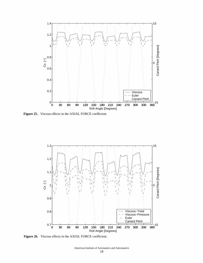
The roll-averagedaxial force for the viscoussolu-tion is about8% higherthanthecorrespondinginviscidsolution(seeTable3). Figure25 shows thecorrespond-ing axial force historiesover onerevolution. Approxi-mately60%of the differencenotedbetweentheviscousandinviscid axial force is dueto viscouswall stresses.The remaining40% of the differenceis due to spatialvariations in the surface pressuredistributions. Thepressurecontribution to axial force in the viscoussolu-tion is comparedseparatelyin Figure26 with the invis-cid axial force. Boundarylayer/shockinteractionsintheviscoussolutionleadto differencesin overall shockstructureandsurfacepressuredistributions,accountingfor these differences.
a) Canard transitionθ = 61.5o
b) Maximum negative canard deflection,θ = 84o
Figure 24. Vortical structurefor vsicousFM-3 spinningmissilecase. = 1.6, Re = 50x107, α = 3o, c = 0%,Ωr = 8.75 Hz,Ωd = 35 Hz.
M∞
American Institute of Aeronautics and Astronautics
18
0 30 60 90 120 150 180 210 240 270 300 330 3600
0.2
0.4
0.6
0.8
1
1.2
1.4 Axial Force Coefficient
−Roll Angle [Degrees]
Cx
[−]
0 30 60 90 120 150 180 210 240 270 300 330 360−15
0
15
Can
ard
Pitc
h [D
egre
es]
ViscousEulerCanard Pitch
0 30 60 90 120 150 180 210 240 270 300 330 3600.7
0.8
0.9
1
1.1
1.2
1.3 Axial Force Coefficient
−Roll Angle [Degrees]
Cx
[−]
0 30 60 90 120 150 180 210 240 270 300 330 360−15
0
15
Can
ard
Pitc
h [D
egre
es]
Viscous−TotalViscous−PressureEulerCanard Pitch
Figure 25. Viscous effects in the AXIAL FORCE coefficient.
Figure 26. Viscous effects in the AXIAL FORCE coefficient.

American Institute of Aeronautics and Astronautics
19
Figure 27 shows the pitching moment about themissile center of gravity. The viscous solution hashigherpeaks.Thestrongervorticesin theinviscid solu-tion interact with the fuselageand tail fins, adding amomentthat counteractsthe momentfrom the canards.A similar effect canbe seenfor the yawing momentinFigure 28.
Based on the high resolution viscous (V1) andinviscid (E1) simulations,a few statementsregardingtherelativesignificanceof viscouseffectsonFM-3 mis-sile performance are justified.
i. Instantaneousside-andnormalforcesdiffer upto 20%.This is dueto differencesin interactionbetween the vortex system shed from thecanardsand the fuselageboundarylayer andtail fins.
ii. The axial forcesdiffer by about8%. The vis-couswall stressesaccountsfor 60%of this dif-ference.
iii. Euler computationsprovide valuableinforma-tion, but viscous effects should ideally beincluded in detailed studies.
4.3 Roll-Rate Effects
An importantobjective in consideringtheutility ofcomputationalmethods(and physical experiments)forrolling airframemissilesystemsis the accuratepredic-tion of roll-averagedforces and moments. A largeparameterspacecan easily exhaustcomputational(orexperimental)resources,making it important to elimi-nateparametersof secondaryimportance.Thespinningmissilecasesdefinedin Table1 have a roll-rateof 8.75Hz, which allows for only 8o of missileroll per body-length of travel. It seemsplausible that for a givenpitching sequenceand moderateangularvelocity, theroll-averagedforces may not be sensitive to roll-rate.The relative significance of roll-rate effects in thisregime are determinedhere by evaluating differencesbetweensolutionshaving roll-ratesof zeroand8.75Hz.Thebaselineflight conditionsdefinedin Table1 andtheV2 grid systemareusedin all cases.The canardcom-mandlevel is 0% andthe free-streamangle-of-attackis3o.
The 8.75 Hz spinningmissile caseis discussedatlengthin Section4.1 andresultsusingtheV2 grid sys-temaregivenin Table2 andFigures7 through15. The“zero” roll-rate casesconsideredin the presentsectionfor comparative purposesare generatedin a discretequasi-staticfashionfor the sameroll-angle and canarddither cycle. The quasi-staticresultsfor the zero roll-
rate condition can be obtainedin one of several ways.Two obvious ways are as follows.
i. Staticgeometry. Startwith thedesiredmissileroll and canard pitch angles fixed in free-streamconditions. Drive the correspondingsolution to convergencein steady-statemode.Switch to time-accuratemode (static geome-try) andcontinuethesolutionto determinethetemporal state of the flow.
ii. Frozengeometry. Freezethe geometryof the8.75 Hz spinning caseat the desiredmissileroll andcanardpitchangles.Initialize thesolu-tion with thecorrespondinginstantaneousspin-ning result obtainedpreviously (see Section4.1). Hold the roll and canardpitch anglesconstant and run the simulation time-accu-ratelyuntil thefalse-transientdiesandto deter-mine the temporal state of the flow.
Figure 29 shows the time-history of the normalforcethatresultsfrom the“staticgeometry”and“frozengeometry”approachescorrespondingto a roll-angleof150o and-6.95o canardpitch angle. The normal forcecoefficient is plotted versus “relative” time-step,becauseboth steady-stateandtime-accurateintegrationareusedduringtheconvergencehistories. For thestaticgeometrycase,the solution is run to convergenceinsteady-statemode. At relative time-stepzero,the time-integration schemeis switchedto time-accuratemodeandrun furtherasshown. In all, morethan15,000time-stepsareneededto obtainaconvergedsolutionwith thisapproach.Thenumberof time-steps(or iterations)canbe reducedwith alternative integration schemes(e.g.,dual time-stepping,multigrid, etc.),but theeffort is stilla significantfractionof thecostof computinga full rev-olution for a dynamic case.
In the frozengeometryresult shown in Figure29,the instantaneoussolution from the spinning missilecaseis usedfor initial conditions. At relative time-stepzero, the missile orientationis frozen to the identicalstateusedwith the static geometryapproachand thesolutionis commencedtime-accurately. Cz quickly set-tles(in lessthan500steps)to a valuethat is identicaltothe Cz obtained from using the static geometryapproach. Time histories for the other forces andmomentsshow similar behavior. A comparisonof thetwo methods can be summarized as follows:
i. The two methodsprovide the sameresultsforforces and moments.
ii. A restartfrom thedynamicflow-field providesa steady-statesolution at least20 times fasterthan starting from scratchfor this particularroll-rate.

American Institute of Aeronautics and Astronautics
20
0 30 60 90 120 150 180 210 240 270 300 330 360−0.4
−0.2
0
0.2
0.4 Pitching Moment Coefficient
−Roll Angle [Degrees]
Cm
y [−
]
0 30 60 90 120 150 180 210 240 270 300 330 360−15
0
15
Can
ard
Pitc
h [D
egre
es]
ViscousEulerCanard Pitch
Figure 27. Viscous effects in the PITCHING MOMENT coefficient.
0 30 60 90 120 150 180 210 240 270 300 330 360−0.3
−0.2
−0.1
0
0.1
0.2
0.3 Yawing Moment Coefficient
−Roll Angle [Degrees]
Cm
z [−
]
0 30 60 90 120 150 180 210 240 270 300 330 360−15
0
15
Can
ard
Pitc
h [D
egre
es]
ViscousEulerCanard Pitch
Figure 28. Viscous effects in the YAWING MOMENT coefficient.

American Institute of Aeronautics and Astronautics
21
iii. Even if the problem turns out to be quasi-steady, it is more efficient to run through adynamiccomputationratherthancomputingaseries of static solutions.
The differencebetweenthe frozengeometryinitialsolution and the converged static geometry solutiondirectly shows thepoint-wiserelative effect of roll-rate.Figure 30 shows a comparisonof 6 static solutions(obtainedvia the frozengeometrymethod)to the time-accuratesolution for the 8.75 Hz spinningcase. Thecorrespondingstatic and dynamic resultsare in goodagreement.For roll angles30o, 90o, 210o and270o, thedynamicresultslag thestaticresultsby a few degreesofroll angle. For theroll angles150o and330o, thecanardis in the middle of a canard"snap" betweenthe twoextreme deflections. This causesa dynamic infloweffect,with botha delayandlargerchangesof forcesonthecanardsthanwhat is sustainedin a staticconfigura-tion of the missile. At 150o roll angle,the force over-shootoutweighsthe lag effect, and shifts the dynamicsolution aheadof the static solution. At a roll angle330o, the effects seem to cancel.
The other forces and moments (except rollingmoment)show similar behavior. The rolling momentsdiffer significantly. This is not surprising,sincetheroll-ing momentis generatedby the tail fins for which the
vorticity dynamicsbecomesignificant. Since the V1,V2, andV3 grid resolutionstudydoesnot demonstrateconvergencefor therolling moment,ananalysisof roll-rate effects on rolling moment is not attempted here.
In a studyof thesignificanceof roll-rateeffectsontheFM-3 missileaerodynamics,six datapointscanonlygiveanindicationof thecompletephenomenon.Still, itseemsplausiblethatmoderatechangesof roll-ratein therangeof 0 - 10Hz shouldnotaffect roll-averagedforcessignificantly.
4.4 Computational Expense
TheFM-3 missilecasesconvergeto a periodicallyrepeatingsolution in approximately460o of roll. Thecomputationalexpenseof eachV2 time-accuratesolu-tion is approximately438 hoursof CPU time on a 300MHz processor(viz., SGI Origin 2000)per revolution,or 560CPUhourspercase.Most of theV2 resultspre-sentedin this paperarethe resultof runsusing16 pro-cessors,with a processingrateof 35 hourspercaseandapproximately 95% parallel efficiency.
TheOVERFLOW-D performanceraterealizedforthe V2 solutionsjustifies the contemplationof aerody-namic databasepopulation with Navier-Stokes solu-tions. Maximumparallelefficiency percaseis realized
−15000 −10000 −5000 0 50000.5
0.6
0.7
0.8
0.9
1
1.1
1.2
1.3
1.4
1.5 Normal Force Coefficient
Relative Time Step
Cz
[−]
Static case, time accurate from step 0Restart from dynamic case, time accurate and frozen from step 0
Figure 29. NORMAL FORCEcoefficient. Comparisonof “static geometry”and“frozen geometry”approachestogeneratingquasi-staticsolutionsfor rolling airframemissiles. Staticgeometryconvergedin steady-statemodeuntilstep 0, then run time-accurately. Frozen geometry case run time-accurately from spinning missile initial condition.
Static Geometry − steady-state convergence historyFrozen Geometry − time-accurate

American Institute of Aeronautics and Astronautics
22
when the minimum number of processorsthat willaccommodatethe casein core memory is used. Fourprocessorsaresufficient for theV2 solutions(assuming1 gigabyte of memory per processor). Simultaneouscomputationof multiple casesleadsto perfectparallel-ism in the generationof solutionsets. For example,a256 nodeSGI Origin 2000canexecute64 FM-3 casessimultaneouslyyielding a throughputof approximately330casespermonth. A databasepopulatedby conven-tional means (i.e., physical experiments) does notrequiremany more points than this. For a rolling air-frame, suchas the FM-3, approximately600 spinningmissile datapoints is sufficient for a parameterspacethat includesMach number, angle-of-attack,commandlevel, and roll-rate.
5. AERODYNAMIC PERFORMANCE
5.1 Simulation Results
Given an understandingof the grid resolutionrequirementsandtherelativesignificanceof viscousandroll-rateeffects,a matrix of casesis definedto evaluatethe aerodynamicperformanceof the FM-3 spinningmissile subject to variations in free-streamangle-of-attack(α) andcanardcommandlevel (c). Thebaselineconditionsfor the casematrix aredefinedby the fixedparametersof Table1 ( , Re, andΩd) andwith the
roll-rate (Ωr) setto 8.75Hz. Thematrix consistsof 21uniquecasesdefinedby varyingα andc over therangesindicatedin Table1 (viz., α = 0o, 2o, 3o, 4o, 8o, 12o, 15o
andc = 0%,100%,200%). Thepitchingsequencesthatresultfrom the threecommandlevelsareshown in Fig-ure 31.
The results given in Section 4 demonstratethatalthough inviscid computationscan provide valuableinformationaboutthe FM-3 spinningmissile,therearesignificantviscouseffects(e.g.,fuselageboundarylayerdampingof theinboardcanardvortex). Theresultsalsoindicate that the mediumresolutionviscousgrid (V2)yields comparableresultsto the 41 million point base-line viscousgrid (V1). Accordingly, the casematrixconsideredhereis populatedentirelywith viscoussolu-tionsusingtheV2 grid system.Theresultsof Section4also suggestthat roll-rate effects are not importantfortheparameterspaceof interesthere. However, thecostof generating21 time-accuratespinning missile solu-tions to populatethe casematrix is far lessexpensivethan generatinga comparabledata basecomposedofquasi-staticsolutions. Time-accuratesimulationdataistherefore used.
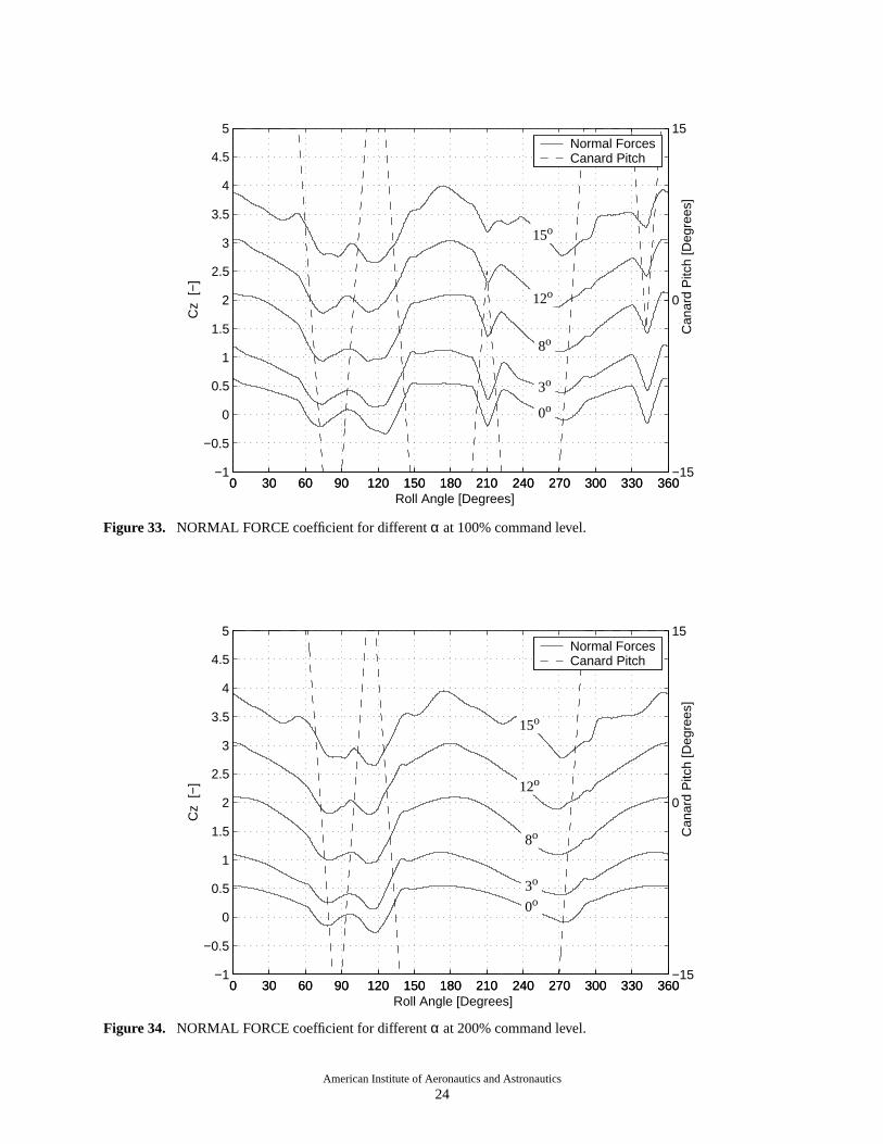
The normal forcesfor the 7 caseswith commandlevel 0% are shown in Figure 32. The correspondingresults for the 100% and 200% commandlevel areshown in Figures 33 and 34, respectively. Results forM∞
0 30 60 90 120 150 180 210 240 270 300 330 360−0.5
0
0.5
1
1.5 Normal Force Coefficient
− Roll Angle [Degrees]
Cz
[−]
0 30 60 90 120 150 180 210 240 270 300 330 360−1
0
1
Can
ard
Pitc
h [−
]
DynamicStaticCanard Pitch
Figure 30. Roll-rate effects in NORMAL FORCE coefficient.

American Institute of Aeronautics and Astronautics
23
0 30 60 90 120 150 180 210 240 270 300 330 360−20
−15
−10
−5
0
5
10
15
20
Canard Pitching Sequences
Roll Angle [Degrees]
Can
ard
Pitc
h A
ngle
[Deg
rees
]
0 % Command Level100 %200 %
0 30 60 90 120 150 180 210 240 270 300 330 360−1
−0.5
0
0.5
1
1.5
2
2.5
3
3.5
4
4.5
5 Normal Force Coefficient for α=0,3,8,12 and 15 degrees
− Roll Angle [Degrees]
Cz
[−]
0 30 60 90 120 150 180 210 240 270 300 330 360−15
0
15
Can
ard
Pitc
h [D
egre
es]
Normal ForcesCanard Pitch
Figure 32. NORMAL FORCE coefficient for differentα at 0% command level.
15o
0o
3o
8o
12o
Figure 31. Canard pitching sequences for 0%, 100%, and 200% command level.
American Institute of Aeronautics and Astronautics
24
0 30 60 90 120 150 180 210 240 270 300 330 360−1
−0.5
0
0.5
1
1.5
2
2.5
3
3.5
4
4.5
5 Normal Force Coefficient for α=0,3,8,12 and 15 degrees
Roll Angle [Degrees]
Cz
[−]
0 30 60 90 120 150 180 210 240 270 300 330 360−15
0
15
Can
ard
Pitc
h [D
egre
es]
Normal ForcesCanard Pitch
0 30 60 90 120 150 180 210 240 270 300 330 360−1
−0.5
0
0.5
1
1.5
2
2.5
3
3.5
4
4.5
5 Normal Force Coefficient for α=0,3,8,12 and 15 degrees
Roll Angle [Degrees]
Cz
[−]
0 30 60 90 120 150 180 210 240 270 300 330 360−15
0
15
Can
ard
Pitc
h [D
egre
es]
Normal ForcesCanard Pitch
Figure 34. NORMAL FORCE coefficient for differentα at 200% command level.
Figure 33. NORMAL FORCE coefficient for differentα at 100% command level.
15o
0o
3o
8o
12o
15o
0o3o
8o
12o

American Institute of Aeronautics and Astronautics
25
the 2o and 4o angle-of-attackfall smoothly betweenneighboringdatapoints,andareomitted in the figuresfor clarity. Theeffect of increasedα at eachcommandlevel is a shift of thenormalforcecurvesupwards,witha limited changein variationwith roll-angle. Thedirectcontribution of the canardsto instantaneousnormalforcedominateall othersources.However, thefuselageandtail sectioncontributionsarenot insignificant(recallFigures20 through22). Still, the variation in fuselageandtail-sectioncontributionsto normalforcearea sec-ondary effect of canardposition and resulting vortex/body interaction.
The side forces for the 7 casesat 0% commandlevel areshown in Figure35. Again, resultsfor α = 2o
and4o areomitted for clarity. The effect of α hereislessclearthanfor the normalforce. An increaseof αincreasesthe variation of side force. An interestingresultapparentin Figure35 arenon-zerosideforcesatroll-anglesof 0o and 180o (canardshorizontal). This isdue to the induced circulation from the missile spininteractingwith theverticalcomponentof theupstreamvelocity vector. This is similar to theMagnuseffect ona spinning golf-ball.
The roll-averagednormal forcesareshown in Fig-ure 36 and, consistentwith the trend in Figures 32
through 34, increasewith commandlevel. The roll-averagedsideforcesareshown in Figure37. Theside-forces increasewith commandlevel. Further, at eachcommandlevel, thesideforcegoesfrom positive to neg-ative with increasingangle-of-attack. The negativeside-forceat high α is causedpartly by the Magnuseffect asmentionedearlier. For a rotatingcylinder, theKutta-Joukowski theorem can be evaluated as follows:
whereα is theangle-of-attack,Ω thecylinder spin-rate,L the cylinder length, and the speedof the free-streamflow. Theresultis shown in Figure37 for com-parison.
Theroll-averagedpitchingmomentsaboutthecen-ter of gravity areshown in Figure38. The increaseinpitchingmomentwith commandlevel is consistentwiththeincreasein normalforcefor thecanard.A changeincommand level to maneuver the missile affects thepitching moment in a similar manner for differentα.
Theroll-averagedyawing momentsaboutthecenterof gravity areshown in Figure39. Thenegative contri-bution from an increaseof commandlevel is consistentwith the increasein canardside-force. The effect of
(1)Cy 4 αΩLU∞--------sin–=
U∞
0 30 60 90 120 150 180 210 240 270 300 330 360−1.2
−0.8
−0.4
0
0.4
0.8
1.2 Side Force Coefficient
Roll Angle [Degrees]
Cy
[−]
0 30 60 90 120 150 180 210 240 270 300 330 360−15
0
15
Can
ard
Pitc
h [−
]
0 deg3 deg8 deg12 deg15 degCanard Pitch
Figure 35. SIDE FORCE coefficient for differentα at 0% command level.

American Institute of Aeronautics and Astronautics
26
0 5 10 150
0.5
1
1.5
2
2.5
3
3.5Normal Force Coefficient
Angle of Attack [Degrees]
Cz
[−]
0 % Command100 % Command200 % Command
0 5 10 15−0.25
−0.2
−0.15
−0.1
−0.05
0
0.05
0.1Side Force Coefficient
Angle of Attack [Degrees]
Cy
[−]
0 % Command100 % Command200 % CommandKutta−Joukowski
0 5 10 15−0.05
0
0.05
0.1
0.15
0.2Pitching Moment Coefficient (about half body−length)
Angle of Attack [Degrees]
Cm
y [−
]
0 % Command100 % Command200 % Command
0 5 10 15−0.03
−0.02
−0.01
0
0.01
0.02Yawing Moment Coefficient (about half body−length)
Angle of Attack [Degrees]
Cm
z [−
] 0 % Command100 % Command200 % Command
inducedcirculationseenon theside-forcehardlymodi-fies the yawing moment about the center of gravity,sinceit is relatively evenly distributedalongthemissilelength.
5.2 Interpolation of Results
The roll-averaged inertial-frame forces andmomentsaretheobjectof analysisin precedingsectionsof this paper. Indeed,theunsteadinessseenin instanta-neous results is primarily causedby motion of thecanards.However, comparisonbetweencanardmotionandresultingforcesandmomentsis complicatedby therotatingframework usedfor presentationof thepitchingsequence.It is not obvious, for example,that thecom-puted force in Figure 30 correspondsto the pitching
sequencein thesamefigure. Lookingat thethreepitch-ing sequencesin Figure31, it is not immediatelyclearwhat to expectof changesin roll-averagedforceswhenthecommandlevel is changed,andif thesechangescanbe modeled well by linear interpolation, for example.
A methodof classifyinga canardpitchingsequenceis proposedhere to aid in the understandingof com-putedresults,andto provide a tool for interpolationofroll-averaged forces and momentsbetweendifferentcommandlevels. Theapproachtakenis to deriveamea-sureof theaerodynamicforceon thecanardsasa func-tion of canardorientation,which is basicallythe sameapproachas using angle-of-attackto evaluatelift on a2D airfoil. Here,theforce(vector)is averagedover onemissilerevolution to representthemeanforcevectoron
Figure 36. Roll-AveragedNORMAL FORCE coeffi-cients for the Case Matrix.
Figure 37. Roll-AveragedSIDEFORCEcoefficientsforthe Case Matrix.
Figure 38. Roll-AveragedPITCHING MOMENT coef-ficients for the Case Matrix.
Figure 39. Roll-AveragedYAWING MOMENT coeffi-cients for the Case Matrix.

American Institute of Aeronautics and Astronautics
27
thecanards.As discussedearlier, thecanardforcesarenot the only contributors to changesin overall missileforces,but shouldbethebestsingle-parameterapproxi-mation.
Two cartesianright-handedco-ordinatesystemsareusedin the analysis.The x-y-z systemis in the inertialframe,with thex-axispointingnoseto tail, y-axispoint-ing to the side,and the z-axis pointing up (seeFigure40). The r-s-t systemis initially orientedas the x-y-zsystem,correspondingto horizontalcanardswith zeropitch. However, the r-s-t system rotates with thecanards. The movementof the r-s-t basisvectorsareevaluated as follows:
i. Thepitch axis is rotatedaroundthe inertialframe x-axis with the roll-angle.
ii. The basisvector is rotatedaroundthe new with the canard pitch angle.
iii. The basisvectoris computedasthe cross-product
The canardangle-of-attackvector, , is proposedin Equation2 as a single parameterapproximationforchangesin missileloadsdueto changesin canardcom-mand level.
is theupstreamvelocityvectorat themissileangle-of-attack,α. It hascomponents , , and in therotat-ing system.
The three terms in Equation 2 are:1 A direction vector normal to the canard.This
approximatesthe directionof the force actingon the canard.
2 A fraction of the dynamic pressure,varyingbetween0 and1. This reducestheforceon thecanard according to the local "side-slip" angle.
3 The local angle-of-attack in ther-s-t system
is a measureof the force acting on the canard,expressedas an angle-of-attack. The inertial framecomponentsof this vectoraredefinedasaxial, side,andnormal canard angles-of-attack (viz.,αcx, αcy, andαcz).
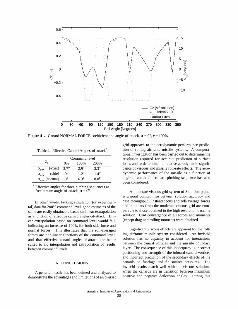
The “effective” canardangle-of-attackvector, ,is obtainedby averaging throughoneperiodof thepitching sequence.The inertial frame componentsofthis quantity are intendedto describethe effect of acanardpitching sequenceon the roll-averagedforces.Figure41 shows resultsfor a casefor α = 0o andcom-mandlevel 100%. Thesolid line is theCz obtainedfromtheV2 simulationresults(scaleshown on the left verti-cal axis). The dashedline is the canardnormalangle-of-attack, , computedfrom the pitching sequence(scaleshown on theright verticalaxis). Thedottedlineis the canardpitching sequence(scale shown on theright verticalaxis). Thescaleswerechosento show theexcellentcorrelationbetweenthe V2 simulationresultsandthe geometricquantity (canardnormalangle-of-attack). Theside-forceshows similar behavior. Thisindicatesthat thecanardangle-of-attackvectoris a use-ful estimator of forces on the canards.
The effective canard angles-of-attack(i.e., roll-averagedinertial frame componentsof ) for thethreecanardpitching sequencesat α = 0o are listed inTable4. Thesenumbersarecomputedfrom thepitch-ing sequencealone,andcanbeusedasa first guessfortrendsin roll-averagedforces. An increasein commandlevel gives mainly an increasein the effective normalcanard angle-of-attack( ), but also gives smallincreasesin and . Increasingthe commandlevel from 100%to 200%increasestheeffective normalcanard angle-of-attackby 27%. The correspondingincreasefor thecomputednormalforcefor theV2 solu-tion is also27%. Thecorrespondingnumbersfor effec-tive side canardangle-of-attackand V2 solution sideforce show increasesof 19% and 26%, respectively.Thesearealsoin reasonablygoodagreementconsider-ing that the side forces are small.
es
eres
eter es×
Figure 40. r-s-t rotating reference frame basis vecorsrelative to inertial frame x-y-z coordinate axes.
eres
et
x
z
y
αc
αc et
ur2
ut2
+
u u⋅----------------- sin
1–(
ut
ur2
ut2
+---------------------)= (2)
1 2 3
uur us ut
αc
αceαc
αcz
αcz
αc
αcezαcey αcex
American Institute of Aeronautics and Astronautics
28
0 30 60 90 120 150 180 210 240 270 300 330 360
−0.4
−0.2
0
0.2
0.4
0.6
Canard Normal Force Coefficient and Canard Normal Angle of Attack
Roll Angle [Degrees]
Cz
[−]
0 30 60 90 120 150 180 210 240 270 300 330 360
−10
−5
0
5
10
15
α cz[d
egre
es]
Cz (V2 solution)α
cz (Equation 2)
Canard Pitch
In other words, lacking simulation(or experimen-tal) datafor 200%commandlevel, goodestimatesof thesameareeasilyobtainablebasedon linearextrapolationasa functionof effective canardangles-of-attack. Lin-ear extrapolationbasedon commandlevel would fail,indicatingan increaseof 100%for both sideforce andnormal forces. This illustrates that the roll-averagedforcesare non-linearfunctionsof the commandlevel,and that effective canard angles-of-attackare bettersuited to aid interpolationand extrapolationof resultsbetween command levels.
6. CONCLUSIONS
A genericmissilehasbeendefinedandanalyzedtodemonstratetheadvantagesandlimitationsof anoverset
grid approachto the aerodynamicperformancepredic-tion of rolling airframemissile systems. A computa-tional investigationhasbeencarriedout to determinetheresolution required for accurateprediction of surfaceloadsandto determinetherelative aerodynamicsignifi-canceof viscousandmissileroll-rateeffects. Theaero-dynamic performanceof the missile as a function ofangle-of-attackand canardpitching sequencehasalsobeen considered.
A moderateviscousgrid systemof 8 million pointsis a good compromisebetweensolution accuracy andcasethroughput. Instantaneousandroll-averageforcesandmomentsfrom the moderateviscousgrid arecom-parableto thoseobtainedin thehigh resolutionbaselinesolution. Grid convergenceof all forcesandmoments(except drag and rolling moment) were obtained.
Significantviscouseffectsareapparentfor theroll-ing airframe missile systemconsidered. An inviscidsolution has no capacity to account for interactionsbetweenthe canardvorticesand the missile boundarylayer. The consequenceof this inadequacy is incorrectpositioningandstrengthof the inboardcanardvorticesandincorrectpredictionof the secondaryeffectsof thecanardson fuselageand fin surface pressures. Theinviscid resultsmatch well with the viscoussolutionswhen the canardsare in transitionbetweenmaximumpositive and negative deflection angles. During this
* Effective angles for three pitching sequences atfree-stream angle-of-attack,α = 0o.
αc
Command level0%2.7o
0o
0o
100%2.9o
1.2o
6.3o
200%3.3o
1.4o
8.0o
αcex
αcez
αcey
(axial)(side)
(normal)
Table 4. Effective Canard Angles-of-attack*
Figure 41. Canard NORMAL FORCE coefficient and angle-of-attack,α = 0o, c = 100%

American Institute of Aeronautics and Astronautics
29
interval, thecanardvorticesareof minimal strengthandthe inviscid flow approximation is good.
Variationof roll-ratein therangeof 0 to 10Hz doesnot have a significantaffect on roll-averagedforcesandmomentsfor theFM-3 missile. Theeffectson instanta-neousloadsarealsominimal. The effectsmanifestassmall roll-angle leads or lags in the load history.
A single parametermethodof approximationforchangesin missileloadsdueto changesin canardpitchanglecommandlevel is presented.The approximationmethodhelpsinterpretthephysicalsignificanceof sim-ulationresultsandprovidesa powerful tool for interpo-lation of resultsbetweenknown datapoints. As such,themethodis a quick andinexpensive meansof supply-ing missing data, or for database expansion.
An oversetstructuredgrid domain decompositionmethodenablesaccurateandefficientsimulationof roll-ing airframemissileconfigurationsthat involve relativemotion betweensystemcomponents.Casethroughputratesaresufficient to contemplateaerodynamicdatabasepopulationwith Navier-Stokes solutions. It is signifi-cantto notethattime-accuratesimulationfor onerollingairframecasewith OVERFLOW-D is muchlessexpen-sive than generatingthe samedata via correspondingquasi-staticsolutionsfor neededroll-anglesandcanardpitch positions. Eachquasi-staticsolution costsa sig-nificant fraction of a single time-accuraterolling air-frame solution. A combination of time-accuratesimulationsfor a relatively small numberof pitchingsequencesandthecanardangle-of-attackbasedapproxi-mation method representa powerful way to quicklypopulate a large aerodynamic data base.
ACKNOWLEDGEMENTSThe authorsgratefully acknowledge the contribu-
tionsof Mr. MichaelAftosmisandDr. ScottMurmanofNASA AmesResearchCenter. They provided help inconverting the FM-3 missilegeometrydefinition into ausefulformatandparticipatedwith theauthorsin manyhelpful andinterestingdiscussions.The expert consul-tationandassistanceprovidedby Mr. Mark Potsdamofthe U.S. Army Aeroflightdynamics Directorate atNASA Ames Research Center is also gratefullyacknowledged.This work was supportedin part by agrantof computertimefrom theDoD High PerformanceComputingModernizationProgramat the ARL MajorShared Resource Center.
REFERENCES
[1] Steger, J.,Dougherty, C.,andBenek,J.,“A ChimeraGrid Scheme,” Advancesin Grid Generation, K. N.Ghia and U. Ghia, eds.,ASME FED-Vol 5., June1983.
[2] Meakin, R., "Automatic Off-Body Grid Generationfor Domainsof Arbitrary Size,"AIAA-2001-2536,15th AIAA ComputationalFluid DynamicsConf.,June 2001, Anaheim, CA.
[3] Meakin, R., "Adaptive Spatial Partitioning andRefinementfor OversetStructuredGrids" Comput.Methods Appl. Mech. Engrg., Vol. 189 (2000),1077-1117.
[4] Chan,W., "The OVERGRID Interfacefor Computa-tional Simulationson OversetGrids" AIAA Paper2002-3188,32nd AIAA Fluid Dynamics Confer-ence, St.~Louis, Missouri, June, 2002.
[5] Chan,W., Meakin, R., and Potsdam,M., "CHSSISoftware for Geometrically Complex UnsteadyAerodynamic Applications," AIAA 2001-0539,AIAA 39thAerosciencesMeetingandExhibit, Jan-uary, 2001, Reno, NV.
[6] Buning, P. G., Jespersen,D. C., Pulliam, T. .H,Chan,W. M., Slotnick,J.P., Krist, S.E. andRenze,K. J., ‘‘OVERFLOW User’s Manual,’’ Version1.8,NASA Langley Research Center, 1998.