an advanced dark fiber monitoring system for next generation optical access...
TRANSCRIPT

Slide subtitle
An advanced Dark Fiber Monitoring
System for Next Generation Optical
Access Networks
Min Cen, Jiajia Chen, Véronique Moeyaert, Patrice Mégret
and Marc Wuilpart
18th Annual Workshop of the IEEE Photonics Benelux Chapter
Mons, Belgium, 2015-05-22

Slide title
Do not add objects or
Commercial in confidence | © Ericsson AB 2011 | 2011-03-25 | Page 2Min Cen| Service d'Electromagnétisme et Télécommunications, Faculté PolytechniqueUniversité de Mons Min Cen| Service d'Electromagnétisme et Télécommunications, Faculté Polytechnique
Outline
› Introduction
›Operation Principle
›Experimental validation
›Conclusions
1/16

Slide title
Do not add objects or
Commercial in confidence | © Ericsson AB 2011 | 2011-03-25 | Page 3Min Cen| Service d'Electromagnétisme et Télécommunications, Faculté PolytechniqueUniversité de Mons Min Cen| Service d'Electromagnétisme et Télécommunications, Faculté Polytechnique
Introduction
Next generation optical access (NGOA)
2/16
NGOA:
• cover large service
areas
• high-capacity
• support multi-service
environment
http://www.omnitron-systems.com/cpri-fronthaul/migrating-to-cloud-based-ran-fronthaul.php

Slide title
Do not add objects or
Commercial in confidence | © Ericsson AB 2011 | 2011-03-25 | Page 4Min Cen| Service d'Electromagnétisme et Télécommunications, Faculté PolytechniqueUniversité de Mons Min Cen| Service d'Electromagnétisme et Télécommunications, Faculté Polytechnique
Introduction
“Ring-and-Spur” Long-Reach PON
“Ring-and-Spur” Long Reach PON, a promising solution for NGOA
• Consolidation of metro and access networks, feeder fiber can be up
to 100 km
• Reduces the number of COs and active optical interfaces
3/16
C. M. Machuca, et al., IEEE Commun. Mag. vol. 50, no. 8, p.110-117 (2012)
A fault occurs: a large
amount of data will be
lost
Monitoring: real-time
information of fault
location

Slide title
Do not add objects or
Commercial in confidence | © Ericsson AB 2011 | 2011-03-25 | Page 5Min Cen| Service d'Electromagnétisme et Télécommunications, Faculté PolytechniqueUniversité de Mons Min Cen| Service d'Electromagnétisme et Télécommunications, Faculté Polytechnique
Introduction Optical Time Domain Reflectometry(OTDR)
4/16
OTDR[2]
Fiber under test
• P2P characterization
• Loss, RL, attenuation coef…
• 1m or 30m resolution
• 30-40 dB dynamic range
Limitations:
• Amplifiers on the ring can only work
on C-band, OTDR signals (U-band)
will be blocked
• Lack of dynamic range
• Long measurement time (3 minutes)
http://www.thefoa.org/tech/ref/quickstart/OTDR/
Optical Time Domain ReflectometryOTDR for LR-PON monitoring

Slide title
Do not add objects or
Commercial in confidence | © Ericsson AB 2011 | 2011-03-25 | Page 6Min Cen| Service d'Electromagnétisme et Télécommunications, Faculté PolytechniqueUniversité de Mons Min Cen| Service d'Electromagnétisme et Télécommunications, Faculté Polytechnique
Outline
› Introduction
›Operation Principle
›Experimental validation
›Conclusions
5/16

Slide title
Do not add objects or
Commercial in confidence | © Ericsson AB 2011 | 2011-03-25 | Page 7Min Cen| Service d'Electromagnétisme et Télécommunications, Faculté PolytechniqueUniversité de Mons Min Cen| Service d'Electromagnétisme et Télécommunications, Faculté Polytechnique
“Ring and Spur” LR-PON monitoring
Dark fiber monitoring scheme[3]
• Dark fiber monitoring
TRA: transmission reflection analysis
6/16
Dark fiber: fiber deployed in the same cable but not carry data
• Cover major faults
• One can choose any
monitoring λ, power
• No traffic interruption
M. Cen, et al, ECOC 2014
M. Cen, et al, OFC 2015
• Bi-directional multi-wavelength TRA (BD-nλ-TRA) approach

Slide title
Do not add objects or
Commercial in confidence | © Ericsson AB 2011 | 2011-03-25 | Page 8Min Cen| Service d'Electromagnétisme et Télécommunications, Faculté PolytechniqueUniversité de Mons Min Cen| Service d'Electromagnétisme et Télécommunications, Faculté Polytechnique
New monitoring techniques (1)
Transmission Reflection Analysis (TRA)[4]
7/16
[5] M. Cen, et al, Symposium IEEE Photonics Benelux Chapter, 2012, pp. 127-130[4] V.V.Spirin, IEEE PHOTONIC TECH. L. 16, 569 (2004)
Basic principle: It is based on the unique relationship between the transmitted
power (PT) and the backscattered power (PB) at a certain fault location[5]
1. Only for non-reflective events
(e.g. fiber bending) localization;
2. Low accuracy at remote end
SLD
SLD: super luminescent diode

Slide title
Do not add objects or
Commercial in confidence | © Ericsson AB 2011 | 2011-03-25 | Page 9Min Cen| Service d'Electromagnétisme et Télécommunications, Faculté PolytechniqueUniversité de Mons Min Cen| Service d'Electromagnétisme et Télécommunications, Faculté Polytechnique
New monitoring techniques (2)
Multi-wavelength (e.g., 2λ) -TRA (newly proposed)[6]
› 𝑅𝑛1 =𝑃𝐵λ1
𝑃𝐵01=
𝑅𝑟𝑎𝑦1 𝑧𝑝 +T12 𝑧𝑝 ∙𝑅𝐿+[𝑅𝑟𝑎𝑦1 𝐿 −𝑅𝑟𝑎𝑦1 𝑧𝑝 ]∙𝑡𝑛
2
𝑅ray1 𝐿
› 𝑅𝑛2 =𝑃𝐵λ2
𝑃𝐵02=
𝑅𝑟𝑎𝑦2 𝑧𝑝 +T22 𝑧𝑝 ∙𝑅𝐿+[𝑅𝑟𝑎𝑦2 𝐿 −𝑅𝑟𝑎𝑦2 𝑧𝑝 ]∙𝑡𝑛
2
𝑅ray2 𝐿 Rray1(2), T1(2) are
changed with λ
2 equations, 2
unknown variables (zp
and RL)
Able to localize reflective events
(e.g. fiber breaks)
8/16
OS
M. Cen, et al, OPTICS EXPRESS, Vol. 22, Issue 25, pp. 31248-31262 (2014)

Slide title
Do not add objects or
Commercial in confidence | © Ericsson AB 2011 | 2011-03-25 | Page 10Min Cen| Service d'Electromagnétisme et Télécommunications, Faculté PolytechniqueUniversité de Mons Min Cen| Service d'Electromagnétisme et Télécommunications, Faculté Polytechnique
New monitoring techniques (3)
Bi-Directional TRA (newly proposed)[7]
9/16
› 𝑅𝑛1 =𝑃𝐵1
𝑃𝐵01=
𝑅𝑟𝑎𝑦 𝑧𝑝 +𝑇2 𝑧𝑝 ∙𝑅𝐿+[𝑅𝑟𝑎𝑦 𝐿 −𝑅𝑟𝑎𝑦 𝑧𝑝 ]∙𝑡𝑛2
𝑅ray 𝐿
› 𝑅𝑛2 =𝑃𝐵2
𝑃𝐵02=
𝑅𝑟𝑎𝑦 𝐿−𝑧𝑝 +𝑇2 𝐿−𝑧𝑝 ∙𝑅𝐿+[𝑅𝑟𝑎𝑦 𝐿 −𝑅𝑟𝑎𝑦 𝐿−𝑧𝑝 ]∙𝑡𝑛2
𝑅ray 𝐿
Improve the
accuracy at
remote end
(Long-Reach)
M. Cen, et al, OPTICS EXPRESS, Vol. 22, Issue 8, pp. 9839-9853 (2014)

Slide title
Do not add objects or
Commercial in confidence | © Ericsson AB 2011 | 2011-03-25 | Page 11Min Cen| Service d'Electromagnétisme et Télécommunications, Faculté PolytechniqueUniversité de Mons Min Cen| Service d'Electromagnétisme et Télécommunications, Faculté Polytechnique
Localization Accuracy Analysis
simulation results
• Bi-directional configuration provides much better localization accuracy
at the remote end (localization error: from 5.3km to 0.1m; STD: from
15km to 5m)
10/16
Slide title
Do not add objects or
Commercial in confidence | © Ericsson AB 2011 | 2011-03-25 | Page 12Min Cen| Service d'Electromagnétisme et Télécommunications, Faculté PolytechniqueUniversité de Mons Min Cen| Service d'Electromagnétisme et Télécommunications, Faculté Polytechnique
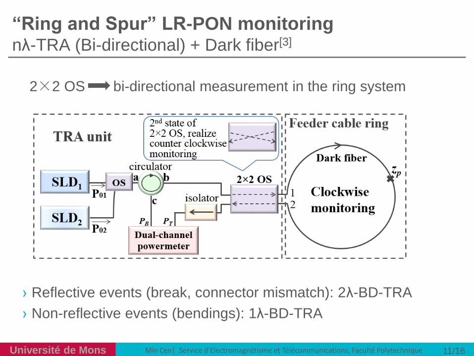
“Ring and Spur” LR-PON monitoring nλ-TRA (Bi-directional) + Dark fiber[3]
› Reflective events (break, connector mismatch): 2λ-BD-TRA
› Non-reflective events (bendings): 1λ-BD-TRA
11/16
2×2 OS bi-directional measurement in the ring system
Slide title
Do not add objects or
Commercial in confidence | © Ericsson AB 2011 | 2011-03-25 | Page 13Min Cen| Service d'Electromagnétisme et Télécommunications, Faculté PolytechniqueUniversité de Mons Min Cen| Service d'Electromagnétisme et Télécommunications, Faculté Polytechnique
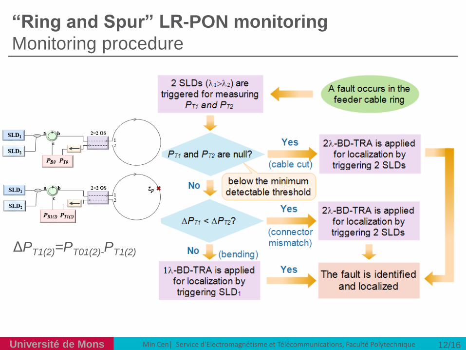
“Ring and Spur” LR-PON monitoring
Monitoring procedure
12/16
ΔPT1(2)=PT01(2)-PT1(2)

Slide title
Do not add objects or
Commercial in confidence | © Ericsson AB 2011 | 2011-03-25 | Page 14Min Cen| Service d'Electromagnétisme et Télécommunications, Faculté PolytechniqueUniversité de Mons Min Cen| Service d'Electromagnétisme et Télécommunications, Faculté Polytechnique
Outline
› Introduction
›Operation Principle
›Experimental validation
›Conclusions
13/16

Slide title
Do not add objects or
Commercial in confidence | © Ericsson AB 2011 | 2011-03-25 | Page 15Min Cen| Service d'Electromagnétisme et Télécommunications, Faculté PolytechniqueUniversité de Mons Min Cen| Service d'Electromagnétisme et Télécommunications, Faculté Polytechnique
Zp1 [km] Zp2 [km] Zp3 [km] Zp4 [km] Zp5 [km]
OTDR 0 1.727 26.42 51.13 56.02
TRA -0.0015 1.7264 26.4454 51.1227 56.026
Difference 1.5m <1m 25.4m 7.3m 6m
Experimental validation Comparison between OTDR and 2λ BD-TRA
Case of fiber break (2λ-BD-TRA, 1550nm+1310nm):
Zp1 [km] Zp2 [km] Zp3 [km] Zp4 [km] Zp5 [km]
OTDR 0 1.727 26.42 51.13 56.02
TRA 0.015 1.7237 26.4306 51.1233 56.002
Difference 15m 4.3m 10m 6.7m 18m
Case of fiber bending (1λ-BD-TRA, 1550nm):
L [km]: 56.02; zp [km]:0, 1.727, 26.42, 51.13, 56.02;
Event: fiber break, fiber bending
14/16

Slide title
Do not add objects or
Commercial in confidence | © Ericsson AB 2011 | 2011-03-25 | Page 16Min Cen| Service d'Electromagnétisme et Télécommunications, Faculté PolytechniqueUniversité de Mons Min Cen| Service d'Electromagnétisme et Télécommunications, Faculté Polytechnique
OTDR nλ BD-TRA
Measurement time 3 minutes 3 seconds
Spatial resolution 30m1m(best)/60m(worst)
1m(best)/20m(worst)
Light source Time modulated Unmodulated CW
Dynamic range <45dB >60dB
Comparison between OTDR and nλ BD-TRA
Discussion
Comparison between OTDR and nλ-BD-TRA for the LR-PON
monitoring:
15/16
nλ BD-TRA provides better localization
performance than OTDR

Slide title
Do not add objects or
Commercial in confidence | © Ericsson AB 2011 | 2011-03-25 | Page 17Min Cen| Service d'Electromagnétisme et Télécommunications, Faculté PolytechniqueUniversité de Mons Min Cen| Service d'Electromagnétisme et Télécommunications, Faculté Polytechnique
Conclusion:
› Able to identify and localize a single event along the feeder ring
› The dark fiber concept one can choose any monitoring
wavelength; Monitoring can be performed without any traffic
interruption
› Newly proposed TRA based technique greatly save the
monitoring time (from a few min to a few seconds); improve the
dynamic range (>60dB); requires simpler light source
Conclusion and future works
16/16
A fast and simple monitoring
solution for LR-PON system
Future works:
› Cover distribution section monitoring

Slide title
Do not add objects or
Commercial in confidence | © Ericsson AB 2011 | 2011-03-25 | Page 19Min Cen| Service d'Electromagnétisme et Télécommunications, Faculté PolytechniqueUniversité de Mons Min Cen| Service d'Electromagnétisme et Télécommunications, Faculté Polytechnique
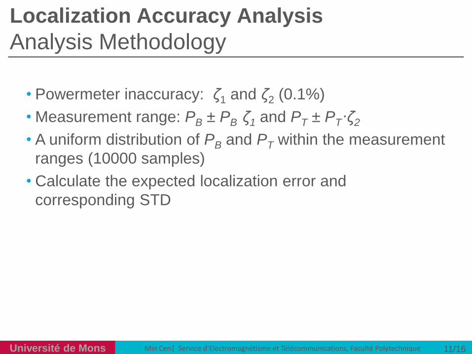
Localization Accuracy Analysis
Analysis Methodology
11/16
• Powermeter inaccuracy: ζ1 and ζ2 (0.1%)
• Measurement range: PB ± PB·ζ1 and PT ± PT·ζ2
• A uniform distribution of PB and PT within the measurement
ranges (10000 samples)
• Calculate the expected localization error and
corresponding STD

Slide title
Do not add objects or
Commercial in confidence | © Ericsson AB 2011 | 2011-03-25 | Page 20
Université de Mons Min Cen| Service d'Electromagnétisme et Télécommunications, Faculté Polytechnique
ΔPT comparison
› the bending loss is mainly caused by the fiber refractive
index distortion. The shorter the wavelength, the better the
optical mode confinement in the fiber. Therefore light with
shorter wavelength will lead to a smaller ΔPT. In opposite,
regarding a connector mismatch (perpendicular to the fiber
axis) whose loss is related to the mode filed diameter
(MFD), light with shorter wavelength will generate a larger
ΔPT.

Slide title
Do not add objects or
Commercial in confidence | © Ericsson AB 2011 | 2011-03-25 | Page 21
Université de Mons Min Cen| Service d'Electromagnétisme et Télécommunications, Faculté Polytechnique
Connector mismatch
› It should be noted that the functionality of detecting and
localizing a connector mismatch in a dark fiber is not
dedicated to the monitoring of the data carrying fibers. By
analyzing the transmitted power, one can identify whether
the detected fault is shared among all the data carrying
fibers (cutting, bending) or not (connector mismatch).
Based on this information, the operator could proceed
forward, either by localizing the cable cut or bending for the
data carrying fibers or by fixing the dark fiber connection at
the localized location. Moreover, with the increased
bandwidth demand, the dark fibers deployed in the cable
may be used for data transmission fiber in future. With this
in mind, it is important to evaluate the quality of the dark
fiber before using it for data transmission.