an abstract of the thesis of title: an internal convective
TRANSCRIPT
AN ABSTRACT OF THE THESIS OF
Sumantra Bose for the degree of Master of Science in Industrial Engineering
presented on September 25, 2008.
Title: An Internal Convective Heating Technique for Diffusion Bonding Highly Parallel
Microchannel Architectures
Abstract approved:
_____________________________________________________________________
Brian K. Paul
Diffusion bonding cycle times can be a large cost factor in the production of metal
microchannel devices. The challenge is to significantly minimize this cost by reducing
the bonding cycle time through rapid and uniform heating and cooling within the bonding
process. Heating rates in diffusion bonding processes are typically limited by the need to
minimize internal thermal gradients during bonding. A novel method is described which
takes advantage of the internal flow passages within microchannel devices for convective
heat transfer during the bonding process. The internal convective heating (ICH) technique
makes use of heated inert gas to provide the microchannel assembly with rapid and
uniform heat input. The first paper in this thesis manuscript investigates the feasibility of
the ICH method by studying leakage rates and thermal requirements within the process.

The second paper provides results and a statistical analysis demonstrating that the ICH
technique is feasible and capable of shorter bonding cycle times than traditional vacuum
hot press methods. Results suggest that this may be due to smaller thermal gradients
within microchannel devices during the ICH bonding cycle. Appendices are provided at
the end of this manuscript providing the raw data to support these findings.

An Internal Convective Heating Technique for Diffusion Bonding Highly Parallel
Microchannel Architectures
by
Sumantra Bose
A THESIS submitted to
Oregon State University in partial fulfillment of the requirements for the
degree of Master of Science
Presented September 25, 2008 Commencement June 2009

Master of Science thesis of Sumantra Bose presented on September 25, 2008. APPROVED: _____________________________________________________ Major Professor representing Industrial Engineering _____________________________________________________ Head of the School of Mechanical, Industrial & Manufacturing Engineering _____________________________________________________ Dean of the Graduate School
I understand that my thesis will become part of the permanent collection of Oregon
State University libraries. My signature below authorizes release of my thesis to any
reader upon request.
_________________________________________________________
Sumantra Bose, Author

ACKNOWLEDGEMENTS I would like to express my sincere thanks to my advisor, Dr. Brian K. Paul, for giving me
the opportunity to pursue my graduate studies at Oregon State University under his
valuable guidance. I had the wonderful experience of working with him on one of the
most upcoming technologies in modern day engineering.
My appreciation is extended to Dr. Daniel R. Palo (PNNL), who had provided me with
all the support and guidance that was needed throughout my tenure at the university. I
would also like to greatly appreciate the efforts of Benjamin Roberts (PNNL), for
providing immense help in the setup of my experiments.
Specially, I would like to thank Dr. Sundar V. Atre, for serving as my minor professor in
Manufacturing Engineering and guiding me through some of my graduate coursework.
My appreciation is extended to Mr. Steve Etringer, for his valuable machining work and
assistance in my research activities at Oregon State University. I would also like to thank
Todd Miller and Jack Rundel, who were always supportive of my experimental work at
ONAMI (B11), along with providing valuable tips and insights.
I am also especially thankful for the encouragement and assistance of all my fellow
graduate students who made the experience of studying abroad unique and enjoyable.
Most of all, I would like to express gratitude and love to my parents, family, and friends,
for supporting me throughout and helping me overcome the hurdles along the way.
TABLE OF CONTENTS
Chapter Page
Chapter 1 - Introduction …………………………………………… 1
Chapter 2 - Leakage rates and thermal requirements for the
diffusion bonding of microchannel arrays
via internal convective heating ………………………… 4
Chapter 3 - An internal convective heating system for
diffusion bonding highly parallel
microchannel architectures ………… …………………. 21
1. Introduction …………………………………………. 21
2. Experimental approach………………………………… 25
2.1 Thermal load and distribution…………………… 27
2.2 Platen assembly design…………………………. 30
2.2.1 Microchannel Test Article…………... 30
2.2.2 Platen Assembly…………………… 31
2.2.3 Leakage Tests………………………… 31
2.2.4 Final ICH Test Setup………………… 34
2.3 Experimental design……………………………. 36
2.4 Experimental Protocol………………………. 37
2.4.1 Pre bonding protocol………………… 37
2.4.2 In process Protocol…………………... 38
2.4.3 Post bonding protocol………………. 39
3. Results and discussion………………………………… 41

TABLE OF CONTENTS (Continued)
Page
4. Conclusions and Future work………………………… 46
Chapter 4 - Summary……………………………………………………. 48
Appendices……………………………………………………………….. 50
Bibliography………………………………………………………………. 94
LIST OF FIGURES Figure Page 1.1 Classification of microfluidic devices:
(left) analytical microfluidics also known as micro total analysis systems; and (right) arrayed microfluidics also known as micro energy and chemical systems................................................................................ 5
2.1 Comparison of cycle time on VHP and ICH……………….... 7 2.2 Simplified schematic of an internal convective heating setup 8 2.3 Assembly of platens and laminae.………………………….. 9 2.4 Bonded platens with shims ………………………………… 10 2.5 Schematic of leakage test setup ……………………………. 11 2.6 Leakage vs Clamping pressure with varying back pressure… 13 2.7 Leakage vs clamping pressure with boron nitride coating….. 14 2.8 Exploded view of INC 625 heat exchanger………………….. 15 2.9 Gas temperature as a function of distance in heat exchanger.... 19 2.10 Temperature distribution of argon in the channel……………. 19 3.1 Schematic of microlamination approach………………… 22 3. 2 Progression of void elimination within a typical
diffusion bonding cycle…………………………………… 23
3.3 Cycle time comparison of diffusion bonding cycles in a vacuum hot press (VHP) showing slow ramp rates and using internal convective heating showing fast ramp rates….…….……….. 24
3.4 Conceptual ICH diagram with thermocouple placements and PID loop…………………………………... 25
3.5 The effect of mass flow rate on heating time assuming a fixture mass of 400 grams and an inlet temperature of 950 ºC.…… .…… .…… .…… .…… .…….. 28
LIST OF FIGURES (Continued)
Figure Page 3.6. Thermal modeling results on ICH using COMSOL………… 29 3.7. Test article architecture…………………………………….. 30 3.8. Platen assembly design with test article…………………….. 31 3.9. Leak rate vs Clamping pressure with varying back pressures... 32 3.10. Percentage leak rate versus clamping pressure
with/without diffusion barrier.……………………………. 34
3.11. Internal convective heating test loop.………………………. 35 3.12. VHP sample produced with typically low heating and cooling rates showing low void fraction and well defined microchannel geometries… 37 3.13. Flow shim of microchannel test article…………………… 39 3.14. Sectional views of microchannel test article……………… 40 3.15. Metallography results for test articles produced using (top) ICH and (bottom) VHP methods.
Channel height for the test article design is 375 µm….…….. 41 3.16. Warpage in ICH samples…………………………………. 42 3.17. Warpage in VHP samples…………………………………. 42 3.18 Cross sections of ICH(left) and VHP (right ) using aqua regia etch.. 44 3.19 3D representation of average % void fractions in ICH (left) and VHP (right ) in different regions……………… 44 3.20. Data generated by thermocouples in the ICH test loop…… 45 3.21. 2D plot showing average void fractions in ICH samples …… 45 3.22. Thermocouple data from VHP final conditions…………… 46

LIST OF TABLES
Table Page Table 1. Leakage test variables …………………………………… 10 Table 2. Heat exchanger channel dimensions……………………… 15 Table 3. Thermodynamic properties of argon……………………… 16 Table 4. Coefficient of heat transfer and mass flow rates………….. 18

LIST OF APPENDICES
Appendix Page A: Literature review ..................................................................... 49 B: Test Setup ................................................................................. 57 C: Results and Data collection ...................................................... 77

Dedicated to
My dear grandfather,
Mr. Jyotirmoy Mazumdar
1
1. INTRODUCTION
The field of microfluidics has attracted increasing interest because of the ability to
miniaturize many macro-scale chemical and fluidic operations leading to distributed and
portable applications with precise chemical process control. This miniaturization is made
possible by the high surface area to volume ratios available within microchannel
structures. Fluids processed within microchannel structures have short diffusional
distances leading to faster heat and mass transfer rates.
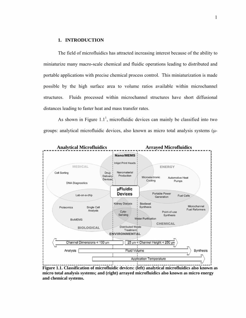
As shown in Figure 1.11, microfluidic devices can mainly be classified into two
groups: analytical microfluidic devices, also known as micro total analysis systems (μ-
Analytical Microfluidics Arrayed Microfluidics
Figure 1.1. Classification of microfluidic devices: (left) analytical microfluidics also known as micro total analysis systems; and (right) arrayed microfluidics also known as micro energy and chemical systems.
2
TAS), and arrayed microfluidic devices, referred to as micro energy and chemical
systems (MECS). These two major categories have significant differences in their
function and in the materials and fabrication technologies used to implement them. The
purpose of analytical devices is to quickly assay small samples of fluids to determine
composition and other information about the sample. Continued advances in analytical
microfluidics are fueling radical innovations in medicine. These applications tend to
operate near room temperature such that device materials include many polymers.
Further, analytical devices require higher levels of control and sensing which is
compatible with many polymer, glass and silicon architectures. These materials are all
congruent with existing microelectronics and MEMS fabrication technologies.
Arrayed microchannel devices are typically produced through a lamination
process where thin metal shims are cut, patterned, and possibly coated. The prepared
shims are then stacked in an appropriate sequence and bonded by diffusion bonding or
diffusion brazing. Regardless of the bonding technique used, the assembly is usually held
under pressure in an inert or reducing atmosphere and heated by radiation and/or free
convection in a furnace or hot press. A recent study by OSU has shown that bonding
cycle time is one of the largest cost factors in the short-run production of arrayed
microchannel components, representing between 40 and 87% of the fabrication cost.
Other studies have shown that thermal gradients caused by fast heating and cooling rates
at the beginning and end of the diffusion bonding cycle is a major source of microchannel
warpage. This research is primarily aimed at significantly reducing the bonding cycle
time and associated warpage associated with rapid and uniform heating and cooling of
arrayed microchannel components during the bonding process.

3
In the following manuscript, two papers are used to describe a unique internal
convective heating (ICH) technique for utilizing the internal flow passages of arrayed
microchannel (ArM) devices to deliver thermal energy convectively to the internal
surfaces of ArM devices during diffusion bonding. The first paper investigates the
feasibility of the ICH method by studying leakage rates and heat exchanger requirements
within the process. The second paper documents the primary results and conclusions
obtained in this research. Findings show that the novel ICH technique is feasible with
advantages over existing vacuum hot press methods of diffusion bonding. The research
goes on to define some of the practical constraints associated with this method.
Appendices are provided at the end of this manuscript to support these findings by
providing additional results. The next chapter investigates the feasibility of the ICH
method by studying leakage rates and thermal requirements within the process
4
2. LEAKAGE RATES AND THERMAL REQUIREMENTS FOR THE DIFFUSION BONDING OF MICROCHANNEL ARRAYS VIA INTERNAL CONVECTIVE HEATING 2nd International Conference on Micromanufacturing 2007
Sumantra Bose1, Daniel R. Palo2 ,Brian K. Paul3
1Sumantra Bose; Dept. of Industrial Eng., Oregon State University; e-mail: [email protected] 2Daniel R. Palo; Pacific Northwest National Laboratory; e-mail:[email protected] 3Brian K. Paul ; Dept. of Industrial Eng. Oregon State University; e-mail: [email protected] Abstract
Diffusion bonding cycle times can be a large cost factor in the production of metal
microchannel devices. The challenge is to significantly minimize this cost by reducing
the bonding cycle time through rapid and uniform heating and cooling within the bonding
process. Heating rates in diffusion bonding processes are typically limited by the need to
minimize internal thermal gradients during bonding. A novel method is described which
takes advantage of the internal flow passages within microchannel devices for convective
heat transfer during the bonding process. The internal convective heating (ICH) technique
makes use of heated inert gas to provide the microchannel assembly with rapid and
uniform heat input. This paper investigates the feasibility of the ICH method by studying
leakage rates and thermal requirements within the process.
5
Introduction
Microlamination is a process architecture commonly used to fabricate monolithic,
multi-layered bulk microfluidic devices having complex internal cavities consisting of
highly parallel arrays of microchannelsD
2DF
,FD
3D. Microchannels are good for increasing surface
to volume ratios critical for reducing diffusional distances in heat and mass transfer.
Arrays are necessary to increase flow rates and throughput.
Microlamination involves the patterning and bonding of thin layers of material, called
laminae. Laminae can be designed to implement a host of functions (e.g., mixing,
reaction, heat transfer) within a microchannel format. For instance, deposition of catalytic
materials on laminae can be used in the fabrication of microreactors to conduct
heterogeneous catalystsD
4D. Patterning of the shims can be accomplished in large quantities
at low cost per shim by using photochemical machining or stamping processes. After
patterning of the individual fluidic layers, diffusion bonding is often used to consolidate a
stack of laminae. As implied above, stacking of laminae permits scale-up of
microchannel functionality. A critical step during the bonding of the patterned layers is
the proper alignment and registration of the layers relative to each other. Commonly,
alignment of the layers is achieved with pins and precise pinholes in the layersX. During
diffusion bonding, laminae are heated up to the bonding temperature under an applied
bonding pressure typically within a vacuum hot press (VHP). These pressure and
temperature conditions are held constant for a period of time necessary to convert the
layers into a monolithic device via solid state diffusion. Insufficient bonding conditions
can lead to poor bonding and leakageD
5D while extreme bonding conditions may lead to
deformed or collapsed channel features.
6
Researchers have developed and fabricated numerous microchannel-based reactors,
heat exchangers, and separators within the context of basic and applied research projects,
where unit cost is unimportant relative to other factors such as performance, weight, and
size. As microtechnology has progressed, the need and desire for lower-cost
manufacturing techniques have come to the forefront in making microtechnology
acceptable to clients and potential customers. A recent study by OSU has shown that
bonding cycle time can be one of the largest cost factors in the production of bonded
devices, representing between 40% and 87% of the fabrication cost. The report also
found that capital cost and heating and cooling rates were very strong drivers of cost
performance.
Internal Convective Heating
Heating and cooling rates in furnace bonding processes are usually limited by the need
to minimize thermal gradients within the assembly (shim stack) being bonded. Rapid
heating of the assembly by external heating and intra-assembly conduction leads to
significant thermal gradients within the assembly, which can cause shim deformation,
channel obstruction, and residual mechanical stresses within the finished part. These
mechanical considerations limit the heating/cooling rate to about 5 ºC per minute
depending upon the size of the hot press and the size of the device being bonded. For
bonding cycles that require temperatures around 1000 ºC, this represents a very long
duration during ramp-up. This problem is further compounded as the size of the bonded
device increases. Since microchannel devices are already equipped with internal flow
channels, we have proposed to utilize these channels for heat transfer in the rapid and

7
uniform heating and
cooling of the laminated
assembly during diffusion
bonding. It is expected
that heated fluid (inert gas,
reducing gas, or other) can
be forced through the
prepared shim stack to
provide heat for bonding.
This internal convective heating (ICH) bonding technique can provide the assembly with
rapid heat input while minimizing thermal gradients within the assembly.
As compared to traditional VHP methods, it is conceivable that the ICH method could
bring the system up to the bonding temperature in less than 10 minutes depending upon
device and process constraints such as thermal gradients allowable within the stack.
Heating and cooling times on this order could lead to cycle time reduction of more than
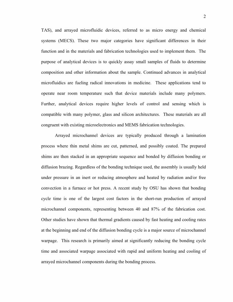
50% as shown in Figure 2.1. In Figure 2.1, the constant temperature region is where the
bonding pressure is applied and diffusion bonding takes place.
One of the challenges of the ICH approach is the potential for gas leakage during
bonding. Too high of a leakage rate could factor into the economics of the process.
Another challenge is the design of a thermal system capable of delivering the necessary
heat at the proper flow rates for controlling the process. The objective of this paper is to
analyze leakage rates and thermal requirements for the ICH process.
0100200300400500600700800900
10001100
0 50 100 150 200 250 300 350 400 450 500 550
Time(mins)
Tem
p(C
)
VHPICH
Figure 2.1. Comparison of cycle time on VHP and ICH.

8
Process Design
A process design was developed for a typical 25 x 25 mm microchannel test article
made from stainless steel 316L. The basic design of the shim assembly consists of two
stainless steel 316L flow shims (1.0”x1.0”x.015”) sandwiched between two end plates
and a middle plate. The end plates provide manifolding to the flow shims and the middle
plate keeps the two flow shim fluid streams separate.
Figure 2.2 shows a simplified schematic of the ICH test stand designed to support
representative bonding experiments. As shown in the system schematic, a heat exchanger
is used at the inlet to provide heat to the inert gas being used as the heat transfer fluid.
Argon is used as the heat transfer fluid because of its inert nature and low cost. A platen
assembly was required to couple the gas stream into the pressure subsystem (Figure 2.3).
Top platen
Bottom platen
Alignment pin
Shimstack
Insulation
Insulation
End plate
End plate
Inert gas feed
stream(Ar)
Flow Meter
(Outlet)
Inlet
Inlet
Outlet
Outlet
Heat exchanger
(Inlet)Flow meter (Inlet)
Heat exchanger
(Outlet)
Figure 2.2. Simplified schematic of an internal convective heating setup.

9
For proof-of-principle testing, it was
decided that bonding pressure could be
supplied by the hydraulic subsystem of a
VHP. This requires the ICH test stand to
be set up adjacent to a VHP and operate
within the work envelope of the system. In
the current test stand, the work envelope is
constrained to a maximum of a 75 mm
diameter. During warm-up, the purpose of the clamping mechanism is to provide enough
pressure to keep the heat exchange gas from leaking out between the shims. During the
bonding period, the pressure is required for solid state diffusion across faying surfaces.
Typical pressures of 1000-1200 psi are required during the bonding step.
Both the heat exchanger assembly and the shim stack require thermal isolation for
proper operation, efficiency, and safety. Zircal-95 was chosen as the insulation material
for the platen assembly. An enclosure around the shim stack is also envisioned to provide
a safety shield. Flow controllers, thermocouples, and flow meters are designed to provide
feedback for the process. A computer-based data acquisition system will be used to
control the process.
Leakage Study
The objective of the leakage study was to investigate the amount of gas leakage
resulting from an ICH setup. The leakage from between the laminae and platens was
studied as a function of applied pressure to the stack and surface conditions of the
Figure 2.3. Assembly of platens and laminae.
10
laminae.
Leakage tests were performed to determine the clamping pressure required to acceptably
minimize leakage of convective gases from the bonding assembly. It was hoped that
clamping pressures would be on the same order of magnitude as bonding pressure or
lower. The temperature of the gas in the assembly will be near or at 10000C, which is the
required temperature for the diffusion bonding of stainless steel. Thus the minimization
of leakage is also critical to maximize safety. Process conditions to be investigated by the
study are shown in Table 1.
Experimental Setup
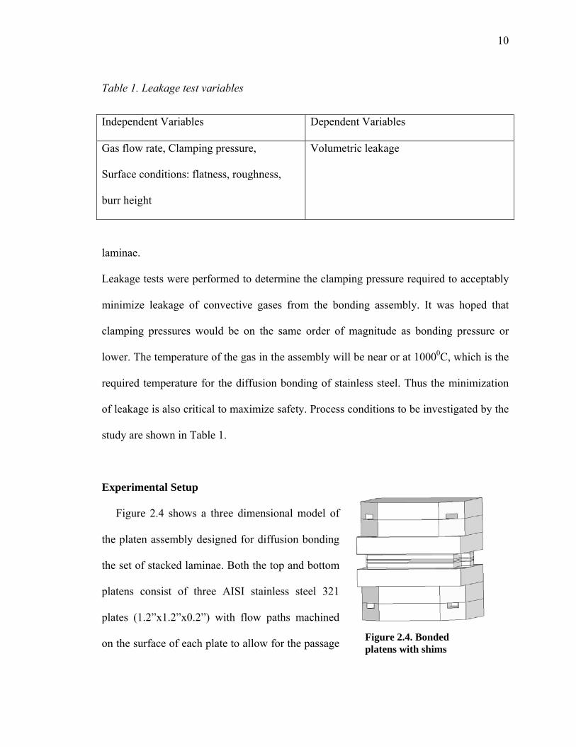
Figure 2.4 shows a three dimensional model of
the platen assembly designed for diffusion bonding
the set of stacked laminae. Both the top and bottom
platens consist of three AISI stainless steel 321
plates (1.2”x1.2”x0.2”) with flow paths machined
on the surface of each plate to allow for the passage
Table 1. Leakage test variables
Independent Variables Dependent Variables
Gas flow rate, Clamping pressure,
Surface conditions: flatness, roughness,
burr height
Volumetric leakage
Figure 2.4. Bonded platens with shims
11
of argon gas. Each set of platens was diffusion bonded in a VHP at a pressure of 1000 psi
and a temperature of 1000°C for 3 hours. The platens consist of an inlet and an outlet slot
allowing for the entry and exit of argon gas. Stainless steel tubing was TIG welded onto
the inlet and outlet slots of each platen. Holes are provided on the platens for pin
alignment of the laminated shims.
Before stacking, the shims were cleaned in a solution of Citranox and water. Grease is
removed by acetone followed by ethanol and de-ionized water for removal of residues.
The set of cleaned laminae were then assembled and aligned with the slots provided on
the bonded platen assembly using 1/16” diameter alignment pins. Figure 2.4 shows the
shim assembly stacked in between the two platens, ready to be leak tested.
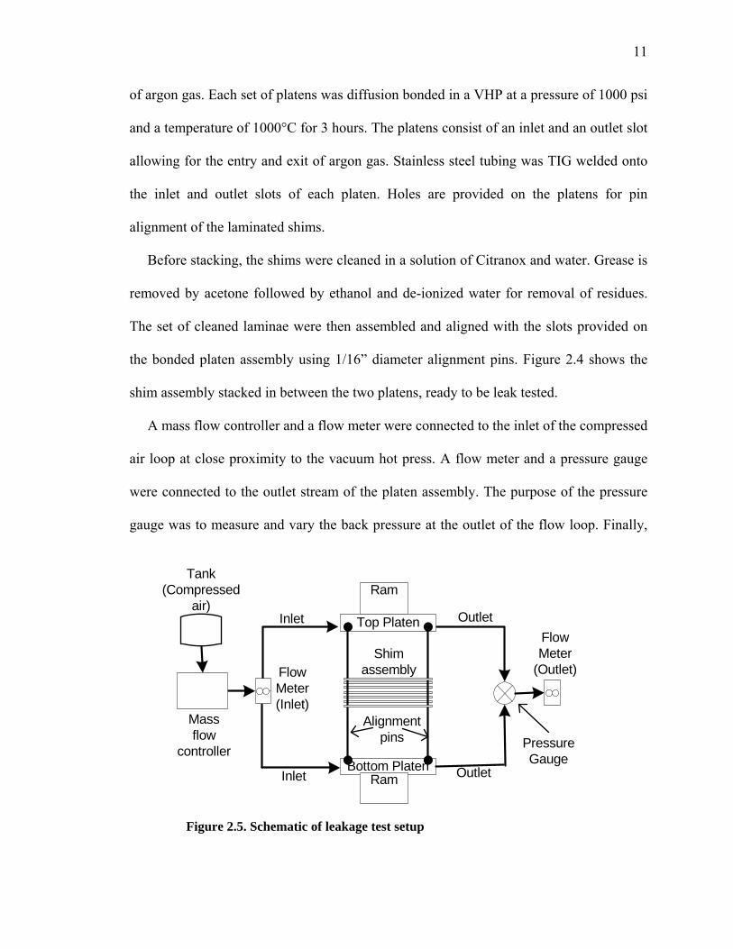
A mass flow controller and a flow meter were connected to the inlet of the compressed
air loop at close proximity to the vacuum hot press. A flow meter and a pressure gauge
were connected to the outlet stream of the platen assembly. The purpose of the pressure
gauge was to measure and vary the back pressure at the outlet of the flow loop. Finally,
Top Platen
Bottom Platen
Inlet
Alignment pins
Outlet
Inlet Outlet
Ram
Ram
Flow Meter(Inlet)
Flow Meter
(Outlet)
Pressure Gauge
Tank (Compressed
air)
Shim assembly
Mass flow
controller
Figure 2.5. Schematic of leakage test setup
12
the assembly was clamped between the hydraulic rams of the vacuum hot press. The
schematic representation of the setup used in performing the leak tests is shown in Figure
2.5.
As a preliminary leak test, the platens were clamped together with a ‘C-clamp’. The
assembly was immersed in a beaker containing water, and pressure was applied to check
for bubbles. There was no bubble formation within the platens up to a pressure of 35 psi,
indicating no leakage from the part.
Experimental Results
The platen assembly was clamped in between the rams of the vacuum hot press and a
pressure was kept at a minimum level. The compressed air was turned on and passed
through the platen assembly. The clamping pressure was gradually increased using the
pressure control panel on the vacuum hot press. Volumetric flow rates at the outlet were
measured with increasing clamping pressure using the flowmeter provided at the outlet
shown in Figure 2.5. Leakage measurements were carried out by varying back pressures
on the outlet ranging from 0 to 20 psi. The flow rate at the inlet was maintained at a
constant rate of 21.75 SLPM.
13
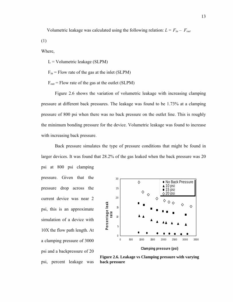
Volumetric leakage was calculated using the following relation: L = Fin – Fout
(1)
Where,
L = Volumetric leakage (SLPM)
Fin = Flow rate of the gas at the inlet (SLPM)
Fout = Flow rate of the gas at the outlet (SLPM)
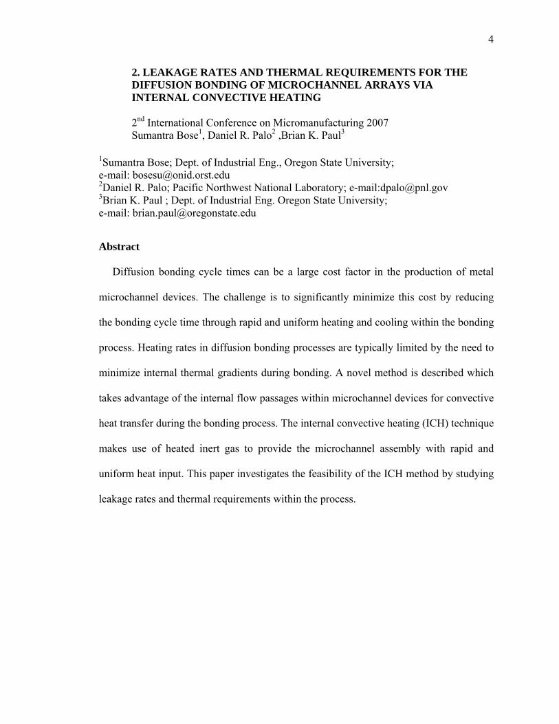
Figure 2.6 shows the variation of volumetric leakage with increasing clamping
pressure at different back pressures. The leakage was found to be 1.73% at a clamping
pressure of 800 psi when there was no back pressure on the outlet line. This is roughly
the minimum bonding pressure for the device. Volumetric leakage was found to increase
with increasing back pressure.
Back pressure simulates the type of pressure conditions that might be found in
larger devices. It was found that 28.2% of the gas leaked when the back pressure was 20
psi at 800 psi clamping
pressure. Given that the
pressure drop across the
current device was near 2
psi, this is an approximate
simulation of a device with
10X the flow path length. At
a clamping pressure of 3000
psi and a backpressure of 20
psi, percent leakage was
0
5
10
15
20
25
30
0 500 1000 1500 2000 2500 3000 3500
Clamping pressure (psi)
Perc
enta
ge le
ak ra
te
No Back Pressure10 psi15 psi20 psi
Figure 2.6. Leakage vs Clamping pressure with varying back pressure
14
found to be approximately 15%. This would be near the upper end of the bonding
pressure.
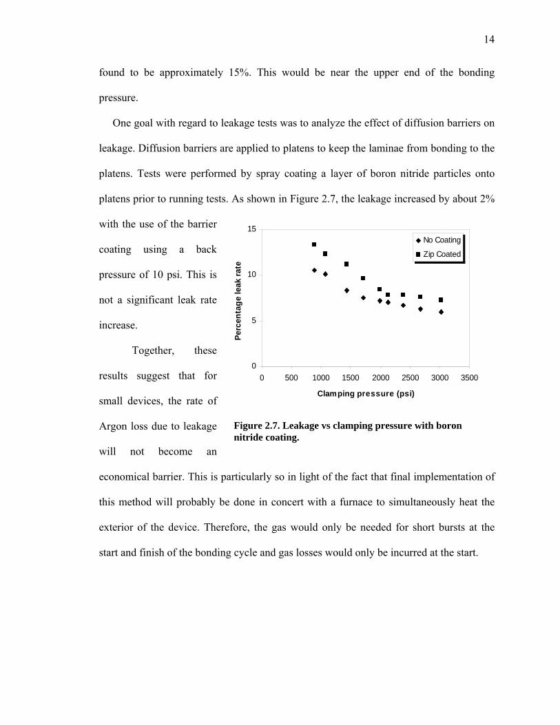
One goal with regard to leakage tests was to analyze the effect of diffusion barriers on
leakage. Diffusion barriers are applied to platens to keep the laminae from bonding to the
platens. Tests were performed by spray coating a layer of boron nitride particles onto
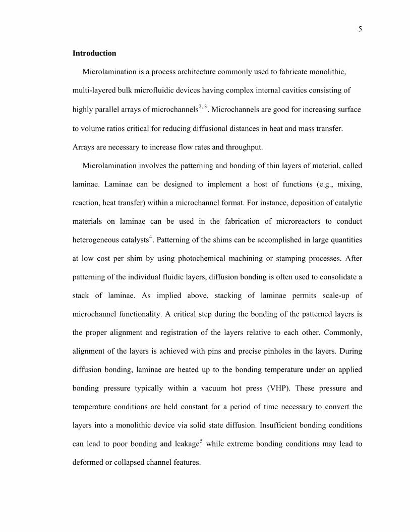
platens prior to running tests. As shown in Figure 2.7, the leakage increased by about 2%
with the use of the barrier
coating using a back
pressure of 10 psi. This is
not a significant leak rate
increase.
Together, these
results suggest that for
small devices, the rate of
Argon loss due to leakage
will not become an
economical barrier. This is particularly so in light of the fact that final implementation of
this method will probably be done in concert with a furnace to simultaneously heat the
exterior of the device. Therefore, the gas would only be needed for short bursts at the
start and finish of the bonding cycle and gas losses would only be incurred at the start.
Figure 2.7. Leakage vs clamping pressure with boron nitride coating.
0
5
10
15
0 500 1000 1500 2000 2500 3000 3500
Clamping pressure (psi)
Perc
enta
ge le
ak ra
teNo Coating
Zip Coated
15
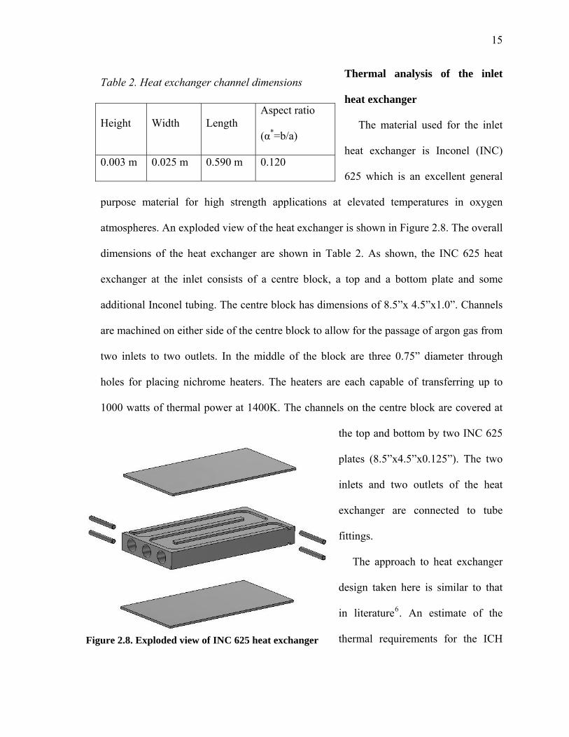
Thermal analysis of the inlet
heat exchanger
The material used for the inlet
heat exchanger is Inconel (INC)
625 which is an excellent general
purpose material for high strength applications at elevated temperatures in oxygen
atmospheres. An exploded view of the heat exchanger is shown in Figure 2.8. The overall
dimensions of the heat exchanger are shown in Table 2. As shown, the INC 625 heat
exchanger at the inlet consists of a centre block, a top and a bottom plate and some
additional Inconel tubing. The centre block has dimensions of 8.5”x 4.5”x1.0”. Channels
are machined on either side of the centre block to allow for the passage of argon gas from
two inlets to two outlets. In the middle of the block are three 0.75” diameter through
holes for placing nichrome heaters. The heaters are each capable of transferring up to
1000 watts of thermal power at 1400K. The channels on the centre block are covered at
the top and bottom by two INC 625
plates (8.5”x4.5”x0.125”). The two
inlets and two outlets of the heat
exchanger are connected to tube
fittings.
The approach to heat exchanger
design taken here is similar to that
in literatureD
6D. An estimate of the
thermal requirements for the ICH
Table 2. Heat exchanger channel dimensions
Height Width Length Aspect ratio
(α*=b/a)
0.003 m 0.025 m 0.590 m 0.120
Figure 2.8. Exploded view of INC 625 heat exchanger
16
system can be made by considering the enthalpy of the thermal mass in the system and
making assumptions about heat losses. In our model, we are assuming that heat transfer
to the gas occurs from only one wall. This wall is held at a constant temperature of
1200K. The constant temperature boundary condition is present when the duct has a
constant wall temperature in both the circumferential and the axial directions.
In fluid mechanics, the Reynolds number is the ratio of inertial forces to viscous
forces and consequently it quantifies the relative importance of these two types of forces
for given flow conditionsD
7D. Thus, it is used to identify different flow regimes, such as
laminar or turbulent flow.
Re = (u. Dh)/ ν (2)
Where,
u ~ average velocity of the gas
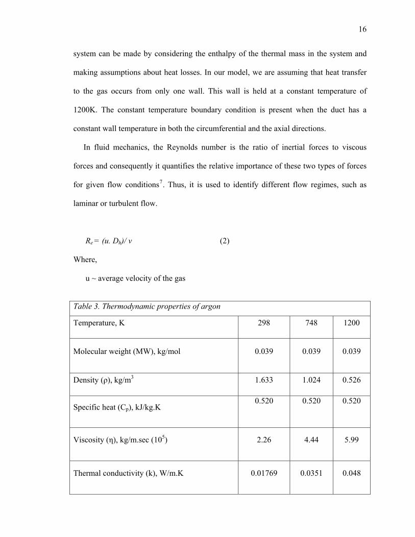
Table 3. Thermodynamic properties of argon
Temperature, K 298 748 1200
Molecular weight (MW), kg/mol 0.039 0.039 0.039
Density (ρ), kg/m3 1.633 1.024 0.526
Specific heat (Cp), kJ/kg.K 0.520
0.520
0.520
Viscosity (η), kg/m.sec (105) 2.26 4.44 5.99
Thermal conductivity (k), W/m.K 0.01769 0.0351 0.048

17
ν ~ kinematic fluid viscosity, ν = η / ρ
η , ρ are viscosity and density of argon gas respectively
and,
u = Q / A (3)
where,
Q is the volumetric flow rate
A is the cross sectional area of channel
u = 0.000416 m3/sec / 0.0000772 m2
= 5.388 m/sec
In this application, the value of the Reynolds number above 300 K lies below 2300
suggesting laminar flow. The thermodynamic properties of argon gas were calculated at
different temperatures ranging from 298-1200K D
8D. The values of molecular weight,
density, specific heat, viscosity and thermal conductivity of argon at 298, 748, and 1200K
are provided in Table 3.
In order to design a plate-type heat exchanger capable of meeting these
requirements, the mass flow rate and an estimation of the convective heat transfer
coefficient is needed.
Coefficient of heat transfer and mass flow rate
The convective heat transfer coefficient for this application can be estimated by D
9DF
,FD
10D:
h = NuT. k/ Dh (2)
Where,
NuT ~ Nusselt number at constant wall temperature of 925 oC

18
Dh ~ hydraulic
diameter
k ~ thermal
conductivity of
argon
h ~ coefficient
of heat transfer
The Nusselt number for fully developed laminar flow in rectangular ducts with heat
transfer through one wall is 0.5322 [7]. The hydraulic diameter is given by
Dh = 4ab/(2*(a+b)) (4)
where
a and b are channel height and width respectively
Dh = 0.00543m
The mass flow rate can be calculated as
m = ρ .Q (5)
where,
ρ ~ density of argon gas
Q ~ volumetric flow rate
The required volumetric flow rate for incoming argon gas at 1200K has been
calculated to be 25 SLPM according to enthalpy requirements and heat losses. Using (4)
and (5), the coefficient of heat transfer and mass flow rate was calculated and the values
obtained are shown in Table 4.
Table 4. Coefficient of heat transfer and mass flow rates
Temperature (Kelvin) 298 748 1200
Heat Transfer Coefficient(W /m2K) 1.832 3.370 4.702
Mass flow rate(kg/sec) 0.00067 0.00042 0.00021
19
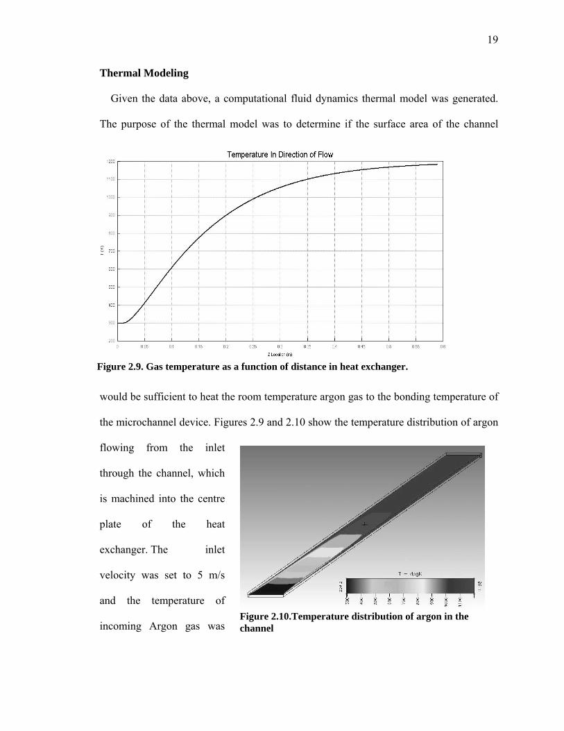
Thermal Modeling
Given the data above, a computational fluid dynamics thermal model was generated.
The purpose of the thermal model was to determine if the surface area of the channel
would be sufficient to heat the room temperature argon gas to the bonding temperature of
the microchannel device. Figures 2.9 and 2.10 show the temperature distribution of argon
flowing from the inlet
through the channel, which
is machined into the centre
plate of the heat
exchanger. The inlet
velocity was set to 5 m/s
and the temperature of
incoming Argon gas was
Figure 2.9. Gas temperature as a function of distance in heat exchanger.
Figure 2.10.Temperature distribution of argon in the channel

20
set to 300K. Argon gas properties were provided in piece-wise linear form using data for
temperatures 298K, 748K, and 1200K. All walls were set to a no slip condition at 1198K.
In Figure 2.9, the axial thermal distribution shows a gradual change in temperature
from the inlet towards the outlet. This analysis suggests that the Argon gas was heated to
greater 1150 K within a distance approximately equal to 0.5 m from inlet. This analysis
was used to validate the dimensions of the heat exchanger. Longer term, a recuperation
system to recycle inert gas from the outlet back into the heat exchange device is
envisioned.
Summary and future work
Leakage tests have been performed to determine the clamping pressure required to
acceptably minimize the leakage of convective gases from the bonding assembly. The
low leak rates confirm the feasibility of operating the ICH system for bonding
microchannel devices. A plate type heat exchanger has been designed which successfully
heats argon to the bonding temperatures required. This heat exchanger will provide the
microchannel assembly with rapid heat input.
The heat exchanger is currently being fabricated using conventional machinery in the
OSU fabrication facility. Once this heat exchanger has been fabricated, the final test loop
will be assembled and operated. Eventually, samples diffusion bonded on the VHP will
be compared to those successfully bonded using internal convective heating to evaluate
the bond quality of the ICH bonding system for bonding microchannel devices.

21
3 AN INTERNAL CONVECTIVE HEATING TECHNIQUE FOR
DIFFUSION BONDING HIGHLY PARALLEL MICROCHANNEL
ARCHITECTURES
S. Bose, B. K. Paul, D. R. Palo
1 0BINTRODUCTION
The field of microfluidics has attracted increasing interest because of the ability to
miniaturize many macro-scale chemical and fluidic operations leading to distributed and
portable applications with precise chemical process control. This miniaturization is made
possible by the high surface area to volume ratios available within microchannel
structures. Fluids processed within microchannel structures have short diffusional
distances leading to faster heat and mass transfer rates.
Microfluidic devices mainly can be classified into two groups: analytical
microfluidic devices, also known as micro total analysis systems (μ-TAS), and arrayed
microfluidic devices, referred to as micro energy and chemical systems (MECS).
Continued advances in analytical microfluidics are fueling radical innovations in
medicine. Analytical microfluidics assay small samples of fluids near room temperature
to determine composition and other information about the sample. These requirements
are all congruent with existing MEMS and BioMEMS fabrication technologies.
In contrast, arrayed microfluidic devices are designed to process bulk quantities of
fluids through the use of microchannel array D
11D. Potential arrayed microfluidic
applications exist in abundance. Residential air conditioning could be made “ductless”
through the application of many distributed micro heat pumps. Biodiesel microreactors
have the potential to shrink plant size by 100 to 1000 times greatly reducing capital
22
investments. At-home, portable kidney dialysis will make life more manageable and cost
effective for a whole new generation of kidney patients. Many arrayed microfluidic
applications require materials capable of withstanding higher temperatures and higher
thermal transport. Because they process bulk amounts of fluid, these devices tend to be
much larger than analytical devices requiring the use of low-cost, engineering materials.
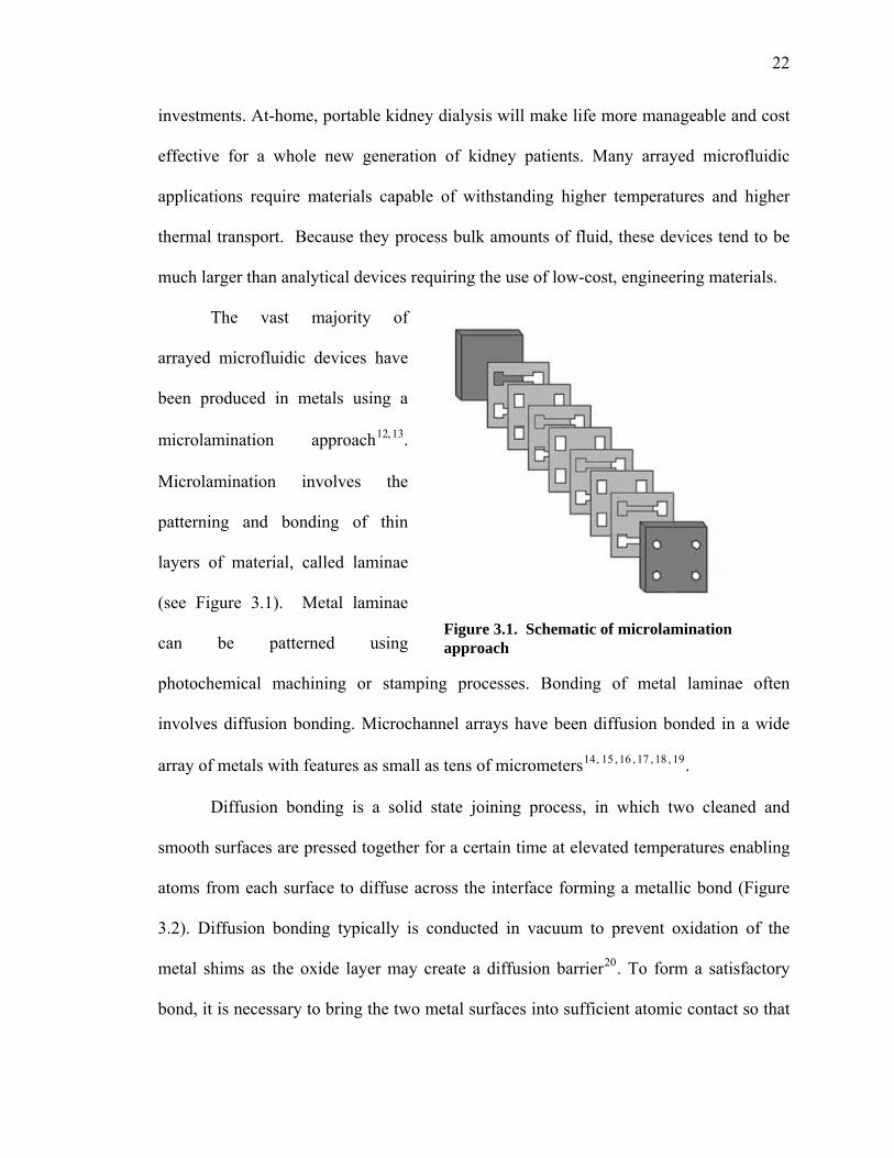
The vast majority of
arrayed microfluidic devices have
been produced in metals using a
microlamination approachD
12,D
13.
Microlamination involves the
patterning and bonding of thin
layers of material, called laminae
(see Figure 3.1). Metal laminae
can be patterned using
photochemical machining or stamping processes. Bonding of metal laminae often
involves diffusion bonding. Microchannel arrays have been diffusion bonded in a wide
array of metals with features as small as tens of micrometersD
14DF
,FD
15DF
,FD
16DF
,FD
17DF
,FD
18DF
,FD
19D.
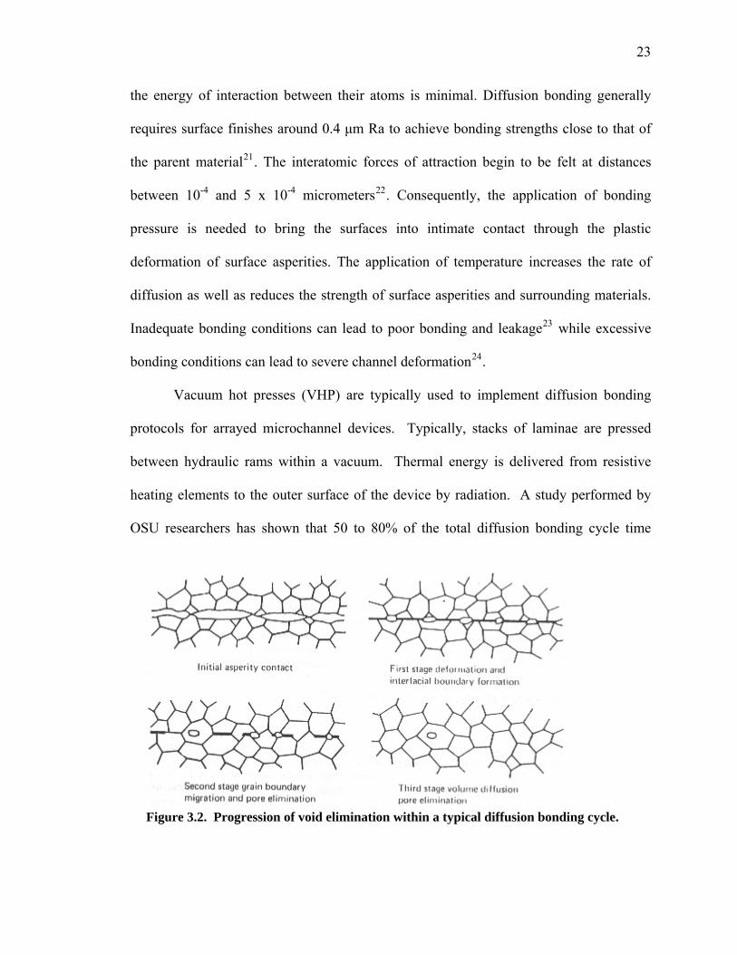
Diffusion bonding is a solid state joining process, in which two cleaned and
smooth surfaces are pressed together for a certain time at elevated temperatures enabling
atoms from each surface to diffuse across the interface forming a metallic bond (Figure
3.2). Diffusion bonding typically is conducted in vacuum to prevent oxidation of the
metal shims as the oxide layer may create a diffusion barrierD
20D. To form a satisfactory
bond, it is necessary to bring the two metal surfaces into sufficient atomic contact so that
Figure 3.1. Schematic of microlamination approach
23
the energy of interaction between their atoms is minimal. Diffusion bonding generally
requires surface finishes around 0.4 μm Ra to achieve bonding strengths close to that of
the parent materialD
21D. The interatomic forces of attraction begin to be felt at distances
between 10-4 and 5 x 10⁻⁴ micrometersD
22D. Consequently, the application of bonding
pressure is needed to bring the surfaces into intimate contact through the plastic
deformation of surface asperities. The application of temperature increases the rate of
diffusion as well as reduces the strength of surface asperities and surrounding materials.
Inadequate bonding conditions can lead to poor bonding and leakageD
23D while excessive
bonding conditions can lead to severe channel deformationD
24D.
Vacuum hot presses (VHP) are typically used to implement diffusion bonding
protocols for arrayed microchannel devices. Typically, stacks of laminae are pressed
between hydraulic rams within a vacuum. Thermal energy is delivered from resistive
heating elements to the outer surface of the device by radiation. A study performed by
OSU researchers has shown that 50 to 80% of the total diffusion bonding cycle time
Figure 3.2. Progression of void elimination within a typical diffusion bonding cycle.
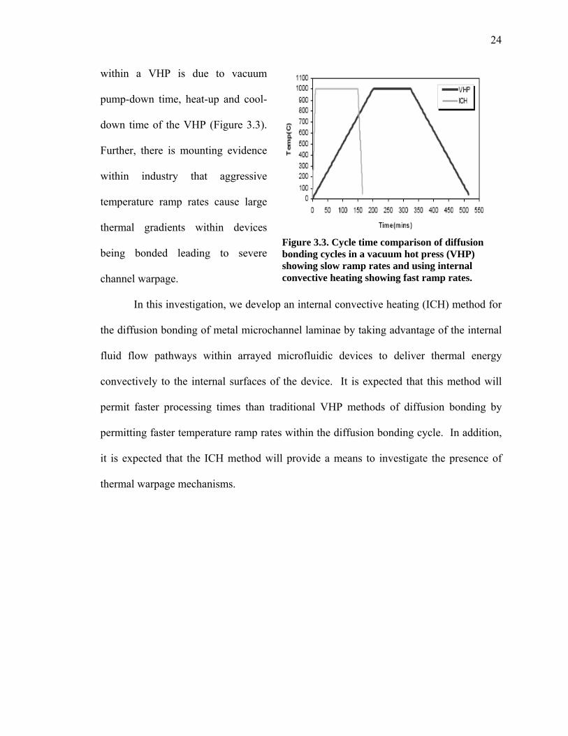
24
within a VHP is due to vacuum
pump-down time, heat-up and cool-
down time of the VHP (Figure 3.3).
Further, there is mounting evidence
within industry that aggressive
temperature ramp rates cause large
thermal gradients within devices
being bonded leading to severe
channel warpage.
In this investigation, we develop an internal convective heating (ICH) method for
the diffusion bonding of metal microchannel laminae by taking advantage of the internal
fluid flow pathways within arrayed microfluidic devices to deliver thermal energy
convectively to the internal surfaces of the device. It is expected that this method will
permit faster processing times than traditional VHP methods of diffusion bonding by
permitting faster temperature ramp rates within the diffusion bonding cycle. In addition,
it is expected that the ICH method will provide a means to investigate the presence of
thermal warpage mechanisms.
Figure 3.3. Cycle time comparison of diffusion bonding cycles in a vacuum hot press (VHP) showing slow ramp rates and using internal convective heating showing fast ramp rates.

25
2 1BEXPERIMENTAL APPROACH
Figure 3.4 is a conceptual diagram of the experimental test stand constructed to
support the internal convective heating (ICH) of arrayed microfluidic devices during
diffusion bonding. Considerations in the design of this setup included thermal and
bonding pressure delivery in addition to thermal isolation. High purity (99.99%) argon
gas was used as the medium for thermal delivery. An Inconel 625 heat exchanger was
designed and fabricated to transfer heat to the argon gas stream for delivery to the stack
of laminae to be diffusion bonded. Design of the heat exchanger has been explained
elsewhereD
25D. Hot gas flows from the heat exchanger into the platen assembly with the test
article and out to a large air handling system. Thermocouples were placed, as shown in
numbers one through seven in Figure 3.4 below, to provide temperature feedback for the
process. Specific locations included in one of the outlets of the heat exchanger (seven),
in the inlets (one and four) and outlets (three and six) of the platen assembly and adjacent
Figure 3.4. Conceptual ICH diagram with thermocouple placements and PID loop
26
to the surface of the top (two) and bottom (four) platens. Temperature of the inlet gas was
monitored using thermocouples one and four connected to data acquisition software. Gas
flow was set manually using a mass flow controller with mass flow meters for
monitoring. Before the entire process was run, the system was checked for leakage. This
was done by checking the gas pressures at the inlet and outlet, and was found to be the
same. This ensured that the mass flow rates at the upper and lower loops are equal. A
pressure was included in the system to have an estimate of the back pressures in the flow
loop.
The function of the bonding pressure delivery system was to provide enough
pressure during heat-up to keep the heat transfer gas from leaking out between the shims
and to provide enough pressure during the dwell period to result in a strong bond between
the shims. Bonding pressure was supplied by a hydraulic ram through upper and lower
platens. Platens were adapted to allow for gas flow into and out of the lamina stack.
Platens were made from 321 stainless steel to withstand the temperatures and pressures
required for the bonding process.
The high temperature portions of the thermal delivery system required thermal
insulation and enclosure for proper operation, efficiency, and safety. To thermally isolate
the ICH system from the hydraulic press, thick ceramic insulation plates (Zircal-95) were
placed between the platens and the hydraulic ram. Fiber insulation (K-wool) was used to
further isolate high temperature sections from the ambient. A physical barrier was placed
around the shim stack for safety. A computer-based data acquisition system (Omega
OMB-DAQ-54) was used to control the temperature of the inlet gas and to monitor the
temperature, flow and pressure of the gas within the system.
27
8B2.1 THERMAL LOAD AND DISTRIBUTION
Before proceeding with experiments, efforts were made to determine the thermal
load and conditions necessary to provide the thermal distribution required for diffusion
bonding via internal convective heating of the microchannel test article. To size the
thermal load required for the ICH method of diffusion bonding, a simple energy balance
was used:
A pA BT ss pss RTm c T dt m c T⎡ ⎤⋅ ⋅Δ = ⋅ ⋅Δ⎣ ⎦∫ (1)
where Am is the mass flow rate of argon, pAc is the specific heat of argon, BTTΔ is the
difference between the current temperature and the incoming temperature of the gas, t is
time, mss is the mass of the stainless steel platen assembly and post-heat exchanger
tubing, cpss is the specific heat of stainless steel and RTTΔ is the difference between the
current temperature and room temperature. This model assumes that all of the heat in the
argon flow is transferred directly to the metal mass in the platen assembly and tubing.
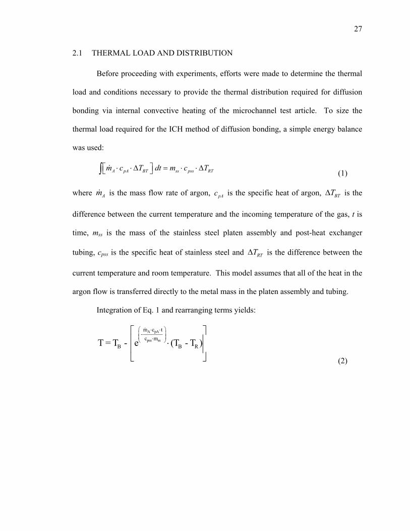
Integration of Eq. 1 and rearranging terms yields:
A pA
pss ss
m c t-
c mB B RT = T - e (T - T )
⎛ ⎞⋅ ⋅⎜ ⎟⎜ ⎟⋅⎝ ⎠
⎡ ⎤⎢ ⎥⋅⎢ ⎥⎣ ⎦ (2)
28
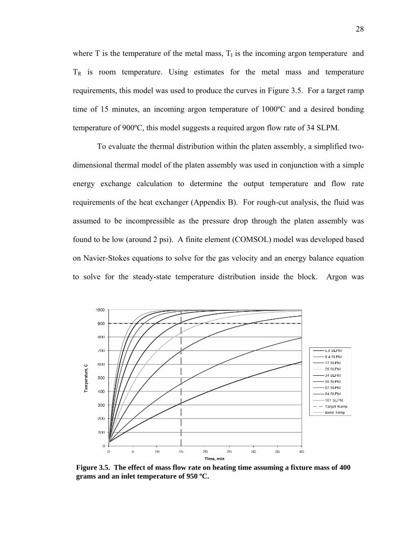
where T is the temperature of the metal mass, TI is the incoming argon temperature and
TR is room temperature. Using estimates for the metal mass and temperature
requirements, this model was used to produce the curves in Figure 3.5. For a target ramp
time of 15 minutes, an incoming argon temperature of 1000ºC and a desired bonding
temperature of 900ºC, this model suggests a required argon flow rate of 34 SLPM.
To evaluate the thermal distribution within the platen assembly, a simplified two-
dimensional thermal model of the platen assembly was used in conjunction with a simple
energy exchange calculation to determine the output temperature and flow rate
requirements of the heat exchanger (Appendix B). For rough-cut analysis, the fluid was
assumed to be incompressible as the pressure drop through the platen assembly was
found to be low (around 2 psi). A finite element (COMSOL) model was developed based
on Navier-Stokes equations to solve for the gas velocity and an energy balance equation
to solve for the steady-state temperature distribution inside the block. Argon was
Figure 3.5. The effect of mass flow rate on heating time assuming a fixture mass of 400 grams and an inlet temperature of 950 ºC.
29
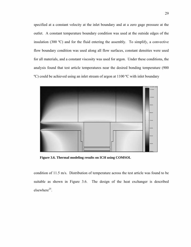
specified at a constant velocity at the inlet boundary and at a zero gage pressure at the
outlet. A constant temperature boundary condition was used at the outside edges of the
insulation (300 ºC) and for the fluid entering the assembly. To simplify, a convective
flow boundary condition was used along all flow surfaces, constant densities were used
for all materials, and a constant viscosity was used for argon. Under these conditions, the
analysis found that test article temperatures near the desired bonding temperature (900
ºC) could be achieved using an inlet stream of argon at 1100 ºC with inlet boundary
condition of 11.5 m/s. Distribution of temperature across the test article was found to be
suitable as shown in Figure 3.6. The design of the heat exchanger is described
elsewhere25X.
Figure 3.6. Thermal modeling results on ICH using COMSOL

30
2.2 PLATEN ASSEMBLY DESIGN
11B2.2.1 Microchannel Test Article
The test article design used in this study is shown in Figure 3.7. It was designed
to receive flow from both the top and bottom platens. The test article consisted of seven
316L stainless steel laminae with the following dimensions:
1. End plates (2) dimensions: 25 x 25 x 1.25 mm
2. Channel or flow laminae (4) dimensions: 25 x 25 x 0.375 mm
3. Middle lamina (1) dimensions: 25 x 25 x 0.375 mm
The two outer channel laminae were used to direct the transmission of bonding
pressure within the device. In this case, the application of bonding pressure over the
channels would lead to significant deflection of the end plates. Patterning of the
laminae was carried out with the use of wire EDM from annealed sheetstock.
Figure 3.7. Test article architecture
31
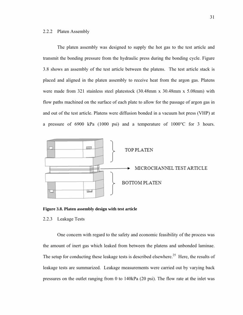
12B2.2.2 Platen Assembly
The platen assembly was designed to supply the hot gas to the test article and
transmit the bonding pressure from the hydraulic press during the bonding cycle. Figure
3.8 shows an assembly of the test article between the platens. The test article stack is
placed and aligned in the platen assembly to receive heat from the argon gas. Platens
were made from 321 stainless steel platestock (30.48mm x 30.48mm x 5.08mm) with
flow paths machined on the surface of each plate to allow for the passage of argon gas in
and out of the test article. Platens were diffusion bonded in a vacuum hot press (VHP) at
a pressure of 6900 kPa (1000 psi) and a temperature of 1000°C for 3 hours.
Figure 3.8. Platen assembly design with test article
13B2.2.3 Leakage Tests
One concern with regard to the safety and economic feasibility of the process was
the amount of inert gas which leaked from between the platens and unbonded laminae.
The setup for conducting these leakage tests is described elsewhere.X
25X Here, the results of
leakage tests are summarized. Leakage measurements were carried out by varying back
pressures on the outlet ranging from 0 to 140kPa (20 psi). The flow rate at the inlet was

32
maintained at a constant rate of 21.75 SLPM. Volumetric leakage was calculated using
the following relation:
L = Fin – Fout (1)
where
L ~ Volumetric leakage (SLPM)
Fin ~ Flow rate of the gas at the inlet (SLPM)
Fout ~ Flow rate of the gas at the outlet (SLPM)
Figure 3.9 shows the variation of volumetric leakage with increasing clamping
pressure at different back pressures. The leakage was found to be 1.73% at a clamping
pressure of 5520 kPa (800 psi) when there was no back pressure on the outlet line. This
result suggests that the clamping pressure needs to be on the same magnitude as the
bonding pressure. Prior studies have shown that the application of bonding pressure prior
to thermal cycling can generate significant microchannel warpageD
26D. This warpage has
Figure 3.9. Leak rate vs Clamping pressure with varying back pressures.

33
been found to be due to the differential thermal expansion between bonding fixtures and
laminae during ramp up. This finding suggests the need for the bonding platen to be
made from a material with matching thermal expansion characteristics. This further
confirmed the choice of platen material (321 stainless steel). Volumetric leakage was
found to increase with increasing back pressure. Back pressure simulates the type of
pressure conditions that might be found in larger devices. It was experimentally
determined that 28.2% of the gas leaked when the back pressure was 138kPa psi at a
clamping pressure of 5520 kPa. Given that the pressure drop across the current device
was nearly 14 kPa (2 psi), this is an approximate simulation of a device with 10X the
flow path length. At a clamping pressure of 20.7 MPa (3000 psi) and a backpressure of
138 kPa (20 psi), leakage was found to be approximately 15%. This would be near the
upper end of the bonding pressure.
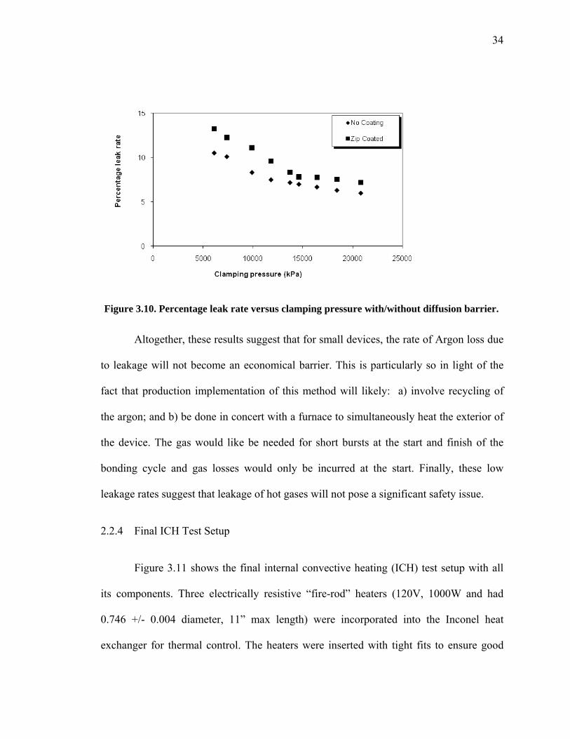
One goal with regard to leakage tests was to analyze the effect of diffusion
barriers on leakage. Diffusion barriers are applied to platens to keep the laminae from
bonding to the platens. Tests were performed by spray coating a layer of boron nitride
particles onto platens prior to running leak tests. As shown in Figure 3.10, the percentage
leak rate increased by about 2% with the use of the barrier coating using a back pressure
of 69kPa (10psi) which is not significant.
34
Altogether, these results suggest that for small devices, the rate of Argon loss due
to leakage will not become an economical barrier. This is particularly so in light of the
fact that production implementation of this method will likely: a) involve recycling of
the argon; and b) be done in concert with a furnace to simultaneously heat the exterior of
the device. The gas would like be needed for short bursts at the start and finish of the
bonding cycle and gas losses would only be incurred at the start. Finally, these low
leakage rates suggest that leakage of hot gases will not pose a significant safety issue.
14B2.2.4 Final ICH Test Setup
Figure 3.11 shows the final internal convective heating (ICH) test setup with all
its components. Three electrically resistive “fire-rod” heaters (120V, 1000W and had
0.746 +/- 0.004 diameter, 11” max length) were incorporated into the Inconel heat
exchanger for thermal control. The heaters were inserted with tight fits to ensure good
Figure 3.10. Percentage leak rate versus clamping pressure with/without diffusion barrier.

35
heat transfer to the surrounding metal. A Watlow single-loop, auto-tuning temperature
PID controller was used to control parameters for optimum system performance. The
argon gas flow was controlled using a mass flow controller. Inconel and stainless steel
tubing and Swagelok fittings were used to route both hot and cold gas streams. The
outlets of the heat exchanger were coupled with the inlets of the platen assembly using T-
type 1/4” inconel couplings.
KMQIN-032U-6 type thermocouples with diameter of 0.032” were inserted into
the platen assembly. Inlet and outlet thermocouples were snaked to the inlets and outlets
of the platen assembly to improve the accuracy of temperature measurement. A K type
thermocouple was placed at the outlet of the heat exchanger. The entire assembly was
mounted on a strut mount clamp made up of zinc plated stainless steel for withstanding
high temperatures. The ducting provided near the hot press received the hot gas, mixed it
with air and sent it out into the exhaust.
Figure 3.11. Internal convective heating test loop.
36
2.3 EXPERIMENTAL DESIGN
To evaluate the effectiveness of the ICH method, an experiment was conceived to
compare diffusion bonding results using ICH and VHP methods under identical
processing conditions. Final bonding conditions were: bonding pressure = 24.13 MPa;
bonding temperature = 900ºC; heating rate = 20 ºC/min; cooling rate = 20 ºC/min; and
time at bonding temperature = 2 hours. Gas flow rates for ICH cycles were maintained at
21.7 SLPM. Vacuum pressure within VHP cycles was held to 10-4 torr. Bonded test
articles were tested for device leakage, percent voids on the bond line and microchannel
warpage. These tests are described in more detail below.
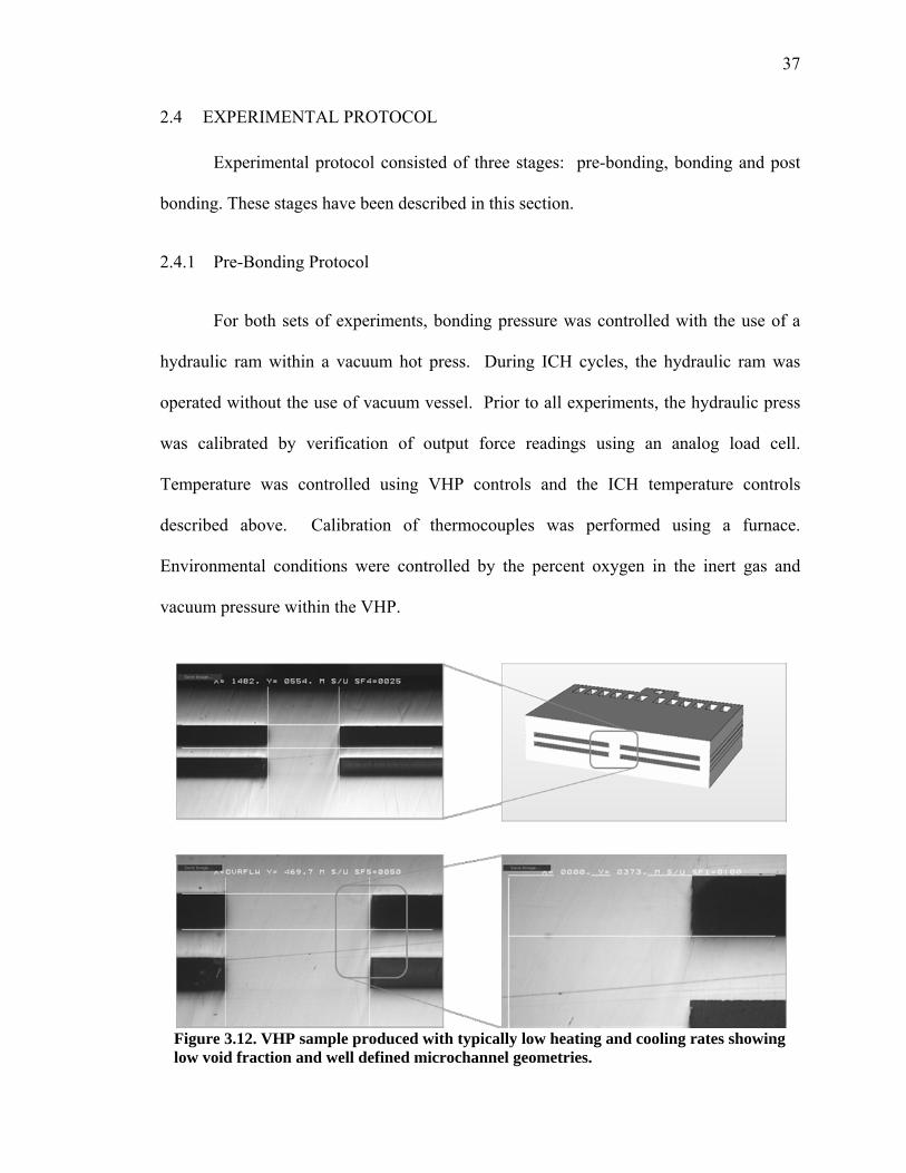
Final bonding conditions were chosen based on the results of preliminary testing
showing greatly differing amounts of microchannel warpage produced when using the
ICH and VHP methods under these conditions. To ensure that the microchannel warpage
detected was not due to creep or other failure mechanisms at the bonding temperatures
and pressures, an initial test article was produced at the same bonding temperatures and
pressures using greatly reduced heating and cooling rates (8 ºC/min). Figure 3.12 shows
metallographic cross-sections of a test article bonded under these conditions. The sample
shows very little warpage (1.8 ± .07 µm) with few voids on the bondline (0.27%). No
“barreling” of features is found suggesting that creep is not present.
37
9B2.4 EXPERIMENTAL PROTOCOL
Experimental protocol consisted of three stages: pre-bonding, bonding and post
bonding. These stages have been described in this section.
2.4.1 Pre-Bonding Protocol
For both sets of experiments, bonding pressure was controlled with the use of a
hydraulic ram within a vacuum hot press. During ICH cycles, the hydraulic ram was
operated without the use of vacuum vessel. Prior to all experiments, the hydraulic press
was calibrated by verification of output force readings using an analog load cell.
Temperature was controlled using VHP controls and the ICH temperature controls
described above. Calibration of thermocouples was performed using a furnace.
Environmental conditions were controlled by the percent oxygen in the inert gas and
vacuum pressure within the VHP.
Figure 3.12. VHP sample produced with typically low heating and cooling rates showing low void fraction and well defined microchannel geometries.
38
All samples were characterized and cleaned prior to bonding. The same lot of
annealed, cold-rolled stainless steel 316L was used for both VHP and ICH test articles.
Parallelism and surface conditions of all laminae were measured before each bonding
cycle using a Veeco profiler. The profiler was calibrated using surface roughness or step
height standards. Surface profiling included taking five scans at different places on the
test article surface for roughness, three scans at different edges for burr height and one 2
cm scan in the middle of the laminae. Average middleline roughness was found to be
0.32 ± 0.09 µm for ICH samples and 0.34 ± 0.06 µm for VHP samples. Average burr
height was found to be 8.2 ± 2.3 µm for ICH samples and 7.73 ± 3.4 µm for VHP
samples. Parallelism across a 2 cm scan was found to be 4.8 ± 0.7 µm for ICH samples
and 4.67 ± 0.4 µm for VHP samples. The cleaning process involved four steps: the
removal of oxides using a citranox agent; grease removal using acetone; removal of
residues using ethanol; and application of de-ionized water for final rinse.
15B2.4.2 In-process protocol
For ICH, the thermal cycle was controlled by the PID controller connected to the
thermocouples adjacent to the platens and the resistive heating elements. For VHP, two
thermocouples situated within the heating zone were used to validate the temperature
cycle. One thermocouple was placed on the graphite tooling adjacent to the platen
surfaces. For all cycles, bonding pressure was controlled using the hydraulic ram on the
VHP. For ICH cycles, bonding pressure was applied at the start of the cycle to act as
clamping pressure necessary to minimize gas leakage. For VHP cycles, bonding pressure
was applied after the graphite platens had been heated to the bonding temperature to
minimize any effects from differential thermal expansion. For ICH cycles, gas flow rates
39
remained constant throughout the bonding cycle. For VHP cycles, vacuum pressure was
monitored as a function of time during the bonding cycle.
16B2.4.3 Post-Bonding Protocol
After bonding, leakage of the final test articles was investigated by submerging the
test articles under water, pressurizing the test articles with air to 241 kPa (35 psi) and
searching for bubbles on the perimeter of the device. After leakage testing,
metallography was performed on all test articles to investigate void fraction and
microchannel warpage.
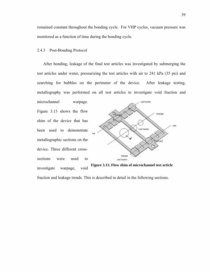
Figure 3.13 shows the flow
shim of the device that has
been used to demonstrate
metallographic sections on the
device. Three different cross-
sections were used to
investigate warpage, void
fraction and leakage trends. This is described in detail in the following sections.
Figure 3.13. Flow shim of microchannel test article
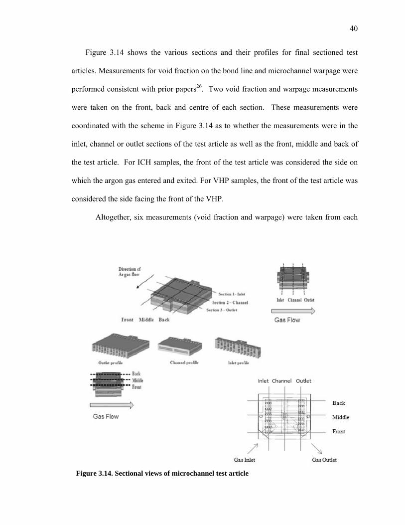
40
Figure 3.14 shows the various sections and their profiles for final sectioned test
articles. Measurements for void fraction on the bond line and microchannel warpage were
performed consistent with prior papersX
26.X Two void fraction and warpage measurements
were taken on the front, back and centre of each section. These measurements were
coordinated with the scheme in Figure 3.14 as to whether the measurements were in the
inlet, channel or outlet sections of the test article as well as the front, middle and back of
the test article. For ICH samples, the front of the test article was considered the side on
which the argon gas entered and exited. For VHP samples, the front of the test article was
considered the side facing the front of the VHP.
Altogether, six measurements (void fraction and warpage) were taken from each
Figure 3.14. Sectional views of microchannel test article
41
section of each test article for a total of 18 measurements per test article. A total of six
samples were sectioned; three ICH-bonded samples and three VHP-bonded samples.
Consequently, a total of 108 measurements were taken for both void fraction and
warpage measurements. Statistical analyses were performed to assess whether the means
of the two sets of samples were statistically different.
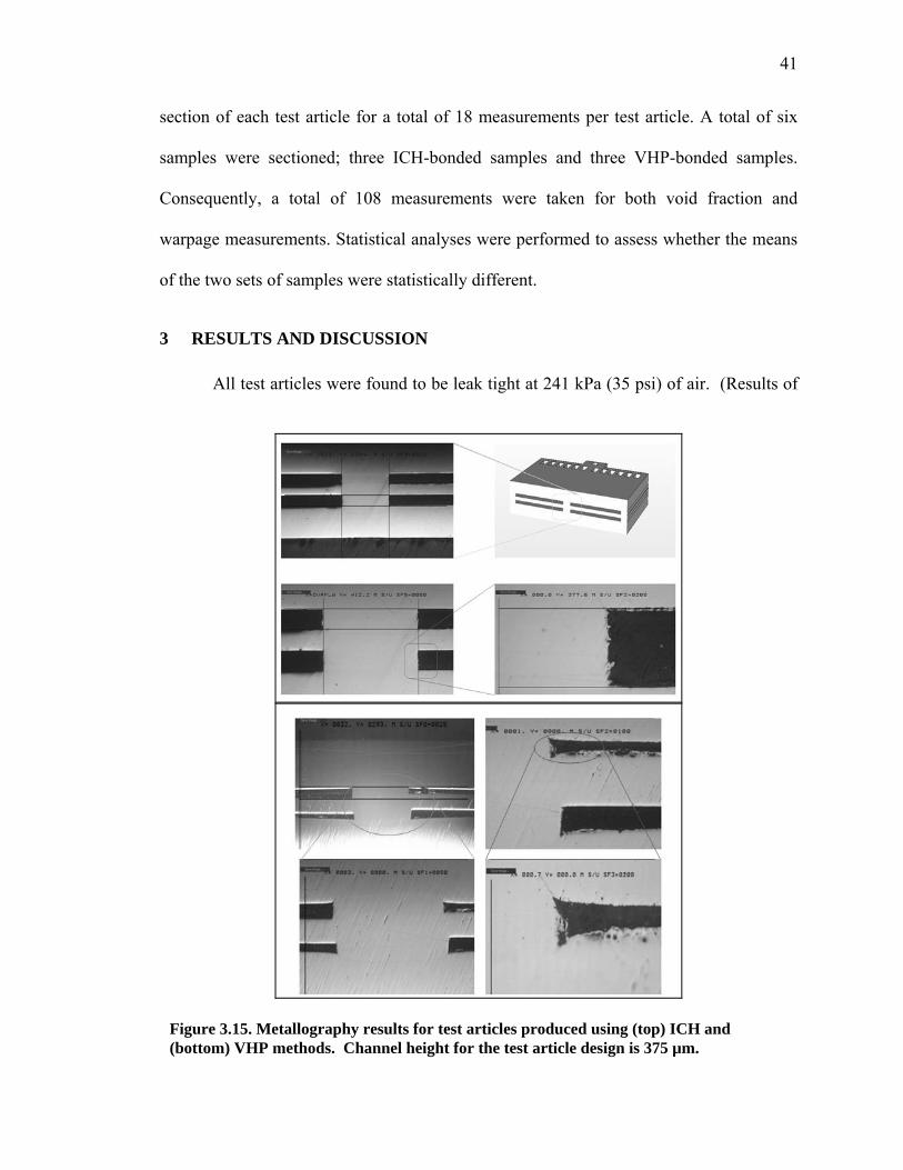
3 2BRESULTS AND DISCUSSION
All test articles were found to be leak tight at 241 kPa (35 psi) of air. (Results of
Figure 3.15. Metallography results for test articles produced using (top) ICH and (bottom) VHP methods. Channel height for the test article design is 375 µm.

42
leakage tests are given in Appendix C.)
Results from metallographic sectioning
showed that microchannel warpage
within the ICH test articles was much
lower than in VHP test articles. Figure
3.15 shows archetypal micrographs
within test articles produced using ICH
and VHP protocol, respectively. In
general, VHP-processed samples
show greatly deformed microchannel
geometries when compared with
respective ICH samples.
Figures 3.16 and 3.17 provide
a quantitative comparison of
warpage in the ICH and VHP test
articles. Test article location refers to the front, middle, and back regions of inlet,
channel, and outlet cross-sections (defined based on Figure 3.14). For comparison
purposes, all warpage measurements were taken on the same 1 mm spans within the same
regions of the test articles. Average warpage within ICH samples is 1.4% ± 0.7%
compared with VHP samples at 12.49% ± 1.48%. The ICH results are excellent. Prior
heat exchanger effectiveness studies have shown that for channels of this dimension,
channel variations below 5% have very little effect on heat exchanger effectiveness while
variations of 20% can require as much as 50% increase in heat exchanger size27.
Figure 3.16. Warpage in ICH samples
Figure 3.17. Warpage in VHP samples

43
It is important to note that the deformation in Figure 3.15 (bottom) is not
indicative of creep which is further substantiated by the results in Figure 3.12 which were
produced at the same bonding temperature, pressure and time at bonding temperature.
ICH samples compare favorably with test samples in Figure 3.12 produced by VHP
(warpage of 2.66% ± 1.8%). The differences between Figures 3.12 and 3.15 (bottom) are
the rates of heating and cooling. Therefore, it is expected that these deformations are due
to larger thermal gradients caused by the VHP protocol. This is explained below.
Inside the VHP during heating, heat is transferred from resistive heating elements
to the surface of the test article by radiation and then to the middle of the test article by
conduction. Heat is conducted over a distance greater than 25 mm. By contrast, in the
ICH protocol, heat is transferred from the argon gas to all internal surfaces and then to
the middle of the adjacent mass. In the case of a microchannel surface, the distance to
the middle of a microchannel fin is roughly 0.187 mm. Therefore, the conduction
distance in the ICH protocol is less than 1/100th the conduction distance in the VHP
protocol. When the heating (or cooling) rate is increased, the conductive heat transfer
becomes a bottleneck in the heat transfer process causing a buildup of energy and,
consequently, an ever larger thermal gradient. In the VHP, this buildup happens at much
slower heating rates than in the ICH method.

44
Figure 3.18 shows cross-sections of ICH and VHP samples prepared with an aqua
regia etch. The cross-section shows large equiaxed grains typical of a long heat treatment
with bondlines having no void fraction. Average percentage void fraction within ICH
samples was 2.32% ± 0.69% compared with VHP samples at 0.18% ± 0.26% indicating a
small increase in the number of voids within ICH samples. This difference is likely due to
the effects of inert gas leakage across the bondline during ICH processing.
Further, some interesting trends were found in the void fraction data for the ICH
samples. Figure 3.19 is a 3D representation of the void fraction data from sections taken
from similar regions of the ICH and VHP test articles. Noticeable in Figure 3.19 (left) is
Figure 3.19. 3D representation of average % void fractions in ICH (left) and VHP (right ) in different regions.
Figure 3.18. Cross sections of ICH(left) and VHP (right ) using aqua regia etch
375 µm
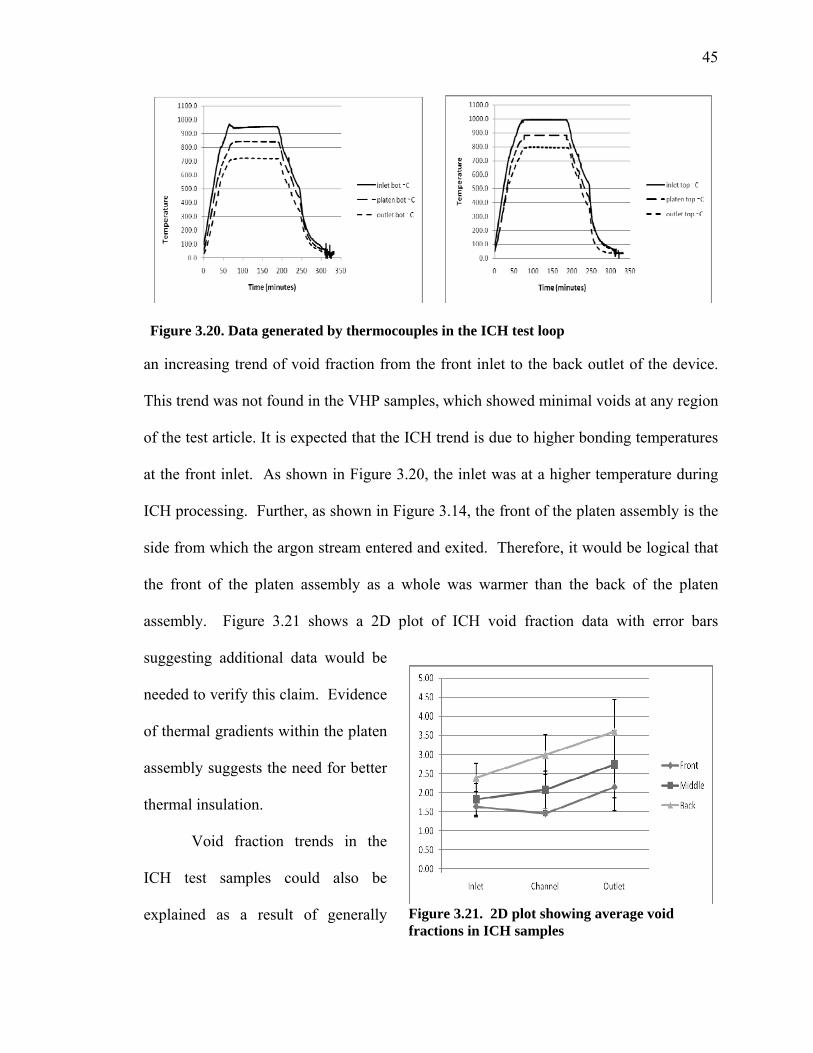
45
an increasing trend of void fraction from the front inlet to the back outlet of the device.
This trend was not found in the VHP samples, which showed minimal voids at any region
of the test article. It is expected that the ICH trend is due to higher bonding temperatures
at the front inlet. As shown in Figure 3.20, the inlet was at a higher temperature during
ICH processing. Further, as shown in Figure 3.14, the front of the platen assembly is the
side from which the argon stream entered and exited. Therefore, it would be logical that
the front of the platen assembly as a whole was warmer than the back of the platen
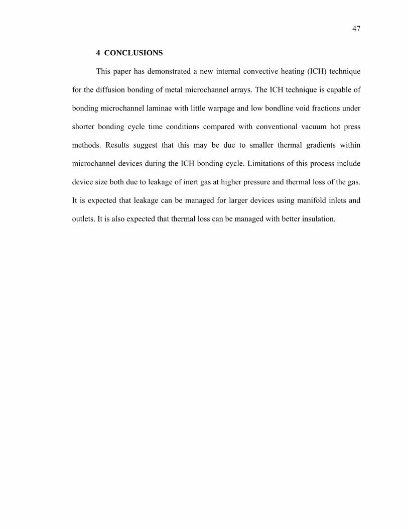
assembly. Figure 3.21 shows a 2D plot of ICH void fraction data with error bars
suggesting additional data would be
needed to verify this claim. Evidence
of thermal gradients within the platen
assembly suggests the need for better
thermal insulation.
Void fraction trends in the
ICH test samples could also be
explained as a result of generally
Figure 3.20. Data generated by thermocouples in the ICH test loop
Figure 3.21. 2D plot showing average void fractions in ICH samples

46
poorer parallelism within the ICH platen assembly stack than in the VHP. The ceramic
insulating blocks that were positioned above and below the ICH platen assembly were
difficult to machine. Any out-of-parallelism could have led to poor stress distribution
within the test article. However, this is a less likely explanation than the temperature
gradient explanation above since pressure sensitive films were used to check the
parallelism between platens and the test articles prior to bonding.
Figure 3.22 shows the thermal profile generated by the thermocouple placed in
the graphite block during
the VHP bonding cycle. A
comparison of Figures
3.20 and 3.22 shows that
the average bonding
temperature of the ICH
test articles (represented
by platen top and platen
bottom) were lower than
those of the VHP test articles. This would explain the generally higher void fraction on
the bondline of the ICH test articles. Ramp up rates were nearly equal roughly 17oC/min
and the ramp down rate was nominally 15oC/min. Noticeable in both graphs is an
increase in cooling rate below 500oC. In the case of the ICH process, this was the
temperature at which the insulation was removed. For the VHP case, helium was
introduced at this temperature.
Figure 3.22. Thermocouple data from VHP final conditions
47
4 CONCLUSIONS
This paper has demonstrated a new internal convective heating (ICH) technique
for the diffusion bonding of metal microchannel arrays. The ICH technique is capable of
bonding microchannel laminae with little warpage and low bondline void fractions under
shorter bonding cycle time conditions compared with conventional vacuum hot press
methods. Results suggest that this may be due to smaller thermal gradients within
microchannel devices during the ICH bonding cycle. Limitations of this process include
device size both due to leakage of inert gas at higher pressure and thermal loss of the gas.
It is expected that leakage can be managed for larger devices using manifold inlets and
outlets. It is also expected that thermal loss can be managed with better insulation.

48
B4 SUMMARY
The objective of our research was the development of an internal convective
heating (ICH) method for reducing the bonding cycle time within the diffusion bonding
of arrayed microfluidic devices. Preliminary research investigated the leakage and
thermal requirements for diffusion bonding microchannel arrays via ICH and
substantiated that the costs associated with the ICH of small devices are manageable. It is
suggested that this can further be improved through the recycling of the inert gas and
recuperation of the waste heat.
Further, the method of ICH was successfully demonstrated to reduce the cycle
time in diffusion bonding techniques compared to traditional VHP methods. The data
generated from six bonded samples proved that the ICH protocol will allow faster heating
and cooling than VHP protocol. Larger thermal gradients were suggested as the cause for
microchannel warpage in the VHP based on available data.
Several suggestions are made for improvement of the ICH method. It is expected
that the ICH method would perform better within a furnace enclosure. This would not
only provide better isolation from the ambient but provide better thermal insulation and
better safety for the users. Also, it is expected that there may be higher levels of oxide
inclusions to go along with higher void fractions within ICH samples. Forming gas could
be used to replace the inert gas to perhaps reduce voids and oxides.
49
APPENDIX A
LITERATURE REVIEW
Microlamination is a commonly used technique for the manufacturing of bulk
microfluidic devices. It inlvoles patterning, registration and diffusion bonding. Various
techniques have been used for the pattering of fluid layers. Good feature resolutions can
be achieved with photochemical etching. The laminae can be etched either single-sided or
double-sided to achieve complex cavity shapes. Direct-writing methods like laser
machining offer higher flexibility in the production of substrates compared to
photochemical etching. Stamping of patterns are an alternative to laser machining for
mass production, if channel features are not too small. High precision is required in the z-
axis for metals. This is controlled by cold rolling process, which is traditionally known
for precise, high-volume production (e.g. process is used to make shim stock). In a
typical microchannel array, the lateral patterns on laminae are much larger requiring less
precision. For the patterning of very complex channel features in metallic substrates,
fabrication methods like electrochemical micromachnining (ECMM) or electro discharge
micromachining (EDMM) could be of potential interest. Wire-EDM is capable of cutting
hundreds of layers at the same time by stacking up the substrates. After patterning and
cleaning of the individual fluidic layers the bonding process follows.
Diffusion bonding is commonly used to join metallic and ceramic structures. A
critical step during the bonding of the patterned layers is the proper alignment and
registration of the layers relative to each other. Commonly, alignment of the layers is
achieved with pins and precise pinholes in the layers. Thomas and Paul have shown an
50
innovative alignment technique by using the difference in thermal expansion between
fixture and laminae. During diffusion bonding laminae are heated up to bonding
temperature under an applied bonding pressure and held at these conditions for a period
of time necessary to join the layers to a monolithic device due to solid state diffusion.
Insufficient bonding conditions can lead to poor bonding and leakage while too great of
bonding conditions can lead to deformed or collapsed channel features.
4BMATERIALS
The application portfolio of bulk microfluidic devices requires that the materials
used have thermal, chemical and physical properties of more traditional engineering
materials such as metals or ceramics with high melting temperatures and corrosion
resistance. Therefore, most commonly used materials are stainless steel, copper,
aluminum alloys, titanium, and many others. For high-temperature applications in
microreactors, ceramics have been successfully implemented. Other high temperature
materials like aluminide foils have been investigated by Paul and Alman et al. for the
application in microlaminated high-temperature heat exchangers.
5BDIFFUSION BONDING
Many researchers have used diffusion bonding to convert stacks of microchannel
laminae into bulk microfluidic devices. Diffusion bonding of materials in the solid state
is a process for making a monolithic joint through the formation of bonds at atomic level,
as a result of closure of the mating surfaces.
The principal parameters activating diffusion bonding are bonding temperature,
bonding pressure and processing time. Between temperature and pressure a hyperbolic
51
relation is recommended to yield sound bonds. Bonding at higher temperatures needs less
pressure than bonding at lower temperatures. The bonding process takes place at
temperatures below the melting temperature Tm of the lowest melting material, typically
at 0.5-0.7 Tm. The pressure application is such, that macro-deformation of the joined
parts is not reached, although increasing the pressure could improve the bonding strength.
Typical pressure ranges are 5-10 MPa for carbon steels, 7-12 MPa for stainless steels and
3-7 MPa for aluminum alloys. An optimal bonding pressure is approximately equal to the
yield strength of the workpieces at the bonding temperature. Where dissimilar materials
are to be joined, the choice of bonding pressure is decided by the weaker of the two
materials.
Another critical factor which defines the success of any diffusion bonding cycle is
the processing time. The processing time is related to the temperature and pressure
parameters used in the bonding cycle. Also, between temperature and pressure a
hyperbolic relation is recommended to yield sound bonds. Bonding at higher temperature
means the furnace requires more time to heat up, but requires lesser bonding pressure for
a lesser time period. On the other hand, bonding at a lower temperature reduces the time
on the ramp up, but may mean exposure to pressure for a longer period of time, which in
turn results in channel deformation. The bonding time can vary depending on the applied
temperature and pressure from several minutes to several hours. An indirect indication
that a diffusion process is complete is the ultimate strength of the bond which should be
ideally the same as the parent material. The strength of the bond is proportional to the
square root of the bonding time, which is characteristic for any diffusion-controlled
process. The quality of diffusion bonded joints can be evaluated by using a wide range of
52
techniques. These include metallography, ultrasonic inspection and the use of mechanical
testing procedures such as tensile, impact and lap shear tests. Mechanical testing
procedures like tensile testing have been reported as reliable methods for the assessment
of bonding quality. However, these methods are not readily applicable to sheet material
structures and metallographic techniques can be used by analyzing the fraction of
interfacial voids.
Increased surface roughness increases the volume fraction of voids at the bonding
interface decreasing the bonding strength. It is also understood that an increased
temperature reduces the yield stress of the materials and activates the diffusion and
mobility of atoms in the lattice. When both pressure and temperature are applied together,
the bonding process can be accelerated.
Vacuum hot presses (VHP) are typically used to implement diffusion bonding
protocols for microchannel devices and provide reasonable protection from oxide films
and voids in bonded portions. It is used in cases of subjecting materials to high pressing
forces over large work areas under high vacuum or inert gas environment at elevated
temperatures. Pressure uniformity can be challenging. Further, the VHP often has been
undesirably large, having bulky construction with its utilizable enclosed work area
disproportionately small to the size of the enclosure or the associated press apparatus.
Consequently, the capital expense has sometimes been so large as to impede growth in
technology of microchannel devices. Further, the hydraulic vacuum hot press is not
always an appropriate machine tool for production of diffusion bonded devices. Finally,
the vacuum hot press requires batch operation which restricts the throughput.

53
6BALTERNATE TECHNIQUES
In the past, numerous microchannel based reactors, heat exchangers, and
separators within the context of basic and applied research projects have been developed
and fabricated, where unit cost is unimportant relative to other factors such as
performance, weight, and size. As the need for lighter and/or stronger materials has
advanced, interest has heightened in the technology of metal pressing, compacting and
joining materials for the fabrication of parts and in metal treating such as, for example,
diffusion bonding, powder metallurgy, vacuum brazing and thermo-mechanical
processing of materials. The efficiency of these techniques is defined by the factors of
cycle time, cost of operation and size. Some of the prior bonding techniques and their
efficiency are discussed in this section.
Some of the other alternatives to diffusion bonding include brazing, welding and
shrink fitting. While brazing can provide a metallurgical bond, the diffusion of
undesirable components such as flux materials from the brazing composition into the
adjoining bodies may weaken the surrounding alloys or cause grain boundary attack.
These are extremely undesirable for microchannel devices used for heat and mass transfer
applications. Brazing and welding can reduce strength by causing re-crystallization of
cold-worked metals, averaging of precipitation hardened alloys, and reversing the
transformation hardening in some alloys. In steels, martensitic structure may transform
back to softer austenite. Thus, the method of pressure welding is advantageous when the
process is desired to be automated. However, this method is inept when the eccentricity
between the bodies to be bonded is large . Also, welding is not effective when the bodies
have complex configurations, which is usually the case with microchannel structures.
54
Also, the shrink fitting process relies on a tight physical contact to frictionally hold the
bodies and is not as strong as either brazing or diffusion bonding as it does not provide a
strong metallurgical bond. Bond strengths need to be extremely high as these devices
undergo high pressures due to the fluids flowing through them.
A prior diffusion bonding technique avoided the usage of an external ram for the
application of pressure during the bonding cycle. As mentioned earlier, Thomas and Paul
designed an approach for precise alignment of multiple layers by differential thermal
expansion for use in the microlamination process. This process relied upon a positive
difference between thermal expansion coefficients of the sub-assembly material
compared to the clamping device material to generate the pressure required for bonding
at elevated temperatures.
Ultrasonic bonding techniques have also been used in the past, but to a less degree
of success due to economic reasons. The super plastic forming (SPF) and diffusion
bonding (DB) process is well documented and has been in use in the industry for many
years. Conventional compression diffusion bonding uses the force between the opposite
die surfaces of the forming press at elevated temperature to achieve intimate contact and
pressure between two or more mating surfaces of metal.
7BOBJECTIVE
This project is aimed at creating new capabilities for the low-cost rapid
production of microchannel reactors by addressing one of the longest and most costly
steps of traditional lamination processes – the bonding step. Heating and cooling rates in
furnace bonding processes are usually limited by the need to minimize thermal gradients
within the assembly (shim stack) being bonded. Rapid heating of the assembly by

55
external heating and intra-assembly conduction leads to significant thermal gradients
within the assembly, which can cause shim deformation, channel obstruction, and
residual mechanical stresses within the finished part. These mechanical considerations
limit the heating/cooling rate to about 5 ºC per minute depending upon the size of the hot
press and the size of the device being bonded. For bonding cycles that require
temperatures around 1000 ºC, this represents a very long duration during ramp-up. This
problem is further compounded as the size of the bonded device increases. Since the lead
time is directly proportional to the cost of the cycle, we decided to target minimizing of
the cycle time to significantly reduce the costs of producing such microchannel devices.
None of the prior art examined addresses the issue of joining of metals using diffusion
bonding at a faster rate, by keeping the ramp-up and ramp-down rates to an extremely
low level.
We propose that the internal convective heating (ICH) bonding technique can
provide the assembly with rapid heat input while minimizing thermal gradients within the
assembly, along with increasing the ramp up/ramp down rates. As compared to traditional
diffusion bonding methods, it is conceivable that internal convective heat could bring the
system up to the bonding temperature in a lot less time depending upon device and
process constraints such as thermal gradients allowable within the stack. Heating and
cooling times on this order should lead to a significant cycle time reduction as compared
to the vacuum hot press.
The ramp up/down rates on the ICH are significantly higher than those on the
VHP. The device will be convectively heated to around 10000 C, which is the standard
bonding temperature for stainless steel; the material used for our microchannel device.

56
The constant temperature region is where the bonding pressure is applied and diffusion
bonding of the device takes place. One of the challenges of the ICH approach is the
potential for gas leakage during bonding. Too high of a leakage rate could factor into the
economics as well as the safety of the process. To deliver the necessary heat at proper
flow rates, we designed and manufactured a thermal system (a microchannel heat
exchanger) which heats the convective fluid and controls the heating and cooling rates of
the entire system.

57
APPENDIX B
10BTEST SETUP
Figure B1 shows the conceptual description of the ICH test loop with cross marks
representing the spots where thermocouples were placed. Ultra high purity argon was
supplied to the system using a gas tank. The required flow rates were provided using a
calibrated mass flow controller which has a closed loop control system which was given
an input signal that it compares to the value from the mass flow sensor and adjusts the
proportional valve accordingly to achieve the required flow. The flow rate is specified as
a percentage of its calibrated full scale flow and is supplied to the MFC as a voltage
signal. A pressure sensor was also used to provide an estimate of the back pressures in
the system. The argon gas was then supplied to the inconel heat exchanger described
earlier. Swagelok fittings were used to connect the gas pipe to the inconel tubing. A K-
type thermocouple was placed in a hole drilled in the outlet of the heat exchanger. The
fire rod heaters in the heat exchanger were connected to the PID controller to control and
maintain the temperature. A proportional integral derivative (PID) controller attempts to
correct the error between a measured Hprocess variableH and a desired Hset point H by
calculating and then outputting a corrective action that can adjust the process
accordingly. The desired ramp rates were provided to the system using this PID
controller.
17BPLATEN ASSEMBLY THERMOCOUPLE PLACEMENTS:
The figure shows the areas where thermocouples were placed in the platen
assembly. Omega’s quick disconnect thermocouples with Miniature Connectors are high
Figure B1. Conceptual ICH diagram with thermocouple placements and PID loop
58
quality, economical thermocouple probes. They feature a glass filled nylon connector
which is rated for temperatures up to 220°C (425°F). The probes are available in with
diameters as small as 0.25mm (0.010 inches) and as large as 3mm (0.125 inches).
KMQIN-032U-6 type thermocouple with diameter of 0.032” was used in our
experiments.
Type K (chromel–alumel) is the most commonly used general purpose
thermocouple. It is inexpensive and, owing to its popularity, available in a wide variety of
probes. They are available in the −200 °C to +1350 °C range. 6 such thermocouples were
labeled and placed at different spots in the platen assembly to get an estimate of the
actual temperatures in the device. In the flow loop, 4 of these were placed at the inlet and
outlet tubing on both the top and bottom platen. 1/16” holes were drilled in the platen
assembly near the test article on the platens and two thermocouples were placed on these
to get a reasonable estimate of the temperature on the device. These two thermocouples
were not in the flow loop; instead they were monitoring the temperature in the metal. The
feedback from these thermocouples was received by data acquisition software which
directly provides the data to the computer for analysis. The thermocouple data is going to
be critical because the any temperature differences at different zones will account for the
bond quality in that particular region in the test article. Before running the final ICH
cycle, it was critical to estimate the leakage rates in the flow loop. A high gas leakage
rate would result in heat losses as well as create a safety hazard. The leakage tests would
also provide us with the minimum clamping pressure required to prevent leakage from
the platen assembly.
59
For proof-of-principle testing, it was decided that the bonding pressure could be
supplied by the hydraulic subsystem of a vacuum hot press. This requires the internal
convective heating test stand to be set up adjacent to a VHP and operated within the work
envelope of the system. In the current test stand, the work envelope is constrained to a
maximum of a 75 mm diameter. During warm-up, the purpose of the clamping
mechanism is to provide enough pressure to keep the heat exchange gas from leaking out
between the shims. During the bonding cycle, the pressure is required for solid state
diffusion across faying surfaces. Typical pressures of 1000-1200 psi are required during
the bonding step. Heat losses through the system were a cause for concern in the ICH test
loop. We decided to use a ceramic insulation which would not only prevent heat loss but
also transmit the pressure from the hydraulic rams to the platens assembly.
21BMaterial description
Type ZIRCAL-95 Refractory Board is produced from a combination of natural
organic fibers and inert reinforcing fillers in a high density calcium silicate hydrate
matrix. Designed as a substitute for asbestos cement boards, ZIRCAL-95 is useful as
structural and electrical insulation in applications with temperatures to 1100°C (2000°F).
ZIRCAL-95`s surface is sanded smooth. It has a uniform consistency making it a useful
source for custom machined insulating parts.
22BFabrication
Zircal 95, 24”x 48” x 1” SS23-A. Zircal-95 has unique machining characteristics.
It is easily cut with hand held woodworking tools using slow cutting action. Operator will
notice the rate of material removal decreases as increased force and tool speed is applied.
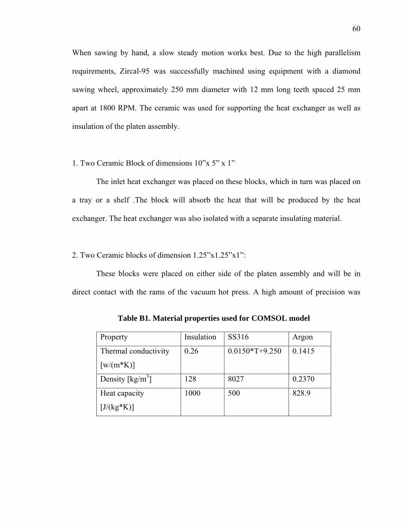
60
When sawing by hand, a slow steady motion works best. Due to the high parallelism
requirements, Zircal-95 was successfully machined using equipment with a diamond
sawing wheel, approximately 250 mm diameter with 12 mm long teeth spaced 25 mm
apart at 1800 RPM. The ceramic was used for supporting the heat exchanger as well as
insulation of the platen assembly.
1. Two Ceramic Block of dimensions 10”x 5” x 1”
The inlet heat exchanger was placed on these blocks, which in turn was placed on
a tray or a shelf .The block will absorb the heat that will be produced by the heat
exchanger. The heat exchanger was also isolated with a separate insulating material.
2. Two Ceramic blocks of dimension 1.25”x1.25”x1”:
These blocks were placed on either side of the platen assembly and will be in
direct contact with the rams of the vacuum hot press. A high amount of precision was
Table B1. Material properties used for COMSOL model
Property Insulation SS316 Argon
Thermal conductivity
[w/(m*K)]
0.26 0.0150*T+9.250
0.1415
Density [kg/m3] 128 8027 0.2370
Heat capacity
[J/(kg*K)]
1000 500 828.9
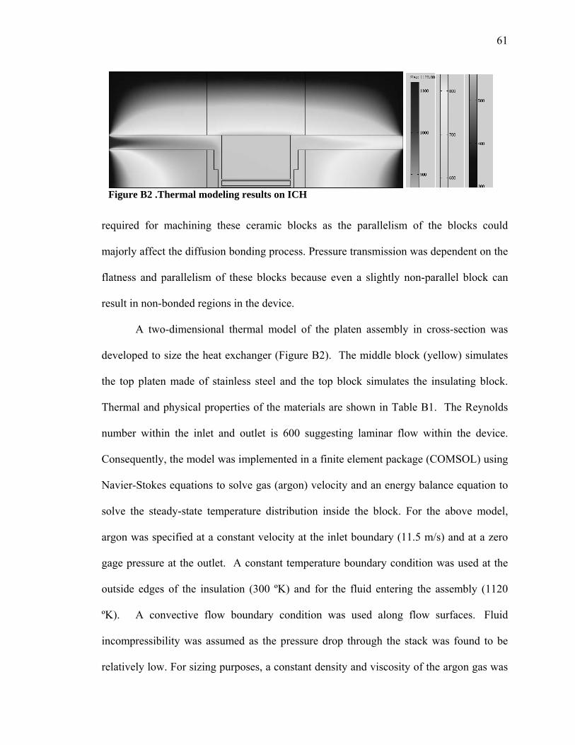
61
required for machining these ceramic blocks as the parallelism of the blocks could
majorly affect the diffusion bonding process. Pressure transmission was dependent on the
flatness and parallelism of these blocks because even a slightly non-parallel block can
result in non-bonded regions in the device.
A two-dimensional thermal model of the platen assembly in cross-section was
developed to size the heat exchanger (Figure B2). The middle block (yellow) simulates
the top platen made of stainless steel and the top block simulates the insulating block.
Thermal and physical properties of the materials are shown in Table B1. The Reynolds
number within the inlet and outlet is 600 suggesting laminar flow within the device.
Consequently, the model was implemented in a finite element package (COMSOL) using
Navier-Stokes equations to solve gas (argon) velocity and an energy balance equation to
solve the steady-state temperature distribution inside the block. For the above model,
argon was specified at a constant velocity at the inlet boundary (11.5 m/s) and at a zero
gage pressure at the outlet. A constant temperature boundary condition was used at the
outside edges of the insulation (300 ºK) and for the fluid entering the assembly (1120
ºK). A convective flow boundary condition was used along flow surfaces. Fluid
incompressibility was assumed as the pressure drop through the stack was found to be
relatively low. For sizing purposes, a constant density and viscosity of the argon gas was
Figure B2 .Thermal modeling results on ICH
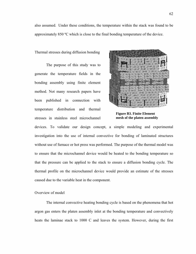
62
also assumed. Under these conditions, the temperature within the stack was found to be
approximately 850 ºC which is close to the final bonding temperature of the device.
18BThermal stresses during diffusion bonding
The purpose of this study was to
generate the temperature fields in the
bonding assembly using finite element
method. Not many research papers have
been published in connection with
temperature distribution and thermal
stresses in stainless steel microchannel
devices. To validate our design concept, a simple modeling and experimental
investigation into the use of internal convective for bonding of laminated structures
without use of furnace or hot press was performed. The purpose of the thermal model was
to ensure that the microchannel device would be heated to the bonding temperature so
that the pressure can be applied to the stack to ensure a diffusion bonding cycle. The
thermal profile on the microchannel device would provide an estimate of the stresses
caused due to the variable heat in the component.
23BOverview of model
The internal convective heating bonding cycle is based on the phenomena that hot
argon gas enters the platen assembly inlet at the bonding temperature and convectively
heats the laminae stack to 1000 C and leaves the system. However, during the first
Figure B3. Finite Element mesh of the platen assembly
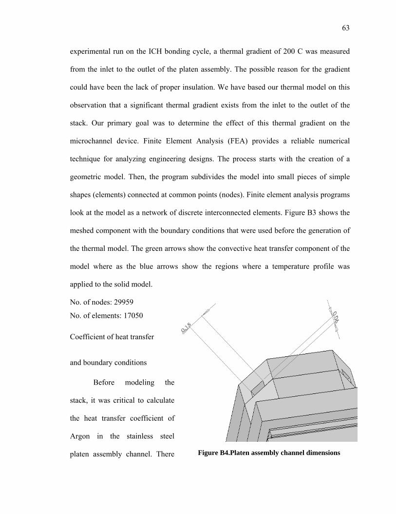
63
experimental run on the ICH bonding cycle, a thermal gradient of 200 C was measured
from the inlet to the outlet of the platen assembly. The possible reason for the gradient
could have been the lack of proper insulation. We have based our thermal model on this
observation that a significant thermal gradient exists from the inlet to the outlet of the
stack. Our primary goal was to determine the effect of this thermal gradient on the
microchannel device. Finite Element Analysis (FEA) provides a reliable numerical
technique for analyzing engineering designs. The process starts with the creation of a
geometric model. Then, the program subdivides the model into small pieces of simple
shapes (elements) connected at common points (nodes). Finite element analysis programs
look at the model as a network of discrete interconnected elements. Figure B3 shows the
meshed component with the boundary conditions that were used before the generation of
the thermal model. The green arrows show the convective heat transfer component of the
model where as the blue arrows show the regions where a temperature profile was
applied to the solid model.
No. of nodes: 29959
No. of elements: 17050
24BCoefficient of heat transfer
25Band boundary conditions
Before modeling the
stack, it was critical to calculate
the heat transfer coefficient of
Argon in the stainless steel
platen assembly channel. There Figure B4.Platen assembly channel dimensions

64
are numerous correlations for calculation of heat transfer coefficient in different heat
transfer modes, fluids, flow regimes, and under different thermo-hydraulic conditions.
Often, it can be estimated by dividing the thermal conductivity of the convection fluid by
a length scale. In our case, the heat transfer coefficient was calculated from the Nusselt
number (a dimensionless number).
Coefficient of heat transfer:
h = NuT. k/ Dh
Platen assembly channel dimensions
Width= 0.15 inches
Height: 0.06 inches
Dh = 0.00216
k= 0.0351 W/ m.K (Argon); NuT = 0.5322[5]
h= 8.64 W /m2K
Convection describes the heat transfer mechanism between a solid face and an
adjacent moving fluid (or gas). It involves the combined effects of conduction and the
moving fluid. Fluid particles act as carriers of thermal energy. A solid loses thermal
energy through a face with convection if the temperature of the face is higher than the
bulk temperature. The solid gains thermal energy if the temperature of the face is lower
than the bulk temperature. The temperature of an entity with a prescribed temperature
remains constant at all times. Depending on other thermal loads and restraints, the model
can lose or gain thermal energy at locations with prescribed temperatures.
The boundary conditions used for the development of the thermal model using
COSMOS flow works are as follows:
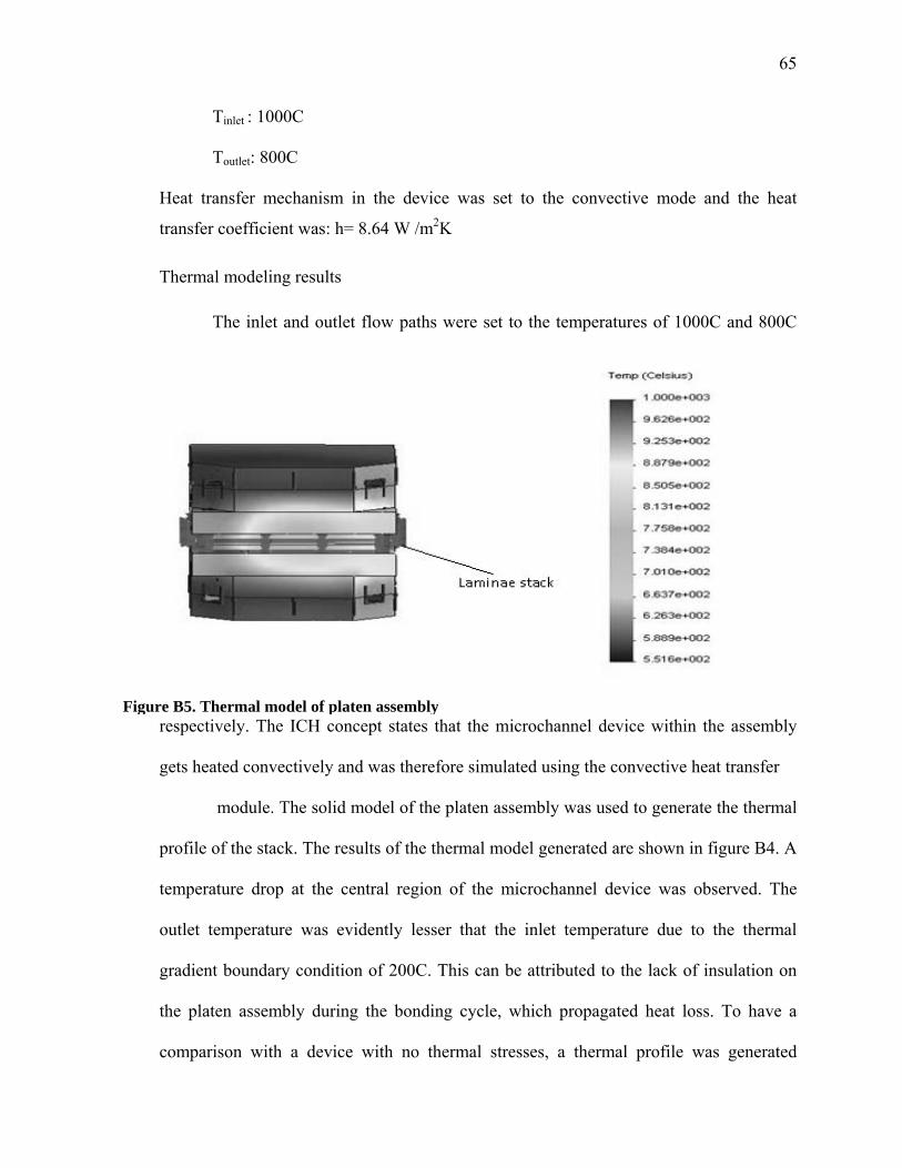
65
Tinlet : 1000C
Toutlet: 800C
Heat transfer mechanism in the device was set to the convective mode and the heat
transfer coefficient was: h= 8.64 W /m2K
26BThermal modeling results
The inlet and outlet flow paths were set to the temperatures of 1000C and 800C
respectively. The ICH concept states that the microchannel device within the assembly
gets heated convectively and was therefore simulated using the convective heat transfer
module. The solid model of the platen assembly was used to generate the thermal
profile of the stack. The results of the thermal model generated are shown in figure B4. A
temperature drop at the central region of the microchannel device was observed. The
outlet temperature was evidently lesser that the inlet temperature due to the thermal
gradient boundary condition of 200C. This can be attributed to the lack of insulation on
the platen assembly during the bonding cycle, which propagated heat loss. To have a
comparison with a device with no thermal stresses, a thermal profile was generated
Figure B5. Thermal model of platen assembly
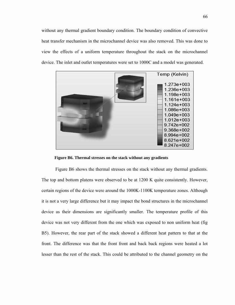
66
without any thermal gradient boundary condition. The boundary condition of convective
heat transfer mechanism in the microchannel device was also removed. This was done to
view the effects of a uniform temperature throughout the stack on the microchannel
device. The inlet and outlet temperatures were set to 1000C and a model was generated.
Figure B6 shows the thermal stresses on the stack without any thermal gradients.
The top and bottom platens were observed to be at 1200 K quite consistently. However,
certain regions of the device were around the 1000K-1100K temperature zones. Although
it is not a very large difference but it may impact the bond structures in the microchannel
device as their dimensions are significantly smaller. The temperature profile of this
device was not very different from the one which was exposed to non uniform heat (fig
B5). However, the rear part of the stack showed a different heat pattern to that at the
front. The difference was that the front front and back back regions were heated a lot
lesser than the rest of the stack. This could be attributed to the channel geometry on the
Figure B6. Thermal stresses on the stack without any gradients
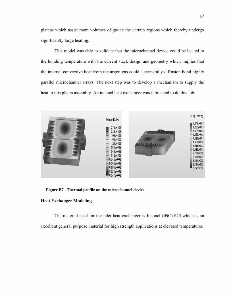
67
platens which assist more volumes of gas in the certain regions which thereby undergo
significantly large heating.
This model was able to validate that the microchannel device could be heated to
the bonding temperature with the current stack design and geometry which implies that
the internal convective heat from the argon gas could successfully diffusion bond highly
parallel microchannel arrays. The next step was to develop a mechanism to supply the
heat to this platen assembly. An inconel heat exchanger was fabricated to do this job.
19BHeat Exchanger Modeling
The material used for the inlet heat exchanger is Inconel (INC) 625 which is an
excellent general purpose material for high strength applications at elevated temperatures
Figure B7 . Thermal profile on the microchannel device

68
in oxygen atmospheres. An exploded view of the heat exchanger is shown in
Figure B8. As shown in the figure, the INC 625 heat exchanger at the inlet consists of a
centre block, a top and a bottom plate and some additional Inconel tubing. The centre
block has dimensions of 8.5”x4.5”x1.0”. Channels are machined on either side of the
centre block to allow for the passage of argon gas from two inlets to two outlets. In the
middle of the block are three 0.75” diameter through holes for placing nichrome heaters.
The heaters are each capable of transferring up to 1000 watts of thermal power at 1400K.
The channels on the centre block are covered at the top and bottom by two INC
625 plates (8.5”x4.5”x0.125”). The two inlets and two outlets of the heat exchanger are
connected to tube fittings. An estimate of the thermal requirements for the ICH system
can be made by considering the enthalpy of the thermal mass in the system and making
assumptions about heat losses. In our model, we are assuming that heat transfer to the gas
Figure B8. Exploded view of INC 625 Heat Exchanger
69
occurs from only one wall. This wall is held at a constant temperature of 1200K. The
constant temperature boundary condition is present when the duct has a constant wall
temperature in both the circumferential and the axial directions.
u = Q / A;
Where,
Q is the volumetric flow rate and
A is the cross sectional area of channel
u = 0.000416 m3/sec / 0.0000772 m2
= 5.388 m/sec
The thermodynamic properties of argon gas were calculated at different
temperatures ranging from 298-1200K. The values of molecular weight, density, specific
heat, viscosity and thermal conductivity of argon at 298, 748, and 1200K are provided in
Table 2. In order to design a plate-type heat exchanger capable of meeting these
requirements, the mass flow rate and an estimation of the convective heat transfer
coefficient is needed.
Coefficient of heat transfer and mass flow rate calculations
The convective heat transfer coefficient for this application can be estimated by,
h = NuT. k/ Dh (2)
Where,
NuT ~ Nusselt number at constant wall temperature of 925 oC
Dh ~ hydraulic diameter
k ~ thermal conductivity of argon
h ~ coefficient of heat transfer

70
Nusselt number for fully developed laminar flow in rectangular ducts with heat
transfer through one wall is 0.5322 [28].
The hydraulic diameter is given by,
Dh = 4ab/ (2*(a+b)) (3)
Where,
a and b are channel height and width respectively
Dh = 0.00543m
The mass flow rate can be calculated as: m = ρ .Q
(4)
Where,
ρ ~ density of argon gas
Q ~ volumetric flow rate
Table B2. Thermodynamic properties of argon
Temperature, K 298 748 1200
Molecular weight (MW), kg/mol 0.039 0.039 0.039
Density (ρ), kg/m3 1.633 1.024 0.526
Specific heat (Cp), kJ/kg.K 0.520 0.520 0.520
Viscosity (η), kg/m.sec (105) 2.26 4.44 5.99
Thermal conductivity (k),
W/m.K
0.01769 0.0351 0.048

71
The volumetric flow rate for heating incoming argon gas to 1200K according to
model developed previously is 25lt/min. Hence, this will be the volumetric flow rate at
which the room temperature argon must enter the Inc 625 heat exchanger.
25 lt/min =0.000416 m3/sec
The coefficient of heat transfer and mass flow rate was calculated using the equations
mentioned earlier and the values obtained are shown in table B3.
27BCalculation of Reynolds number
In fluid mechanics, the
Reynolds number is the ratio of
inertial forces to viscous forces
and consequently it quantifies the
relative importance of these two
types of forces for given flow
conditions. Thus, it is used to
identify different flow regimes, such as laminar or turbulent flow.
Re= (u. Dh)/ ν
Where, u is the velocity of the gas; ν is the kinematic fluid viscosity
Table B3. Coefficient of heat transfer and mass flow rate
Temperature(K) 298 748 1200
Heat Transfer Coefficient (W /m2K) 1.832 3.370 4.702
Mass flow rate(kg/sec) 0.00067
0.00042
.00021
0
200
400
600
800
1000
1200
1400
0 250 500 750 1000 1250 1500 1750 2000 2250
Reynolds number
Tem
pera
ture
(K)
Figure B9 .Variation of Reynolds number with temperature

72
ν = η / ρ where, η, ρ are viscosity and density of argon gas respectively
Also,
u = Q / A where,
Q is the volumetric flow rate and
A is the cross sectional area of channel machined in the heat exchanger.
u= 0.000416(m3/sec)/0.0000772 m2 = 5.388 m/sec
The plot of Reynolds number against the temperature is shown in fig.B9.The values of
Reynolds number suggests laminar flow at high temperatures. A Reynolds number
greater than 2300 lies in the turbulent flow region. In our case, this around the 400-600
range.
28BThermal model of heat exchanger
A thermal model based on the parameters of argon gas, heat transfer coefficient,
and the channel dimensions of the heat exchanger was generated. The purpose of the
thermal model was to determine if the surface area of the channel would be sufficient to
heat the argon gas coming in at room temperature to the bonding temperature of the
device. Figure B10 shows the distance traveled by the gas in the channel of the heat
exchanger before it gets heated to the bonding temperature of the stack which is roughly
1200K. The results showed that the argon gas was heated to greater 1150K within a
distance equal to approximately twice the channel height (6 mm from inlet).The heat
distribution proves that the channel area provided in the heat exchanger would be
sufficient for raising the gas temperature to 1200K from room temperature.
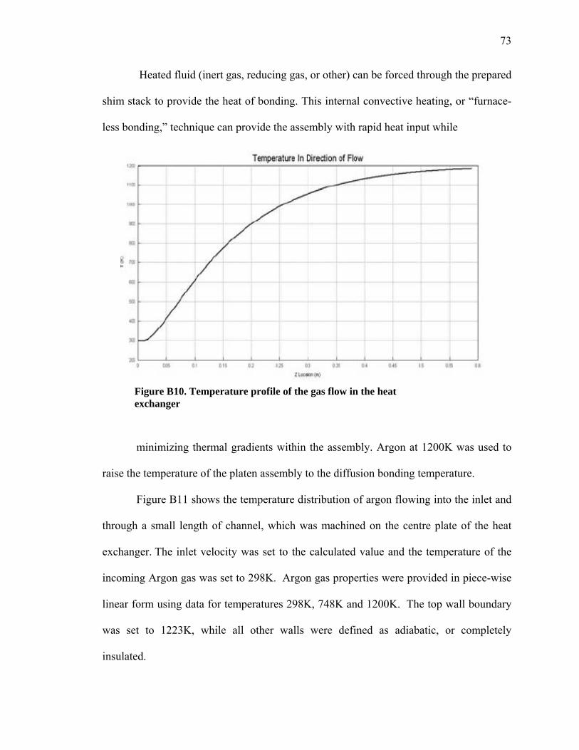
73
Heated fluid (inert gas, reducing gas, or other) can be forced through the prepared
shim stack to provide the heat of bonding. This internal convective heating, or “furnace-
less bonding,” technique can provide the assembly with rapid heat input while
minimizing thermal gradients within the assembly. Argon at 1200K was used to
raise the temperature of the platen assembly to the diffusion bonding temperature.
Figure B11 shows the temperature distribution of argon flowing into the inlet and
through a small length of channel, which was machined on the centre plate of the heat
exchanger. The inlet velocity was set to the calculated value and the temperature of the
incoming Argon gas was set to 298K. Argon gas properties were provided in piece-wise
linear form using data for temperatures 298K, 748K and 1200K. The top wall boundary
was set to 1223K, while all other walls were defined as adiabatic, or completely
insulated.
Figure B10. Temperature profile of the gas flow in the heat exchanger
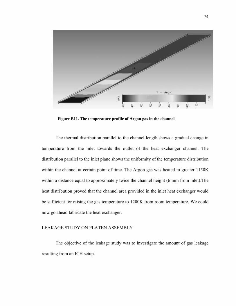
74
The thermal distribution parallel to the channel length shows a gradual change in
temperature from the inlet towards the outlet of the heat exchanger channel. The
distribution parallel to the inlet plane shows the uniformity of the temperature distribution
within the channel at certain point of time. The Argon gas was heated to greater 1150K
within a distance equal to approximately twice the channel height (6 mm from inlet).The
heat distribution proved that the channel area provided in the inlet heat exchanger would
be sufficient for raising the gas temperature to 1200K from room temperature. We could
now go ahead fabricate the heat exchanger.
20BLEAKAGE STUDY ON PLATEN ASSEMBLY
The objective of the leakage study was to investigate the amount of gas leakage
resulting from an ICH setup.
Figure B11. The temperature profile of Argon gas in the channel
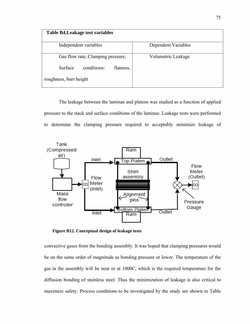
75
Table B4.Leakage test variables
Independent variables Dependent Variables
Gas flow rate, Clamping pressure,
Surface conditions: flatness,
roughness, burr height
Volumetric Leakage
The leakage between the laminae and platens was studied as a function of applied
pressure to the stack and surface conditions of the laminae. Leakage tests were performed
to determine the clamping pressure required to acceptably minimize leakage of
convective gases from the bonding assembly. It was hoped that clamping pressures would
be on the same order of magnitude as bonding pressure or lower. The temperature of the
gas in the assembly will be near or at 1000C, which is the required temperature for the
diffusion bonding of stainless steel. Thus the minimization of leakage is also critical to
maximize safety. Process conditions to be investigated by the study are shown in Table
Figure B12. Conceptual design of leakage tests

76
B4. The platens consist of an inlet and an outlet slot allowing for the entry and exit of
argon gas. Stainless steel tubing was TIG welded onto the inlet and outlet slots of each
platen. Holes were machined on the platens for pin alignment of the laminated shims.
29BLEAKAGE TEST SETUP
Figure B12 shows the shim assembly stacked in between the two platens, ready to
be leak tested. A mass flow controller and a flow meter were connected to the inlet of the
compressed air loop at close proximity to the vacuum hot press. A flow meter and a
pressure gauge were connected to the outlet stream of the platen assembly. The purpose
of the pressure gauge was to measure and vary the back pressure at the outlet of the flow
loop. Finally, the assembly was clamped between the hydraulic rams of the vacuum hot
press. As a preliminary leak test, the platens were clamped together with a ‘C-clamp’.
The assembly was immersed in a beaker containing water, and pressure was applied to
check for bubbles. There was no bubble formation within the platens up to a pressure of
35 psi, indicating no leakage from the part. Before stacking, the shims were cleaned in a
solution of Citranox and water. Grease was removed by acetone followed by ethanol and
de-ionized water for removal of residues. The set of cleaned laminae were then
assembled and aligned with the slots provided on the bonded platen assembly using 1/16”
diameter alignment pins. For our final tests, the platen assembly was clamped between
the rams of the vacuum hot press and the pressure was kept at a minimum level. The
compressed air was turned on and passed through the platen assembly. The clamping
pressure was gradually increased using the pressure control panel on the vacuum hot
press. Volumetric flow rates at the outlet were measured with increasing clamping
pressure using the flow meter provided at the outlet shown in Figure B12.

77
APPENDIX C
RESULTS AND DATA COLLECTION
Devices bonded on the vacuum hot press were compared with those made using
the internal convective heating process. Metallographic sample preparation was used to
find the true structure of the sample. Metallographic specimens were mounted using
thermosetting resin and hardener mix. Thermosetting resins have been used in the past,
but modern epoxy is becoming more popular because reduced shrinkage during curing
results in a better mount with superior edge retention. After mounting, the specimen were
cut open using a diamond saw and polished to reveal the surface of the metal. The
specimen was successively ground with finer and finer abrasive sand paper. The ratings
were used from 180, 320, up to 600 grit. Metallographic metrics of warpage and void
fractions were used for data analysis and comparison. A brief description of methods to
calculate these are given below.
Warpage Calculations
Warpage is a distortion where the surfaces of the bonded part do not follow the
intended shape of the design. Warpage results from thermal stresses, which, in turn, is
caused by differential heating of material in the molded part.
Warpage is measured using the following relation,
W= ∆X/l
Where,
∆X is the channel deviation or deformation that has occurred and l is the length over
which that deformation has occurred.
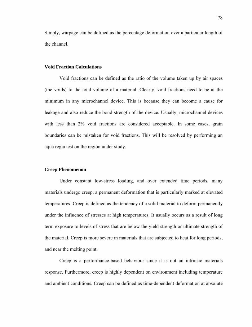
78
Simply, warpage can be defined as the percentage deformation over a particular length of
the channel.
Void Fraction Calculations
Void fractions can be defined as the ratio of the volume taken up by air spaces
(the voids) to the total volume of a material. Clearly, void fractions need to be at the
minimum in any microchannel device. This is because they can become a cause for
leakage and also reduce the bond strength of the device. Usually, microchannel devices
with less than 2% void fractions are considered acceptable. In some cases, grain
boundaries can be mistaken for void fractions. This will be resolved by performing an
aqua regia test on the region under study.
Creep Phenomenon
Under constant low-stress loading, and over extended time periods, many
materials undergo creep, a permanent deformation that is particularly marked at elevated
temperatures. Creep is defined as the tendency of a solid material to deform permanently
under the influence of stresses at high temperatures. It usually occurs as a result of long
term exposure to levels of stress that are below the yield strength or ultimate strength of
the material. Creep is more severe in materials that are subjected to heat for long periods,
and near the melting point.
Creep is a performance-based behaviour since it is not an intrinsic materials
response. Furthermore, creep is highly dependent on environment including temperature
and ambient conditions. Creep can be defined as time-dependent deformation at absolute

79
temperatures greater than one half the absolute melting. Creep is a relative phenomenon
which may occur at temperatures not normally considered high.
Since all mechanisms of steady-state creep are in some way dependent on
diffusion, we expect that creep rate will have this exponential dependence on
temperature. Creep occurs faster at higher temperatures. However, what constitutes a
high temperature is different for different metals.
Figures C1 and C2 show the metallographic examination of SS 316 shims bonded
at 1000 C and 950 C showed the creep damage distribution caused by the multiaxial
stresses in SS316 microchannels. This finding may have application in the design, life
prediction, and in-service evaluation of diffusion bonded stainless steel microchannel
devices. More figures in the appendix show the creep phenomenon caused due to stresses
at high temperatures.
Difference between Creep and Warpage
Figure C1. Creep mechanisms
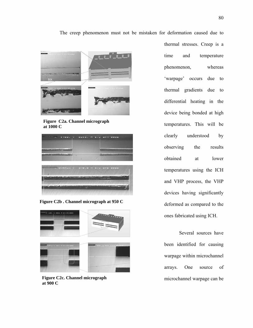
80
The creep phenomenon must not be mistaken for deformation caused due to
thermal stresses. Creep is a
time and temperature
phenomenon, whereas
‘warpage’ occurs due to
thermal gradients due to
differential heating in the
device being bonded at high
temperatures. This will be
clearly understood by
observing the results
obtained at lower
temperatures using the ICH
and VHP process, the VHP
devices having significantly
deformed as compared to the
ones fabricated using ICH.
Several sources have
been identified for causing
warpage within microchannel
arrays. One source of
microchannel warpage can be
Figure C2b . Channel micrograph at 950 C
Figure C2c. Channel micrograph at 900 C
Figure C2a. Channel micrograph at 1000 C
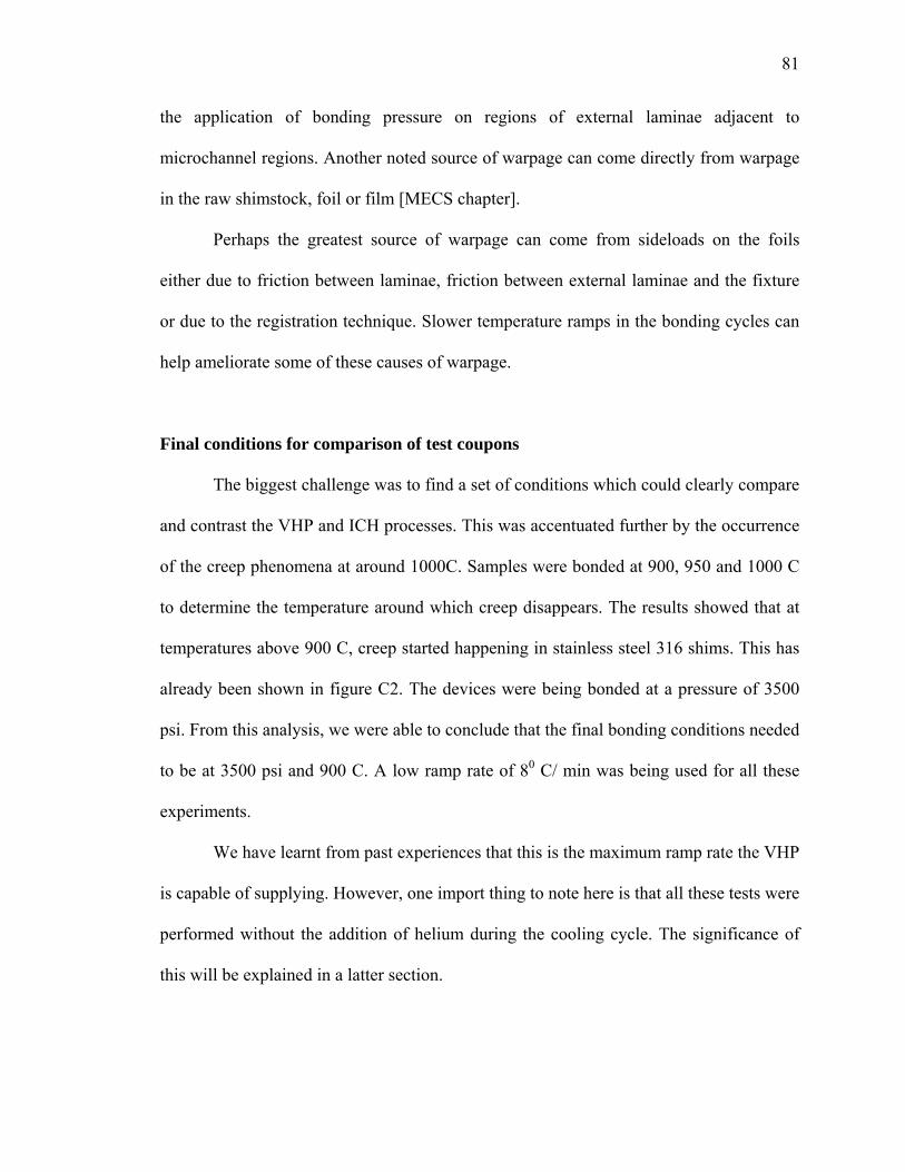
81
the application of bonding pressure on regions of external laminae adjacent to
microchannel regions. Another noted source of warpage can come directly from warpage
in the raw shimstock, foil or film [MECS chapter].
Perhaps the greatest source of warpage can come from sideloads on the foils
either due to friction between laminae, friction between external laminae and the fixture
or due to the registration technique. Slower temperature ramps in the bonding cycles can
help ameliorate some of these causes of warpage.
Final conditions for comparison of test coupons
The biggest challenge was to find a set of conditions which could clearly compare
and contrast the VHP and ICH processes. This was accentuated further by the occurrence
of the creep phenomena at around 1000C. Samples were bonded at 900, 950 and 1000 C
to determine the temperature around which creep disappears. The results showed that at
temperatures above 900 C, creep started happening in stainless steel 316 shims. This has
already been shown in figure C2. The devices were being bonded at a pressure of 3500
psi. From this analysis, we were able to conclude that the final bonding conditions needed
to be at 3500 psi and 900 C. A low ramp rate of 80 C/ min was being used for all these
experiments.
We have learnt from past experiences that this is the maximum ramp rate the VHP
is capable of supplying. However, one import thing to note here is that all these tests were
performed without the addition of helium during the cooling cycle. The significance of
this will be explained in a latter section.
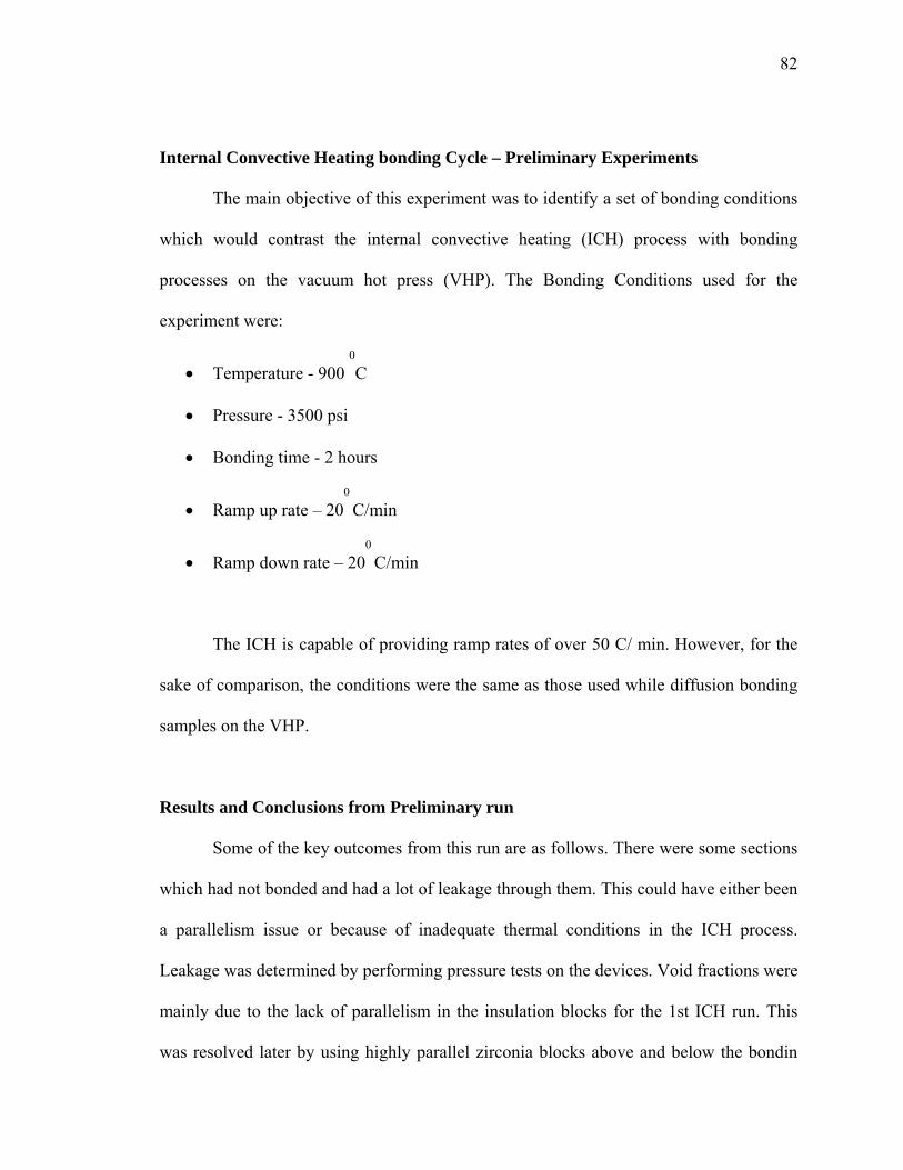
82
Internal Convective Heating bonding Cycle – Preliminary Experiments
The main objective of this experiment was to identify a set of bonding conditions
which would contrast the internal convective heating (ICH) process with bonding
processes on the vacuum hot press (VHP). The Bonding Conditions used for the
experiment were:
• Temperature - 900 0
C
• Pressure - 3500 psi
• Bonding time - 2 hours
• Ramp up rate – 200
C/min
• Ramp down rate – 200
C/min
The ICH is capable of providing ramp rates of over 50 C/ min. However, for the
sake of comparison, the conditions were the same as those used while diffusion bonding
samples on the VHP.
Results and Conclusions from Preliminary run
Some of the key outcomes from this run are as follows. There were some sections
which had not bonded and had a lot of leakage through them. This could have either been
a parallelism issue or because of inadequate thermal conditions in the ICH process.
Leakage was determined by performing pressure tests on the devices. Void fractions were
mainly due to the lack of parallelism in the insulation blocks for the 1st ICH run. This
was resolved later by using highly parallel zirconia blocks above and below the bondin
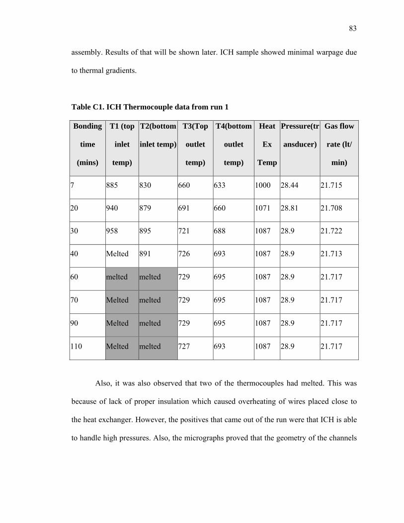
83
assembly. Results of that will be shown later. ICH sample showed minimal warpage due
to thermal gradients.
Table C1. ICH Thermocouple data from run 1
Also, it was also observed that two of the thermocouples had melted. This was
because of lack of proper insulation which caused overheating of wires placed close to
the heat exchanger. However, the positives that came out of the run were that ICH is able
to handle high pressures. Also, the micrographs proved that the geometry of the channels
Bonding
time
(mins)
T1 (top
inlet
temp)
T2(bottom
inlet temp)
T3(Top
outlet
temp)
T4(bottom
outlet
temp)
Heat
Ex
Temp
Pressure(tr
ansducer)
Gas flow
rate (lt/
min)
7 885 830 660 633 1000 28.44 21.715
20 940 879 691 660 1071 28.81 21.708
30 958 895 721 688 1087 28.9 21.722
40 Melted 891 726 693 1087 28.9 21.713
60 melted melted 729 695 1087 28.9 21.717
70 Melted melted 729 695 1087 28.9 21.717
90 Melted melted 729 695 1087 28.9 21.717
110 Melted melted 727 693 1087 28.9 21.717

84
was acceptable in terms of standards for microchannel devices (Figure C6). We had to
now take care of the parallelism issue and the thermal insulation problem.
Pressure tests
The test article was clamped to a pressure testing device using miniature clamps.
All tests were performed at room temperature and atmospheric pressure. A flow path was
created by cutting out a channel on silicone having the same dimensions of the test
article. The system was pressurized using a hand pump. Snoop fluid was applied to check
for leakage in suspected areas.
The devices were checked for internal and external leaks. A pressure of 25psig
was applied to the system. The circled regions show bubbles in the figure at the regions
of maximum leakage. It was observed that the loss of pressure in the system was
Figure C3. Pressure test results
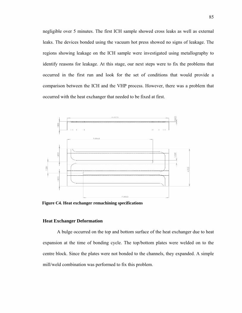
85
negligible over 5 minutes. The first ICH sample showed cross leaks as well as external
leaks. The devices bonded using the vacuum hot press showed no signs of leakage. The
regions showing leakage on the ICH sample were investigated using metallography to
identify reasons for leakage. At this stage, our next steps were to fix the problems that
occurred in the first run and look for the set of conditions that would provide a
comparison between the ICH and the VHP process. However, there was a problem that
occurred with the heat exchanger that needed to be fixed at first.
Heat Exchanger Deformation
A bulge occurred on the top and bottom surface of the heat exchanger due to heat
expansion at the time of bonding cycle. The top/bottom plates were welded on to the
centre block. Since the plates were not bonded to the channels, they expanded. A simple
mill/weld combination was performed to fix this problem.
Figure C4. Heat exchanger remachining specifications

86
A 1/8” deep cut was made through the top/bottom plates back above the ribbed
section of the heat exchanger and welded through the surface of the cut to make sure
there was a permanent bond between the plates and the channel block. Further runs could
then be ensured on the ICH system. Detailed diagrams of the remachining process are
given in the appendix.

87
Warpage and Void Fraction results based on final conditions for ICH and VHP
samples.
Table C2, C3, C4 and C5
Device Cross
Section
Micrograph Span
(µm),
Mag
Void
Fractions
%
Warpage
ICH 1 Inlet
(front)
1000,
25x
1.84 1.5
ICH 1 Inlet
(Centre)
500,
50x
1.26 0.19
ICH 1 Inlet
(Back)
500,
50x
2.72 Nil
ICH 1 Channel
(front)
1000,
25x
1.37 0.67
ICH 1 Channel
(centre)
1000,
25x
2.19 Nil
ICH 1 Channel
(back)
1000,
25x
2.7 Nil
ICH 1 Outlet
(front)
500,
25x
1.9 1.2
ICH 1 Outlet
(centre)
500,
50x
2.39 1.4
ICH 1 Outlet
(back)
500,
50x
4.6 Nil
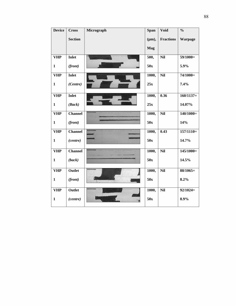
88
Device Cross
Section
Micrograph Span
(µm),
Mag
Void
Fractions
%
Warpage
VHP
1
Inlet
(front)
500,
50x
Nil 59/1000=
5.9%
VHP
1
Inlet
(Centre)
1000,
25x
Nil 74/1000=
7.4%
VHP
1
Inlet
(Back)
1000,
25x
0.36 160/1137=
14.07%
VHP
1
Channel
(front)
1000,
50x
Nil 140/1000=
14%
VHP
1
Channel
(centre)
1000,
50x
0.43 157/1110=
14.7%
VHP
1
Channel
(back)
1000,
50x
Nil 145/1000=
14.5%
VHP
1
Outlet
(front)
1000,
50x
Nil 88/1065=
8.2%
VHP
1
Outlet
(centre)
1000,
50x
Nil 92/1024=
8.9%
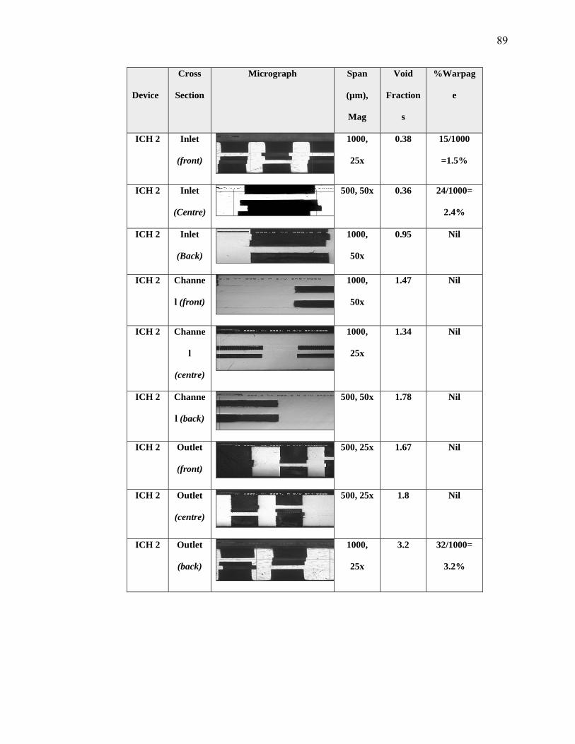
89
Device
Cross
Section
Micrograph Span
(µm),
Mag
Void
Fraction
s
%Warpag
e
ICH 2 Inlet
(front)
1000,
25x
0.38 15/1000
=1.5%
ICH 2 Inlet
(Centre)
500, 50x 0.36 24/1000=
2.4%
ICH 2 Inlet
(Back)
1000,
50x
0.95 Nil
ICH 2 Channe
l (front)
1000,
50x
1.47 Nil
ICH 2 Channe
l
(centre)
1000,
25x
1.34 Nil
ICH 2 Channe
l (back)
500, 50x 1.78 Nil
ICH 2 Outlet
(front)
500, 25x 1.67 Nil
ICH 2 Outlet
(centre)
500, 25x 1.8 Nil
ICH 2 Outlet
(back)
1000,
25x
3.2 32/1000=
3.2%

90
Device Cross
Section
Micrograph Span
(µm),
Mag
Void
Fractions
%Warpage
VHP2 Inlet
(front)
1000,
25x
Nil 79/1000=
7.9%
VHP2 Inlet
(Centre)
1000,
25x
Nil 82/1000=
8.2%
VHP2 Inlet
(Back)
1000,
25x
Nil 94/1000=
9.4%
VHP2 Channel
(front)
1000,
25x
Nil 65/1000=
6.5%
VHP2 Channel
(centre)
1000,
25x
Nil 78/1000=
7.8%
VHP2 Channel
(back)
1000,
200x
Nil 161/1000=
16.1%
VHP2 Outlet
(front)
1000,
25x
Nil 73/ 1000=
7.3%
VHP2 Outlet
(centre)
1000,
25x
Nil 81/1000=
8.1%
VHP2 Outlet
(back)
1000,
25x
Nil 89/1000=
8.9%

91
Fig C5. Unbonded regions due to bad parallelism in ICH run 1
Figure C6. Good channel geometry in first ICH device

92
Results from mean void fraction and warpage calculations for ICH sample 1 and
VHP sample 1 are shown in the tables C6, C7 and C8. The warpage in the VHP samples
is significantly greater than the warpage in ICH samples. This is due to the thermal
stresses caused by high cooling rates in the hot press.
Table C6 : Void Fraction and warpage at the inlet
Section ICH 1 VHP 1 Voids (%) Warpage (%) Voids (%) Warpage (%) Inlet (front 1) 1.84 1.5 0 5.9 Inlet (front2) 1.75 2.4 0 6.8 Inlet (middle 1) 1.86 0.19 0 7.4 Inlet (middle 2) 1.91 0.54 0 5.4 Inlet (back 1) 2.72 0 0.36 14.07 Inlet (back 2) 2.79 0 0.45 15.3 Mean 2.145 0.771666667 0.135 9.145
Table C7 : Void Fraction and warpage at the outlet
Section ICH 1 VHP 1 Voids (%) Warpage (%) Voids (%) Warpage (%) Outlet (front 1) 1.9 1.2 0 8.2 Outlet (front 2) 2.72 0.39 0 7.6 Outlet (middle 1) 2.39 1.4 0 8.9 Outlet (middle 2) 2.17 0.43 0 17.8 Outlet (back 1) 3.6 0 0.49 15.8 Outlet (back 2) 4.3 0 0.32 16.9
Mean 2.846666667 0.57 0.135 12.53333333
Table C8 : Void Fraction and warpage at the channel
Channel (front 1) 1.37 0.67 0 14 Channel (front 2) 1.45 0.72 0 14.2
Channel (middle 1) 2.19 0 0 14.7 Channel (middle 2) 2.65 1.3 0 15 Channel (back 1) 2.7 0 0 14.5 Channel (back 2) 2.9 1.5 0 13.6
Mean 2.21 0.698333333 0 14.33333333

93
Bibliography
Chapter 2 1 Kearns, W.H., 1980, Welding Handbook: Resistance and solid state welding and other joining processes, 7th Edition, volume 3, American welding society, Miami, florida, USA. 2 B. K. Paul, R. B. Peterson, "Microlamination for Microtechnology-based Energy, Chemical, and Biological Systems," ASME International Mechanical Engineering Congress and Exposition, Nashville, Tennessee, AES Volume 39, November 15-20, (1999), pp. 45-52. 3 H. Loewe, W. Ehrfeld “State-of-the-Art in Microreaction Technology: Concepts, Manufacturing and Applications”, Electrochimica Acta, (1998), vol. 44, pp. 3679-3689. 4 K. P. Kaemper, W. Ehrfeld, J. Doepper, V. Hessel, H. Lehr, H. Loewe, h.Richter, A. Wolf, “Microfluidic Components for Biological and Chemical Microreactors”, Proceedings IEEE Micro Electro Mechanical Systems, (1997), pp. 338-343. 5 Paul, B.K., P. Kwon, R. Subramanian, “Understanding limits on fin aspect ratios in counterflow microchannel arrays produced by diffusion bonding,” J. Mfg Sci. Engr., 128(4): (2006), 977-983. 6 I. Beausoleil-Morrison, “The adaptive simulation of convective heat transfer at internal building surfaces,” Building Environment 37 (2002), 791–806. 7 Peng XF, Peterson GP “The effect of thermo-fluid and geometric parameters on convection of liquid through rectangular microchannels,” Int J Heat Mass Transfer 38(4): (1995),755–758. 8 Warren M. Rohsenow, James P. Hartnett, Young I. Cho, Handbook of heat transfer, Tata Mcgraw Hill, Third Edition: Year, p.2.4-2.5, 5.67-5.72. 9 Paisarn Naphon “Laminar convective heat transfer and pressure drop in corrugated channels,” International Communications in Heat and Mass Transfer 34 (2007), 62–71. 10 B. Sunden, S. Trollheden, “Periodic laminar flow and heat transfer in a corrugated two-dimensional channel,” International Communications in Heat and Mass Transfer 16 (1989), 215–225. Chapter 3 11 U.S. Patent No. 6,129,261, 1996, “Diffusion bonding of metals” Sanders, Daniel G. 12 P. M. Martin, D. W. Matson, A. L. Tonkovich, G. L. Roberts, “Fabrication of a Stainless Steel Microchannel Microcombustor Using a Lamination Process”, Proceedings of SPIE, 1998, v. 3514, p. 386-392 13 P. M. Martin, D. W. Matson, W. D. Bennett, D. C. Steward, Y. Lin,Laser Micromachined and Laminated Microfluidic Components for Miniaturized Thermal, Chemical and Biological Systems“, Proceedings of SPIE, 1999, v. 3680, p. 826-833
94
14 R. S.Wegeng,C. J. Call, M. K. Drost, “Chemical Systems Miniaturization,” 1996 AIChE Spring Meeting, New Orleans, 1996 15 M. Martin, W. D. Bennett, and J. W. Johnson, “Microchannel Heat Exchangers for Advanced Climate Control,” Proc. SPIE (v2639, 1996), pp. 82–88 16 G. Jovanovic, J. Zaworski, T. Plant, and B. Paul, Proc. 3rd Intl. Conf. on Microreaction Technology (Frankfurt, Germany), 1999. 17 B, K. Paul, T. Dewey, D. Alman, and R. D. Wilson, “Intermetallic Microlamination for High-Temperature Reactors,” 4th Int. Conf. Microreaction Tech., Atlanta, GA, March 5–9, 2000, pp. 236–243. 18 B. K. Paul, and T. Terhaar, “Comparison of two passive microvalve designs for microlamination architectures,” J Micromech. Microengr., (v10, 2000), pp. 15–20. 19 Kuan Chenn, Second-law analysis and optimization of microchannel flows subjected to different thermal boundary conditions, International Journal of energy research 2005; 29:249–263, 13 December 2004 20 H. Loewe, W. Ehrfeld “State-of-the-Art in Microreaction Technology: Concepts, Manufacturing and Applications”, Electrochimica Acta, 1998, v. 44, p. 3679-3689 21 S. B. Dunkerton (1991), “Diffusion bonding – process and applications”, Welding and Metal Fabrication, v. 59, p. 132,134-136 22 I. Iswadi, H. Ogiyama, H. Tsukuda, “Solid State Diffusion Bonding of Superplastic Duplex Stainless Steel with Carbon Steel”, Materials Science Research International, 2003, v. 9, p. 154-159 23 Paul, B.K., P. Kwon and R. Subramanian, “Understanding Limits on Fin Aspect Ratios in Counterflow Microchannel Arrays Produced by Diffusion Bonding,” J. Mfg Sci. Engr, 128(4): 977-983, 2006. 24 Wattanutchariya, W. and B.K. Paul, “Bonding Fixture Tolerances for High-Volume Metal Microlamination Based on Fin Buckling and Laminae Misalignment Behavior,” J Intl Soc Prec Engr Nanotechology, 28(2): 117-128, 2004. 25 Paul, B., D. Palo and S. Bose, “Internal Convective Heating for Metal Microchannel Bonding,” International Conference on Micromanufacturing, Greenville, SC, 2007. 26 C. Pluess and B. Paul, “Application of Controlled Thermal Expansion in Microlamination for the Economical Production of Bulk Microchannel Systems,” Chem Engr Comm, 194(9): 2007, 1259 - 1270. 27 Wattanutchariya, W. “Application of Buckling Behavior to Evaluate and Control Shape Variation in High-Temperature Microlamination,” Ph.D. Dissertation, 2002.