an-681 pc mouse implementation using cop800 · · 2011-12-10pc mouse implementation using cop800...
TRANSCRIPT
LMC555
AN-681 PC Mouse Implementation Using COP800
Literature Number: SNAA005
TL/DD10799
PC
MO
USE
Imple
menta
tion
Usin
gC
OP800
AN
-681
National SemiconductorApplication Note 681Alvin ChanJune 1990
PCÉ MOUSEImplementation UsingCOP800
ABSTRACT
The mouse is a very convenient and popular device used in
data entry in desktop computers and workstations. For
desktop publishing, CAD, paint or drawing programs, using
the mouse is inevitable. This application note will describe
how to use the COP822C microcontroller to implement a
mouse controller.
INTRODUCTION
Mouse Systems was the first company to introduce a mouse
for PCs. Together with Microsoft and Logitech, they are the
most popular vendors in the PC mouse market. Most main-
stream PC programs that use pointing devices are able to
support the communication protocols laid down by Mouse
Systems and Microsoft.
A typical mouse consists of a microcontroller and its associ-
ated circuitry, which are a few capacitors, resistors and tran-
sistors. Accompanying the electronics are the mechanical
parts, consisting of buttons, roller ball and two disks with
slots. Together they perform several major functions: mo-
tion detection, host communication, power supply, and but-
ton status detection.
MOTION DETECTION
Motion detection with a mouse consists of four commonly
known mechanisms. They are the mechanical mouse, the
opto-mechanical mouse, the optical mouse and the wheel
mouse.
The optical mouse differs from the rest as it requires no
mechanical parts. It uses a special pad with a reflective sur-
face and grid lines. Light emitted from the LEDs at the bot-
tom of the mouse is reflected by the surface and movement
is detected with photo-transistors.
The mechanical and the opto-mechanical mouse use a roll-
er ball. The ball presses against two rollers which are con-
nected to two disks for the encoding of horizontal and verti-
cal motion. The mechanical mouse has contact points on
the disks. As the disks move they touch the contact bars,
which in turn generates signals to the microcontroller. The
opto-mechanical mouse uses disks that contain evenly
spaced slots. Each disk has a pair of LEDs on one side and
a pair of photo-transistors on the other side.
The wheel mouse has the same operation as the mechani-
cal mouse except that the ball is eliminated and the rollers
are rotated against the outside surface on which the mouse
is placed.
HOST COMMUNICATION
Besides having different operating mechanisms, the mouse
also has different modes of communication with the host. It
can be done through the system bus, the serial port or a
special connector. The bus mouse takes up an expansion
slot in the PC. The serial mouse uses one of the COM ports.
Although the rest of this report will be based on the opto-
mechanical mouse using the serial port connection, the
same principle applies to the mechanical and the wheel
mouse.
MOTION DETECTION FOR THE OPTO-MECHANICAL
MOUSE
The mechanical parts of the opto-mechanical mouse actual-
ly consist of one roller ball, two rollers connected to the
disks and two pieces of plastic with two slots on each one
for LED light to pass through. The two slots are cut so that
they form a 90 degree phase difference. The LEDs and the
photo-transistors are separated by the disks and the plastic.
As the disks move, light pulses are received by the photo-
transistors. The microcontroller can then use these quadra-
ture signals to decode the movement of the mouse.
Figure 1a shows the arrangement of the LEDs, disks, plastic
and photo-transistors. The shaft connecting the disk and
the ball is shown separately on Figure 1b. Figure 2 shows
the signals obtained from the photo-transistors when the
mouse moves. The signals will not be exactly square waves
because of unstable hand movements.
PCÉ is a registered trademark of International Business Machines Corporation.
C1995 National Semiconductor Corporation RRD-B30M75/Printed in U. S. A.

TL/DD/10799–1
a
TL/DD/10799–2
b
FIGURE 1
TL/DD/10799–3
TL/DD/10799–4
Signals at phototransistors are similar for vertical and horizontal motion.
Track 1 leads track 0 by 90 degrees
FIGURE 2
2
RESOLUTION, TRACKING SPEED
AND BAUD RATE
The resolution of the mouse is defined as the number of
movement counts the mouse can provide for each fixed dis-
tance travelled. It is dependent on the physical dimension of
the ball and the rollers. It can be calculated by measuring
the sizes of the mechanical parts.
An example for the calculation can be shown by making the
following assumptions:
# The disks have 40 slots and 40 spokes
# Each spoke has two data counts
(This will be explained in the section ‘‘An Algorithm for
Detecting Movements’’)
# Each slot also has two data counts
# The roller has a diameter of 5mm
For each revolution of the roller, there will be 40 c 2 c 2 e
160 counts of data movement. At the same time, the mouse
would have travelled a distance of q c 5 e 15.7mm.
Therefore the resolution of the mouse is 15.7/160 e
0.098mm per count. This is equivalent to 259 counts or dots
per inch (dpi).
The tracking speed is defined as the fastest speed that the
mouse can move without the microcontroller losing track of
the movement. This depends on how fast the microcontrol-
ler can sample the pulses from the photo-transistors. The
effect of a slow tracking speed will contribute to jerking
movements of the cursor on the screen.
The baud rate is fixed by the software and the protocol of
the mouse type that is being emulated. For mouse systems
and microsoft mouse, they are both 1200. Baud rate will
affect both the resolution and the tracking speed. The inter-
nal movement counter may overflow while the mouse is still
sending the last report with a slow baud rate. With a fast
baud rate, more reports can be sent for a certain distance
moved and the cursor should appear to be smoother.
POWER SUPPLY FOR THE SERIAL MOUSE
Since the serial port of the PC has no power supply lines,
the RTS, CTS, DTR and DSR RS232 interface lines are
utilized. Therefore the microcontroller and the mouse hard-
ware should have very little power consumption. National
Semiconductor’s COP822C fits into this category perfectly.
The voltage level in the RS232 lines can be either positive
or negative. When they are positive, the power supply can
be obtained by clamping down with diodes. When they are
negative, a 555 timer is used as an oscillator to transform
the voltage level to positive. The 1988 National Semicon-
ductor Linear 3 Databook has an example of how to gener-
ate a variable duty cycle oscillator using the LMC555 in
page 5-282.
While the RTS and DTR lines are used to provide the volt-
age for the mouse hardware, the TXD line of the host is
utilized as the source for the communication signals. When
idle, the TXD line is in the mark state, which is the most
negative voltage. A pnp transistor can be used to drive the
voltage of the RXD pin to a voltage level that is compatible
with the RS232 interface standard.
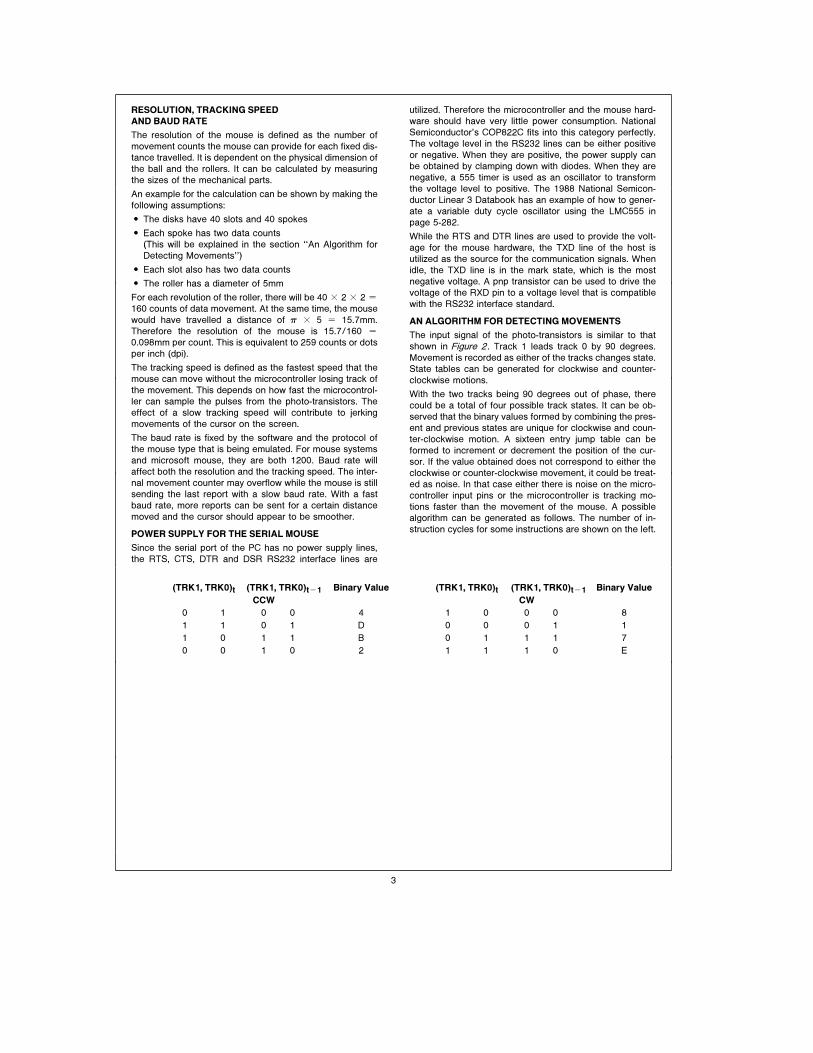
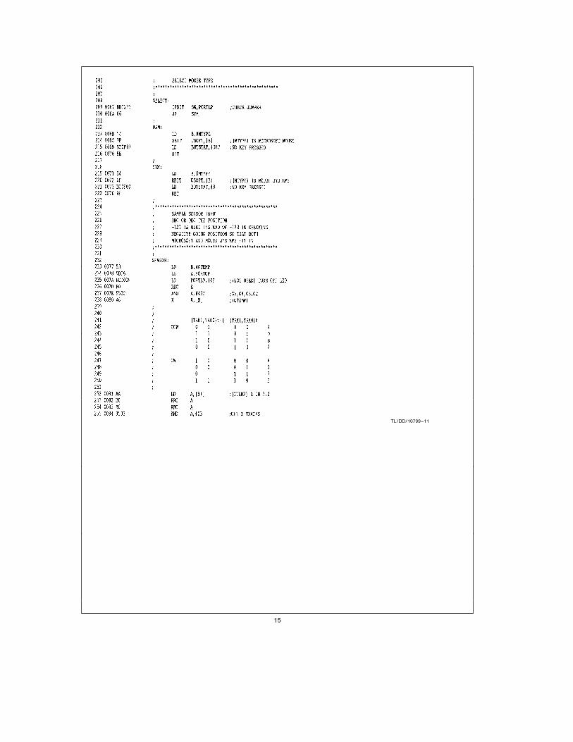
AN ALGORITHM FOR DETECTING MOVEMENTS
The input signal of the photo-transistors is similar to that
shown in Figure 2. Track 1 leads track 0 by 90 degrees.
Movement is recorded as either of the tracks changes state.
State tables can be generated for clockwise and counter-
clockwise motions.
With the two tracks being 90 degrees out of phase, there
could be a total of four possible track states. It can be ob-
served that the binary values formed by combining the pres-
ent and previous states are unique for clockwise and coun-
ter-clockwise motion. A sixteen entry jump table can be
formed to increment or decrement the position of the cur-
sor. If the value obtained does not correspond to either the
clockwise or counter-clockwise movement, it could be treat-
ed as noise. In that case either there is noise on the micro-
controller input pins or the microcontroller is tracking mo-
tions faster than the movement of the mouse. A possible
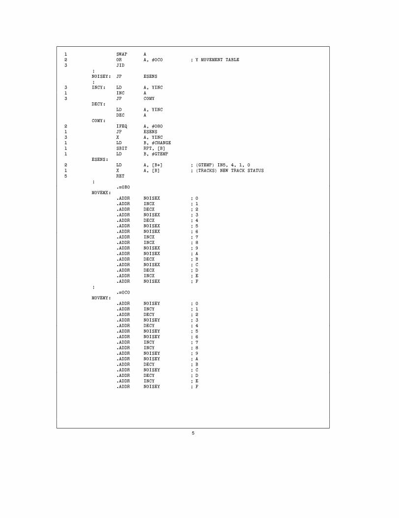
algorithm can be generated as follows. The number of in-
struction cycles for some instructions are shown on the left.
(TRK1, TRK0)t (TRK1, TRK0)tb1 Binary Value (TRK1, TRK0)t (TRK1, TRK0)tb1 Binary Value
CCW CW
0 1 0 0 4 1 0 0 0 8
1 1 0 1 D 0 0 0 1 1
1 0 1 1 B 0 1 1 1 7
0 0 1 0 2 1 1 1 0 E
3

CYCLES ;***************************************************
; SAMPLE SENSOR INPUT
; INC OR DEC THE POSITION
;***************************************************
;
SENSOR:
1 LD B,#GTEMP
3 LD A,PORTGP
1 RRC A
2 AND A,#03C ; G6,G5,G4,G3
1 X A, [B] ; (GTEMP)
;
2 LD A, [B0] ; (GTEMP) X IN 3,2
1 RRC A
1 RRC A
2 AND A, #03
1 OR A, [B] ; (TRACKS)
2 OR A, #0B0 ; X MOVEMENT TABLE
3 JID
;
NOISEX: JP YDIR
;
3 INCX: LD A,XINC
1 INC A
3 JP COMX
;
DECX: LD A,XINC
DEC A
COMX:
2 IFEQ A, #080
1 JP YDIR
3 X A, XINC
1 LD B, #CHANGE
1 SBIT RPT, [B]1 LD B, #TRACKS
;
YDIR:
2 LD A, [B1] ; (TRACKS) Y IN 5, 4
1 SWAP A
1 RRC A
1 RRC A
1 RRC A
2 AND A, #0C0
1 OR A, [B] ; (GTEMP)
4
1 SWAP A
2 OR A, #0C0 ; Y MOVEMENT TABLE
3 JID
;
NOISEY: JP ESENS
;
3 INCY: LD A, YINC
1 INC A
3 JP COMY
DECY:
LD A, YINC
DEC A
COMY:
2 IFEQ A, #080
1 JP ESENS
3 X A, YINC
1 LD B, #CHANGE
1 SBIT RPT, [B]1 LD B, #GTEMP
ESENS:
2 LD A, [B0] ; (GTEMP) IN5, 4, 1, 0
1 X A, [B] ; (TRACKS) NEW TRACK STATUS
5 RET
;
.40B0
MOVEMX:
.ADDR NOISEX ; 0
.ADDR INCX ; 1
.ADDR DECX ; 2
.ADDR NOISEX ; 3
.ADDR DECX ; 4
.ADDR NOISEX ; 5
.ADDR NOISEX ; 6
.ADDR INCX ; 7
.ADDR INCX ; 8
.ADDR NOISEX ; 9
.ADDR NOISEX ; A
.ADDR DECX ; B
.ADDR NOISEX ; C
.ADDR DECX ; D
.ADDR INCX ; E
.ADDR NOISEX ; F
;
.40C0
MOVEMY:
.ADDR NOISEY ; 0
.ADDR INCY ; 1
.ADDR DECY ; 2
.ADDR NOISEY ; 3
.ADDR DECY ; 4
.ADDR NOISEY ; 5
.ADDR NOISEY ; 6
.ADDR INCY ; 7
.ADDR INCY ; 8
.ADDR NOISEY ; 9
.ADDR NOISEY ; A
.ADDR DECY ; B
.ADDR NOISEY ; C
.ADDR DECY ; D
.ADDR INCY ; E
.ADDR NOISEY ; F
5

Going through the longest route in the sensor routine takes
75 instruction cycles. So at 5 MHz the microcontroller can
track movement changes within 150 ms by using this algo-
rithm.
MOUSE PROTOCOLS
Since most programs in the PC support the mouse systems
and microsoft mouse, these two protocols will be discussed
here. The protocols are byte-oriented and each byte is
framed by one start-bit and two stop-bits. The most com-
monly used reporting mode is that a report will be sent if
there is any change in the status of the position or of the
buttons.
MICROSOFT COMPATIBLE DATA FORMAT
Bit
6 5 4 3 2 1 0 Number
1 L R Y7 Y6 X7 X6 Byte 1
0 X5 X4 X3 X2 X1 X0 Byte 2
0 Y5 Y4 Y3 Y2 Y1 Y0 Byte 3
L, R e Key data (Left, Right key) 1 e key depressed
X0–X7 e X distance 8-bit two’s complement value b128 to a127
Y0–Y7 e Y distance 8-bit two’s complement value b128 to a127
Positive e South
In the Microsoft Compatible Format, data is transferred in
the form of seven-bit bytes. Y movement is positive to the
south and negative to the north.
FIVE BYTE PACKED BINARY FORMAT
(MOUSE SYSTEMS CORP)
Bit
7 6 5 4 3 2 1 0 Number
1 0 0 0 0 L* M* R* Byte 1
X7 X6 X5 X4 X3 X2 X1 X0 Byte 2
Y7 Y6 Y5 Y4 Y3 Y2 Y1 Y0 Byte 3
X7 X6 X5 X4 X3 X2 X1 X0 Byte 4
Y7 Y6 Y5 Y4 Y3 Y2 Y1 Y0 Byte 5
L*, M*, R* e Key data (Left, Middle, Right key), 0 e key depressed
X0–X7 e X distance 8-bit two’s complement value b127 to a127
Y0–Y7 e Y distance 8-bit two’s complement value b127 to a127
In the Five Byte Packed Binary Format data is transferred in
the form of eight-bit bytes (eight data bits without parity).
Bytes 4 and 5 are the movement of the mouse during the
transmission of the first report.
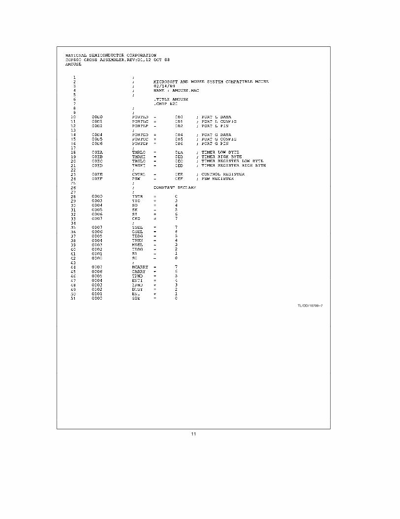
THE COP822C MICROCONTROLLER
The COP822C is an 8-bit microcontroller with 20 pins, of
which 16 are I/O pins. The I/O pins are separated into two
ports, port L and port G. Port G has built-in Schmitt-trig-
gered inputs. There is 1k of ROM and 64 bytes of RAM. In
the mouse application, the COP822C’s features used can
be summarized below. Port G is used for the photo-transis-
tor’s input. Pin G0 is used as the external interrupt input to
monitor the RTS signal for the microsoft compatible proto-
col. The internal timer can be used for baud rate timing and
interrupt generation. The COP822C draws only 4 mA at a
crystal frequency of 5 MHz. The instruction cycle time when
operating at this frequency is 2 ms.
A MOUSE EXAMPLE
The I/O pins for the COP822C are assigned as follows:
Pin Function
G0 Interrupt Input (Monitoring RTS Toggle)
G1 Reserved for Input Data (TXD of Host)
G2 Output Data (RXD of Host)
G3–G6 LED Sensor Input
L0–L2 Button Input
L3 Jumper Input (for Default Mouse Mode)
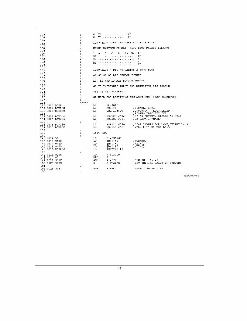
The timer is assigned for baud rate generation. It is config-
ured in the PWM auto-reload mode (with no G3 toggle out-
put) with a value of 1A0 hex in both the timer and the auto-
reload register. When operating at 5 MHz, it is equivalent to
833 ms or 1200 baud. When the timer counts down, an inter-
rupt is generated and the service routine will indicate in a
timer status byte that it is time for the next bit. The subrou-
tine that handles the transmission will look at this status
byte to send the data.
The other interrupt comes from the G0 pin. This is imple-
mented to satisfy the microsoft mouse requirement. As the
RTS line toggles, it causes the microcontroller to be inter-
rupted. The response to the toggling is the transmission of
the character ‘‘M’’ to indicate the presence of the mouse.
The main program starts by doing some initializations. Then
it loops through four subroutines that send the report, sense
the movement, sense the buttons, and set up the report
format.
Subroutine ‘‘SDATA’’ uses a state table to determine what
is to be transmitted. There are 11 or 12 states because
microsoft has only 7 data bits and mouse systems has 8.
The state table is shown below:
SENDST State
0 IDLE
1 START BIT
2–8 DATA (FOR MICROSOFT)
2–9 DATA (FOR MOUSE SYSTEMS)
9–10 STOP BIT (FOR MICROSOFT)
10–11 STOP BIT (FOR MOUSE SYSTEMS)
11 NEXT WORD (FOR MICROSOFT)
12 NEXT WORD (FOR MOUSE SYSTEMS)
The G2 pin is set to the level according to the state and the
data bit that is transmitted.
Subroutine ‘‘SENSOR’’ checks the input pins connected to
the LEDs. The horizontal direction is checked first followed
by the vertical direction. Two jump tables are needed to
decode the binary value formed by combining the present
and previous status of the wheels. The movements are re-
corded in two counters.
Subroutines ‘‘BUTUS’’ and ‘‘BUTMS’’ are used for polling
the button input. They compare the button input with the
value polled last time and set up a flag if the value changes.
Two subroutines are used for the ease of setting up reports
for different mice. The same applies for subroutines
‘‘SRPTMS’’ and ‘‘SRPTUS’’ which set up the report format
for transmission. The status change flag is checked and the
report is formatted according to the mouse protocol. The
6
movement counters are then cleared. Since the sign of the
vertical movement of mouse systems and microsoft is re-
versed, the counter value in subroutine ‘‘SRPTMS’’ is com-
plemented to form the right value.
There is an extra subroutine ‘‘SY2RPT’’ which sets up the
last two bytes in the mouse systems’ report. It is called after
the first three bytes of the report are sent.
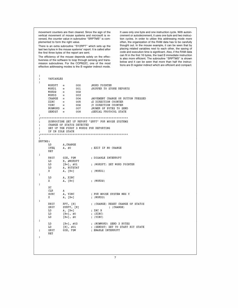
The efficiency of the mouse depends solely on the effec-
tiveness of the software to loop through sensing and trans-
mission subroutines. For the COP822C, one of the most
effective addressing modes is the B register indirect mode.
It uses only one byte and one instruction cycle. With autoin-
crement or autodecrement, it uses one byte and two instruc-
tion cycles. In order to utilize this addressing mode more
often, the organization of the RAM data has to be carefully
thought out. In the mouse example, it can be seen that by
placing related variables next to each other, the saving of
code and execution time is significant. Also, if the RAM data
can fit in the first 16 bytes, the load B immediate instruction
is also more efficient. The subroutine ‘‘SRPTMS’’ is shown
below and it can be seen that more than half the instruc-
tions are B register indirect which are efficient and compact.
;
; VARIABLES
;
WORDPT 4 000 ;WORD POINTER
WORD1 4 001 ;BUFFER TO STORE REPORTS
WORD2 4 002
WORD3 4 003
CHANGE 4 004 ;MOVEMENT CHANGE OR BUTTON PRESSED
XINC 4 005 ;X DIRECTION COUNTER
YINC 4 006 ;Y DIRECTION COUNTER
NUMWORD 4 007 ;NUMER OF BYTES TO SEND
SENDST 4 008 ;SERIAL PROTOCOL STATE
;
;******************************************************
; SUBROUTINE SET UP REPORT ’SRPT’ FOR MOUSE SYSTEMS
; CHANGE OF STATUS DETECTED
; SET UP THE FIRST 3 WORDS FOR REPORTING
; IF IN IDLE STATE
;******************************************************
;
SRPTMS:
LD A,CHANGE
IFEQ A, #0 ; EXIT IF NO CHANGE
RET
;
RBIT GIE, PSW ; DISABLE INTERRUPT
LD B, #WORDPT
LD [B0], #01 ; (WORDPT) SET WORD POINTER
LD A, BUTSTAT
X A, [B0] ; (WORD1)
;
LD A, XINC
X A, [B0] ; (WORD2)
;
SC
CLR A
SUBC A, YINC ; FOR MOUSE SYSTEM NEG Y
X A, [B0] ; (WORD3)
;
RBIT RPT, [B] ; (CHANGE) RESET CHANGE OF STATUS
SBIT SYRPT, [B] ; (CHANGE)
LD A, [B0] ; INC B
LD [B0], #0 ; (XINC)
LD [B0], #0 ; (YINC)
;
LD [B0], #03 ; (NUMWORD) SEND 3 BYTES
LD [B], #01 ; (SENDST) SET TO START BIT STATE
; SBIT GIE, PSW ; ENABLE INTERRUPT
RET
;
7

CONCLUSION
The COP822C has been used as a mouse controller. The
code presented is a minimum requirement for implementing
a mouse systems and microsoft compatible mouse. About
550 bytes of ROM code has been used. The remaining
ROM area can be used for internal diagnostics and for com-
municating with the host’s mouse driver program. The un-
used I/O pins can be used to turn the LED’s on only when
necessary to save extra power. This report demonstrated
the use of the efficient instruction set of the COP800 family.
It can be seen that the architecture of the COP822C is most
suitable for implementing a mouse controller. The table be-
low summarizes the advantages of the COP822C.
Feature Advantage
Port G Schmitt Triggered Input for Photo-Transistors
G0 External Interrupt for RTS Toggling
Timer For Baud Rate Generation
Low Power 4 mA at 5 MHz
Small Size 20-Pin DIP
REFERENCE
The mouse still reigns over data entryÐElectronic Engineer-
ing Times, October 1988.
MICE for mainstream applicationsÐPC Magazine, August
1987.
Logimouse C7 Technical Reference ManualÐLogitech,
January 1986.
APPENDIX AÐMEMORY UTILIZATION
RAM Variables
TEMP e 0F1 Work Space
ASAVE e 0F4 Save A Register
PSSAVE e 0F6 Save PSW Register
WORDPT e 000 Word Pointer
WORD1 e 001 Buffer to Store Report
WORD2 e 002 Buffer
WORD3 e 003 Buffer
CHANGE e 004 Movement or Button Change
XINC e 005 X Direction Counter
YINC e 006 Y Direction Counter
NUMWORD e 007 Number of Bytes to Send
SENDST e 008 Serial Protocol State
TSTATUS e 00A Counter Status
MTYPE e 00B Mouse Type
GTEMP e 00C Track Input from G Port
TRACKS e 00D Previous Track Status
BTEMP e 00E Button Input from L Port
BUTSTAT e 00F Previous Button Status
APPENDIX BÐSUBROUTINE SUMMARY
Subroutine Location Function
MLOOP 03D Main Program Loop
SENSOR 077 Sample Photo-Transistor Input
INTRP 0FF Interrupt Service Routines
SRPTUS 136 Set Up Report for Microsoft
SRPTMS 16C Set Up 1st 3 Bytes Report for Mouse Systems
SDATA 191 Drive Data Transmission Pin According to Bit
Value of Report
SY2RPT 1D1 Set Up Last 2 Bytes Report for Mouse Systems
BUTUS 200 Sample Button Input for Microsoft
BUTMS 210 Sample Button Input for Mouse Systems
8

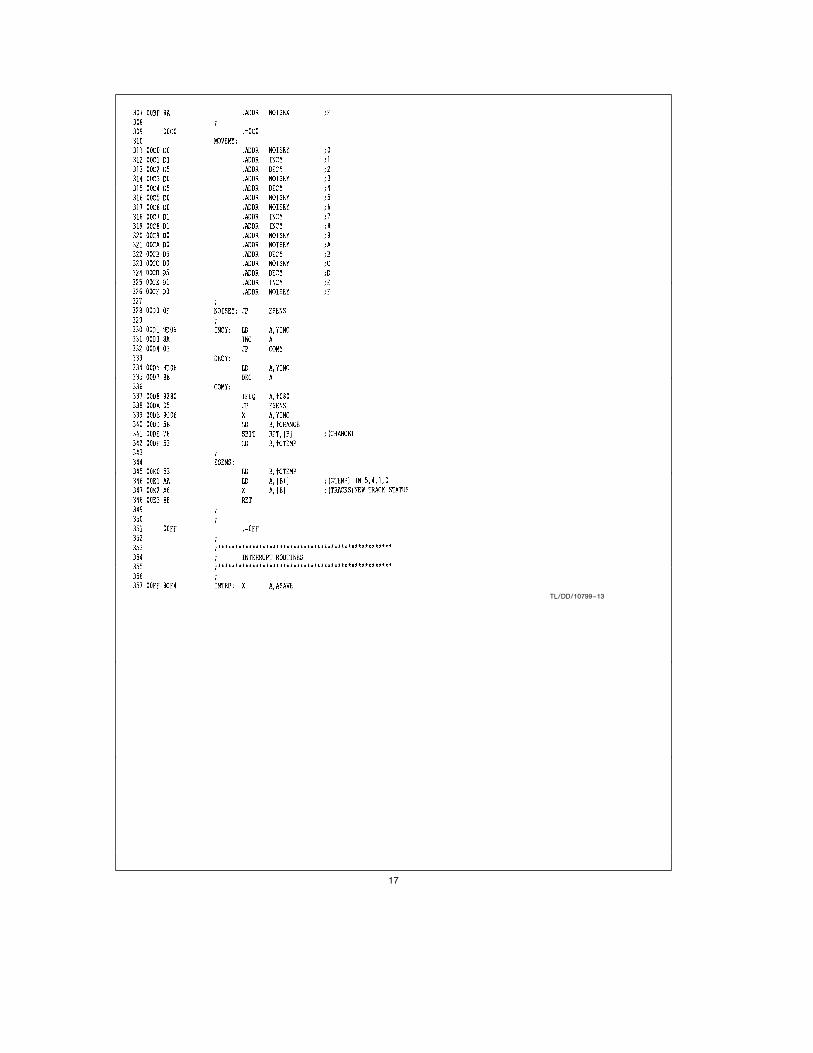
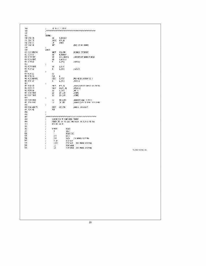
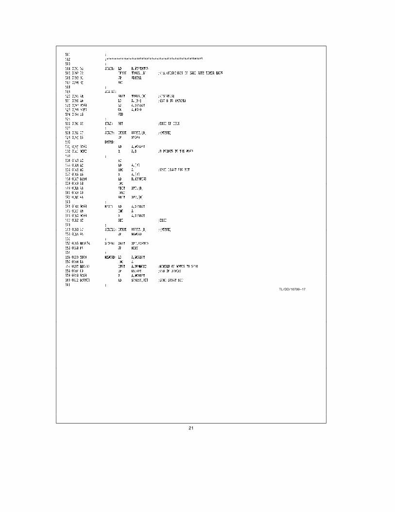
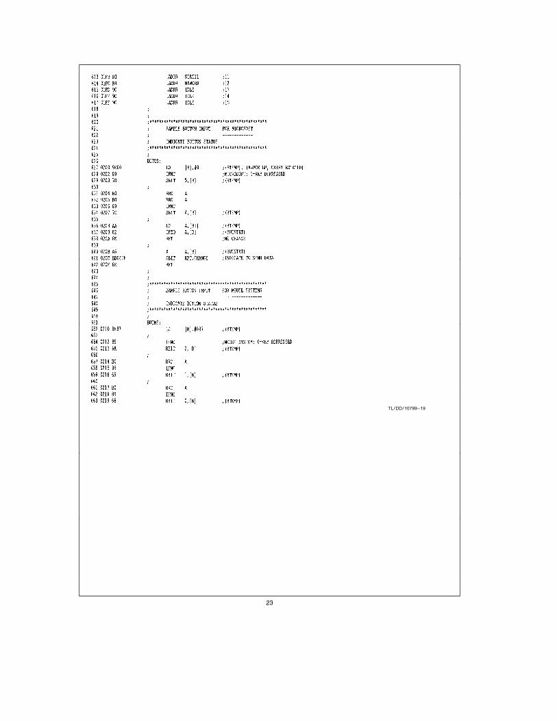
APPENDIX CÐSYSTEM SCHEMATIC, SYSTEM
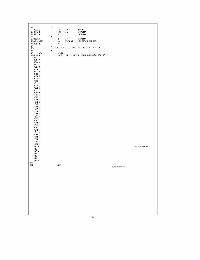
Flowchart, complete program listing.
TL/DD/10799–5
Note 1: All diodes are 1N4148.
Note 2: All resistor values are in ohms, 5%, (/8W.
Note: Unless otherwised specified
FIGURE 3. System Schematic
9

Flowchart for Mouse Systems and Microsoft Mouse
TL/DD/10799–6
10
TL/DD/10799–7
11

TL/DD/10799–8
12
TL/DD/10799–9
13

TL/DD/10799–10
14
TL/DD/10799–11
15

TL/DD/10799–12
16
TL/DD/10799–13
17

TL/DD/10799–14
18

TL/DD/10799–15
19
TL/DD/10799–16
20
TL/DD/10799–17
21

TL/DD/10799–18
22
TL/DD/10799–19
23
TL/DD/10799–20
TL/DD/10799–21
24

TL/DD/10799–22
TL/DD/10799–23
25
AN
-681
PC
MO
USE
Imple
menta
tion
Usin
gC
OP800
LIFE SUPPORT POLICY
NATIONAL’S PRODUCTS ARE NOT AUTHORIZED FOR USE AS CRITICAL COMPONENTS IN LIFE SUPPORT
DEVICES OR SYSTEMS WITHOUT THE EXPRESS WRITTEN APPROVAL OF THE PRESIDENT OF NATIONAL
SEMICONDUCTOR CORPORATION. As used herein:
1. Life support devices or systems are devices or 2. A critical component is any component of a life
systems which, (a) are intended for surgical implant support device or system whose failure to perform can
into the body, or (b) support or sustain life, and whose be reasonably expected to cause the failure of the life
failure to perform, when properly used in accordance support device or system, or to affect its safety or
with instructions for use provided in the labeling, can effectiveness.
be reasonably expected to result in a significant injury
to the user.
National Semiconductor National Semiconductor National Semiconductor National Semiconductor National Semiconductores National SemiconductorCorporation GmbH Japan Ltd. Hong Kong Ltd. Do Brazil Ltda. (Australia) Pty, Ltd.2900 Semiconductor Drive Livry-Gargan-Str. 10 Sumitomo Chemical 13th Floor, Straight Block, Rue Deputado Lacorda Franco Building 16P.O. Box 58090 D-82256 F 4urstenfeldbruck Engineering Center Ocean Centre, 5 Canton Rd. 120-3A Business Park DriveSanta Clara, CA 95052-8090 Germany Bldg. 7F Tsimshatsui, Kowloon Sao Paulo-SP Monash Business ParkTel: 1(800) 272-9959 Tel: (81-41) 35-0 1-7-1, Nakase, Mihama-Ku Hong Kong Brazil 05418-000 Nottinghill, MelbourneTWX: (910) 339-9240 Telex: 527649 Chiba-City, Tel: (852) 2737-1600 Tel: (55-11) 212-5066 Victoria 3168 Australia
Fax: (81-41) 35-1 Ciba Prefecture 261 Fax: (852) 2736-9960 Telex: 391-1131931 NSBR BR Tel: (3) 558-9999Tel: (043) 299-2300 Fax: (55-11) 212-1181 Fax: (3) 558-9998Fax: (043) 299-2500
National does not assume any responsibility for use of any circuitry described, no circuit patent licenses are implied and National reserves the right at any time without notice to change said circuitry and specifications.

IMPORTANT NOTICE
Texas Instruments Incorporated and its subsidiaries (TI) reserve the right to make corrections, modifications, enhancements, improvements,and other changes to its products and services at any time and to discontinue any product or service without notice. Customers shouldobtain the latest relevant information before placing orders and should verify that such information is current and complete. All products aresold subject to TI’s terms and conditions of sale supplied at the time of order acknowledgment.
TI warrants performance of its hardware products to the specifications applicable at the time of sale in accordance with TI’s standardwarranty. Testing and other quality control techniques are used to the extent TI deems necessary to support this warranty. Except wheremandated by government requirements, testing of all parameters of each product is not necessarily performed.
TI assumes no liability for applications assistance or customer product design. Customers are responsible for their products andapplications using TI components. To minimize the risks associated with customer products and applications, customers should provideadequate design and operating safeguards.
TI does not warrant or represent that any license, either express or implied, is granted under any TI patent right, copyright, mask work right,or other TI intellectual property right relating to any combination, machine, or process in which TI products or services are used. Informationpublished by TI regarding third-party products or services does not constitute a license from TI to use such products or services or awarranty or endorsement thereof. Use of such information may require a license from a third party under the patents or other intellectualproperty of the third party, or a license from TI under the patents or other intellectual property of TI.
Reproduction of TI information in TI data books or data sheets is permissible only if reproduction is without alteration and is accompaniedby all associated warranties, conditions, limitations, and notices. Reproduction of this information with alteration is an unfair and deceptivebusiness practice. TI is not responsible or liable for such altered documentation. Information of third parties may be subject to additionalrestrictions.
Resale of TI products or services with statements different from or beyond the parameters stated by TI for that product or service voids allexpress and any implied warranties for the associated TI product or service and is an unfair and deceptive business practice. TI is notresponsible or liable for any such statements.
TI products are not authorized for use in safety-critical applications (such as life support) where a failure of the TI product would reasonablybe expected to cause severe personal injury or death, unless officers of the parties have executed an agreement specifically governingsuch use. Buyers represent that they have all necessary expertise in the safety and regulatory ramifications of their applications, andacknowledge and agree that they are solely responsible for all legal, regulatory and safety-related requirements concerning their productsand any use of TI products in such safety-critical applications, notwithstanding any applications-related information or support that may beprovided by TI. Further, Buyers must fully indemnify TI and its representatives against any damages arising out of the use of TI products insuch safety-critical applications.
TI products are neither designed nor intended for use in military/aerospace applications or environments unless the TI products arespecifically designated by TI as military-grade or "enhanced plastic." Only products designated by TI as military-grade meet militaryspecifications. Buyers acknowledge and agree that any such use of TI products which TI has not designated as military-grade is solely atthe Buyer's risk, and that they are solely responsible for compliance with all legal and regulatory requirements in connection with such use.
TI products are neither designed nor intended for use in automotive applications or environments unless the specific TI products aredesignated by TI as compliant with ISO/TS 16949 requirements. Buyers acknowledge and agree that, if they use any non-designatedproducts in automotive applications, TI will not be responsible for any failure to meet such requirements.
Following are URLs where you can obtain information on other Texas Instruments products and application solutions:
Products Applications
Audio www.ti.com/audio Communications and Telecom www.ti.com/communications
Amplifiers amplifier.ti.com Computers and Peripherals www.ti.com/computers
Data Converters dataconverter.ti.com Consumer Electronics www.ti.com/consumer-apps
DLP® Products www.dlp.com Energy and Lighting www.ti.com/energy
DSP dsp.ti.com Industrial www.ti.com/industrial
Clocks and Timers www.ti.com/clocks Medical www.ti.com/medical
Interface interface.ti.com Security www.ti.com/security
Logic logic.ti.com Space, Avionics and Defense www.ti.com/space-avionics-defense
Power Mgmt power.ti.com Transportation and Automotive www.ti.com/automotive
Microcontrollers microcontroller.ti.com Video and Imaging www.ti.com/video
RFID www.ti-rfid.com
OMAP Mobile Processors www.ti.com/omap
Wireless Connectivity www.ti.com/wirelessconnectivity
TI E2E Community Home Page e2e.ti.com
Mailing Address: Texas Instruments, Post Office Box 655303, Dallas, Texas 75265Copyright © 2011, Texas Instruments Incorporated