an-50 ti and an-60 ti analytical rotor, cells, and ... · lxl/a-tb-003f june 2001 an-50 ti and...
TRANSCRIPT

LXL/A-TB-003FJune 2001
An-50 Ti and An-60 TiAnalytical Rotor, Cells,
and Counterbalance
For Use with the Beckman Coulter Optima
™
XL-Aand XL-I Analytical Ultracentrifuges
© 2001 Beckman Coulter, Inc.
TM

ii
SAFETY NOTICE
This safety notice summarizes information basic to the safe use of the rotor described in this manual. The international symbol displayed above is a reminder to the user that all safety instructions should be read and understood before operation or maintenance of this equipment is attempted. When you see the symbol on other pages throughout this publication, pay special attention to the specific safety informa-tion presented. Observance of safety precautions will also help to avoid actions that could damage or adversely affect the performance of the rotor. This rotor was developed, manufactured, and tested for safety and reliability as part of a Beckman Coulter centrifuge/rotor system. Its safety or reliability can-not be assured if used in a centrifuge not of Beckman Coulter’s manufacture or in a Beckman Coulter centrifuge that has been modified without Beckman Coulter’s approval.
Handle body fluids with care because they can transmit disease. No known test offers complete assurance that they are free of micro-organisms. Some of the most virulent—Hepatitis (B and C) and HIV (I–V) viruses, atypical mycobacteria, and certain systemic fungi—further emphasize the need for aerosol protection. Operator error or tube failure may generate aerosols. Do not run toxic, pathogenic, or other hazardous materials in this rotor unless you take all appropriate safety precautions. Handle all infectious samples according to good laboratory practices and methods to prevent the spread of disease. Ask your laboratory safety officer to advise you about the level of containment required for your application and about the proper decontamination or sterilization procedures to follow if fluids escape from containers. Biosafe containment should be used when Risk Group II materials (as identified in the World Health Organization
Laboratory Biosafety Manual
) are handled; materials of a higher group require more than one level of protection. Because spills may generate aerosols, observe proper safety precautions for aerosol containment.
The rotor and accessories are not designed for use with materials capable of developing flammable or explosive vapors. Do not centrifuge such materials in nor handle or store them near the centrifuge.
Although rotor components and accessories made by other manufacturers may fit in thisrotor, their safety in this rotor cannot be ascertained by Beckman Coulter. Use of other manufacturers’ components or accessories in this rotor may void the rotor warranty and should be prohibited by your laboratory safety officer. Only the components and accessories listed in this publication should be used in this rotor.
Never exceed the maximum rated speed of the rotor and rotor components in use. Refer to the section on
RUN SPEEDS
.
If disassembly reveals evidence of leakage, you should assume that some fluid escaped the rotor. Apply all appropriate safety and decontamination procedures to the centrifuge and accessories.
Do not use sharp tools on the rotor that could cause scratches in the rotor surface. Corrosion begins in scratches and may open fissures in the rotor with continued use.
!
!
!
!
!
!
!

Contents
iii
Page
Specifications — An-50 Ti Rotor . . . . . . . . . . . . . . . . . . . . . . . . . . . . . .
v
Specifications — An-60 Ti Rotor . . . . . . . . . . . . . . . . . . . . . . . . . . . . .
vi
SECTION 1: DESCRIPTION
. . . . . . . . . . . . . . . . . . . . . . . . . . . . . . . . . . . . . . . . 1-1
The Rotor . . . . . . . . . . . . . . . . . . . . . . . . . . . . . . . . . . . . . . . . . . . . . . 1-1
The Cells . . . . . . . . . . . . . . . . . . . . . . . . . . . . . . . . . . . . . . . . . . . . . . 1-2
The Counterbalance . . . . . . . . . . . . . . . . . . . . . . . . . . . . . . . . . . . . . . 1-7
SECTION 2: PREPARATION AND USE
. . . . . . . . . . . . . . . . . . . . . . . . . . . . . . 2-1
Before Getting Started . . . . . . . . . . . . . . . . . . . . . . . . . . . . . . . . . . . . 2-1
Assembling Standard and Six-Channel External-Fill Cells . . . . . . . . 2-2
Assembling Cells that Use Equilibrium CenterpieceWithout External-Fill . . . . . . . . . . . . . . . . . . . . . . . . . . . . . . . . . . 2-10
Preparing the Counterbalance . . . . . . . . . . . . . . . . . . . . . . . . . . . . . 2-12
Loading the Rotor . . . . . . . . . . . . . . . . . . . . . . . . . . . . . . . . . . . . . . 2-13
Preventing Cell Leakage . . . . . . . . . . . . . . . . . . . . . . . . . . . . . . . . . 2-15
Loading the Rotor into the Centrifuge . . . . . . . . . . . . . . . . . . . . . . . 2-16
Selecting a Run Speed . . . . . . . . . . . . . . . . . . . . . . . . . . . . . . . . . . . 2-16
Disassembling Cells after the Run . . . . . . . . . . . . . . . . . . . . . . . . . 2-17
SECTION 3: CARE AND MAINTENANCE
. . . . . . . . . . . . . . . . . . . . . . . . . . . . 3-1
Maintenance . . . . . . . . . . . . . . . . . . . . . . . . . . . . . . . . . . . . . . . . . . . . 3-1
Cleaning . . . . . . . . . . . . . . . . . . . . . . . . . . . . . . . . . . . . . . . . . . . . . . . 3-5
Decontamination . . . . . . . . . . . . . . . . . . . . . . . . . . . . . . . . . . . . . . . . 3-6
Sterilization and Disinfection . . . . . . . . . . . . . . . . . . . . . . . . . . . . . . 3-6
Returning a Rotor . . . . . . . . . . . . . . . . . . . . . . . . . . . . . . . . . . . . . . . 3-6
Supply List . . . . . . . . . . . . . . . . . . . . . . . . . . . . . . . . . . . . . . . . . . . . . 3-7
Warranty

Illustrations
iv
Table
Page
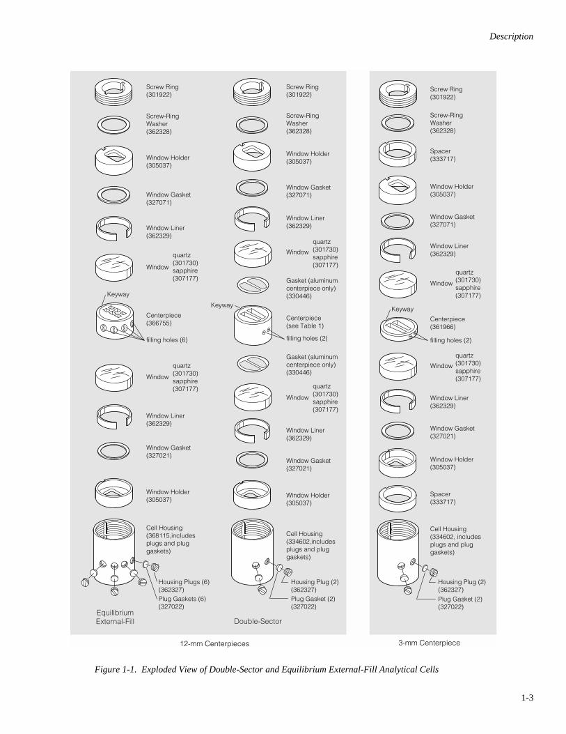
Figure 1-1. Exploded View of Double-Sector and Equilibrium External-Fill Analytical Cells . . . . . . . . . . . . . . . . . . . . . . . . . . . . . . . . . . . . . . . . . . 1-3
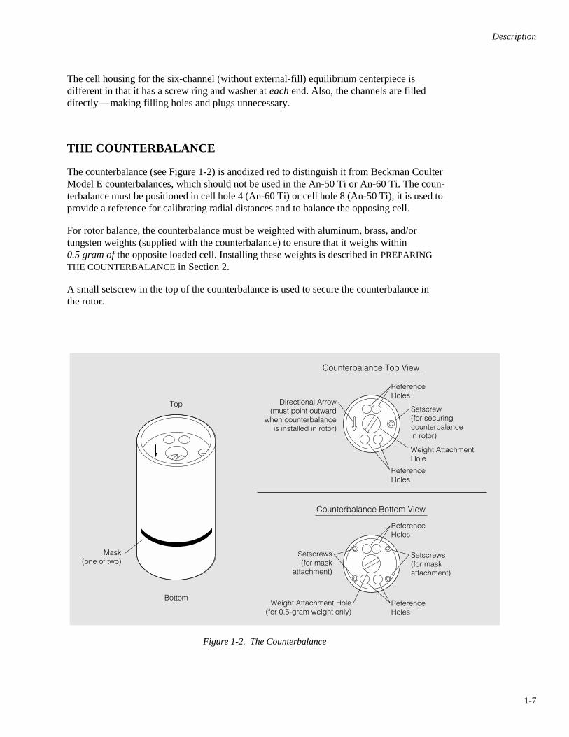
Figure 1-2. The Counterbalance . . . . . . . . . . . . . . . . . . . . . . . . . . . . . . . . . . . . . . . . . 1-7
Figure 1-3. Initiating Radial (Counterbalance) Calibration with theAbsorbance Optical System. . . . . . . . . . . . . . . . . . . . . . . . . . . . . . . . . . . 1-8
Figure 1-4. XL-A Dos Version User Interface Screen Indicating Calibrationof Cell 4 (Counterbalance). . . . . . . . . . . . . . . . . . . . . . . . . . . . . . . . . . . . 1-8
Figure 2-1. Assembling Window Components. . . . . . . . . . . . . . . . . . . . . . . . . . . . . . 2-3
Figure 2-2. Stacking 12-mm Centerpiece and Window Assemblies . . . . . . . . . . . . . 2-3
Figure 2-3. Stacking 3-mm Centerpiece, Window Assemblies, and Spacers. . . . . . . 2-4
Figure 2-4. Required Tools for Cell Assembly. . . . . . . . . . . . . . . . . . . . . . . . . . . . . . 2-5
Figure 2-5. Cell Housing, with Screw Ring and Washer . . . . . . . . . . . . . . . . . . . . . . 2-5
Figure 2-6. Filling a Standard Double-Sector or Six-Channel External-Fill Centerpiece . . . . . . . . . . . . . . . . . . . . . . . . . . . . . . . . . . . . . . . . . . . . . 2-7
Figure 2-7. Filling a Type I Band-Forming Centerpiece . . . . . . . . . . . . . . . . . . . . . . 2-8
Figure 2-8. Sealing the Filling Holes . . . . . . . . . . . . . . . . . . . . . . . . . . . . . . . . . . . . . 2-9
Figure 2-9. Assembling the Six-Channel Equilibrium Centerpiece Without External-Fill . . . . . . . . . . . . . . . . . . . . . . . . . . . . . . . . . . . . . 2-10
Figure 2-10. Reference and Sample Channels . . . . . . . . . . . . . . . . . . . . . . . . . . . . . . 2-11
Figure 2-11. Inserting Weights into the Counterbalance . . . . . . . . . . . . . . . . . . . . . . 2-12
Figure 2-12. Inserting Masks into the Counterbalance . . . . . . . . . . . . . . . . . . . . . . . 2-13
Figure 2-13. Loading the Counterbalance into the Rotor . . . . . . . . . . . . . . . . . . . . . 2-14
Figure 3-1. The Analytical Overspeed Disk and Required Tools. . . . . . . . . . . . . . . . 3-3
Figure 3-2. Correctly Aligning the Analytical Overspeed Disk on the Rotor . . . . . . 3-4
Page
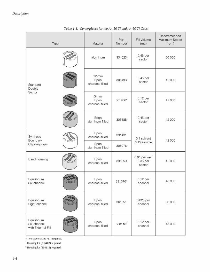
Table 1-1. Centerpieces for the An-50 Ti and An-60 Ti Cells . . . . . . . . . . . . . . . . . . 1-4

v
*
Relative Centrifugal Field (RCF) is the ratio of the centrifugal acceleration at a specified radiusand speed (
r
ω
2
) to the standard acceleration of gravity (
g
) according to the following formula:
where
r
is the radius in millimeters,
ω
is the angular velocity in radians per second(2
π
RPM /60), and
g
is the standard acceleration of gravity (9807 mm/s
2
). After substitution:
RCF rω2
g---------=
RCF 1.12 rRPM1000------------
2=
SPECIFICATIONS — An-50 Ti ROTOR
Maximum speed . . . . . . . . . . . . . . . . . . . . . . . . . . . . . . . . . . . . . 50 000 rpmNumber of rotor holes . . . . . . . . . . . . . . . . . . . . . . . . 8 (7 for sample cells;
1 for counterbalance)Relative Centrifugal Field* at maximum speed
at cell center (6.5 cm). . . . . . . . . . . . . . . . . . . . . . . . . . . . . 182 000
×
g
at
r
max
of the cell sector (cell bottom, 7.2 cm) . . . . . . . . . 201 600
×
g
Approximate acceleration time to maximum speed . . . . . . . . . . . . . . 3 minApproximate deceleration time from maximum speed
to zero . . . . . . . . . . . . . . . . . . . . . . . . . . . . . . . . . . . . . . . . . . . 3
1
/
2
minAvailable centerpieces . . . . . . . . . . . . . . . . . . . . . . . . . . . . . . . . . see Table 1Weight, fully loaded rotor . . . . . . . . . . . . . . . . . . . . . . . . . . . . . . max. 12 lbsRotor operating temperature range . . . . . . . . . . . . . . . . . . . . . . . . 0 to 40°CRotor material . . . . . . . . . . . . . . . . . . . . . . . . . . . . . . . . . . . . . . . . . . titaniumRotor classification . . . . . . . . . . . . . . . . . . . . . . . . . . . . . . . . . . . . . . . . . R, T

vi
SPECIFICATIONS — An-60 Ti ROTOR
Maximum speed. . . . . . . . . . . . . . . . . . . . . . . . . . . . . . . . . . . . . . 60 000 rpmNumber of rotor holes . . . . . . . . . . . . . . . . . . . . . . . . . 4 (3 for sample cells;
1 for counterbalance)Relative Centrifugal Field* at maximum speed
at cell center (6.5 cm) . . . . . . . . . . . . . . . . . . . . . . . . . . . . . 262 000
×
g
at
r
max
of the cell sector (cell bottom, 7.2 cm) . . . . . . . . . 290 000
×
g
Approximate acceleration time to maximum speed . . . . . . . . . . . . 3
1
/
2
minApproximate deceleration time from maximum speed
to zero . . . . . . . . . . . . . . . . . . . . . . . . . . . . . . . . . . . . . . . . . . . . 3
1
/
2
minAvailable centerpieces . . . . . . . . . . . . . . . . . . . . . . . . . . . . . . . . . see Table 1Weight, fully loaded rotor . . . . . . . . . . . . . . . . . . . . . . . . . . . . . . max. 12 lbsRotor operating temperature range . . . . . . . . . . . . . . . . . . . . . . . . 0 to 40°CRotor material . . . . . . . . . . . . . . . . . . . . . . . . . . . . . . . . . . . . . . . . . . titaniumRotor classification . . . . . . . . . . . . . . . . . . . . . . . . . . . . . . . . . . . . . . . . . R, T
*
Relative Centrifugal Field (RCF) is the ratio of the centrifugal acceleration at a specified radiusand speed (
r
ω
2
) to the standard acceleration of gravity (
g
) according to the following formula:
where
r
is the radius in millimeters,
ω
is the angular velocity in radians per second(2
π
RPM /60), and
g
is the standard acceleration of gravity (9807 mm/s
2
). After substitution:
RCF rω2
g---------=
RCF 1.12 rRPM1000------------
2=

1-1
Section 1DESCRIPTION
This section describes the An-50 Ti and An-60 Ti analytical rotors, cells, and counter-balances. Both rotors, classified R and T, are designed for use in Beckman Coulter Optima™ XL-A and Optima XL-I analytical ultracentrifuges. For complete operating instructions, XL-A customers whose systems use the Windows control software and all XL-I customers should use this manual along with the
Optima™ XL-I Analytical Ultracentrifuge Instruction Manual
(LXL/AI-IM). XL-A customers whose systems use the DOS control software should use this manual along with the
Optima™ XL-A Analytical Ultracentrifuge Instruction Manual
(LXL/A-IM) and the
Optima XL Instruction Manual
(LXL-IM).
THE ROTOR
These rotors have been manufactured in an NSAI-registered ISO 9001 or 9002 facility for use with the appropriately classified Beckman Coulter analytical ultracentrifuges.
• The An-50 Ti analytical rotor is an eight-place titanium rotor (painted black), rated for 50 000 rpm. Seven holes are for sample cells and the eighth is for the counter-balance; all are parallel to the axis of rotation.
• The An-60 Ti analytical rotor is a four-place titanium rotor (painted black), rated for 60 000 rpm. Three holes are for sample cells and the fourth is for the counter-balance; all are parallel to the axis of rotation.
In both rotors the cell holes, numbered for easy identification, together with the windows in the cells, allow light to pass through the cells for analysis of the material being centri-fuged. A handle is attached for easy lifting of the rotor.
For overspeed protection, a photoelectric detector in the XL-A/XL-I analytical ultracentri-fuge monitors the overspeed disk on the bottom of the rotor and shuts down the run if speeds exceeding the rotor’s rated maximum are detected. In addition, magnets have been inserted in the overspeed disk between cell holes 1 and 4 (An-60 Ti) or 1 and 8 (An-50 Ti). A sensor in the rotor chamber, triggered by these magnets, is used for timing the light sources. Special care should be taken to avoid damaging this dual-purpose disk; always set the rotor down carefully on the rotor stand or drive spindle. (See Section 3:
CARE AND MAINTENANCE
for instructions on replacing the overspeed disk if it comes off or gets damaged.)
For warranty information, see the Warranty at the back of this manual.
Description
1-2
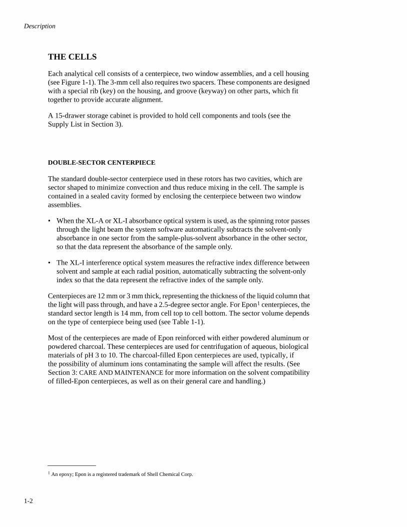
THE CELLS
Each analytical cell consists of a centerpiece, two window assemblies, and a cell housing (see Figure 1-1). The 3-mm cell also requires two spacers. These components are designed with a special rib (key) on the housing, and groove (keyway) on other parts, which fit together to provide accurate alignment.
A 15-drawer storage cabinet is provided to hold cell components and tools (see the Supply List in Section 3).
DOUBLE-SECTOR CENTERPIECE
The standard double-sector centerpiece used in these rotors has two cavities, which are sector shaped to minimize convection and thus reduce mixing in the cell. The sample is contained in a sealed cavity formed by enclosing the centerpiece between two window assemblies.
• When the XL-A or XL-I absorbance optical system is used, as the spinning rotor passes through the light beam the system software automatically subtracts the solvent-only absorbance in one sector from the sample-plus-solvent absorbance in the other sector, so that the data represent the absorbance of the sample only.
• The XL-I interference optical system measures the refractive index difference between solvent and sample at each radial position, automatically subtracting the solvent-only index so that the data represent the refractive index of the sample only.
Centerpieces are 12 mm or 3 mm thick, representing the thickness of the liquid column that the light will pass through, and have a 2.5-degree sector angle. For Epon
1
centerpieces, the standard sector length is 14 mm, from cell top to cell bottom. The sector volume depends on the type of centerpiece being used (see Table 1-1).
Most of the centerpieces are made of Epon reinforced with either powdered aluminum or powdered charcoal. These centerpieces are used for centrifugation of aqueous, biological materials of pH 3 to 10. The charcoal-filled Epon centerpieces are used, typically, if the possibility of aluminum ions contaminating the sample will affect the results. (See Section 3:
CARE AND MAINTENANCE
for more information on the solvent compatibility of filled-Epon centerpieces, as well as on their general care and handling.)
1
An epoxy; Epon is a registered trademark of Shell Chemical Corp.
Description
1-3
Figure 1-1. Exploded View of Double-Sector and Equilibrium External-Fill Analytical Cells
12-mm Centerpieces
Screw Ring(301922)
Screw Ring(301922)
Screw-RingWasher(362328)
Screw-RingWasher(362328)
Window Holder(305037)
Window Holder(305037)
Window Holder(305037)
Window Holder(305037)
Window Liner(362329)
Window Liner(362329)
Window Liner(362329)
Window Liner(362329)
Window
quartz(301730)sapphire(307177)
Window
quartz(301730)sapphire(307177)
Window
quartz(301730)sapphire(307177)
Window
quartz(301730)sapphire(307177)
Centerpiece(see Table 1)
Centerpiece(361966)
filling holes (2)
Cell Housing(334602,includesplugs and pluggaskets)
Cell Housing(334602, includesplugs and pluggaskets)
Keyway
Housing Plug (2)(362327)Plug Gasket (2)(327022)
Housing Plug (2)(362327)Plug Gasket (2)(327022)
Window Gasket(327071)
Window Gasket(327071)
Window Gasket(327021)
Window Gasket(327021)
Gasket (aluminumcenterpiece only)(330446)
Gasket (aluminumcenterpiece only)(330446)
3-mm Centerpiece
Spacer(333717)
Spacer(333717)
filling holes (2)
Screw Ring(301922)
Screw-RingWasher(362328)
Window Holder(305037)
Window Holder(305037)
Window Liner(362329)
Window Liner(362329)
Window
quartz(301730)sapphire(307177)
Window
quartz(301730)sapphire(307177)
Centerpiece(366755)
filling holes (6)
Cell Housing(368115,includesplugs and pluggaskets)
Keyway
Housing Plugs (6)(362327)Plug Gaskets (6)(327022)
Window Gasket(327071)
Window Gasket(327021)
Keyway
EquilibriumExternal-Fill Double-Sector
Description
1-4
Table 1-1. Centerpieces for the An-50 Ti and An-60 Ti Cells
* Two spacers (333717) required.
†
Housing kit (335402) required.
‡
Housing kit (368115) required.
Type MaterialPart
NumberFill Volume
(mL)
RecommendedMaximum Speed
(rpm)
StandardDoubleSector
aluminum 3346230.45 persector
60 000
12-mmEpon
charcoal-filled306493
0.45 persector
42 000
3-mmEpon
charcoal-filled361966*
0.12 persector
42 000
Eponaluminum-filled
3056850.45 persector
42 000
SyntheticBoundaryCapillary-type
Eponcharcoal-filled
3314310.4 solvent
0.15 sample42 000
Eponaluminum-filled
306076
Band Forming Eponcharcoal-filled
3313590.01 per well
0.35 persector
42 000
EquilibriumSix-channel
Eponcharcoal-filled 331376
†
0.12 perchannel
48 000
EquilibriumEight-channel
Eponcharcoal-filled
3618510.025 perchannel
50 000
EquilibriumSix-channelwith External-Fill
Eponcharcoal-filled 368116
‡
0.12 perchannel
48 000

Description
1-5
SIX-CHANNEL OR EIGHT-CHANNEL EQUILIBRIUM CENTERPIECE(WITHOUT EXTERNAL-FILL)
The six-channel equilibrium centerpiece is designed for centrifugation of three sample-solvent pairs simultaneously. Three channels hold solvent, and three channels hold sample-solvent mixture. Each channel holds a liquid column about 3 mm high or less from base to meniscus; this short column height greatly reduces the time required to reach equilibrium in sedimentation equilibrium studies.
The eight-channel equilibrium centerpiece is similar to the six-channel, except it is designed for centrifugation of four sample-solvent pairs simultaneously, enabling increased sample throughput and lower loading volumes. Four channels hold solvent, and four channels hold sample-solvent mixture. The channels are parallel and the column height is short. The eight-channel centerpiece is designed for use with interference optics—the holes are spaced in line with the slits for the laser output. (The timing of the flash lamp with absorbance optics will not give equal intensities between the parallel channels of this centerpiece.)
SYNTHETIC BOUNDARY CENTERPIECE
Synthetic boundary centerpieces are designed to layer one solution onto another solution during centrifugation. Two capillaries are scribed on the face of the synthetic boundary centerpiece, between the sectors. Solution from one sector flows into the other through the lower capillary while air flows out through the upper capillary. The quick formation of the boundary allows you to make measurements during the time that would otherwise be required for the boundary to clear the meniscus. This is particularly helpful when working with solutes that have low sedimentation rates, or with rapidly diffusing solutes that might never clear the meniscus in the usual boundary velocity run.
With the absorbance optical system, this centerpiece is used to determine the diffusion coefficient of the sample. With the interference optical system, the centerpiece is used for preliminary experiments to determine the total number of fringes that characterize the concentration of solutions to be studied. The synthetic boundary centerpiece can be used with the interference system to determine the extinction coefficient of the sample.
SIX-CHANNEL EQUILIBRIUM EXTERNAL-FILL CENTERPIECE
The six-channel external-fill centerpiece has the same sector dimensions and filling requirements as the standard six-channel centerpiece, but is designed to be loaded and unloaded without disassembling the cell. The ability to run a cell empty, with buffer, and then with solution allows the user to subtract out any window or cell artifacts. The center-piece has a filling hole to each side of the sector. Each pair of filling holes is located on the outside of the centerpiece. The cell housing has six filling holes and brass screws that align with the centerpiece filling holes. The centerpiece can be used in either orientation in the housing; however, for consistency it is best to load the centerpiece so the numbers on the centerpiece and cell housing are in the same orientation when assembled.

Description
1-6
BAND-FORMING CENTERPIECE
Band-forming centerpieces are designed to transfer sample from the sample well onto a sedimentation solvent in the sector during centrifugation. The sample flows from the sample well through the capillary scribed on the face of the centerpiece and onto the surface of the sedimentation solvent in the sector. After the sample has migrated onto the solvent, diffusion of the small molecules between the two layers generates a gradient to stabilize the sedimenting band. When sedimentation rates of components of the sample differ sufficiently, two or more bands form and sedimentation proceeds without interaction between components.
This centerpiece is used for measuring sedimentation constants from the rate of movement of the band center of the sample. If enzyme activity can be monitored by absorbance, the sedimentation of an active enzyme can also be measured by sedimentation through substrate.
HOLMIUM OXIDE CENTERPIECE
A special holmium oxide centerpiece is used to validate instrument wavelength calibration.
The maximum speed permitted for this centerpiece is 3000 rpm, run without a vacuum to prevent cracking.
This centerpiece has holmium oxide calibration glass mounted in the center in the sample side of a standard 12-mm double-sector centerpiece. The glass is held in place with epoxy cement. As with other components, it is very important to keep the glass very clean. See
CARE OF THE HOLMIUM OXIDE CENTERPIECE
in Section 3.
WINDOWS
Quartz windows and sapphire windows are available for use in the cells. Typically, quartz windows are used with the XL-A/XL-I absorbance optical system because of the wide range of light that they transmit. The sapphire windows are recommended for use with the interference optical system; they are essential for good fringe patterns at speeds above 30 000 rpm because they produce less light refraction at higher speeds. However, they block transmission of light below approximately 240 nm.
Both types of windows fit into the same cell assembly hardware, including a vinylite gasket, a Bakelite liner, and an aluminum holder. Both types of windows must be handled carefully and checked before each use. The quality of older quartz windows should be checked before use as described in
INSPECTING QUARTZ WINDOWS
in Section 3. Sapphire windows, which have an “X” etched on the edge, are harder than quartz and can be expected to have a longer life.
CELL HOUSINGS
A special screw ring and washer (see Figure 1-1) seal the cell components into the standard and six-channel external-fill cell housings. Housing plugs and associated gaskets seal the filling holes after the centerpiece is filled.
Description
1-7
The cell housing for the six-channel (without external-fill) equilibrium centerpiece is different in that it has a screw ring and washer at
each
end. Also, the channels are filled directly—making filling holes and plugs unnecessary.
THE COUNTERBALANCE
The counterbalance (see Figure 1-2) is anodized red to distinguish it from Beckman Coulter Model E counterbalances, which should not be used in the An-50 Ti or An-60 Ti. The coun-terbalance must be positioned in cell hole 4 (An-60 Ti) or cell hole 8 (An-50 Ti); it is used to provide a reference for calibrating radial distances and to balance the opposing cell.
For rotor balance, the counterbalance must be weighted with aluminum, brass, and/or tungsten weights (supplied with the counterbalance) to ensure that it weighs within
0.5 gram of
the opposite loaded cell. Installing these weights is described in
PREPARING THE COUNTERBALANCE
in Section 2.
A small setscrew in the top of the counterbalance is used to secure the counterbalance in the rotor.
Figure 1-2. The Counterbalance
ReferenceHoles
ReferenceHoles
Directional Arrow(must point outward
when counterbalanceis installed in rotor)
Weight AttachmentHole
Setscrew(for securingcounterbalancein rotor)
Setscrews(for maskattachment)
Setscrews(for mask
attachment)
Counterbalance Top View
Mask(one of two)
Top
Bottom
ReferenceHoles
ReferenceHoles
Weight Attachment Hole(for 0.5-gram weight only)
Counterbalance Bottom View

Description
1-8
COUNTERBALANCE CALIBRATION
The XL-A and XL-I systems automatically calibrate the system software based on the known position of the counterbalance. As light passes through pairs of inner and outer reference holes in the counterbalance, known radial distances in the cell and the distances between reference edges (of the reference sector) are used to calibrate the system.
➠ NOTE
Calibration should be performed at a low speed, such as 3000 rpm. If calibration is done at low speed, the software factors in rotor stretch when higher speeds
are run.
When using the absorbance optical system, you can request the Windows control software to perform a counterbalance calibration by clicking the
Options
button on the .SCN window and then checking the
Radial calibration before first scan
box (Figure 1-3). Calibration will occur as the first scan begins. If you are using an XL-A with DOS control software, you can request counterbalance calibration by selecting
Execute Scan
from the main menu (Figure 1-4). See the XL-A instruction manual (LXL/A-IM) for detailed instructions.
Calibrating the counterbalance when the interference optical system is used first requires selecting reference edges on the camera image shown on the PC monitor, and then initiating the calibration procedure via the XL-I Windows control software. These procedures are described in the XL-A and XL-I instruction manual (LXL/AI-IM).
Figure 1-3. Initiating Radial (Counterbalance) Calibration with the Absorbance Optical System
Figure 1-4. XL-A DOS Version User Interface Screen Indicating Calibration of Cell 4 (Counterbalance)
Check this boxto initiate calibrationbefore the first scan
S e t U p S c a n E x e c u t e S c a n D i s p l a y S c a n U t i l i t i e s e X i t
R e v i e w a c t i v e c e l ls T a r t s c a nS t o p s c a ns t a r t A u t o s c a ns t O p X Ls P e c i a l
S t a t u sC e l l #r a d i u sW a v e l e n g t hS p e e dE l a p s e T i m eT e m p e r a t u r e
C a l i b r a t i n g B a s e l i n e47 . 1 1 88 8 63 0 0 08 8 3 32 5
C MN MR P MS e c o n d sC e l s i u s
:::::::

2-1
Section 2PREPARATION AND USE
Keep the rotor on its stand whenever possible to avoid damaging the overspeed disk. If it is necessary to cool the rotor prior to the run, refrigerate the cells after they have been assembled.
➠ NOTE
Although rotor components and accessories madeby other manufacturers may fit in the An-50 Ti or An-60 Ti rotor, their safety in this rotor cannot be ascertained by Beckman Coulter. Use of other manufacturers’ components or accessories in this rotor may void the rotor warranty and should be prohibited by your laboratory safety officer. Only the components and accessories listed in this publication should be used in this rotor.
Analytical accessories manufactured by Beckman Coulter for use in the Model E analytical ultracentri-fuge cannot be used in the An-50 Ti or An-60 Ti rotor.
BEFORE GETTING STARTED
Use the checklist below each time you use the rotor to ensure that all components are clean and in proper working order.
• Wash and dry new components before they are used for the first time.
• Inspect all cell components and replace any that are damaged or show signs of wear.
• Check that the screw-ring threads are clean and free of burrs, and that the screw-ring washer is clean and not deformed or broken.

Preparation and Use
2-2
• Check that the window holders are not distorted, that window gaskets are clean and not damaged, and that window liners are not frayed at the edges.
• Lightly lubricate all components with aluminum surfaces (cell housing, screw ring, etc.) with Spinkote™ lubricant (306812) to prevent scratches and abrasion where these components contact each other.
• Check that the windows are not cracked or scratched in the area that will cover the sectors.
• Make sure that the windows are scrupulously clean—without fingerprints, smudges, dust, or lint. See Section 3 for detailed cleaning instructions. Once windows are clean, handle them by the edges only, using a lintless tissue.
• Be sure that the centerpiece face and the wall between the centerpiece sectors are not scratched, cracked, or irregularly shaped, and that the capillaries in synthetic boundary centerpieces are in good condition.
• Check that the cell-housing threads are clean and not nicked, that the housing keyway is not nicked, that the filling holes are clean and free of burrs, and that the housing itself is not deformed.
• When using more than one cell, use the same type of centerpieces in opposing cells to ensure that the assembled cells weigh within 0.5 gram of each other. (An imbalanced load can move the center of rotation slightly, causing an erroneous reading.)
• For optimal results, rebuild cells identically between uses so that you can easily identify repetitive noise in multiple data sets.
ASSEMBLING STANDARD AND SIX-CHANNEL EXTERNAL-FILL CELLS
STEP 1: ASSEMBLE WINDOWS (Two windows are needed per cell.)
a. Place a window gasket (see Figure 2-1) in the window holder. (Use gaskets only a few times, as they become bent or otherwise damaged with repeated use.)
b. Place a liner in the window holder, over the gasket, with the gap in the liner opposite (180 degrees) from the keyway.
c. Hold the window with a lintless tissue and carefully insert it into the holder, aligning the mark with the keyway. (It helps to drop the window in at a slight angle, starting at the keyway.) Make sure that no fingerprints or smudges get on the window.
d. Repeat instructions a through c for the second window assembly.
If you are using band-forming centerpieces, you must add sample before proceeding. Refer to Step 5 below for instructions. If you are using six-channel equilibrium centerpieces without external-fill, refer to the special instructions following Step 8.

Preparation and Use
2-3
Figure 2-1. Assembling Window Components
STEP 2: STACK THE CENTERPIECE AND WINDOW ASSEMBLIES.
a. Double check that all cell components are scrupulously clean —to prevent leakage or damage to the centerpieces.
b. With the keyways aligned, stack the components in this order: window assembly on the bottom (window up), centerpiece in the middle (capillaries facing down in synthetic boundary centerpieces), and window assembly on top (window down); see Figure 2-2 or Figure 2-3.
Figure 2-2. Stacking 12-mm Centerpiece and Window Assemblies
Window Holder
Liner
Gap oppositealigning mark
Window
Window Gasket
Keyway
Window Assembly
Window Assembly
Centerpiece
Preparation and Use
2-4
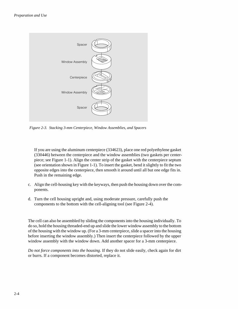
Figure 2-3. Stacking 3-mm Centerpiece, Window Assemblies, and Spacers
If you are using the aluminum centerpiece (334623), place one red polyethylene gasket (330446) between the centerpiece and the window assemblies (two gaskets per center-piece; see Figure 1-1). Align the center strip of the gasket with the centerpiece septum (see orientation shown in Figure 1-1). To insert the gasket, bend it slightly to fit the two opposite edges into the centerpiece, then smooth it around until all but one edge fits in. Push in the remaining edge.
c. Align the cell-housing key with the keyways, then push the housing down over the com-ponents.
d. Turn the cell housing upright and, using moderate pressure, carefully push the components to the bottom with the cell-aligning tool (see Figure 2-4).
The cell can also be assembled by sliding the components into the housing individually. To do so, hold the housing threaded-end up and slide the lower window assembly to the bottom of the housing with the window up. (For a 3-mm centerpiece, slide a spacer into the housing before inserting the window assembly.) Then insert the centerpiece followed by the upper window assembly with the window down. Add another spacer for a 3-mm centerpiece.
Do not force components into the housing. If they do not slide easily, check again for dirt or burrs. If a component becomes distorted, replace it.
Window Assembly
Spacer
Spacer
Centerpiece
Window Assembly

Preparation and Use
2-5
Figure 2-4. Required Tools for Cell Assembly
STEP 3: INSERT THE SCREW RING INTO THE HOUSING.
a. Apply a thin film of Spinkote lubricant to both sides of the screw-ring washer and to the threads of the screw ring (Figure 2-5) after the cell components are in place.
b. Place the lubricated washer into the housing on top of the window holder.
Figure 2-5. Cell Housing, with Screw Ring and Washer
Cell Aligning Tool(362340)
Screwdriver(807371)
Gasket Rod(302194)
Used to align cells inrotor, push componentsout of cells, and removescrew rings from housings.
Used to screwhousing plugs
into filling holes.
Used to remove orinsert cell gaskets.
Cell Housing(334602)
Screw Ring Washer(362328)
Screw Ring(301922)

Preparation and Use
2-6
c. Orient the screw ring so that the side inscribed “OUT” is facing up. Begin turning the screw ring manually, then use the flat end of the cell-aligning tool to finish screwing the ring into the housing.
➠ NOTE
The screw has a buttress thread. Forcing the ring to screw in the wrong way will strip the threads and ruin the housing.
STEP 4: TIGHTEN THE SCREW RING.
a. Place the cell housing in the cell torque collet. (Refer to How to Use the Cell Torque Wrench [E-TB-016], for detailed instructions on using this tool.)
b. If a 12-mm centerpiece is used, use the torque wrench to tighten the screw ring to about 120 inch-pounds. If a 3-mm centerpiece is used, tighten the screw ring to 135 inch-pounds to prevent leakage at higher run speeds.
c. Release the torque from the collet and remove the cell from the vise. DO NOT touch the windows.
STEP 5: FILL THE CENTERPIECES.
WARNING!Normal operation can involve the use of reagents which may be toxic or biologically harmful. Observe all cautionary information printed on the original solution containers prior to their use. Dispose of all waste solutions in a proper manner. Handle infectious samples according to good labo-ratory procedures and methods to prevent spread of disease.
a. To avoid scratching the sector surfaces, fill the centerpieces using either an adjustable pipette with gel-loading tips, or a syringe and Hamilton polyethylene tubing (Figure 2-6).

Preparation and Use
2-7
Figure 2-6. Filling a Standard Double-Sector or Six-Channel External-Fill Centerpiece
b. Fill centerpieces using the appropriate procedure.
• Standard double-sector centerpieces. Each sector holds a maximum volume of about 0.45 mL. Hold the cell horizontally with the screw-ring end toward you and the filling holes up. Fill the reference (left) sector with solvent; fill the sample (right) sector with sample-solvent mixture (see Figure 2-6). Use a greater total volume (usually 10 to 20 µL) in the reference sector so that the sample meniscus is easily recognized.
• Six-channel equilibrium external-fill centerpieces. Turn the housing right side up; hold it with the housing holes to your left. Looking into the housing, the front (reference) row of channels is for solvent only; the back (sample) row is for sample plus solvent. Load 0.10 to 0.12 mL of sample/solvent into the back row of channels, and 0.11 to 0.13 mL of solvent only into the front channels. The difference in channel volumes (approximately 0.01 mL) provides a slight separation in the menisci patterns of each pair, making distinction of the menisci easier in the final scan.
• Synthetic boundary capillary-type centerpieces. The centerpiece should be placed in the housing with the capillaries up. Load the centerpiece as described above for standard centerpieces. Fill the reference (left) sector with 0.40 mL of solvent; fill the
Solvent Sample-solvent
Screw-ring End
Syringe and tubing methodPipettemethod

Preparation and Use
2-8
sample (right) sector with about 0.15 mL of sample-solvent mixture or just to the capillary. The volume of sample in the (right) sector must be such that the meniscus (when running) is below the transfer capillary.
• Band-forming centerpieces. The sample wells must be filled before the cell is completely assembled. After inserting the first window assembly and centerpiece into the housing, hold the cell upright with the filling holes away from you. From the top, load 0.01 mL of sample into the right sample well; load 0.01 mL of buffer into the left sample well (Figure 2-7). Finish assembling the cell by adding the final window assembly, screw ring and washer, as described in Steps 2 through 4.
After the cell is torqued, hold it horizontally with the screw-ring end toward you and the filling holes up. Fill each sector with about 0.35 mL of buffer (or up to the capillary).
Figure 2-7. Filling a Type I Band-Forming Centerpiece
STEP 6: SEAL THE FILLING HOLES.
a. Place a new red polyethylene plug gasket on each filling hole (see Figure 2-8).
b. Screw the housing plugs in, using the small flat-edge screwdriver provided. Hand tighten the plugs—DO NOT tighten them too much or the housing will distort, making installa-tion into the rotor very difficult. Centrifugal force on the plugs will seal the filling holes.
Sample Well
Sector

Preparation and Use
2-9
➠ NOTE
The brass screws can be tightened to seat loose-fitting cells more snugly.
Figure 2-8. Sealing the Filling Holes
STEP 7: ASSEMBLE OTHER CELLS IF REQUIRED.
Follow Steps 1 through 6 above to assemble cells 2 and 3 (An-60 Ti) or 2 through 7 (An-50 Ti), if required.
STEP 8: WEIGH THE ASSEMBLED CELLS.
a. Weigh the assembled cells. Make sure that opposing cells weigh within 0.5 gram of each other. (If they do not, recheck that the centerpieces are alike and the volumes similar.)
b. Proceed directly to PREPARING THE COUNTERBALANCE and LOADING THE ROTOR, below. (Skip the following section on equilibrium centerpieces.) Be sure that when weighed, the counterbalance is equal to or up to 0.5 gram lighter than the opposite cell.
Housing Plugs
Red Plug Gaskets

Preparation and Use
2-10
ASSEMBLING CELLS THAT USE THE EQUILIBRIUM CENTERPIECE WITHOUT EXTERNAL-FILL
The cell housing for the six-channel or eight-channel equilibrium centerpiece is special in that it has a screw ring and washer at each end (see Figure 2-9) and does not use housing plugs or gaskets. (The holes in the housing are used as a reference point only.) The top of the housing is defined as the end that is up when the part number inscribed on the side of the housing is right side up.
Figure 2-9. Assembling the Six-Channel Equilibrium Centerpiece Without External-Fill. Eight-channel centerpiece assemblies are similar.
1. Turn the housing upside down (part number will be upside down), then slide the centerpiece into the housing as far as it will go, aligning the keyway with the housing key. Add the lower window assembly, window down, and the window liner towards the keyway.
2. Apply a thin film of Spinkote lubricant (306812) to the two screw-ring washers and to the threads of the two screw rings. Place a lubricated washer on the window assembly. Screw in the lower screw ring, using the flat end of the cell-aligning tool.
3. Torque the first screw ring to 60 inch-pounds, using the cell torque wrench.
Six-channelCenterpiece
(331376)
Note orientationof part number
Housing Top

Preparation and Use
2-11
4. Turn the housing right side up; hold it with the housing holes to your left. Looking into the housing, the front (reference) row of channels is for solvent only; the back (sample) row is for sample plus solvent (Figure 2-10).
a. Prepare a syringe with delivery tubing attached (such as Hamilton polyethylene tub-ing) or use adjustable pipettes with gel-loading disposable tips.
b. Load 0.10 to 0.12 mL of sample/solvent into the back row of channels, and 0.11 to 0.13 mL of solvent only into the front channels. The difference in channel volumes (approximately 0.01 mL) provides a slight separation in the menisci patterns of each pair, making distinction of the menisci easier in the final scan.
5. After the centerpiece is filled, slide the upper window assembly—window down and window liner towards the keyway—into the cell housing. Place a lubricated screw- ring washer on top and screw in the lubricated ring.
➠ NOTE
Be careful not to spill the centerpiece contents before the final torque (step 7).
6. Torque the second screw ring to 120 inch-pounds, using the cell torque wrench.
7. Turn the cell over and torque the lower ring to 120 inch-pounds, using the cell torque wrench.
Figure 2-10. Reference and Sample Channels. Six-channel centerpiece shown;eight-channel centerpiece channels are referenced the same as the six-channel.
Sample Channels (Top Row):Sample Plus Solvent
Reference Channels (Bottom Row):Solvent
Housing Top

Preparation and Use
2-12
8. Place the cell (with the six-digit part number right side up) into the rotor so that the three channels with the highest concentration of sample are toward the center of the rotor. If the cell fits loosely, remove it and insert plug gaskets and screws into the housing holes and tighten slightly. Return the cell to the rotor.
PREPARING THE COUNTERBALANCE
The aluminum, brass, and tungsten weights supplied in the counterbalance set are numbered in 1-gram increments (labeled on end); each set also includes a 0.5-gram aluminum weight.
1. Screw weights into the weight attachment hole at the top of the counterbalance (see Figure 2-11) so that the counterbalance weighs within 0.5 gram of the assembled cell.
2. If you need to use the 0.5-gram weight, screw it into the weight attachment hole at the bottom of the counterbalance.
Figure 2-11. Inserting Weights into the Counterbalance
! CAUTION
Do not let the weights protrude from the top or bottom of the counterbalance. They must be flush or slightly indented. Protruding weights can get sheared off during centrifugation, which will result in damage to the rotor and the ultracentrifuge.
Weight
Setscrew
Preparation and Use
2-13
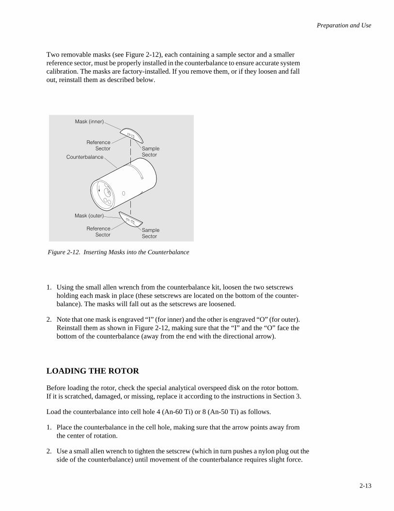
Two removable masks (see Figure 2-12), each containing a sample sector and a smaller reference sector, must be properly installed in the counterbalance to ensure accurate system calibration. The masks are factory-installed. If you remove them, or if they loosen and fall out, reinstall them as described below.
Figure 2-12. Inserting Masks into the Counterbalance
1. Using the small allen wrench from the counterbalance kit, loosen the two setscrews holding each mask in place (these setscrews are located on the bottom of the counter-balance). The masks will fall out as the setscrews are loosened.
2. Note that one mask is engraved “I” (for inner) and the other is engraved “O” (for outer). Reinstall them as shown in Figure 2-12, making sure that the “I” and the “O” face the bottom of the counterbalance (away from the end with the directional arrow).
LOADING THE ROTOR
Before loading the rotor, check the special analytical overspeed disk on the rotor bottom. If it is scratched, damaged, or missing, replace it according to the instructions in Section 3.
Load the counterbalance into cell hole 4 (An-60 Ti) or 8 (An-50 Ti) as follows.
1. Place the counterbalance in the cell hole, making sure that the arrow points away from the center of rotation.
2. Use a small allen wrench to tighten the setscrew (which in turn pushes a nylon plug out the side of the counterbalance) until movement of the counterbalance requires slight force.
Counterbalance
Mask (inner)
ReferenceSector Sample
Sector
ReferenceSector
Mask (outer)
SampleSector

Preparation and Use
2-14
3. Line the counterbalance scribe line slightly to the left (counterclockwise) of the rotor scribe mark. Then use the allen wrench to tighten the screw while twisting the counter-balance just enough to match up the two scribe lines (see Figure 2-13).
➠ NOTE
Placing a mirror under the rotor, as shown in Figure 2-13, will let you see the scribe line without having to turn the rotor on its side.
Figure 2-13. Loading the Counterbalance into the Rotor. Scribe lines are reflected in the mirror (An-60 Ti rotor shown).
Load assembled cells into cell holes 1 through 3 (An-60 Ti) or 1 through 7 (An-50 Ti) as follows.
1. Install each assembled cell with the screw-ring end up and the housing filling holes toward the center of the rotor. Match the scribe line on each cell with the scribe line in each rotor hole. Make sure that each cell assembly fits snugly enough that it does not turn in the cell hole or fall out of the rotor while you are aligning the other cells.
• An-60 Ti — One, two, or three sample cells may be run. If you are running only one sample cell, load it into cell hole 2 (opposite the counterbalance). If you are running two sample cells, place an assembled, empty cell in cell hole 2 and place the two sample cells in positions 1 and 3. Always make sure that the counterbalance weighs the same as or within 0.5 gram less than the cell in position 1, and that the sample cells in all other opposing positions weigh within 0.5 gram of each other.
Rotor Scribe Line
Counterbalance Scribe Line

Preparation and Use
2-15
• An-50 Ti — Up to seven sample cells may be run. If you are running only one sample cell, load it into cell hole 4 (opposite the counterbalance). If you are running two sample cells, place an assembled, empty cell in cell hole 4 and place the two sample cells in positions 2 and 6. If you are running more than two cells, load additional assembled cells in opposing positions. Always make sure that the counterbalance weighs the same as or within 0.5 gram less than the cell in position 4, and that the sample cells in all other opposing positions weigh within 0.5 gram of each other.
2. Refrigerate or warm the rotor and assembled cells, if required, prior to the run.
PREVENTING CELL LEAKAGE
Cell leakage can occur through the filling holes, across centerpiece faces to the outside of the cell, and from sector to sector. Massive leaks in which sample escapes the cell, such as if a window breaks, cause a temporary loss in chamber vacuum, which will be reported as a diagnostic message on the Optima XL-A/XL-I screen. Minor leaks can be identified only by the resulting movement of the menisci toward the cell bottom on the scan.
• Filling-hole leaks result from the plugs and gaskets not completely sealing the holes. This is most likely due to damage to the recess around the centerpiece filling holes. During this minor leakage, only solvent vapor is lost from the cell, so the movement of the menisci will be slow but observable. Also, convection in the cell may result from cooling of the upper layers of the cell contents as the top layer evaporates.
• Leaks across the face of the centerpiece result from scratches or dirt on the centerpiece and/or window faces, or from inadequate tightening of the cell housing. If the screw-ring threads are not lubricated, the friction may prevent adequate pressure from being applied to the window-centerpiece junction, causing the cell to leak. Keep the threads clean and lubricated. If leaks still occur, either increase the torque to 140 inch-pounds or try putting a very thin film of silicone vacuum grease on the centerpiece faces.
• Sector-to-sector leaks occur only if the fill levels of the two sectors differ by more than approximately 5 µL. Typically, sector-to-sector leakage is indicated by a single observ-able meniscus on the scan (or meniscus disappears if exactly overlaid). In almost all applications, you should use slightly less sample than reference (buffer); however, make sure that the fill levels differ by no more than 5 µL. Also keep in mind that using similar fill levels reduces the stress on the wall between the sectors and minimizes possible damage. If it is not feasible to use similar fill levels, increase the torque on the cell to about 140 inch-pounds or put a very thin film of silicone vacuum grease on the centerpiece faces.
• If leakage is due to a damaged centerpiece, replace the centerpiece.
• In the six-channel or eight-channel centerpiece, cell leakage can occur from channel to channel in the direction of centrifugal force. This leakage is identified by change in the menisci. If you detect leakage and centerpieces are clean and not distorted, try putting a very thin film of silicone vacuum grease on the centerpiece faces for the next run.

Preparation and Use
2-16
LOADING THE ROTOR INTO THE CENTRIFUGE
Carefully lower the rotor straight down onto the analytical ultracentrifuge drive shaft. Consult the Optima XL-A or XL-I instruction manual for detailed information on operating the ultracentrifuge.
SELECTING A RUN SPEED
The maximum rated speed of the An-60 Ti rotor is 60 000 rpm and maximum speed for the An-50 Ti rotor is 50 000 rpm. However, rotor speed may be limited by the type of center-piece being used (see Table 1-1). Double-sector centerpieces are not recommended for routine use at speeds greater than those listed. A sudden loss of chamber vacuum indicates major leakage; if this occurs, abort the run.
! CAUTION
Double-sector Epon centerpieces are speed rated lower than the rotor maximum because the septum between the centerpiece sectors can break or be damaged if leakage occurs while the centerpiece is running at higher speeds. With care, these center-pieces can be run up to the rotor maximum; however, Beckman Coulter is not responsible for warranty replacement of any parts broken or deformed as a result of running at speeds higher than those recom-mended in Table 1-1.
DO NOT exceed the recommended maximum speed for six-channel or eight-channel centerpieces—breakage or permanent deformation will result.

Preparation and Use
2-17
DISASSEMBLING CELLS AFTER THE RUN
WARNING!Normal operation can involve the use of reagents which may be toxic or biologically harmful. Observe all cautionary information printed on the original solution containers prior to their use. Dispose of all waste solutions in a proper manner. Handle infectious samples according to good labo-ratory procedures and methods to prevent spread of disease.
After the run, remove the cells from the rotor, using the cell-aligning tool. Then follow the instructions below to disassemble the cells.
STANDARD DOUBLE-SECTOR AND SIX-CHANNEL EXTERNAL-FILL EQUILIBRIUM CELLS
1. Unscrew and remove the housing plugs using the flat-edge screwdriver.
2. Remove the plug gaskets with the gasket rod or forceps and discard them. Be careful not to scratch the centerpiece. Withdraw the sector contents through the filling holes.
3. Loosen the screw-ring using the cell torque wrench.
4. Remove the screw-ring using the cell-aligning tool if necessary. Remove the washer.
5. Place the cell threaded-end down on a work table. Push the components out by pressing against them with your finger while lifting the housing up.
6. Push the windows out of the holders using the cell-aligning tool and thoroughly wash and dry all components (see CLEANING in Section 3 for instructions). Check the condition of the window holders. If necessary, replace parts; then reassemble.
7. Clean and dry the centerpiece, following the instructions in Section 3. Remove and discard the gaskets from aluminum centerpieces.
8. Store all cell components in a dust-free environment.

Preparation and Use
2-18
CELLS WITH SIX-CHANNEL OR EIGHT-CHANNEL EQUILIBRIUM CENTERPIECES WITHOUT EXTERNAL-FILL
1. Orient the housing with the part number facing up and loosen the top screw ring, using the torque wrench.
2. Remove the screw ring using the flat end of the cell-aligning tool, and remove the washer using the gasket rod or forceps.
3. Using forceps, carefully remove the upper window assembly from the housing. Be careful not to scratch the window. Wipe the window with a lintless tissue.
4. Place a tissue in the housing to soak up the liquid contents of the centerpiece.
5. Turn the housing over and use the torque wrench to loosen the bottom screw ring. Remove the screw ring and washer.
6. With both screw rings removed, place the housing upright on the work table. Push the tissue, centerpiece, and lower window assembly out of the housing with your finger while lifting the housing off. DO NOT push against the centerpiece itself with any tool.
7. Remove the windows from the holders using the cell-aligning tool and then clean all cell components, according to the instructions in Section 3.

3-1
Section 3CARE AND MAINTENANCE
This section describes general rotor care as well as specific procedures for the care and maintenance of the cells and counterbalance.
MAINTENANCE
• Do not use sharp tools on the rotor or components. Corrosion begins in scratches—the potential for damage from corrosion is greatest in aluminum components.
• Regularly inspect the overspeed disk. If it is scratched, damaged, or missing, replace it (see below).
• Regularly inspect and clean the rotor and cell components. Regularly lubricate cell components with aluminum surfaces (cell housing and screw ring) lightly with Spinkote lubricant (306812). Decontaminate and/or sterilize components as required.
• Regularly check the cell holes for accumulation of excess lubrication or leaked sample. If necessary, clean with a cotton swab.
• Store the rotor in a dry environment (not in the instrument).
• Store cell components and tools in the cabinet provided (see the Supply List). Special inserts have been designed for the drawers to protect the various components and tools while not in use.
Refer to Chemical Resistances (publication IN-175) for chemical resistances of rotor and rotor component materials. A list of chemicals that should not be used with filled Epon centerpieces follows later in this chapter. Your Beckman Coulter representative can provide contact with the Field Rotor Inspection Program (FRIP) and the rotor repair center.
CARE OF FILLED-EPON CENTERPIECES
Filled-Epon centerpieces are made from an epoxy resin, with either a powdered aluminum or carbon filler. The aluminum filler increases the strength and thermal conductivity of the Epon. The carbon filler makes the centerpiece opaque. After machining, the aluminum-filled

Care and Maintenance
3-2
centerpieces are soaked in a 20% solution of aluminum hydroxide to remove surface aluminum. The absorption of water by filled-Epon is negligible. Some solvents, however, may penetrate the centerpiece and soften it slightly. Generally, any softening effects can be eliminated by rinsing the centerpiece with distilled water after the run. The following chem-icals are known to cause excess softening and should not be used with Epon centerpieces:
glacial acetic acid 27% or greater aqueous ammonia chloroform diethylene triamine ethylene diamine 40% aqueous formaldehyde meta-cresol N,N-dimethyl formamide greater than 10% nitric acid 85% phosphoric acid 70% sulfuric acid tetrahydrofuran
This list is not exhaustive, and use of any nonaqueous solvent with Epon centerpieces is not recommended. Refer to Chemical Resistances for more detailed information.
CARE OF THE HOLMIUM OXIDE CENTERPIECE
The holmium oxide centerpiece is made by mounting holmium oxide glass in a standard 12-mm double-sector centerpiece, using epoxy cement.
• Be sure to keep the glass very clean; however, avoid using solvents or other liquids that could soften the centerpiece material or epoxy cement.
• Do not soak the centerpiece in any liquid for prolonged periods of time. Otherwise, clean the centerpiece as you would clean other spectrophotometer cell parts.
• Dry the centerpiece with a hot air blower or under a vacuum. However, do NOT use compressed air to dry off the centerpiece as this may leave minute oil droplets on the glass.
• Do not run this centerpiece above 3000 rpm.
INSPECTING QUARTZ WINDOWS
Due to the wavelength capabilities of the Optima XL-A/XL-I absorbance optical system, it is very important that the quartz windows used have an absorbance of less than 0.1 AU in the 190 to 800 nm range. The windows shipped with the rotor assembly have been factory checked to ensure compliance with this specification. Check the absorbance of previously purchased windows as follows.
Care and Maintenance
3-3
1. Clean the window and then check to make sure that it is clear and not scratched or otherwise damaged. Older windows may be scratched or have a yellow tint, both of which will inhibit transmission. (Even microscopic scratches can affect transmission.)
2. Use a spectrophotometer to check window absorbance. First, run a background wavelength scan from 190 to 800 nm with nothing in the light path. Then place the window to be tested in the sample light path and perform several scans, each time changing the window position slightly. This will give you several measurements in the area of the window where sample will be scanned during operation of the Optima XL-A/XL-I. Note that most readings above 0.1 AU will occur at lower wavelengths (below approximately 240 nm).
REPLACING THE ANALYTICAL OVERSPEED DISK
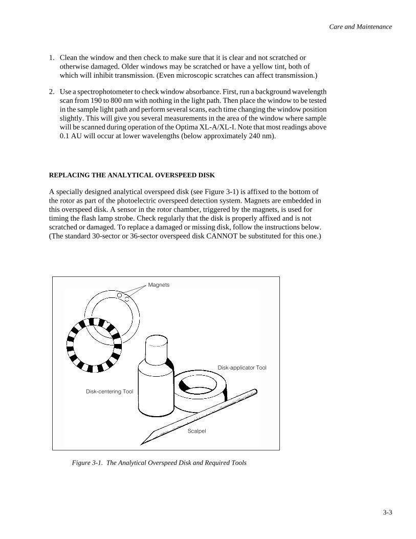
A specially designed analytical overspeed disk (see Figure 3-1) is affixed to the bottom of the rotor as part of the photoelectric overspeed detection system. Magnets are embedded in this overspeed disk. A sensor in the rotor chamber, triggered by the magnets, is used for timing the flash lamp strobe. Check regularly that the disk is properly affixed and is not scratched or damaged. To replace a damaged or missing disk, follow the instructions below. (The standard 30-sector or 36-sector overspeed disk CANNOT be substituted for this one.)
Figure 3-1. The Analytical Overspeed Disk and Required Tools
Magnets
Disk-centering Tool
Disk-applicator Tool
Scalpel

Care and Maintenance
3-4
1. Assemble these items (see Figure 3-1).
• Replacement overspeed disk (360256, An-60 Ti, or 363784, An-50 Ti)
• Disk-centering tool (331325; comes with the ultracentrifuge)
• Disk-applicator tool (360529; comes as part of the rotor starter kit)
• Scalpel (optional, not supplied; use only if old disk needs to be removed)
2. Place the rotor upside down on the lab bench. (The rotor must be dry and at room temperature because the adhesive will not stick to a damp surface.)
3. If an old disk needs to be removed, carefully pry up the edges with a scalpel and then peel off the disk. Be careful not to scratch the rotor. (If necessary, clean the area around the drive hole with acetone to remove any old adhesive.)
4. Insert the centering tool into the rotor drive hole until the lip of the tool makes contact with the rotor. (If necessary, hold the tool down to allow air to escape from the hole.)
5. Carefully peel off the backing from the new disk; make sure that all paper is removed. (It is easier to begin peeling the backing away from the magnets.) After the backing is removed, hold the disk by its edges to avoid touching the adhesive.
6. Find the aligning marks on the bottom of the rotor (see Figure 3-2). Orient the notch on the overspeed disk between the aligning marks (with adhesive facing down), then slide the disk down the centering tool until it touches the rotor. (The notch must be centered between the marks so that the magnets will be correctly placed between cell holes 1 and 4 on the An-60 Ti, or cell holes 1 and 8 on the An-50 Ti). Be sure not to bend the disk, as you may break the magnets.
Figure 3-2. Correctly Aligning the Analytical Overspeed Disk on the Rotor (An-60 Ti shown)
Disk-CenteringTool
Place notchbetween aligning marks

Care and Maintenance
3-5
7. When the disk is properly oriented, press it down using the applicator tool with about 5 lb (2 kg) of force to ensure complete adherence.
! CAUTION
Be sure to use the applicator tool. This tool affixes the overspeed disk to the rotor smoothly and completely, ensuring proper overspeed protection and detection of the magnets embedded in the disk.
8. Remove the applicator and centering tools; return them to their appropriate place in the rotor component cabinet.
9. Allow the disk to set for at least 24 hours before using the rotor.
CLEANING
Wash the rotor and rotor components immediately if salts or other corrosive materials are used or if leakage or spillage has occurred. Do not allow corrosive materials to dry on the rotor.
Under normal use, wash the rotor body frequently (at least weekly) to prevent buildup of residues.
1. Wash the rotor body in a mild detergent, such as Beckman Solution 555™, that will not damage the rotor. Scrub the cell holes with a nonabrasive brush. The Rotor Cleaning Kit (339558) contains two special plastic-coated brushes and two quarts of Solution 555 for use with rotors and accessories. Dilute the detergent 10 to 1 with water.
➠ NOTE
Do not wash the rotor and cell components in a dish-washer. Do not soak in detergent solution for long periods, such as overnight.
2. Thoroughly rinse the cleaned rotor with distilled water and allow to air dry. Do not use acetone to dry the rotor.
Cell windows and centerpieces should be cleaned after every run as described below.
• Wipe the cell windows with a lintless tissue.
• Wash the centerpieces by soaking them in warm distilled water.
• If necessary, clean the sectors with a cotton-tipped swab.

Care and Maintenance
3-6
If cell leakage has occurred, wash all components (cell housings, centerpieces, windows, window holders, window liners, screw rings, washers, and gaskets) in a mild detergent solution (Beckman Solution 555, diluted 10 to 1 with water, is recommended). Rinse cleaned components in distilled water and dry them thoroughly. To prevent corrosion, be sure that components are completely dry before they are stored.
DECONTAMINATION
If the rotor and/or cell components become contaminated with toxic or pathogenic materials, follow appropriate decontamination procedures as outlined by your laboratory safety officer. Check Chemical Resistances for acceptable solutions that will not damage the rotor or components. (Strong bases and/or high-pH solutions can damage aluminum components.)
STERILIZATION AND DISINFECTION
The rotor body can be autoclaved at 121°C for up to an hour. Of all cell components, only aluminum centerpieces can be autoclaved at 121°C. Do not autoclave Epon; use a cold sterilization method only. Ethanol1 (70%) may be used on the rotor and cell components.
While Beckman Coulter has tested these methods and found that they do not damage the rotor or components, no guarantee of sterility or disinfection is expressed or implied. When sterilization or disinfection is a concern, consult your laboratory safety officer regarding proper methods to use.
RETURNING A ROTOR
Before returning a rotor or accessory for any reason, prior permission (a Returned Goods Authorization form) must be obtained from Beckman Coulter, Inc. This RGA form may be obtained from your local Sales Office. It should contain the following information:
• serial number,
• a history of use (approximate frequency of use),
• reason for the return,
• original purchase order number, billing number, and shipping number, if possible,
• name and phone number of the person to be notified upon receipt of the rotor or acces-sory at the factory, and
• name and phone number of the person to be notified about repair costs, etc.
1 Flammability hazard. Do not use in or near operating ultracentrifuges.
Care and Maintenance
3-7
To protect our personnel, it is the customer’s responsibility to ensure that the parts are free from pathogens and/or radioactivity. Sterilization and decontamination must be done before returning the parts. Smaller items (such as tubes, bottles, etc.) should be enclosed in a sealed plastic bag.
All parts must be accompanied by a note, plainly visible on the outside of the box or bag, stating that they are safe to handle and that they are not contaminated with pathogens or radioactivity. Failure to attach this notification will result in return or disposal of the items without review of the reported problem.
Use the address label printed on the RGA form when mailing the rotor and/or components to:
Beckman Coulter, Inc. 1050 Page Mill Road Palo Alto, CA 94304 U.S.A.
Attention: Returned Goods
SUPPLY LIST
➠ NOTE
To obtain copies of referenced publications, contact Beckman Coulter, Technical Publications Depart-ment, 1050 Page Mill Road, Palo Alto, CA 94304, U.S.A. (Telephone 650-859-1753; Fax 650-859-1375).
Call Beckman Coulter Sales (1-800-742-2345 in the United States; worldwide offices are listed on the back cover of this manual) for detailed information on ordering parts and supplies. For your convenience, a partial list is given below.
REPLACEMENT ROTOR AND CELL COMPONENT PARTS
An-50 Ti rotor assembly . . . . . . . . . . . . . . . . . . . . . . . . . . . . . . . . . . . . . . . . . . . . . 363782An-60 Ti rotor assembly . . . . . . . . . . . . . . . . . . . . . . . . . . . . . . . . . . . . . . . . . . . . . 361964Analytical overspeed disk (36-sector; 50 000 rpm) . . . . . . . . . . . . . . . . . . . . . . . . . 363784Analytical overspeed disk (30-sector; 60 000 rpm) . . . . . . . . . . . . . . . . . . . . . . . . 360256Centerpieces . . . . . . . . . . . . . . . . . . . . . . . . . . . . . . . . . . . . . . . . . . . . . . . . . . . see Table 1-1Cell housing kit: double-sector with screw ring
and gasket, plugs and gaskets (does not include window assembly) . . . . . . . . 334602Cell housing kit: six-channel equilibrium, with two screw rings and gaskets
(does not include window assembly) . . . . . . . . . . . . . . . . . . . . . . . . . . . . . . . . 335402

Care and Maintenance
3-8
Cell housing kit; six-channel equilibrium external-fill, with screw ringand gaskets (does not include window assembly) . . . . . . . . . . . . . . . . . . . . . . 368115
Counterbalance and weights . . . . . . . . . . . . . . . . . . . . . . . . . . . . . . . . . . . . . . . . . . 360219Gaskets
aluminum centerpiece, red polyethylene (pkg of 10) . . . . . . . . . . . . . . . . . . . 330446housing plug, red polyethylene (pkg of 100) . . . . . . . . . . . . . . . . . . . . . . . . . . 327022window, white vinylite (pkg of 100) . . . . . . . . . . . . . . . . . . . . . . . . . . . . . . . . . 327021
Housing plugs, brass (pkg of 6) . . . . . . . . . . . . . . . . . . . . . . . . . . . . . . . . . . . . . . . . 362327Screw ring, cell housing. . . . . . . . . . . . . . . . . . . . . . . . . . . . . . . . . . . . . . . . . . . . . . 301922Spacer for 3-mm centerpiece (2 required) . . . . . . . . . . . . . . . . . . . . . . . . . . . . . . . . 333717Window assembly (quartz window, holder, gasket and liner) . . . . . . . . . . . . . . . . . 334597Window, quartz . . . . . . . . . . . . . . . . . . . . . . . . . . . . . . . . . . . . . . . . . . . . . . . . . . . . 301730Window, sapphire . . . . . . . . . . . . . . . . . . . . . . . . . . . . . . . . . . . . . . . . . . . . . . . . . . . 307177Window holder, aluminum. . . . . . . . . . . . . . . . . . . . . . . . . . . . . . . . . . . . . . . . . . . . 305037Window liner, Bakelite (pkg of 6) . . . . . . . . . . . . . . . . . . . . . . . . . . . . . . . . . . . . . . 362329Washer, screw ring, Bakelite (pkg of 6) . . . . . . . . . . . . . . . . . . . . . . . . . . . . . . . . . . 362328
TOOLS AND MISCELLANEOUS SUPPLIES
Cell-aligning tool . . . . . . . . . . . . . . . . . . . . . . . . . . . . . . . . . . . . . . . . . . . . . . . . . . 362340Gasket rod . . . . . . . . . . . . . . . . . . . . . . . . . . . . . . . . . . . . . . . . . . . . . . . . . . . . . . . . 302194Hamilton fittings and tubing . . . . . . . . . . . . . . . . . . . . . . . . . . . . . . . . . . . . . . . . . . 961332Holmium oxide calibrating centerpiece . . . . . . . . . . . . . . . . . . . . . . . . . . . . . . . . . . 362331Housing plug (flat-edge) screwdriver. . . . . . . . . . . . . . . . . . . . . . . . . . . . . . . . . . . . 807371Overspeed disk applicator tool. . . . . . . . . . . . . . . . . . . . . . . . . . . . . . . . . . . . . . . . . 360529Overspeed disk centering tool . . . . . . . . . . . . . . . . . . . . . . . . . . . . . . . . . . . . . . . . . 331325Rotor Cleaning Kit . . . . . . . . . . . . . . . . . . . . . . . . . . . . . . . . . . . . . . . . . . . . . . . . . . 339558Silicone vacuum grease (1 oz) . . . . . . . . . . . . . . . . . . . . . . . . . . . . . . . . . . . . . . . . . 335148Solution 555 (1 qt) . . . . . . . . . . . . . . . . . . . . . . . . . . . . . . . . . . . . . . . . . . . . . . . . . . 339555Spinkote lubricant (2 oz) . . . . . . . . . . . . . . . . . . . . . . . . . . . . . . . . . . . . . . . . . . . . . 306812Storage cabinet for cell components, 15-drawer . . . . . . . . . . . . . . . . . . . . . . . . . . . 961524Torque stand assembly (collet-type) . . . . . . . . . . . . . . . . . . . . . . . . . . . . . . . . . . . . 361318FC-43 oil, 1/2-ounce dropper bottle . . . . . . . . . . . . . . . . . . . . . . . . . . . . . . . . . . . . . 306394DC-550 oil, silicone, 1/2-ounce dropper bottle. . . . . . . . . . . . . . . . . . . . . . . . . . . . . 307673

ULTRACENTRIFUGE ROTOR WARRANTY
All Beckman Coulter ultracentrifuge Fixed Angle, Vertical Tube,Near Vertical Tube, Swinging Bucket, and Airfuge rotors arewarranted against defects in materials or workmanship for the timeperiods indicated below, subject to the Warranty Conditions statedbelow.
Preparative Ultracentrifuge Rotors . . . . . 5 years — No Proration
Analytical Ultracentrifuge Rotors. . . . . . 5 years — No Proration
ML and TL Series UltracentrifugeRotors . . . . . . . . . . . . . . . . . . . . . . . . . 5 years — No Proration
Airfuge Ultracentrifuge Rotors . . . . . . . . . 1 year — No Proration
For Zonal, Continuous Flow, Component Test, and Rock Coreultracentrifuge rotors, see separate warranty.
Warranty Conditions (as applicable)
1) This warranty is valid for the time periods indicated above fromthe date of shipment to the original Buyer by Beckman Coulteror an authorized Beckman Coulter representative.
2) This warranty extends only to the original Buyer and may notbe assigned or extended to a third person without writtenconsent of Beckman Coulter.
3) This warranty covers the Beckman Coulter Centrifuge Systemsonly (including but not limited to the centrifuge, rotor, andaccessories) and Beckman Coulter shall not be liable fordamage to or loss of the user’s sample, non-Beckman Coultertubes, adapters, or other rotor contents.
4) This warranty is void if the Beckman Coulter Centrifuge Sys-tem is determined by Beckman Coulter to have been operatedor maintained in a manner contrary to the instructions in theoperator’s manual(s) for the Beckman Coulter CentrifugeSystem components in use. This includes but is not limited tooperator misuse, abuse, or negligence regarding indicated main-tenance procedures, centrifuge and rotor classification require-ments, proper speed reduction for the high density of certainfluids, tubes, and tube caps, speed reduction for precipitatinggradient materials, and speed reduction for high-temperatureoperation.
5) Rotor bucket sets purchased concurrently with or subsequent tothe purchase of a Swinging Bucket Rotor are warranted only fora term co-extensive with that of the rotor for which the bucketsets are purchased.
6) This warranty does not cover the failure of a Beckman Coulterrotor in a centrifuge not of Beckman Coulter manufacture, or ifthe rotor is used in a Beckman Coulter centrifuge that has beenmodified without the written permission of Beckman Coulter,or is used with carriers, buckets, belts, or other devices not ofBeckman Coulter manufacture.
7) Rotor parts subject to wear, including but not limited to rotorO-rings, VTi, NVT™, TLV, MLN, and TLN rotor tube cavityplugs and gaskets, tubing, tools, optical overspeed disks, bear-ings, seals, and lubrication are excluded from this warranty andshould be frequently inspected and replaced if they becomeworn or damaged.
8) Keeping a rotor log is not mandatory, but may be desirable formaintenance of good laboratory practices.
Repair and Replacement Policies
1) If a Beckman Coulter rotor is determined by Beckman Coulterto be defective, Beckman Coulter will repair or replace it,subject to the Warranty Conditions. A replacement rotor will bewarranted for the time remaining on the original rotor’swarranty.
2) If a Beckman Coulter centrifuge is damaged due to a failure ofa rotor covered by this warranty, Beckman Coulter will supplyfree of charge (i) all centrifuge parts required for repair (exceptthe drive unit, which will be replaced at the then current priceless a credit determined by the total number of revolutions oryears completed, provided that such a unit was manufactured orrebuilt by Beckman Coulter), and (ii) if the centrifuge is cur-rently covered by a Beckman Coulter warranty or Full ServiceAgreement, all labor necessary for repair of the centrifuge.
3) If a Beckman Coulter rotor covered by this warranty is dam-aged due to a malfunction of a Beckman Coulter ultracentrifugecovered by an Ultracentrifuge System Service Agreement,Beckman Coulter will repair or replace the rotor free of charge.
4) If a Beckman Coulter rotor covered by this warranty isdamaged due to a failure of a Beckman Coulter tube, bottle,tube cap, spacer, or adapter, covered under the Conditions ofthis Warranty, Beckman Coulter will repair or replace the rotorand repair the instrument as per the conditions in policy point(2) above, and the replacement policy.
5) Damage to a Beckman Coulter rotor or instrument due to thefailure or malfunction of a non-Beckman Coulter tube, bottle,tube cap, spacer, or adapter is not covered under this warranty,although Beckman Coulter will assist in seeking compensationunder the manufacturer’s warranty.
Disclaimer
IT IS EXPRESSLY AGREED THAT THE ABOVE WARRANTYSHALL BE IN LIEU OF ALL WARRANTIES OF FITNESS ANDOF THE WARRANTY OF MERCHANTABILITY ANDBECKMAN COULTER, INC. SHALL HAVE NO LIABILITYFOR SPECIAL OR CONSEQUENTIAL DAMAGES OF ANYKIND WHATSOEVER ARISING OUT OF THE MANUFAC-TURE, USE, SALE, HANDLING, REPAIR, MAINTENANCE,OR REPLACEMENT OF THE PRODUCT.
Factory Rotor Inspection Service
Beckman Coulter, Inc., will provide free mechanical andmetallurgical inspection in Palo Alto, California, USA, of anyBeckman Coulter rotor at the request of the user. (Shipping chargesto Beckman Coulter are the responsibility of the user.) Rotors willbe inspected in the user’s laboratory if the centrifuge in which theyare used is covered by an appropriate Beckman Coulter ServiceAgreement. Contact your local Beckman Coulter office for detailsof service coverage or cost.
Before shipping, contact the nearest Beckman Coulter Sales andService office and request a Returned Goods Authorization (RGA)form and packaging instructions. Please include the complete rotorassembly, with buckets, lid, handle, tube cavity caps, etc. ASIGNED STATEMENT THAT THE ROTOR AND ACCESSO-RIES ARE NON-RADIOACTIVE, NON-PATHOGENIC, NON-TOXIC, AND OTHERWISE SAFE TO SHIP AND HANDLE ISREQUIRED.

Beckman Coulter Worldwide Bioresearch Division Offices
AUSTRALIABeckman Coulter Australia Pty LtdUnit D, 24 College St.Gladesville, NSW 2111AustraliaTelephone: (61) 2 9844-6000or toll free: 1 800 060 880Fax: (61) 2 9844-6096email: [email protected]
CANADABeckman Coulter (Canada) Inc.6755 Mississauga Road, Suite 600Mississauga, OntarioCanada L5N 7Y2Telephone: (905) 819-1234Fax: (905) 819-1485
CHINABeckman Coulter Inc.Beijing Representative OfficeUnit 2005A, 2006-2009, East Ocean CenterJian Guomenwai AvenueBeijing 100004China Telephone: (86) 10 6515 6028Fax: (86) 10 6515 6025, 6515 6026
EASTERN EUROPE/MIDDLE EAST/AFRICABeckman Coulter International S.A.22, Rue Juste-OlivierCase Postale 301-303CH-1260 Nyon, SwitzerlandTelephone: (41) 22 994 07 07Fax: (41) 22 994 07 00
FRANCEBeckman Coulter France S.A.Paris Nord II, 33/66 rue des VanessesB.P. 50359Villepinte, France 95942 ROISSY CDG CedexTelephone: 01 49 90 90 00Fax: 01 49 90 90 10e-mail: [email protected]
GERMANYBeckman Coulter GmbHSiemensstrasse 1D-85716 Unterschleissheim-LohhofGermanyTelephone: (89) 35870-0Fax: (89) 35870-490e-mail: [email protected]
SPAINBeckman Coulter España S.A.C/ Caleruega, 8128033 Madrid, SpainTelephone: (34) 91 3836080Fax: (34) 91 3836096email: [email protected]
SWEDENBeckman Coulter ABArchimedesvaegen 7Box 111 56SE-168 11 BrommaSwedenTelephone: (0)8 564 85 900Telefax: (0)8 564 85 901
SWITZERLANDBeckman Coulter International S.A.22, Rue Juste-OlivierCase Postale 301-303CH-1260 NyonSwitzerlandTelephone: 0800 850 810Fax: 0848 850 810
TAIWANBeckman Coulter Taiwan Inc.Taiwan Branch8th Floor216 Tun Hwa South Road, Section 2Taipei 106, Taiwan Republic of ChinaTelephone: (886) 2 2378 3456Fax: (886) 2 2377 0408
TURKEYBeckman Coulter Ltd.E-5 Yanyol Faith Cad.81410 Soganlik KartalIstanbulTurkeyTelephone: 90 216 309 1900Fax: 90 216 309 0090
UNITED KINGDOMBeckman Coulter United Kingdom LtdOakley CourtKingsmead Business ParkLondon RoadHigh WycombeBucks HP11 1JUEngland, U.K.Telephone: 01494 441181Fax: 01494 447558e-mail: [email protected]
Authorized dealers in other countries.
Beckman Coulter, Inc. • 4300 N. Harbor Boulevard, Box 3100 • Fullerton, California 92834-3100Sales: 1-800-742-2345 • Service: 1-800-551-1150 • Internet: www.beckmancoulter.com • Telex: 678413 • Fax: 1-800-643-4366
©2001 Beckman Coulter, Inc.
TM
I.S. EN ISO 9001Printed on recycled paper
HONG KONGBeckman Coulter Hong Kong Ltd.12th Floor, Oxford House979 King’s RoadTaikoo Place, Hong KongTelephone: (852) 2814 7431, 2814 0481Fax: (852) 2814 1599, 2873 4511
ITALYBeckman Coulter S.p.a.Centro Direzionale LombardoPalazzo F/1, Via Roma 10820060 Cassina de’ PecchiMilano, ItalyTelephone: 02-953921Fax: 02-95392264e-mail: [email protected]
JAPANBeckman Coulter K.K.Toranomon 37 Mori Bldg.3-5-1, ToranomonMinato-ku, Tokyo 105-0001JapanTelephone: 03-5404-8395Fax: 03-5404-8436
MEXICOBeckman Coulter de MexicoCalle Adolfo Prieto 1213Colonia Del ValleMexico D.F C.P.Mexico 03100Telephone: 525 559-16-35Fax: 525 559-36-12
NETHERLANDSBeckman Coulter Nederland B.V.Nijverheidsweg 213641 RP-MijdrechtPostbus 473640 AA MijdrechtThe NetherlandsTelephone: 0297-230630Fax: 0297-288082
SINGAPOREBeckman Coulter Singapore Pte. Ltd.116 Changi RoadUnit #03-01/02Singapore 419718Telephone: (65) 339 3633Fax: (65) 336 6303
SOUTH AFRICABeckman CoulterStand 1A Fedsure ParkTonetti Street1685 Halfway HouseJohannesburgRepublic of South AfricaTelephone: (27) 11-805-2014/5Fax: (27) 11-805-4120