an 161: using the logiclock methodology in the quartus ii...
TRANSCRIPT
December 2002, ver. 3.2 Application Note 161
Using the LogicLockMethodology in the
Quartus II Design Software
TM
Introduction Available exclusively in the Altera® Quartus® II software, the LogicLockTM block-based design flow enables you to design, optimize, and lock down a design one section at a time. With the LogicLock methodology, you can independently create and implement each logic module into a hierarchical or team-based design. With this method, you can preserve the performance of each module during system integration. Additionally, you can reuse logic modules in other designs, further leveraging resources and shortening design cycles.
The Quartus II software version 2.2 supports the LogicLock block-based design flow for the following devices:
■ StratixTM and CycloneTM devices (Quartus II software version 2.1 Service Pack 1 and higher)
■ APEXTM and APEX II devices ■ ExcaliburTM devices ■ MercuryTM devices (Mercury devices only support locked and fixed
regions)
1 This application note assumes that you are familiar with the basic functionality of the Quartus II software. For more information on using the software, refer to Quartus II Help.
See the “LogicLock Module” in the Quartus II tutorial for complete instructions on using the LogicLock feature in an example design.
LogicLock Design Flow
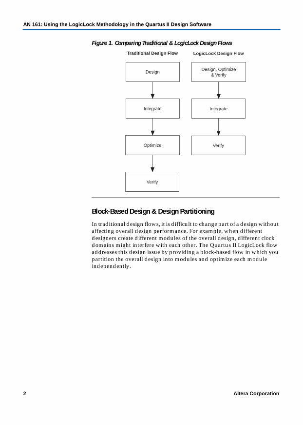
In traditional design flows, you must first design each module, integrate all of the modules into a top-level design, optimize and verify the overall design, and then verify the system. Using the LogicLock design flow, you can design and optimize each module independently, integrate all optimized modules into the top-level design, and then verify the overall system. Incorporating each module into the top-level design does not affect performance. Figure 1 compares traditional design flows with the LogicLock design flow.
Altera Corporation 1
AN-161-3.2
AN 161: Using the LogicLock Methodology in the Quartus II Design Software
Figure 1. Comparing Traditional & LogicLock Design Flows
Block-Based Design & Design Partitioning
In traditional design flows, it is difficult to change part of a design without affecting overall design performance. For example, when different designers create different modules of the overall design, different clock domains might interfere with each other. The Quartus II LogicLock flow addresses this design issue by providing a block-based flow in which you partition the overall design into modules and optimize each module independently.
Design
Integrate
Optimize
Verify
Traditional Design Flow
Design, Optimize& Verify
Integrate
Verify
LogicLock Design Flow
2 Altera Corporation

AN 161: Using the LogicLock Methodology in the Quartus II Design Software
Figure 2 shows an example design hierarchy.
Figure 2. Example Design Hierarchy
Figure 3 shows the example design partitioned into seven modules: A, B, C, D, E, F, and G. The squares around the modules indicate separate ATOM netlists. The five ATOM netlists in this case are A.vqm, B.vqm, C.vqm, D.vqm, and F.vqm. Module G is included in the module A ATOM netlist and module E is included in the module C ATOM netlist. For more information on ATOM netlists, see “Synthesize the Module” on page 20.
Figure 3. Partitioned Example Design Hierarchy
C
ED
B G
F
A
A
C
G
B
E
D
F
A.vqm
B.vqm
C.vqm
D.vqm
F.vqm
Altera Corporation 3

AN 161: Using the LogicLock Methodology in the Quartus II Design Software
After partitioning, black box each module in the file that instantiates it. Black boxing provides the following advantages:
■ If a module is black boxed, the synthesis tool does not perform optimization across module boundaries. Therefore, each module is independent and usable in any design.
■ Black boxing prevents the synthesis tools from changing a module’s ports. For more information on black boxing, refer to AN 225: LeonardoSpectrum & Quartus II Design Methodology and AN 226: Synplify & Quartus II Design Methodology.
1 Altera recommends using registered boundaries for all modules.
Figure 4 shows black boxing of the example design modules (the shaded blocks are black boxed in the design that instantiates them). You can optimize modules A, B, C, D, and F independently to obtain the desired performance. To make changes to a specific module in the future, you do not need to re-optimize the other modules.
Figure 4. Black Boxing in the Example Design
G
B
D
C
E
F
A.vqm
B.vqm
C.vqm
F.vqm
D.vqm
4 Altera Corporation
AN 161: Using the LogicLock Methodology in the Quartus II Design Software
Improving Design Performance
Properly applied, you can use the LogicLock flow for performance optimization and preservation. You can use the LogicLock flow to place modules, entities, or any group of logic to regions in a device’s floorplan. Because LogicLock assignments are generally hierarchical, you have more control over the placement and performance of modules and groups of modules.
In addition to hierarchical blocks, you can use the LogicLock feature on individual nodes, e.g., to make a LogicLock constraint on a critical path. This technique is useful if the critical path spans multiple design blocks.
1 Although LogicLock constraints can increase performance, they can also degrade performance if they are not applied correctly.
Preserving Module Performance
The LogicLock design flow maintains design performance by “locking” the placement of nodes in a device, i.e., the relative placement of logic within a LogicLock region remains constant. The Quartus II software then places the LogicLock region into the top-level design with these constraints.
1 When placing logic in a region, the Quartus II software does not preserve the routing information. This approach provides more flexibility when the software imports the LogicLock region into the top-level design and helps fitting.
Designing with the LogicLock Feature
To design with the LogicLock feature, create a LogicLock region in a supported device and then assign logic to the region. The LogicLock region can contain any contiguous, rectangular block of device resources. After you have optimized the logic placed within the boundaries of a region to achieve the required performance, back-annotate the region’s contents to lock the logic placement. Then, when you integrate the region with the rest of the design, the performance is preserved.
This section explains the basics of designing with the LogicLock feature, including:
■ Creating LogicLock Regions■ Floorplan Editor Views■ LogicLock Region Properties■ Hierarchical (Parent/Child) LogicLock Regions■ Assigning LogicLock Region Content■ Quartus II Block-Based Design Flow
Altera Corporation 5

AN 161: Using the LogicLock Methodology in the Quartus II Design Software
6 Altera Corporation
Creating LogicLock Regions
There are four ways to create a LogicLock region:
■ In the LogicLock Regions dialog box■ Using the Create New Region button in the Floorplan Editor■ Using the Hierarchy window■ Using a tool command language (Tcl) script
LogicLock Regions Dialog Box
The LogicLock window is comprised of the LogicLock Regions and LogicLock Region Properties dialog boxes. Use the LogicLock Regions dialog box to create LogicLock regions and assign nodes and entities to them. This dialog box provides a summary of all LogicLock regions in your design. You can modify a LogicLock region’s size, state, width, height, and origin in this dialog box. When the region is locked down, the placement of the nodes within a region are relative to the region’s origin, and maintain the region’s node placement during subsequent compilations.
1 For Stratix and Cyclone devices, the LogicLock region’s origin is located at the bottom-left corner of the region. For all other supported devices, the origin is located at the top-left corner of the region.
The LogicLock Regions dialog box will display any LogicLock regions that contain illegal assignments (see Figure 5). If you make illegal assignments, you can use the Repair Branch command to reset the assignments for the currently selected region and its descendents to legal default values.
f For more information on the Repair Branch command, see “Repair Branch” on page 26.

AN 161: Using the LogicLock Methodology in the Quartus II Design Software
Altera Corporation 7
Figure 5. LogicLock Regions Dialog Box
1 You can customize the LogicLock Regions dialog box by dragging and dropping the various columns. The columns can also be hidden.
Use the LogicLock Region Properties dialog box to obtain detailed information on your LogicLock region, such as entities and nodes assigned to your region and resources required (see Figure 6). This dialog box is also used to back-annotate the contents of your LogicLock regions.
Figure 6. LogicLock Region Properties Dialog Box
AN 161: Using the LogicLock Methodology in the Quartus II Design Software
When you back-annotate a region’s contents and demote all cell assignments, all of the design element nodes appear under Back-annotated nodes with an assignment to a device resource (e.g., logic array block [LAB], embedded system block [ESB], digital signal processing [DSP] block, etc.) under Node Location. Each node’s location is the placement of the node after the last compilation. If the origin of the region changes, the node locations change to maintain the same relative placement. This relative placement preserves the performance of the nodes. However, if cell assignments were not demoted, then all nodes would be assigned directly to logic cells.
1 Back-annotated nodes to DSP and RAM blocks are always demoted.
Floorplan Editor
The Floorplan Editor has toolbar buttons for use with LogicLock regions (see Figure 7). You can use the Create New Region button located in the Floorplan Editor’s toolbar to draw LogicLock regions in the device floorplan.
■ The Floorplan Editor displays LogicLock regions when Show User Assignments or Show Fitter Placements is selected. The type of region determines how it appears in the floorplan.
■ You can use the Create New Region button to draw new regions in either the Current Assignment Floorplan or Timing Closure Floorplan.
The Floorplan Editor differentiates between user assignments and fitter placements. When the Show User Assignments option is enabled in the Timing Closure Floorplan, current assignments made to a LogicLock region are visible. When the Fitter Placement option is enabled, you can see the properties of the LogicLock region after the last compilation. User-assigned LogicLock regions appear in the Floorplan Editor with a dark blue LogicLock border. Fitter-placed LogicLock regions appear in the Floorplan Editor with a magenta LogicLock border.
8 Altera Corporation

AN 161: Using the LogicLock Methodology in the Quartus II Design Software
Figure 7. Floorplan Editor Toolbar Buttons
Hierarchy Window
After you have performed either a full compilation or an Analysis & Elaboration on your design, the Quartus II software displays the hierarchy of your design in the Hierarchy Window. With the hierarchy of the design fully expanded, as seen in Figure 8, you can conveniently create LogicLock regions by right clicking on any design entities in the design and selecting Create New LogicLock Region in the window that appears.
Show User Assignments
Fitter Placed Region User Placed Region
Create New LogicLock Region
Show Fitter Placements
Altera Corporation 9

AN 161: Using the LogicLock Methodology in the Quartus II Design Software
Figure 8. Hierarchy Window Used to Create LogicLock Regions
Tcl Scripts
Altera provides LogicLock Tcl commands that you can access via the Quartus II Tcl Console to assign LogicLock region content.
f Refer to “Application Programming Interface Functions for Tcl” in the “Scripting” section of Quartus II Help for more information on these commands.
Floorplan Editor View
The floorplan of the device you are targeting has three different views: Current Assignment Floorplan, Last Compilation Floorplan, and Timing Closure Floorplan.
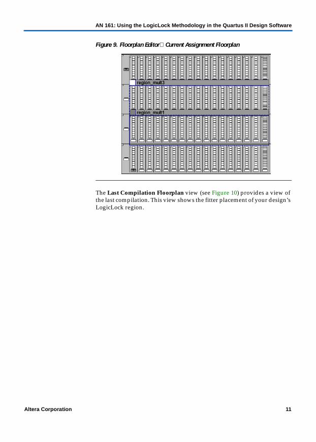
The Current Assignment Floorplan (see Figure 9) view provides you with location assignments (e.g., LCELL, pin, etc,) made by you in either the Assignment Organizer, the Floorplan Editor, or directly in the Compiler Settings File (.csf).
10 Altera Corporation
AN 161: Using the LogicLock Methodology in the Quartus II Design Software
Altera Corporation 11
Figure 9. Floorplan Editor Current Assignment Floorplan
The Last Compilation Floorplan view (see Figure 10) provides a view of the last compilation. This view shows the fitter placement of your design’s LogicLock region.

AN 161: Using the LogicLock Methodology in the Quartus II Design Software
Figure 10. Floorplan Editor Last Compilation
The Timing Closure Floorplan view provides you with current and last compilation assignments on one screen. There are two views in which you can display device resources, namely the field view and the interior cells view (See Figure 11). The field view provides an uncluttered view of the device floorplan where all device resources such as ESBs and MegaLABTM blocks are outlined. The interior cells view displays device resources in a similar fashion to the Current Assignment and the Last Compilation Floorplan views.
Figure 11. Floorplan Editor Timing Closure
(Field View) (Interior Cells View)
12 Altera Corporation

AN 161: Using the LogicLock Methodology in the Quartus II Design Software
LogicLock Region Properties
A LogicLock region is defined by its size (height and width) and location (where the region is located on the device). You can specify the size and/or location of a region, or the Quartus II software can generate them automatically. The Quartus II software bases the size and location of the region on its contents and the module’s timing requirements. Table 1 describes the options for creating LogicLock regions.
Note to Table 1:(1) Default values are floating, auto, off, and hard, respectively.
1 The Quartus II software cannot automatically define a region’s size if the location is locked. Therefore, if you want to specify the exact region location, you must also specify the size. Mercury devices will only support locked and fixed regions.
The floorplan excerpt in Figure 12 shows the LogicLock region properties for a design implemented in a Stratix device.
Table 1. Types of LogicLock Regions
Properties Values (1) Behavior
State Floating, Locked
Floating regions allow the Quartus II software to determine the region’s location on the device. Locked regions represent user-defined locations of a region and are illustrated with a solid boundary in the graphical floorplans. A locked region must have a fixed size.
Size Auto, Fixed Auto-sized regions allow the Quartus II software to determine the appropriate size of a region given its contents. Fixed regions have a user-defined shape and size.
Reserved Off, On The reserved property allows you to define whether you can use the resources within a region for entities that are not assigned to the region. If the reserved property is on, only items assigned to the region can be placed within its boundaries.
Enforcement Hard, Soft Soft regions give more deference to timing constraints, and allow some entities to leave a region if it improves the performance of the overall design. Hard regions do not allow contents to be placed outside of the boundaries of the region.
Origin Any Floorplan Location
The origin defines the top-left corner of the LogicLock region’s placement on the floorplan.
Altera Corporation 13

AN 161: Using the LogicLock Methodology in the Quartus II Design Software
Figure 12. LogicLock Region Properties
Hierarchical (Parent/Child) LogicLock Regions
With the LogicLock design flow, you can define a hierarchy for a group of regions by declaring parent/child regions. The Quartus II software places a child region completely within the boundaries of its parent region, allowing you to further constrain module locations. Additionally, parent/child regions allow you to further improve a module’s performance by constraining the nodes in the module’s critical path. Figure 13 shows an example child region within a parent region, including labels for a locked location and floating location for a Stratix device.
LLR1 is a fixed, floating region LLR3 is a fixed, locked region
Width of LLR1_CHILDLLR1_CHILD, a child region of LLR1, is a fixed, locked region LLR3 Origin
LLR2 is an auto, floating region LLR3 Height
14 Altera Corporation

AN 161: Using the LogicLock Methodology in the Quartus II Design Software
Figure 13. Child Region within a Parent Region
1 The LogicLock region hierarchy does not have to be the same as the design hierarchy.
A child region’s location can float within its parent or remain locked relative to its parent’s origin, while a locked parent region’s location is locked relative to the device. If the child’s location is locked and the parent’s location is changed, the child’s origin changes but maintains the same placement relative to the origin of its parent. Either you or the Quartus II software can determine a child region’s size; however, it must fit entirely within the parent region.
LLR1_CHILD_1 is a fixed, locked child region LLR1_CHILD_2 is a fixed, floating child region
Altera Corporation 15

AN 161: Using the LogicLock Methodology in the Quartus II Design Software
Assigning LogicLock Region Content
Once you have defined a LogicLock region, you must assign resources to it using the Current Assignments Floorplan, the LogicLock Regions dialog box, the Assignment Organizer, or with Tcl scripts and the Quartus II Tcl Console.
Using Drag & Drop to Place Logic
You can drag and drop logic selected from the Compilation Hierarchy window, Last Compilation Floorplan, Node Finder, or a schematic design file into the Current Assignments Floorplan or the LogicLock Regions dialog box. Figure 14 shows logic that has been dragged and dropped from the Compilation Hierarchies list to the Current Assignments Floorplan.
Figure 14. Drag & Drop Logic in the Current Assignments Floorplan
Figure 15 shows logic that has been dragged and dropped from the Compilation Hierarchies list to the LogicLock Regions dialog box.
Drag and drop from Compilation Hierarchies to LogicLock Regions
16 Altera Corporation

AN 161: Using the LogicLock Methodology in the Quartus II Design Software
Figure 15. Drag & Drop Logic in the LogicLock Regions Dialog Box
1 You must manually assign pins to a LogicLock region. The Quartus II software does not include pins automatically when you assign an entity to a region. The software only obeys pin assignments to locked regions that border the periphery of the device. For Stratix and Cyclone devices, the regions must also include the I/O pins as resources.
Drag and drop from the Compilation Hierarchies window to the region name under LogicLock Regions or onto theDesign Element Assigned dialog box
Altera Corporation 17

AN 161: Using the LogicLock Methodology in the Quartus II Design Software
Using the Assignment Organizer to Place Logic
You can also use the Assignment Organizer to assign entities and nodes to a LogicLock region (see Figure 16). To assign content to a LogicLock region with the Assignment Organizer, perform the following steps:
1. Select the required nodes, entities, or pins on the By Node tab in the Assignment Organizer.
2. Select the required nodes, entities, or pins in the Assignment Organizer.
3. Under Assignment Categories, click the + icon to expand the LogicLock Regions listing.
4. Select Click here to add new assignment.
5. Under Assignment, select the LogicLock region from the Region list and click Add.
The logic is assigned to the selected LogicLock region.
1 Clicking Properties under Assignment displays the LogicLock Regions dialog box with the selected region highlighted.
18 Altera Corporation

AN 161: Using the LogicLock Methodology in the Quartus II Design Software
Figure 16. Assignment Organizer
Quartus II Block-Based Design Flow
As discussed in “Block-Based Design & Design Partitioning” on page 2, when using the LogicLock design flow, first divide the design into modules. Then, perform the following steps in the Quartus II software for each module:
1. Synthesize the module using the Quartus II software or another synthesis tool.
2. Optimize the module in the Quartus II software.
3. Export the module and the LogicLock constraints.
4. Import all modules and LogicLock constraints into the top-level project.
5. Compile and verify the top-level design.
Altera Corporation 19
AN 161: Using the LogicLock Methodology in the Quartus II Design Software
Synthesize the Module
You can synthesize the modules in the Quartus II software or any Altera-supported third-party synthesis tool, e.g., the Synplify® LeonardoSpectrumTM, or FPGA Compiler II software. The software synthesizes each module into an ATOM netlist, which represents the logic in terms of Altera primitives for the target Altera device.
In the ATOM netlist, the nodes are fixed as Altera primitives; the node names do not change if the ATOM netlist does not change. If a node name does change, any placement information made to that node is invalid and ignored. Third-party tools generate ATOM netlists as EDIF Input Files (.edf) or Verilog Quartus Mapping Files (.vqm).
Optimize the Module
Before optimizing a module in the Quartus II software, create a project with the module as the top-level entity. You must assign the module to a single (or multiple) LogicLock region. Refer to “Constraint Priority” on page 34 for information on the precedence of the LogicLock region and other constraint settings.
After you have optimized the module so that it meets timing requirements, lock down the placement of nodes in a LogicLock region by back-annotating the contents of the region to reproduce the module’s performance when imported by a higher-level project. To make relative location assignments, the node names must be fixed, which requires an ATOM netlist, so that the assignments for each node remain valid. The node placement is fixed relative to the LogicLock region for the module.
1 For the Quartus II software to achieve optimal placement, you should make timing assignments for all clock signals in the design, e.g., tSU, tCO, and tPD.
To facilitate the LogicLock design flow, the Current Assignments Floorplan highlights resources that have back-annotated LogicLock regions. Figure 17 shows a back-annotated LogicLock region in the Current Assignments Floorplan.
20 Altera Corporation

AN 161: Using the LogicLock Methodology in the Quartus II Design Software
Figure 17. Back-Annotated LogicLock Region
Export the Module
This section describes how to export a module’s constraints to a format that can be imported by a top-level design. To be exported, a module requires design information as an ATOM netlist (VQM or EDF) and placement information stored in a Quartus II Entity Settings File (.esf).
ATOM Netlist Design Information
The ATOM netlist contains design information that fully describes the module’s logic in terms of an Altera device architecture. If the design was synthesized using a third-party tool and then brought into the Quartus II software, an ATOM netlist already exists and the node names are fixed. You do not need to generate another ATOM netlist.
1 If the ATOM netlist is from third-party synthesis tools and the design has black-boxed library of parameterized modules (LPM) functions or Altera megafunctions, you must generate a Quartus II VQM File for the black-boxed modules.
Used resources in a LogicLock region are highlighted
Unused regions are nothighlighted
Altera Corporation 21

AN 161: Using the LogicLock Methodology in the Quartus II Design Software
If you synthesized the design as a VHDL Design File (.vhd), Verilog Design File (.v), Text Design File (.tdf), or a Block Design File (.bdf) in the Quartus II software, you must also create an ATOM netlist to fix the nodes and node names. During compilation, the Quartus II software creates a VQM File in the atom_netlists subdirectory in the project directory.
f For instructions on creating an ATOM netlist in the Quartus II software, refer to the topic “Saving Synthesis Results for an Entity to a Verilog Quartus Mapping File” in Quartus II Help.
When you export LogicLock regions, the Quartus II software defaults to exporting your entire design’s LogicLock region assignments. However, you can export a sub-entity of the compilation hierarchy and all of its relevant regions. You can export individual regions by specifying the entire sub-entity hierarchy into the Export focus full hierarchy path field in the Export LogicLock Regions window.
Placement Information
The ESF contains the module’s LogicLock constraint information, including clock settings, pin assignments, and relative placement information for back-annotated regions. To maintain performance, you must back-annotate the module.
f For instructions on exporting a LogicLock region assignment in the Quartus II software, refer to the topic “Exporting LogicLock Region Assignments and Other Entity Assignments” in Quartus II Help.
Import the Module
The Quartus II software gives you the option to specify which ESF is used for a specific instance or entity using the LogicLock Import File Name option in the Assignment Organizer. Therefore, you can specify different LogicLock region constraints for each instance of an entity and import them into the top-level design.
1 You do not have to specify an ESF. If you do not specify it, the Quartus II software searches the top-level directory for an ESF with the same name as any of the entities in the design.
When importing LogicLock regions into the top-level design, the Quartus II software finds the ESF (user-specified or located in the top-level directory) for the modules in the project. If the design instantiates a module multiple times, the Quartus II software applies the LogicLock regions multiple times.
22 Altera Corporation
AN 161: Using the LogicLock Methodology in the Quartus II Design Software
1 Before importing LogicLock regions, you must perform an Analysis & Elaboration or compile the top-level design so that the Quartus II software is aware of all instances of the lower-level modules.
The following sections describe how to specify an ESF for a module and how to import the LogicLock assignments into the top-level design.
Specify the ESF
To specify an ESF for importing:
1. Perform Analysis & Elaboration if you have not already done so.
2. Expand the design hierarchy on the Project Navigator Hierarchies tab by clicking the + icon next to the top-level entity.
3. Right-click the entity and choose Assignment Organizer.
4. Click the + icon next to Options for Entities Only.
5. Select Click here to add new assignment.
6. In the Name list under Assignment, choose LogicLock Import File Name.
7. In the Setting box, type in the name and relative path to the ESF.
Repeat steps 3 through 7 for all entities that require a specific ESF.
Import the Assignments
To import the assignments, choose LogicLock Regions (Assignments menu) and click Import. The Import dialog box opens. See Figure 18.
Altera Corporation 23

AN 161: Using the LogicLock Methodology in the Quartus II Design Software
Figure 18. Import Dialog Box
To control the import flow of LogicLock regions, the Quartus II software has a number of options available in the Import LogicLock Regions window. See Table 2.
Table 2. Import LogicLock Options (Part 1 of 2)
Import Option Description
Import LogicLock region assignments and other node or entity assignments
Allows the importing of all entity options including LogicLock, timing, and logic assignments.
Only import LogicLock region assignments
Allows only the importing of LogicLock and region placement information.
Only import other node or entity assignments
Allows only the importing of timing and logic options.
Create new LogicLock regions and update the currently selected LogicLock region(s)
Creates new LogicLock regions for regions that currently do not exist in the design, but exist in the specified ESF. This option will also update the currently selected LogicLock region properties with those in the specified ESF. (1)
24 Altera Corporation

AN 161: Using the LogicLock Methodology in the Quartus II Design Software
Note to Table 2:(1) Only the selected LogicLock region will be updated. Therefore, if you want both the
parent and child region to be updated, select both the parent and child region in the LogicLock window.
The Quartus II software converts all imported regions to floating regions to prevent erroneous no-fit errors. This setting allows the Quartus II software to move LogicLock regions to areas on the device with free resources. Child regions are locked or floating relative to their parent region’s origin as specified in the modules’ original LogicLock constraints.
1 If you want to lock a LogicLock region to a location, you can manually lock down the region in the LogicLock Regions dialog box or the Current Assignments Floorplan.
Each LogicLock region has a name that corresponds to the original LogicLock region name combined with the instance name in the form of <original LogicLock region name>_<instance name>. For example, if a LogicLock region for a module is named LLR_0 and the instance name for the module is Filter:inst1, the LogicLock region name in the top-level design is LLR_0_Filter:inst1.
Compile & Verify the Top-Level Design
After importing all modules, you can compile and verify the top-level design. The compilation report shows whether system timing requirements have been met.
Create new LogicLock regions, but do not update the currently selected LogicLock region(s)
Creates new LogicLock regions for regions that currently do not exist in the design, but do exist in the specified ESF. This option will not update the currently selected LogicLock region.
Do not create new LogicLock regions, only update the currently selected LogicLock region(s)
Does not create new LogicLock regions for regions that currently do not exist in the design, but exist in the specified ESF. This option will also update the currently selected LogicLock region properties with those in the specified ESF. (1)
Table 2. Import LogicLock Options (Part 2 of 2)
Import Option Description
Altera Corporation 25

AN 161: Using the LogicLock Methodology in the Quartus II Design Software
Additional Quartus II LogicLock Design Features
To complement the LogicLock Regions dialog box and device floorplan view, the Quartus II software has additional options to help you design with the LogicLock feature.
Tooltips
When you move the mouse so that the pointer is over a LogicLock region name in the Hierarchy window or LogicLock Regions dialog box, or over the top bar in the Current Assignments Floorplan, Last Compilation Floorplan, or Timing Closure Floorplan, the Quartus II software displays tooltips with information about the properties of the LogicLock region.
1 Placing the mouse over Fitter Placed LogicLock Regions will also display the maximum routing delay within the LogicLock region. You must first initiate the Show Critical Paths (see “Show Critical Paths” on page 28) feature before the delay information becomes available.
Repair Branch
When you retarget your design to either a larger or smaller device, there is a chance that your LogicLock regions will no longer contain valid values for location or size in the new device, resulting in an illegal LogicLock region. The Quartus II software identifies illegal LogicLock regions in the LogicLock Regions dialog box by coloring the offending region’s name red.
To correct the illegal LogicLock region, you can use the Repair Branch command. The Repair Branch command can be found by right clicking on any LogicLock region’s name.
1 If more then one illegal LogicLock region exists, you can repair all regions by right clicking the first line in the LogicLock window that contains the text LogicLock Regions and selecting Repair Branch.
26 Altera Corporation

AN 161: Using the LogicLock Methodology in the Quartus II Design Software
Reserve LogicLock Region
The Quartus II software honors all entities and node assignments to LogicLock regions. Occasionally, entities and nodes will not occupy an entire region, which leaves some of the region’s resources unoccupied. To increase the region’s resource utilization and performance, the Quartus II software’s default behavior fills the unoccupied resources with other nodes and entities in the design that have not been assigned to any other region. You can prevent this behavior by turning on Reserve unused logic cells on the Contents tab of the LogicLock Region Properties dialog box. With this property enabled, your LogicLock region only contains the entities and nodes that you have specifically assigned to your LogicLock region.
In a team-based design environment, this property is extremely helpful in device floorplanning. With this property enabled, each team can be assigned a portion of the device floorplan where placement and optimization of each submodule occurs. Device resources can be distributed to every module without affecting the performance of other modules.
Prevent Assignment to LogicLock Regions Option
The Prevent Assignment to LogicLock Regions option allows you to exclude any arbitrary entity or node from being a member of any LogicLock region. However, it does not prevent the entity or node from entering into LogicLock regions. Essentially, you can place the entity or node anywhere on the device as if no regions exist.
1 The Prevent Assignment to LogicLock Region option is found in the Assignment Organizer under the Options for Individual Nodes & Entities.
LogicLock Regions Connectivity
The Quartus II Floorplan Editor allows you to see connections between various LogicLock regions that exist within a design. The connection between the regions will be drawn as a single line between the LogicLock regions. The thickness of this line is proportional to the number of connections between the regions.
Rubber Banding
With the Rubber Banding option enabled, the Quartus II software shows existing connections between LogicLock regions and nodes during movement of LogicLock regions within the Floorplan Editor.
Altera Corporation 27

AN 161: Using the LogicLock Methodology in the Quartus II Design Software
Show Critical Paths
You can display the critical paths within a LogicLock region by enabling the Show Critical Paths option. This option is used in conjunction with the Critical Paths Settings option that allows you to display either one or more of the following: pin-to-pin, pin-to-register, register-to-pin, or register-to-register paths. See Figure 19.
Figure 19. Show Critical Paths & Critical Paths Settings
Show Connection Count
You can determine the number of connections between LogicLock regions by enabling the Show Connection Count option.
Post-Synthesis Resource Utilization by Entity
The Compilation Report provides information on the Post-Synthesis Resource Utilization by Entity, which gives you accurate resource usage statistics, including information at the entity level. This feature is useful for manually creating LogicLock regions. See Figure 20.
Show Critical Paths
Critical Paths Settings
28 Altera Corporation

AN 161: Using the LogicLock Methodology in the Quartus II Design Software
Figure 20. Post-Synthesis Resource Utilization by Entity
Refer to the topic “Post-Synthesis Resource Utilization by Entity Section (Compilation Report)” in Quartus II Help for more information.
Path-Based Assignments
The Quartus II software enables you to assign paths to LogicLock regions based on source and destination nodes, allowing for easy grouping of critical design nodes into a LogicLock region. The path’s source and destination nodes must be a valid register-to-register path, meaning that the source and destination node must be a register. See Figure 21.
1 Both “*” and “?” wildcard settings are allowed for both the source and destination nodes.
Altera Corporation 29

AN 161: Using the LogicLock Methodology in the Quartus II Design Software
Figure 21. Path-Based Assignment Dialog Box
1 The Path Based Assignment dialog box is launched from the Contents Tab of the LogicLock Regions dialog box.
Quartus II Archive & Restore Utility
The Quartus II software has a built-in archive and restore utility, which is useful for LogicLock design flows. For example, when you create, modify, or import LogicLock regions into top-level designs, you may need to experiment with different configurations. The archive and restore utility allows you to archive and restore projects with different constraints until the optimum configuration is found.
30 Altera Corporation

AN 161: Using the LogicLock Methodology in the Quartus II Design Software
Priority-Based Assignments
Conflicts might arise during the assignment of entities and nodes to LogicLock regions. For example, an entire top-level entity might be assigned to one region and a node within this top-level entity assigned to another region. To resolve this type of conflicting assignments, the Quartus II software maintains an order of precedence during LogicLock assignments. The Quartus II software’s order of precedence is as follows:
1. Exact node-level assignments
2. Path-based and wildcard assignments
3. Hierarchical assignments
However, conflicts might also occur within path-based and wildcard assignments. Path-based and wildcard assignment conflicts arise when one path-based or wildcard assignment contradicts another path-based or wildcard assignment. For example, a path-based assignment is made containing a node labeled X and assigned to LogicLock region PATH_REGION. A second assignment is made using wildcard assignment X* with node X being placed into region WILDCARD_REGION. As a result of these two assignments, node X is assigned to two regions: PATH_REGION and WILDCARD_REGION.
To resolve this type of conflict, the Quartus II software remembers the order in which the assignments were made and treats the last assignment created with the highest priority.
1 The Priority dialog box can be found by selecting Priority on the Contents tab. You can order the priority of path-based and wildcard assignments by using the Up or Down buttons in the Priority dialog box. Only path-based and wildcard assignments will appear under the priority for the currently selected region.
LogicLock Regions vs. Soft LogicLock Regions
LogicLock regions have boundaries where nodes assigned to a particular region always reside within a predefined boundary or LogicLock region size. Soft LogicLock regions can enhance design performance by removing the fixed rectangular boundaries of LogicLock regions. With this property enabled, the Quartus II software attempts to place as many nodes assigned to the region as close together as possible, and has the added flexibility of moving nodes outside of the soft region to meet your design’s performance requirement.
Altera Corporation 31

AN 161: Using the LogicLock Methodology in the Quartus II Design Software
Nodes and LogicLock regions that are assigned to a soft region are able to move around the entire device. However, soft regions and descendents and nodes of the soft regions never leave the boundaries of its first non-soft parent region. If a non-soft parent does not exist, the region will float within the boundaries of the device. You can enable this property through the Location tab in LogicLock Region Properties dialog box by selecting Soft Region.
1 Soft regions can have an arbitrary hierarchy that allows for any combination of parent and child to be a soft region.
The Reserved option is not compatible with soft regions.
LogicLock regions that are defined as soft regions cannot be back- annotated. The Quartus II software may have placed nodes outside of the LogicLock region resulting in undefinable location assignments relative to the region’s origin and size.
Soft regions are available for all device families that support floating LogicLock regions.
Virtual Pins
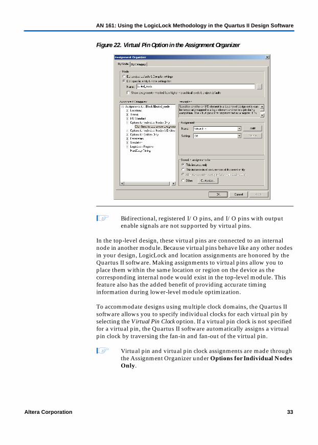
When you compile a design in the Quartus II software, all I/O ports are directly mapped to a pin on the targeted device. This I/O port mapping may create problems for a modular/hierarchical design because lower-level modules may have more I/O ports than pins available on the targeted device. Many of these I/O ports will not directly feed into a device pin, but are used to drive internal nodes. The Quartus II software supports virtual pins to accommodate this situation. Virtual pin assignments direct the Quartus II software which I/O ports of the design module become internal nodes in the top-level design. These assignments prevent the number of I/O ports in the lower-level module from exceeding the total number of available device pins. Every I/O port that is designated as a virtual pin will get mapped to an LCELL register in the Altera device. Figure 22 shows the floorplan view for virtual pins.
32 Altera Corporation
AN 161: Using the LogicLock Methodology in the Quartus II Design Software
Figure 22. Virtual Pin Option in the Assignment Organizer
1 Bidirectional, registered I/O pins, and I/O pins with output enable signals are not supported by virtual pins.
In the top-level design, these virtual pins are connected to an internal node in another module. Because virtual pins behave like any other nodes in your design, LogicLock and location assignments are honored by the Quartus II software. Making assignments to virtual pins allow you to place them within the same location or region on the device as the corresponding internal node would exist in the top-level module. This feature also has the added benefit of providing accurate timing information during lower-level module optimization.
To accommodate designs using multiple clock domains, the Quartus II software allows you to specify individual clocks for each virtual pin by selecting the Virtual Pin Clock option. If a virtual pin clock is not specified for a virtual pin, the Quartus II software automatically assigns a virtual pin clock by traversing the fan-in and fan-out of the virtual pin.
1 Virtual pin and virtual pin clock assignments are made through the Assignment Organizer under Options for Individual Nodes Only.
Altera Corporation 33
AN 161: Using the LogicLock Methodology in the Quartus II Design Software
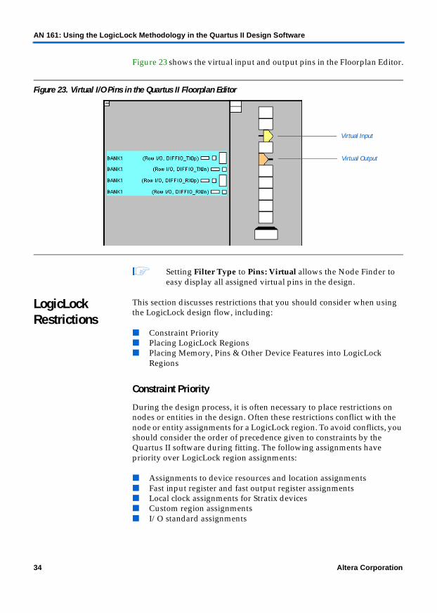
Figure 23 shows the virtual input and output pins in the Floorplan Editor.
Figure 23. Virtual I/O Pins in the Quartus II Floorplan Editor
1 Setting Filter Type to Pins: Virtual allows the Node Finder to easy display all assigned virtual pins in the design.
LogicLock Restrictions
This section discusses restrictions that you should consider when using the LogicLock design flow, including:
■ Constraint Priority■ Placing LogicLock Regions■ Placing Memory, Pins & Other Device Features into LogicLock
Regions
Constraint Priority
During the design process, it is often necessary to place restrictions on nodes or entities in the design. Often these restrictions conflict with the node or entity assignments for a LogicLock region. To avoid conflicts, you should consider the order of precedence given to constraints by the Quartus II software during fitting. The following assignments have priority over LogicLock region assignments:
■ Assignments to device resources and location assignments■ Fast input register and fast output register assignments■ Local clock assignments for Stratix devices■ Custom region assignments■ I/O standard assignments
Virtual Input
Virtual Output
34 Altera Corporation

AN 161: Using the LogicLock Methodology in the Quartus II Design Software
The Quartus II software can remove nodes and entities from LogicLock regions if any of these constraints are applied to them.
Placing LogicLock Regions
Although the Quartus II software can automatically place and size LogicLock regions to meet resource and timing requirements, you can manually place and size regions to meet your design needs. When manually placing and sizing regions, follow these guidelines:
■ A fixed region must contain all of the resources required for the module.
■ LogicLock regions with pin assignments must be placed on the periphery of the device, adjacent to the pins. (For Stratix and Cyclone devices, you must also include the I/O block.)
■ Floating LogicLock regions cannot overlap.■ You can create fixed and locked regions that overlap.■ After back-annotating a region, the software can only place the region
in areas on the device with exactly the same resources.
1 This guideline is particularly important if you want to import multiple instances of the module into a top-level design, because you must ensure that the device has two or more locations with exactly the same device resources. If the device does not have another area with exactly the same resources, the top-level design generates a no-fit error during compilation.
Figure 24 shows a floorplan with two instantiations of the same module. Both modules have the same LogicLock constraints and require exactly the same resources. The Quartus II software places the two LogicLock regions in different areas in devices that have the same resources.
Altera Corporation 35

AN 161: Using the LogicLock Methodology in the Quartus II Design Software
Figure 24. Floorplan of Two Instances of a LogicLock Region
The back-annotated regions LLR1_Inst1 and LLR1_Inst2 have the same resources.
LLR1_Inst1
LLR1_Inst2
36 Altera Corporation

AN 161: Using the LogicLock Methodology in the Quartus II Design Software
Placing Memory, Pins & Other Device Features into LogicLock Regions
A LogicLock region includes all device resources within its boundaries. You can assign pins to LogicLock regions; however, this placement makes location constraints on the region. When the Quartus II software places a floating automatically sized region, it places the region in an area that meets the requirements of the LogicLock region’s contents.
1 Pin assignments to LogicLock regions only honor fixed and locked regions. Pins assigned to floating regions do not influence the region’s placement.
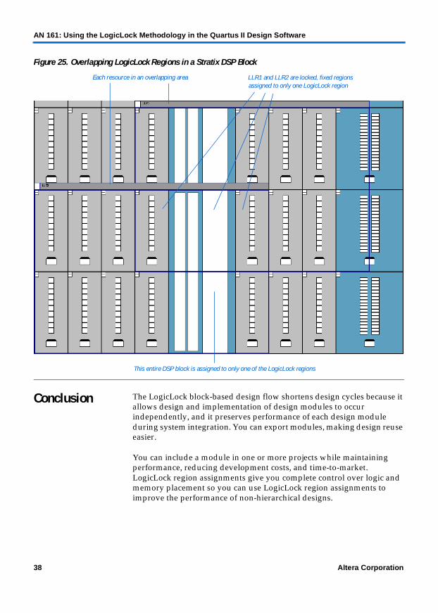
Only one LogicLock region can claim a device resource. If the boundary includes part of a device resource, such as a DSP block, the Quartus II software allocates the entire resource to the LogicLock region. Figure 25 shows two overlapping regions in the same Stratix DSP block. The Quartus II software can assign this resource to only one of the LogicLock regions. The region’s resource requirements determine which region gets the assignment. If both regions require a DSP block, the Quartus II software issues a no fit error.
Altera Corporation 37
AN 161: Using the LogicLock Methodology in the Quartus II Design Software
Figure 25. Overlapping LogicLock Regions in a Stratix DSP Block
Conclusion The LogicLock block-based design flow shortens design cycles because it allows design and implementation of design modules to occur independently, and it preserves performance of each design module during system integration. You can export modules, making design reuse easier.
You can include a module in one or more projects while maintaining performance, reducing development costs, and time-to-market. LogicLock region assignments give you complete control over logic and memory placement so you can use LogicLock region assignments to improve the performance of non-hierarchical designs.
LLR1 and LLR2 are locked, fixed regions
This entire DSP block is assigned to only one of the LogicLock regions
Each resource in an overlapping area assigned to only one LogicLock region
38 Altera Corporation

Copyright © 2002 Altera Corporation. All rights reserved. Altera, The Programmable Solutions Company, thestylized Altera logo, specific device designations, and all other words and logos that are identified astrademarks and/or service marks are, unless noted otherwise, the trademarks and service marks of AlteraCorporation in the U.S. and other countries. All other product or service names are the property of theirrespective holders. Altera products are protected under numerous U.S. and foreign patents and pendingapplications, maskwork rights, and copyrights. Altera warrants performance of itssemiconductor products to current specifications in accordance with Altera’s standardwarranty, but reserves the right to make changes to any products and services at any timewithout notice. Altera assumes no responsibility or liability arising out of the applicationor use of any information, product, or service described herein except as expressly agreedto in writing by Altera Corporation. Altera customers are advised to obtain the latestversion of device specifications before relying on any published information and beforeplacing orders for products or services.
AN 161: Using the LogicLock Methodology in the Quartus II Design Software
39 Altera Corporation
101 Innovation DriveSan Jose, CA 95134(408) 544-7000http://www.altera.comApplications Hotline:(800) 800-EPLDLiterature Services:[email protected]
References For more information on the LogicLock design methodology and EDA tool flows, refer to the following documents:
■ AN 164: LeonardoSpectrum & Quartus II LogicLock Design Flow■ AN 165: Synplify & Quartus II LogicLock Design Flow■ AN 171: FPGA Compiler II BLIS & the Quartus II LogicLock Design Flow■ AN 225: LeonardoSpectrum & Quartus II Design Methodology■ AN 226: Synplify & Quartus II Design Methodology
Contact Information
For technical support, contact Altera Applications at (800) 800-EPLD or access mySupport at http://mysupport.altera.com.
Revision History
The information contained in AN 161: Using the LogicLock Methodology in the Quartus II Design Software version 3.2 supersedes information published in previous versions.
Version 3.2
AN 161: Using the LogicLock Methodology in the Quartus II Design Software version 3.2 contains the following changes:
■ Updated text on pages 1 and 23.■ Updated illustrations throughout to reflect new user interface
features in the Quartus II software version 2.2.
Version 3.1
AN 161: Using the LogicLock Methodology in the Quartus II Design Software version 3.1 contains the following changes:
■ Updated text on page 1.■ Updated text on page 6.■ Updated text on page 35.