amy robertson trondheim, norway february 5, 2015 · swe simpack +hydrodyn linear airy me no utokyo...
TRANSCRIPT

NREL is a national laboratory of the U.S. Department of Energy, Office of Energy Efficiency and Renewable Energy, operated by the Alliance for Sustainable Energy, LLC.
Introduction to the OC5 Project, an IEA Task Focused on Validating Offshore Wind Modeling Tools
Amy Robertson
Trondheim, Norway
February 5, 2015

2
Offshore Wind Modeling Tools
Wind Turbine & Support StructureApplied
Loads
External
Conditions
Soil
Hydro-
dynamics
Aero-
dynamics
Waves &
Currents
Wind-InflowPower
Generation
Rotor
Dynamics
Substructure Dynamics
Foundation Dynamics
Drivetrain
Dynamics
Control System
Soil-Struct.
Interaction
Nacelle Dynamics
Tower Dynamics
• OWTs are designed using aero-hydro-servo-elastic tools
• The tools must be verified and validated to assess their accuracy
3
Spar Concept by SWAY
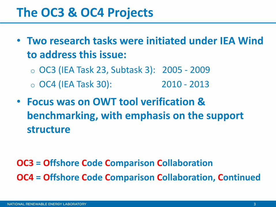
The OC3 & OC4 Projects
• Two research tasks were initiated under IEA Wind to address this issue:
o OC3 (IEA Task 23, Subtask 3): 2005 - 2009
o OC4 (IEA Task 30): 2010 - 2013
• Focus was on OWT tool verification & benchmarking, with emphasis on the support structure
OC3 = Offshore Code Comparison Collaboration
OC4 = Offshore Code Comparison Collaboration, Continued
4
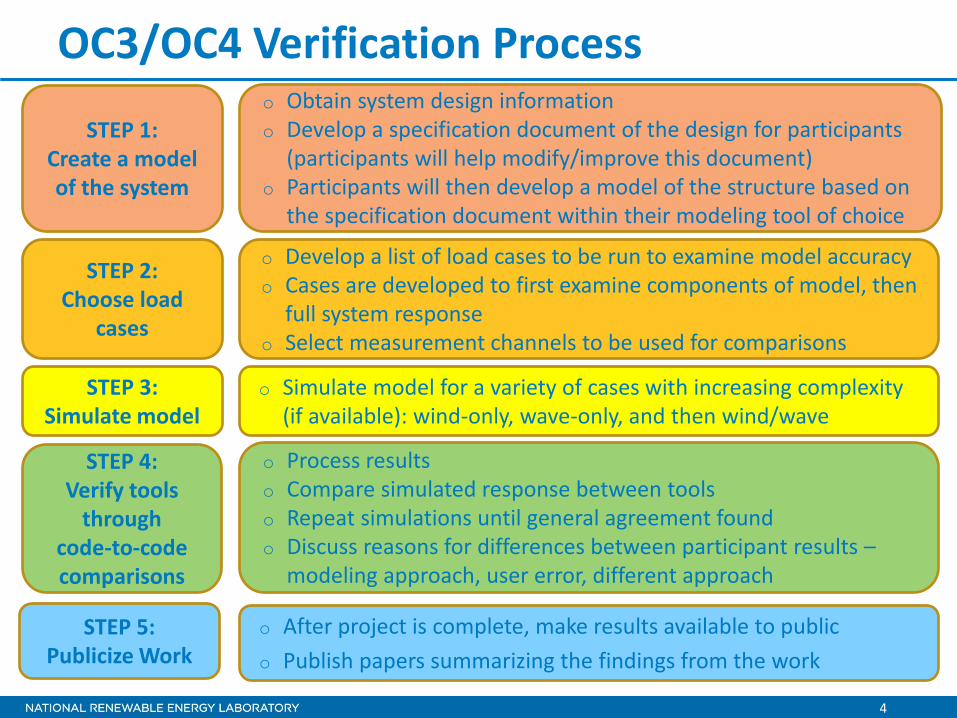
OC3/OC4 Verification Process
STEP 1: Create a model of the system
STEP 2: Choose load
cases
STEP 3: Simulate model
STEP 4: Verify tools
through code-to-code comparisons
o Obtain system design information o Develop a specification document of the design for participants
(participants will help modify/improve this document) o Participants will then develop a model of the structure based on
the specification document within their modeling tool of choice
o Develop a list of load cases to be run to examine model accuracy o Cases are developed to first examine components of model, then
full system response o Select measurement channels to be used for comparisons
o Simulate model for a variety of cases with increasing complexity (if available): wind-only, wave-only, and then wind/wave
o Process results o Compare simulated response between tools o Repeat simulations until general agreement found o Discuss reasons for differences between participant results –
modeling approach, user error, different approach
STEP 5: Publicize Work
o After project is complete, make results available to public
o Publish papers summarizing the findings from the work

5
Fixed-Bottom Floating
The OC3/OC4 Systems Examined

6
Company Simulation Tool
4Subsea OrcaFlex ABS CHARM3D + FAST CENER OPASS + FAST CENTEC FAST CeSOS (NTNU) Simo+Riflex+Aerodyn CGC Bladed 4.3 DHI WAMSIM DTU HAWC2 GH Bladed 4.4 /Bladed Advanced Hydro Beta Goldwind FAST IFE 3DFLOAT IST FAST LMS-IREC SWT MARINTEK RIFLEX-Coupled NTUA hydro-GAST NREL FAST POSTECH GH Bladed PRINCIPIA DeepLinesWT SWE SIMPACK +HydroDyn Univ. of Tokyo CAST Univ. of Ulsan UOU + FAST WaveEC Wavec2Wire
OC4 Phase II Participants & Tools
7
Spar Concept by SWAY
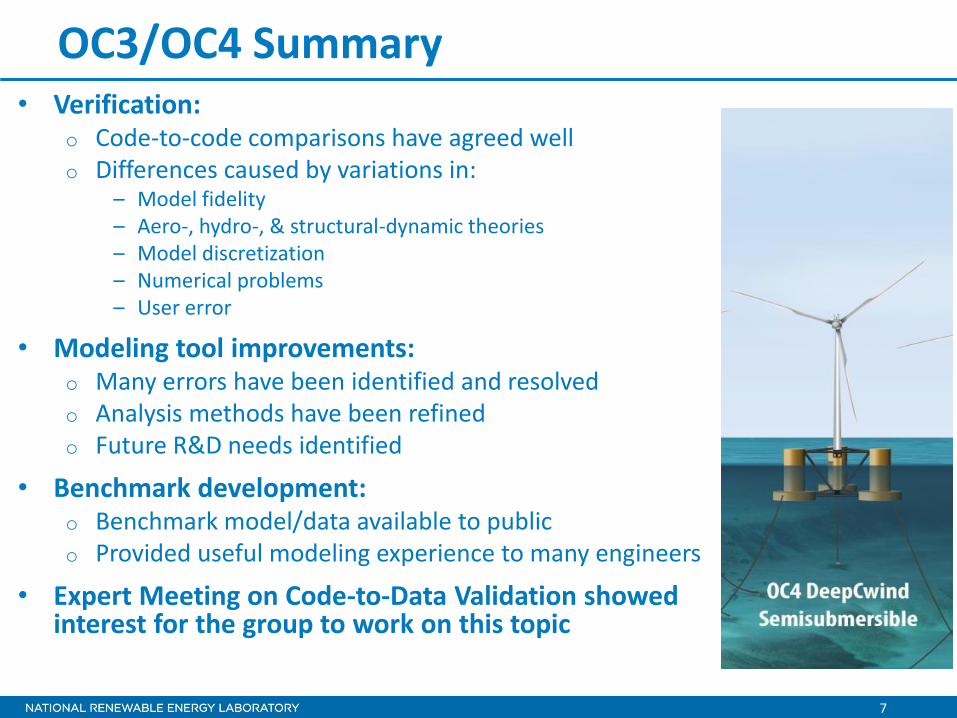
OC3/OC4 Summary • Verification:
o Code-to-code comparisons have agreed well o Differences caused by variations in:
– Model fidelity – Aero-, hydro-, & structural-dynamic theories – Model discretization – Numerical problems – User error
• Modeling tool improvements: o Many errors have been identified and resolved o Analysis methods have been refined o Future R&D needs identified
• Benchmark development: o Benchmark model/data available to public o Provided useful modeling experience to many engineers
• Expert Meeting on Code-to-Data Validation showed interest for the group to work on this topic

8
0 10 20 30 40 50
-1.5
-1
-0.5
0
0.5
1
1.5
2
Time (sec)
Ptfm
Su
rge
(m)
4Subsea_P
ABS
CENER
CENTEC
CGC
CSIC
CeSOS
DTU
GH
GH Adv
Goldwind
IFE
IST
IST2
MARINTEK
NREL
NTUA
NTUA_M
POSTECH
PRINCIPIA_M
PRINCIPIA_P
SWE
U-TOKYO
UOU
WavEC
For both ME and PF approaches,
mean drift loads need to be
considered.
Pla
tform
Surg
e M
otion
(m
) Results – LC 2.1 – Regular Waves

9
OC5 – Simulation Tool Validation • OC5 = Offshore Code Comparison Collaboration, Continued, with
Correlation o Code-to-data validation of offshore wind modeling tools
o Extension of IEA Wind Task 30: 2014-2018
o Three phases – examining three different systems
Monopile - Tank Testing Semi - Tank Testing Jacket/Tripod – Open Ocean

10
Timeline
Phase Description Timeline
Phase Ia MARINTEK Cylinder June 2014 – Feb. 2015
Phase 1b DTU/DHI Cylinder Feb. 2015 – June 2015
Phase II DeepCwind
Semisubmersible June 2015 – June 2016
Phase III Open Ocean System June 2016 – June 2017
11
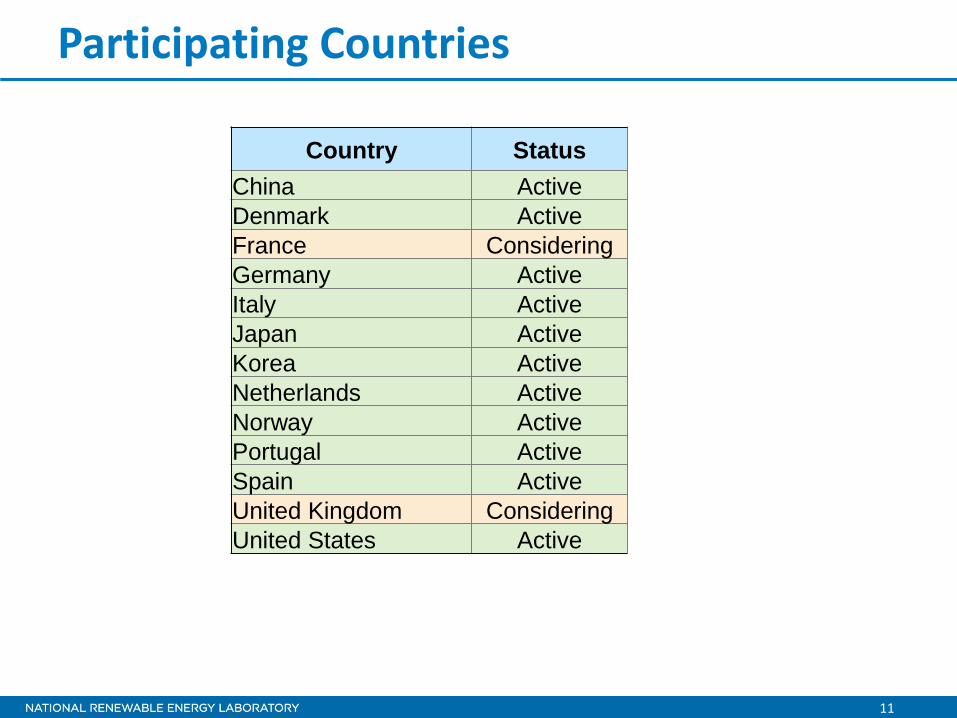
Participating Countries
Country Status
China Active
Denmark Active
France Considering
Germany Active
Italy Active
Japan Active
Korea Active
Netherlands Active
Norway Active
Portugal Active
Spain Active
United Kingdom Considering
United States Active

12
OC5 Validation Project Process
STEP 1: Create a model of the system
STEP 2: Choose data sets for comparison
STEP 3: Calibrate the model
STEP 4: Validate the model
o Obtain system design information
o Develop a specification document of the design for participants (participants will help modify/improve this document)
o Participants will then develop a model of the structure based on the specification document within their modeling tool of choice
o Create a list of available datasets, including specifics on wind/waves
o Group will down-select data sets to be used for calibration and validation
o Select measurement channels to be used for comparisons
o Calibration will be done as a group.
o Run structural-only cases, and calibrate model properties (mass/stiffness) using natural frequencies, structural damping rations, mooring force-disp.
o Run steady wind-only cases, and calibrate airfoil coefficients using rotor performance (power, torque, thrust)
o Run wave-only cases, and calibrate hydrodynamic coefficients using free-decay tests, current-only tests, and wave-only tests
o Simulate model for a variety of cases with increasing complexity (if available): wind-only, wave-only, and then wind/wave
o Do not use datasets used for calibration
o Compare simulated response to that of the measurements
o Discuss differences between participant results and tests

13
Phase I - Monopile
• Phase I examines monopile
o No wind turbine
o Fixed structure
o Tank tests
• Two data sources:
o MARINTEK testing
o DTU/DHI testing

14
MARINTEK Tests
+X
+Z
• Single steel cylinders with varying diameter
o Draft = 1.44 m
o Water depth = 10 m
• Cylinders attached to a steel framework
o Attachment through two force transducers (T1 and T2)
o Vertical and transverse motion restricted by stiffener rods
o Eigenfrequencies > 10 Hz
o Consider framework as rigid
o Free surface on bottom, pierces water line

15
Datasets simulated in OC5 project
OC5 Test No.
Original Test No.
Condition Diameter (m) H/Hs (m) T/Tp (s) Gamma*
1 441 Regular 0.2 0.15 1.533
2 444 Regular 0.2 0.23 1.533
3 442 Regular 0.2 0.28 1.533
4 445 Regular 0.2 0.37 1.533
5 341 Regular 0.327 0.15 1.533
6 344 Regular 0.327 0.23 1.533
7 342 Regular 0.327 0.28 1.533
8 345 Regular 0.327 0.37 1.533
9 431 Regular 0.2 0.282 2.114
10 433 Regular 0.2 0.45 2.114
11 432 Regular 0.2 0.522 2.114
12 434 Regular 0.2 0.6 2.114
13 1331 Regular 0.327 0.282 2.114
14 333 Regular 0.327 0.450 2.114
15 332 Regular 0.327 0.522 2.114
16 334 Regular 0.327 0.6 2.114
17 401 Irregular 0.2 0.279 2.4 1.7
18 4301 Irregular 0.327 0.279 2.4 1.7
19 402 Irregular 0.2 0.357 2.76 1.7
20 4302 Irregular 0.327 0.357 2.76 1.7
*Gamma = peak enhancement factor for a JONSWAP spectrum
16
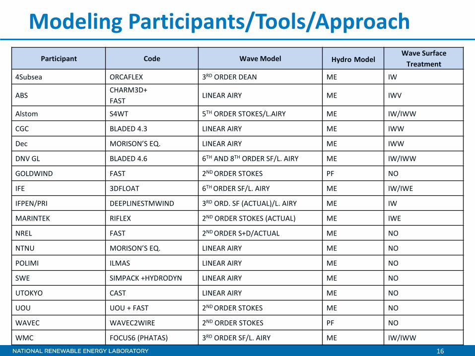
Modeling Participants/Tools/Approach
Participant Code Wave Model Hydro Model Wave Surface
Treatment
4Subsea ORCAFLEX 3RD ORDER DEAN ME IW
ABS CHARM3D+
FAST LINEAR AIRY ME IWV
Alstom S4WT 5TH ORDER STOKES/L.AIRY ME IW/IWW
CGC BLADED 4.3 LINEAR AIRY ME IWW
Dec MORISON’S EQ. LINEAR AIRY ME IWW
DNV GL BLADED 4.6 6TH AND 8TH ORDER SF/L. AIRY ME IW/IWW
GOLDWIND FAST 2ND ORDER STOKES PF NO
IFE 3DFLOAT 6TH ORDER SF/L. AIRY ME IW/IWE
IFPEN/PRI DEEPLINESTMWIND 3RD ORD. SF (ACTUAL)/L. AIRY ME IW
MARINTEK RIFLEX 2ND ORDER STOKES (ACTUAL) ME IWE
NREL FAST 2ND ORDER S+D/ACTUAL ME NO
NTNU MORISON’S EQ. LINEAR AIRY ME NO
POLIMI ILMAS LINEAR AIRY ME NO
SWE SIMPACK +HYDRODYN LINEAR AIRY ME NO
UTOKYO CAST LINEAR AIRY ME NO
UOU UOU + FAST 2ND ORDER STOKES ME NO
WAVEC WAVEC2WIRE 2ND ORDER STOKES PF NO
WMC FOCUS6 (PHATAS) 3RD ORDER SF/L. AIRY ME IW/IWW

17
Calibration Methods Participant Wave Ht Tuning Cd/Ca Calibration Cd/Ca Extrapolation
4SUBSEA Manual tuning 1.0/Manual 1.0/KC-based
ABS Ave. peaks/troughs 1.0/Least squares 1.0/Re and KC-based
ALSTOM Ave. peaks/troughs Weighted least squares DNV
CGC Ave. peaks/troughs Least squares Re and KC-based
DEC Least squares Least squares Re-based
DNV GL Ave. peaks/troughs 0.0/Least squares 0.0/Re-based
Goldwind Ave. peaks/troughs N/A N/A
IFE Ave. peaks/troughs 1.0/Match amplitudes 1.0/Re, KC, and DP-based
IFPEN/PRI Ave. peaks/troughs DNV DNV
MARINTEK Exp., filtered to 1st order Least squares D and Tp-based, MF
NREL Least squares 1.0/Least squares 1.0/D and Tp-based
NTNU Frequency peak 1.0/Least squares 1.0/D and Tp-based
PolyMilano Frequency peak DNV/KC-based DNV/Manual
SWE Frequency peak Least squares DNV with correction
UTOKYO Least squares Least squares N/A
UOU Frequency peak 1.0/Morison method KC-based with correction
WAVEC Frequency peak Morison method DNV/KC-based
WMC Manual tuning 1.0/KC-based 1.0/KC-based

18
Example of Results - 3rd Order Forces
• Results more consistent when using group parameters o Those using 1st or 2nd order and no wave stretching show similar
values, but lower than the rest o Those using higher-order waves and stretching not as similar
• Under-prediction of experimental forces for case 8, but similar for 3, 9, and 14
Own Parameters Group Parameters

19
Findings from Phase Ia
• As waves become more nonlinear, higher-order wave theories better approximate shape of wave elevation and forces
• Most codes capture 1st-order force response very well, but only higher-order theories (or those using wave stretching) capture 2nd and 3rd-order components o 3rd order component important for capturing ringing phenomenon resulting
from nonlinear wave passage
• Second-order wave kinematics do not have a significant effect on wave force
• For larger k*R values, non-slender diffraction effects reduce the 2nd order forces in the experiment – which are not captured by Morison’s equation
• Influence of higher-order components not as evident in irregular wave results

20
Phase Ib - Wave Tank Testing by DHI/DTU
• Wave tests of cylinders performed in shallow water basin at DHI
• Examined steep and breaking waves using a slope of 1:25 built in front of the wave maker
• OC5 will model flexible cylinder at 1/80th scale
o Focus on steeper waves
o Examine influence of wave loads on structural response

21
Phase II
• Semisubmersible tested by DeepCwind in 2011 was re-tested at MARIN in 2013 with new, better performing turbine
• Turbine is MARIN stock turbine o NREL 5MW, performance-
scaled at 1:50
• Will examine a series of wind/wave tests performed
Courtesy: Andy Goupee, University of Maine

22
Upcoming Meetings
• Feb 6 – Trondheim, Norway (DeepWind conference) o Review Phase Ia results – MARINTEK cylinder
o Introduce work for Phase Ib – DTU/DHI cylinder
• June 26 – Kona, Hawaii (ISOPE conference) o Review Phase Ib results – DTU/DHI cylinder
o Introduce work for Phase II – DeepCwind semisubmersible
o Update status on Phase III – Open ocean test
• Winter 2015 - ?
• Summer 2016 - ? o Introduce work for Phase III – Open ocean test

Thank You!
NREL is a national laboratory of the U.S. Department of Energy, Office of Energy Efficiency and Renewable Energy, operated by the Alliance for Sustainable Energy, LLC.
Amy Robertson
+1 (303) 384 – 7157