amrc titanium machining strategies & dynamics...•increase depth of cut - chatter! •can the...
TRANSCRIPT

AMRC Titanium machining strategies & dynamics
Adam Brown

AMRC – Factory of the future
•Build a world class capability for developing and applying fundamental machining research to process development projects within industry
•Research and develop methods to streamline production processes and reduce cost per part while increasing process security and part conformity
•Develop long-term professional relations with other research institutions and supply chain in aerospace machining
Proposed research project - updated generic Ti pocketing strategies to be a collaborative project between Sandvik, Technicut, Starrag, BAE and Boeing – We are looking for further collaboration and new technologies
Ti Structures Technology Group Vision

Structures Group – Hardware
• Starrag STC 1250• 2m x 2m x 2m volume• 0.3g linear axes• 20m/min cut feed• 8krpm spindle• High Duty/Torque
• Mori Seiki NT5400• Single Channel controller• Twin spindle pocket milling• Laser scanning OMI
• 5-axis water jet gantry machine
• Control depth roughing• 6mx3mx1.5m• 20krpm milling head

Beneficial material properties such as low thermal conductivity and retention of mechanical strength at high temperatures also result in high cutting forces and poor tool life.
What Stops us from cutting faster, deeper?
•Increase rpm or feed - Tool wear due the thermal effects
•Increase depth of cut - Chatter!
•Can the fixture support cut forces?
•Integrity and tolerance of part may be compromised
•What is the limiting element of the setup?
How to overcome these challenges?
•Understand cause of chatter
•Use methods to eliminate chatter and optimise cutting parameters
•Understand relationship between cut parameters and tool wear
•Identify tools and cut strategies to optimise productivity vs. wear
Limitations on machining performance

• Chatter is a self excited vibration and a common constraint on productivity or tool life
• Chatter grows to high amplitude restricted only by non-linearities in the process and will cause damage to tools, spindles and work piece
• The primary mechanism is “Regeneration of Waviness”.
Stable Unstable
Machining Dynamics - Chatter

1 Below limit of stability for system – All speeds stable – control radial depth of cut to maximise axial depth of cut
2 Stable lobe – tooth pass frequency and natural frequency (fn) in phase – deep stable cuts – only attainable for low ae or finish/ semi-finsih for Ti
3 Process damped region – Surface speed (Vs) low relative to fn –deep stable cuts – most common region for Ti milling
Machining Dynamics - Stability Lobes

• The Frequency Response Function (FRF) can be split into high and low frequency modes (HF & LF).
• HF modes relate to the tool, tool holder and spindle • LF modes relate to the structure of the machine tool• In machine tool applications HF modes have lower dynamic
stability than the LF structural modes• HF modes will induce chatter if not stabilised
mkf
Identification of High and Low frequency modes

High frequency and low frequency modes approached in different ways
How to stabilise HF modes (tool / holder / spindle / thin structures)
•Stability Lobes - modal manipulation (finishing & semi finishing tooling)•Process Damping - Find process damped wavelength •Special Tool Geometries
How to stabilise LF modes (Part / Fixture / pallet / substructure)
•Tune heavy roughing tool for low frequency modes given exact system frequency is known
•Design change increasing stiffness and raising system natural frequency
•Dampers
Stabilising HF & LF modes
Process Damping
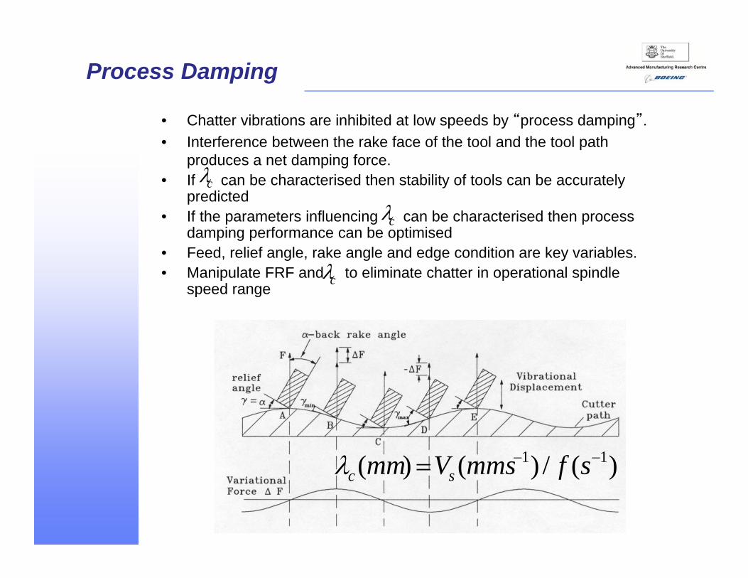
• Chatter vibrations are inhibited at low speeds by “process damping”.• Interference between the rake face of the tool and the tool path
produces a net damping force.• If can be characterised then stability of tools can be accurately
predicted• If the parameters influencing can be characterised then process
damping performance can be optimised• Feed, relief angle, rake angle and edge condition are key variables.• Manipulate FRF and to eliminate chatter in operational spindle
speed range
)(/)()( 11 sfmmsVmm sc
c
c
c
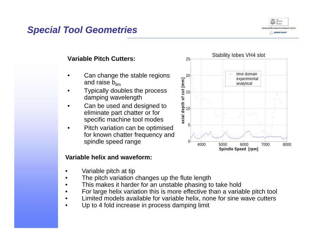
Variable Pitch Cutters:
• Can change the stable regions and raise blim
• Typically doubles the process damping wavelength
• Can be used and designed to eliminate part chatter or for specific machine tool modes
• Pitch variation can be optimised for known chatter frequency and spindle speed range
Special Tool Geometries
Variable helix and waveform:
• Variable pitch at tip• The pitch variation changes up the flute length• This makes it harder for an unstable phasing to take hold• For large helix variation this is more effective than a variable pitch tool• Limited models available for variable helix, none for sine wave cutters• Up to 4 fold increase in process damping limit
4000 5000 6000 7000 80000
5
10
15
20
25
Spindle Speed [rpm]
axia
l dep
th o
f cut
[mm
]
Stability lobes VH4 slot
time domainexperimentalanalytical

• When work holding and machine tool become the constraint given large cuts where tool modes are stabilised
• Determine the system natural freq, this alongside the rpm / number of flutes can give max process damped rpm
• To excite the low frequency structural modes a large impact force must be applied to a point on the structure or the spindle with a suitable accelerometer placed directly opposite.
• Ideally structural shaker testing would be applied tooling at the transition of frequencies
Low Frequency Modes

• Machine dynamics are not the same in static and loaded conditions
• Variable preload on spindles• Change in contact stiffness• Loss of taper contact under large bending moment
• Changing dynamics at high speed / load mean that it is not always possible to use static tool tip tap test measurements to predict cut stability
• Monitoring of the vibrations in the cutting process help us to understand the source of chatter
Non linearity's requiring in process vibration monitoring
Audio method – Harmonizer:

Due to the poor heat dissipation associated with Ti cutting optimum parameters require proportional control of the factors that effect heat generation and dissipation in a process.
Heat generation factors:
•Surface speed (Vs)
•Chip thickness (HEX)
•Arc contact
•Coolant application
•Swarf evacuation
Heat generation and dissipation
High MRR carbide ripper cutters
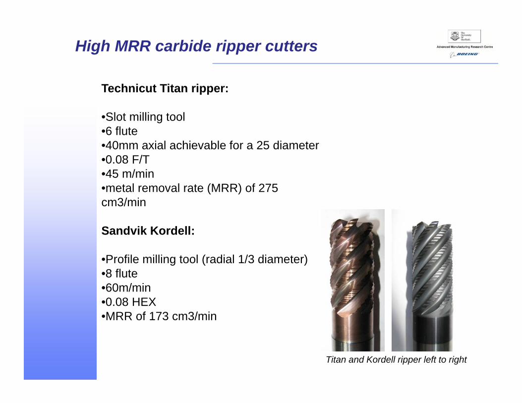
Titan and Kordell ripper left to right
Technicut Titan ripper:
•Slot milling tool •6 flute•40mm axial achievable for a 25 diameter•0.08 F/T •45 m/min •metal removal rate (MRR) of 275 cm3/min
Sandvik Kordell:
•Profile milling tool (radial 1/3 diameter)•8 flute•60m/min •0.08 HEX•MRR of 173 cm3/min

Lobes for 3mm ae Lobes for 19.05mm slot
Corner immersion:
•Increase in wrap around leads to increase in tool wear due to thermal effects
•Increase in radial depth of cut leads to increase in chip thickness requiring feed rate reduction
•Dwell in corner leads to very small feed per tooth work hardening the chip leading to high cutting force and can cause chatter
•Chatter due to increased size of cut limits axial depth of cut for whole process
Tool paths to control tool life and stability

Standard Rad-Corner Pre-Slot
Spiral Trochoidal Outside - in
Tool paths designed to maintain near constant ae in corners:
Flank wear (P2-P4)
00.0010.0020.0030.0040.0050.0060.0070.0080.009
0 5 10 15
no. of pockets
wea
r inc
hes radcorn
standardslotspiralout-in
•Spiral & Rad-corner paths offer practical solutions with ½ the wear of the standard path
•Out-in offers the best solution but this depends upon the stability of the pocket floor

Trochoidal
Complex ramping Spiral morph

level 2 - 0.065f/t – TechnicutTitan finisher
level 3 - 0.065f/t - SandvikPlura
DIA
Finish
Length
Finish
DIA
Rough
Length
Rough
Thin walls
• Maintain An 8/1 L/D Ratio • Avoid harmonic coupling
of symmetric parts and frequency shifts
• Measure cut for tool/part deflection

Controller load = 40% in cut, 52 entry
Controller load = 90% peek
Power monitoring
Given that Ti cutting often occurs at low a low rpm, the power torque curve for the spindle should be consulted to mitigate the risk of spindle stall. The cutter diameter is a key factor effecting entry torque spikes.
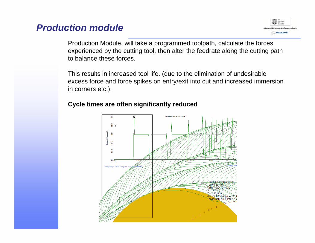
Production moduleProduction Module, will take a programmed toolpath, calculate the forces experienced by the cutting tool, then alter the feedrate along the cutting path to balance these forces.
This results in increased tool life. (due to the elimination of undesirable excess force and force spikes on entry/exit into cut and increased immersion in corners etc.).
Cycle times are often significantly reduced

Roughing tool path - Scallop mill / trochoidal rough to 0.5 off finish, rapid returns applied with 1mm deceleration clearance
Challenge:•Shear key feature required the profile finishing of the form in a single axial pass to eliminate any mismatch.•Overcome instability given the wrap around condition in the corner radii and excessive L/D ratio.
Solution:•A scallop milling approach was taken. •The existing process applied a drilling operation to rough out the corner stock, leaving a work hardened surface preventing optimised finishing methods.
Shear key example - Standard feature

Finishing tool path- Single axial pass with stable finish in corners
Semi finishing tool path -Trochoidal rough corner stock to 0.5 off finish

• Detected with electron beam back scatter diffraction showing damage we would not normally see
• Slip bands in grains and twinning at high speeds >100m/min
• Fatigue initiators
• Texture influences damage, machinability and chip formation
• Damage is sensitive to underlying microstructure
• Slip bands can be generated within the grains- occurrence related to texture
Microstructural damage in Titanium machining

Tool 3 – 86 Minutes in cut – flute A – 2x magnification
Tool 5 – 86 Minutes in cut – flute A – 2x magnification
Dascool 2190 High oil content – Oil emulsion:10%
C
oncentration4%
C
oncentration
Coolant characterisation

Tool 9 – 246 Minutes in cut – flute A – 2x magnification
Tool 8 – 160 Minutes in cut – flute A – 2x magnification
Dascool 2205 Low oil content – Semi-Synthetic:
10%
Concentration
4%
Concentration

Observed tool wear progression for each coolant formulation
0
1
2
3
4
5
0.00 50.00 100.00 150.00 200.00 250.00 300.00Time (min)
Wea
r Mec
hani
sm
Low oil content / 4%ConcentrationLow oil content / 10%ConcentrationHigh oil content / 4%ConcentrationHigh oil content / 10%Concentration
Flank
Crater
Mechanicalfatigue
Edge collapse
Comparative S-Curve Plots:
•A three fold increase in tool life was observed in this experiment
•Final aim is a fundamental understanding of what fluid properties influence the performance of a lubricant in Titanium machining
High performance disk manufacture – Rolls-Royce
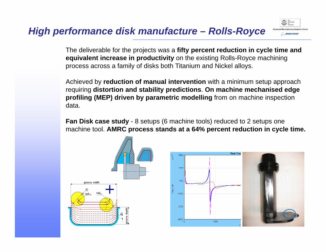
The deliverable for the projects was a fifty percent reduction in cycle time and equivalent increase in productivity on the existing Rolls-Royce machining process across a family of disks both Titanium and Nickel alloys.
Achieved by reduction of manual intervention with a minimum setup approach requiring distortion and stability predictions. On machine mechanised edge profiling (MEP) driven by parametric modelling from on machine inspection data.
Fan Disk case study - 8 setups (6 machine tools) reduced to 2 setups one machine tool. AMRC process stands at a 64% percent reduction in cycle time.

Thank you for listening, any questions?