& installation guide - techno-solis
TRANSCRIPT

Owner’s Manual& Installation GuideOwner’s Manual& Installation Guide
Model 525SModel 525TIModel 650TIModel 650SCModel 700TI

KOPEC Enterprises, Inc., located in Pompano Beach,Florida, designs and manufactures the industry's mostcutting-edge swimming pool heat pumps. We consistentlystrive to provide our customers with the best-made poolheaters at the most competitive prices, and we back it allup with great customer service and continued support.Year after year, KOPEC heat pumps stand up to the ele-ments and have environmental and cost benefits that faroutweigh other heating sources, such as propane gas.KOPEC heat pumps work without fossil fuel dependencyand without environmental pollutants. They also have nosafety concerns.Each of our hand-assembled, hand- tested pumps, meetsexacting specifications and standards. All KOPEC prod-ucts are Safety Certified by Applied ResearchLaboratories and all the performance results are con-firmed by an independent certified test lab.KOPEC offers a large selection of heat pumps for both res-idential and commercial pools and spas. Our pool heatersare used in applications worldwide for houses, condos, hotels, spas andOlympic-sized pools.When it's qualitythat counts, you can count on KOPEC QUALITY.
This product can be very simple to use, but it isimportant to understand the instructions for operation and precautions for installation.Please take a few minutes to read this manual
IndexCompany Introduction ....................................................P - 1General Safety Instructions�.................................��P � 2Unit Installation��........�...........................................P � 2Plumbing���������.......................................P � 3Plumbing Diagrams�����............................��.P � 4-5Electrical Installation��.................................���..P � 6Electrical Diagrams����.................................��.P � 7-9Auto Temp Feature���.......................................��P � 10-11Digital Control Instructions���.................................P � 12Digital Control Electrical Diagrams ............................. .P � 13How to operate your pool heater................................�..P � 14Features and functions (analog models)�.....................P � 15Unit Protection��.................................................��.P � 16Unit Maintenance�.........................................................P � 17Winterizing����..................................................�..P � 17Performance effecting factors��..........................��P � 17-18How does your heat pump heat your pool?.................... P � 19Cooling feature���.....................................................P � 20Troubleshooting����............................................�P � 21-22Hurricane bracket��.............................................��P � 23Warranty�������...............................��� Back CoverRecord keeping and notes��...................��Inside back coverUnit cabinet description����.......................���P � 24
P-1

GENERAL SAFETY INSTRUCTIONSAll electrical installation must be done by a qualified, licensed electrical con-tactor in accordance with all national and local wiring codes.Unit must be bonded to the pool equipment or a 6 ft. copper rod.Once installed, always shut off main power to the unit whenever the accesspanel is opened or removed.
LOCATION- The placement of the pool heater is very important in insuringthe maximum operating efficiency, while keeping installation costs to a mini-mum and allowing access for service and maintenance.The unit is best suited for outdoor installation and should not be installedindoors. If the unit must be installed indoors, adequate air exchange must beprovided to insure efficient unit operation. (Please call the manufacturer fordetails).
CLEARANCE- Please allow 12 inches of clearance from walls, fences, orbushes around the sides and back of your unit, and at least 24 inches in thefront for operation and service access. Allow 4 feet of vertical clearance fromthe top of the unit to the roof overhang. (This will provide quieter operation andwill prevent re-circulation of cold air into the unit, which will effect the unitsheating efficiency).
SPRINKLERS and ROOF RUN OFF- Redirect or cap any sprinklersthat directly hit the unit, and do not install the heater under or near an areawhich will subject it to large amounts of water run off. A gutter or downspoutmay be needed to protect the heater.
SLAB OR BASE THE UNIT SITS ON- Please provide a secure levelsurface at least 36� x 36� for the units base.
UNIT INSTALLATION
RISK OF ELECTRICAL SHOCK OR ELECTROCUTION. The elec-trical supply to this product must be installed by a licensed or certified electri-cian in accordance with the National Electrical Code and applicable localcodes and ordinances. Improper installation will create an electrical hazard, which could result in death or serious injury to pool or spa users,installers, or others due to electrical shock, and may also cause damage toproperty. Read and follow the specific instructions inside the manual.
Drainage- A drain fitting is provided in the bottom of the unit. This fittingallows unit condensation or rainwater to escape, keeping the inside of the unitrelatively dry. Keep the drain fitting clear of leaves or debris to insure properdrainage. You can divert the drain water by attaching a ‰ inch garden hose tothe drain fitting and redirecting it to area better suited for drainage. (Ask yourinstaller).
PLUMBING See page (4 ) Plumbing Diagram
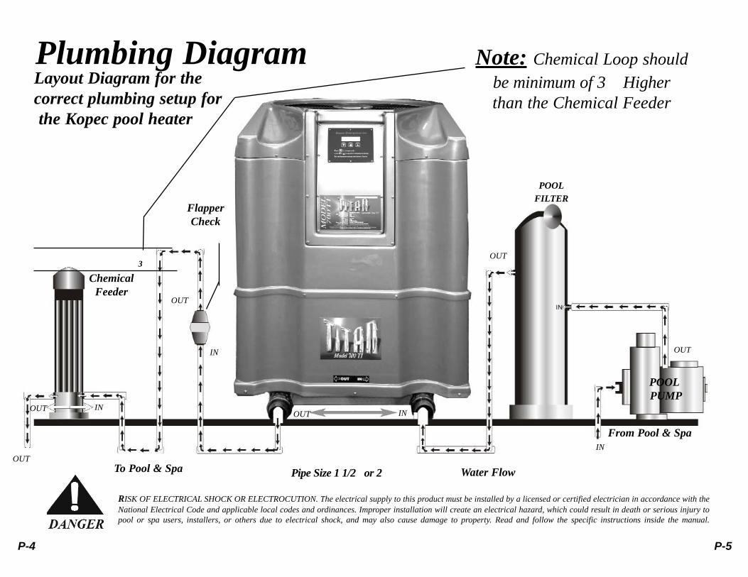
Piping Sequence- Pool- water circulating pump-filter-pool heater- check valve-chlorinator- pool (if a chlorinating devise is used, it must be downstream of theheater, with a check valve installed between it and the heater.) See page 16 onunit protection for more details.
Pipe Connections - Water IN from filter is on the RIGHT. Water OUT to pool ison the LEFT. Normal applications do not require an external bypass. The unitis equipped with 2 inch unions.
Multiple Unit Installations- All plumbing on multiple installations must be inPARALLEL by using an equalized manifold supply pipe. DO NOT install inseries. Visit our web site for more multiple unit plumbing diagrams.
P-2 P-3
RISK OF ELECTRICAL SHOCK OR ELECTROCUTION. The electrical supply to this product must be installed by a licensed or certified electrician in accordance with theNational Electrical Code and applicable local codes and ordinances. Improper installation will create an electrical hazard, which could result in death or serious injury topool or spa users, installers, or others due to electrical shock, and may also cause damage to property. Read and follow the specific instructions inside the manual.
Note: Chemical Loop should be minimum of 3� Higherthan the Chemical Feeder
Plumbing DiagramLayout Diagram for thecorrect plumbing setup for the Kopec pool heater
FlapperCheck
OUT
OUT
OUT
OUT
OUT
OUT
IN
IN
IN
IN
POOLFILTER
POOLPUMP
From Pool & Spa
Water FlowPipe Size 1 1/2�or 2�To Pool & Spa
ChemicalFeeder
3�
P-4 P-5

A qualified, licensed electrician, in accordance with all national and localcode requirements, must perform the electrical installation of your Kopecpool heater.
Standard power supply- 208/240v60hz- 1 Phase. 3 phase units are alsoavailable.
Breaker Size- 50 amp (models 525 ,650 and 700)
Electrical access and installation- The unit is equipped with a 1� inch allthread coupling, which is easily adaptable to rigid or flexible conduit, aswell as junction boxes. Remove access panel to expose electrical controls,then feed main power leads and ground through the units short conduit,allowing a little slack for service purposes. Hook main power leads to thetop of the main contactor. This contactor will have compressor and fanleads already connected to the load or bottom side of the contactor. Hookground wire to the ground lug mounted near the top of the electrical controlpocket.
Unit Bonding- Unit must be bonded to the pool equipment or a 6 ft. copperrod. A bonding lug is provided on the bottom right side of the unit. Failureto bond the unit could damage the units heat exchanger and void the war-ranty.
Flexible Conduit- When codes allow, use flexible conduit at or near theunit for easy service access.
Unit disconnect, breaker orfuse- Per code, a unit dis-connect must be in line ofsight of the unit.
Note- Shut off main powerbefore removing the unitselectrical access panel!
ELECTRICAL
RISK OF ELECTRICAL SHOCK OR ELECTROCUTION. The electrical supply tothis product must be installed by a licensed or certified electrician in accordance with
the National Electrical Code and applicable local codes and ordinances.Improper installation will create an electrical hazard, which could resultin death or serious injury to pool or spa users, installers, or others dueto electrical shock, and may also cause damage to property. Read andfollow the specific instructions inside the manual.
P-6 P-7

Rem ove Jum per for rem otes without therm ostats. W hen using 2 wire rem otes use H&C connections only. Set unit to spa position.
1 2 3 4
5 6 7 8
9 10 11 12
1413CUBERELAY
June 2003
Rem ove Jum per for rem otes with therm ostats. M ake sure pool heaters Therm ostats are at m axim um setting.
RISK OF ELECTRICAL SHOCK OR ELECTROCUTION. The electrical suppplyto this product must be installed by a licensed or certified electrician in accordance with the National Electrical Code and applicable local codes and ordinances. Improper installation will create an electrical hazard, which could result in death or serious injury to pool or spa users, installers, or others due to electrical shock, and may also cause damage to property. Read and follow the specific instructions inside the manual.
!DANGER
P-8 P-9
Remove Jumper for remotes without thermo-stats. When using 2 wire remotes use H&Cconnections only. Set unit to spa position.
Remove Jumper for remotes with thermostats.Make sure Thermostats are at maximum setting.

Auto Temp Feature(pool mode only)
The Auto Temp feature is standard in all Kopec Enterprises, Inc.pool heater models. To activate this feature additional installa-tion by an electrician is required. Electrical installation instruc-tions are on page 11 of this manual. An additional copy of theinstructions for the electrician can be found behind the controlpanel in the component pocket of the heater.
In the Time Clock mode your heater will operate only during thewater circulating pump time clock run period (normally 6-8hours a day depending on pump and pool size). When the timeclock run period ends the pump and heater will turn off and stayoff until the time clock and pump comes on again the next day.During the off period it is common for the Low Water/Troublelight to be on if the water drops below the desired temperaturesetting. This is an indication the unit wants to turn on but willnot until the water pump turns on via the time clock period.
In the Auto Temp mode your heater will override the time clocksetting, turn on the water pump and operate whenever the pooltemperature drops below the desired setting. The heater will beable to run when it needs to anytime day or night which willinsure your desired temperature will be maintained at all times.Auto Temp is a convenient feature for inconsistent swim applica-tions, morning swimming, therapeutic needs and during thecooler months when time clock periods would need to beincreased to maintain desired pool temperatures.
RISK OF ELECTRICAL SHOCK OR ELECTROCUTION. The electrical supply tothis product must be installed by a licensed or certified electrician in accordance withthe National Electrical Code and applicable local codes and ordinances. Improperinstallation will create an electrical hazard, which could result in death or serious injuryto pool or spa users, installers, or others due to electrical shock, and may also causedamage to property. Read and follow the specific instructions inside the manual.
P-10 P-11

* When the unit is powered on the digital controller will display the currentwater temperature flowing through the unit.
* To select pool or spa mode: Press the hand button to select pool or spaposition.
* To adjust water temperature: Press the up and down arrows to change tothe desired water temperature setting.
* There will be a 10 minute time delay before the unit will turn on
* To lock digital control access: Press and hold for 5 seconds the hand but-ton to lock or unlock digital control access.
* To activate �Auto Temp� feature: Pressand hold for 5 seconds the hand button andthe up arrow to enable or disable the AutoTemp feature
* Remote Control: For remote controlinterfacing press and hold the hand buttonand the down arrow to access the remotecontrol menu. Press the up or down arrowto select the desired remote control option.For remotes WITHOUT thermo-stats select the pool/spa option.For remotes WITH thermostatsselect the T-stat option.
!D
AN
GE
R
RISK
OF
ELEC
TRIC
AL S
HO
CK
OR
ELEC
TRO
CU
TIO
N. T
he e
lect
rica
l sup
pply
to th
is p
rodu
ct m
ust b
e in
stal
led
by a
lic
ense
d or
cer
tifie
d el
ectr
icia
n in
acc
orda
nce
with
the
Nat
iona
l El
ectr
ical
Cod
e an
d ap
plic
able
loc
al c
odes
and
or
dina
nces
. Im
prop
er in
stal
latio
n w
ill cr
eate
an
elec
tric
al h
azar
d, w
hich
coul
d re
sult
in d
eath
or s
erio
us in
jury
to p
ool o
r sp
a us
ers,
inst
alle
rs, o
r oth
ers d
ue to
elec
tric
al sh
ock,
and
may
als
o ca
use d
amag
e to
prop
erty
. Rea
d and
follo
w th
e spe
cific
in
stru
ctio
ns in
side
the m
anua
l.
P-12 P-13

HOW TO OPERATE YOUR POOL HEATER( analog models only)
Once the plumbing and electrical installations are complete, you’re nowready to turn on your pool heater. But first, here are some tips before starting
your unit.Water Flow- This is critical to the efficient operation of your unit, (see trou-bleshooting). Make sure your filter is clean and your circulating pump is on before startingyour unit. Also, confirm all plumbing valves are adjusted to allow maximum water flow tothe unit. (DO NOT bypass any water away from unit unless your circlingpump is oversized.)Turn off any waterfalls or fountains to improve heating time.Scroll Compressors- It is not uncommon for units equipped with scroll com-pressors to require 2-3 initial start-up attempts after sitting for extended peri-ods without operating.Time Delay- There is a built in 5-10 minute start-up time delay to protect thecompressor from short cycling under unequilized refrigerant conditions. Dual Thermostats- Your unit is equipped with two thermostats for convenientpool/spa temperature settings.How to set the pool/spa temperature (analog models only) Purchase an inex-pensive floating thermometer and place in your pool. Locate pool thermostatcontrol knob (knob on left) and turn to the maximum setting (clockwise). In 5-10 minutes, the unit will turn on and begin heating. Monitor the temperatureas it increases. Depending on the temperature of the pool at start-up, heat uptime could take as much as 24-48hours. Once the pool has reachedyour desired temperature, slowlyturn the temperature control knobcounter clockwise, (down) until theunit shuts off. The temperature isnow set. Repeat steps for spa tem-perature setting.
Tip- The unit will automatically main-tain your desired temperature, provid-ing your circulating pump is runningvia your pool time clock.Circulating pump operation time mayneed to be increased on the time clock,depending on outside temperatureconditions or desired temperature.
Features and Functions(analog models only)
Pool/Spa switch- This switch, located between the temperature knobs allowsyou to easily switch from pool to spa temperature settings without re-adjustingcontrol knobs.
Tip- When switching from one mode to the other, always turn the plumbingvalves to the correct position. For ex: when in pool thermostat mode, plumb-ing valves need to be adjusted so water is coming from and going to the pool.
Convenient on/off switch- This switch simply turns off the unit, eliminating theneed to turn down the temperature setting or shutting off your breaker.
Tip-This feature should be used only when the unit will be off for extended peri-ods of time, such as vacation or during the summer.
Power On Light- This green light indicates there is power to the unit.
Trouble/Service Light- This red light indicates low or no water flow or a lowvoltage electrical problem. Make sure your filter is clean and your circulatingpump is on. If you have confirmed you have good water flow, call for service.
Tip- In temperatures below 45 degrees, the unit will shut down to protect thecompressor. If this happens, the red light will come on. The unit will startautomatically whentemperature increasesnear 50 degrees andthe red light will goout. Do not call forservice under theseconditions. Allowenough time for the outside temperature toincrease.
P-14 P-15

UNIT PROTECTION
It is your responsibility to maintain the correct chemical balance in your pooland spa water. Improper or inconsistent chemical maintenance could causedamage to your pool/spa equipment, pool surface or lining, pool heater andalso could be harmful to your health. Here are a few tips to avoid these prob-lems.
Install any chlorinating devise down stream of heater with a check valve andplumbing loop between the heater and the chlorinator.DO NOT inject chlorine gas into your pool or spa.DO NOT use floating chlorine tablet feeders.DO NOT put solid chlorine tablets in the skimmer.Maintain a consistent, chemically - balanced pool. Depriving a pool of chemi-cals, then �shocking� it with heavy chemicals is an incorrect and sometimesdamaging practice when performed too often. This is common for homeownerswho are out of town for extended periods of time .
If the heat exchanger in the unit is deprived of water for several days, highchlorine gas could cause excessive corrosion. Even if power to the unit isturned off, be sure that water can still circulate through the unit at all times,especially during the summer months when no heat is required.
Make sure your unit is electrically bonded, as described in the electrical sectionof this manual. This will help prevent electrolysis, which could damage the heatexchanger in your pool heater.
The following are recommended water quality readings. These readings shouldbe maintained at all times to ensure good health while protecting your pool
Note- Damage due to abusive water chemistry or electrolysis is not covered under war-ranty. Please have your water checked regularly by a pool professional.
PH Level 7.2-7.8Total Alkalinity 80-100 PPM (parts per million)Total Dissolved Solids - below 1200 PPMChlorine Concentration (free) 1.0- 2.0 PPM
WINTERIZING YOUR POOL HEATER
During a short term freeze, run your circulating pump continuously to preventdamage to your filter, pump and pool heaters.
During a long-term hard freeze, disconnect the unions on the heater andremove all the water from the heat exchanger to prevent the pipes from burst-ing.
In addition to loosening the unions on the heater, please find the heat exchang-er drain fitting located on the bottom right hand side of the heater. Push in thegray retainer ring while pulling out the gray plug. Once drained simply pushthe plug back into the drain fitting.
Note- Freeze damage is not covered by warranty so please take every precaution duringfreezing conditions.
UNIT MAINTENANCE
Your Kopec pool heater is basically maintenance free!Keep the condensation drain fitting free of any leaves or debris.Hose off any debris that may be in the evaporator fins to ensure good airflow.Clean plastic cabinet occasionally to maintain the bright shiny color
PERFORMANCE EFFECTING FACTORSIt is very important to understand that heat pump pool heaters are designed tomaintain temperature and do not heat quickly. Initial heat up time could be asmuch as 24-48 hours, because it is necessary to heat the concrete walls in thepool, as well as the water. Once your desired temperature is reached, the heatpump will maintain the temperature, providing the circulating pump run time isadequate, depending on temperature desired, size of pool and outside weatherconditions. Listed below are a few factors to consider when evaluating yourunit’s performance.
P-16 P-17

How does your Kopec Heat Pump heat your pool?
A heat pump uses a refrigerant technology to gather heat in the outside air andtransfers it to your pool water. This technology is used because refrigerant canabsorb and transfer heat.
The circulating fan pulls air through the evaporator coil which acts asa heat collector. The very cold liquid refrigerant in the evaporator absorbs thewarmth from the outside air, which in turn changes the state of the refrigerantfrom a liquid to a gas. The refrigerant gas is then pumped into the compressorwhere it is compressed and increases to a very high temperature.
This extremely hot gas then flows into the heat exchanger, where theheat transfer begins. As the cool pool water flows through the heat exchanger,the hot gas gives up its heat,which increases the water temperature. Once therefrigerant gives up its heat, it returns to a liquid state, then passes through anexpansion valve and into the evaporator coil to start the process all over again.
Size of your pool- Most of your heat loss is through the surface area of thepool. The larger the pool, the quicker it will lose temperature.
Wind- Since surface area is the biggest cause of heat loss, the more wind youhave across your pool increases your heat loss even more. Normal wind speedis 2-3 mph.
Water temperature maintained- If you want a higher temperature, you’ll haveto run the unit longer to maintain it. The greater the difference between air tem-perature and water temperature means more heat loss and longer run time.
Pool cover- Covers reduce the surface heat loss and unit run time, which willreduce operational costs and help temperature maintenance in cooler condi-tions.
Outside air temperature- The warmer it is, the easier it is to maintain tempera-ture. The unit has more heat to gather from the air and there is less surface heatloss, which greatly reduces run time and operational costs. The cooler it is, themore heat loss, which increases run time requirement.
Waterfalls, Spillways and Fountains- These features increase heat loss. Shut off features to cut down heat loss andimprove heater’s performance.
P-18 P-19

Cooling Options(analog models only)
TROUBLESHOOTING(analog models only)
The cooling option enables you to cool your pool in the hot summer monthswhen pool water can become too warm and is no longer refreshing. With a spe-cial refrigerant reversing valve along with addition components and wiring thecooling option can be activated with a simple flip of a switch. Depending onyour model the cooling BTU’s will range from 62,000 81,000. The BTU ratingis based on the actual cooling capacity of the compressor in the unit. This rat-ing is different from the heating rating but more than adequate considering ittakes less BTU’s to cool water than it does to heat.
When the pool temperature remains above your desired setting simply switch to�cool� mode on the heater control panel. Your Kopec pool heater will automat-ically cool the pool to the desired temperature setting. For cooler pool waterturn down the pool thermostat knob towards the blue color on the dial.
Note* Cooling option does not operate with the spa thermostat control.Note* Cooling option is not available in models equipped with digital con-trols.
Your Kopec pool heater is very easy to troubleshoot. 60% of service calls arecustomer or installation related. You will be charged for a service call if a serv-ice person is dispatched and there is nothing wrong with your unit. Please takea few minutes to read through this section to avoid these charges before callingfor service. When calling for service, please have your model and serial num-ber available.
Note- unauthorized personnel servicing your unit will void your warranty
Unit not starting. Green power light off- Breaker or fuse may be off. Reset orreplace. If new installation, the unit may be wired wrong by electrician. If theunit still does not run, call for service.
Unit not starting. Green power light on- Unit could be in time delay mode.Wait 5-10 minutes. Remember, do not turn thermostat up and down during thetime delay mode. The time delay will reset and start over every time thermostatis adjusted. Check the temperature setting and the temperature of the pool. Thepool may be at the desired temperature, therefore will not run. If you�re not sureof the water temperature, adjust the thermostat to the maximum setting and wait5-10 minutes. Unit still does not run, call for service.
Unit not starting. Red trouble light on- If outside temperature is below 45degrees, wait until it warms up to at least 50 degrees. Check water flow. Thefollowing causes of low water flow are:
Pump may be off. Adjust time clock so pump will run longer if needed.
Dirty filter or clogged pump basket.
Where applicable, plumbing valves could be turned in the wrong position,which could restrict or prevent water from getting to the heater.
Pool pump could be too small. At least a 1HP pump is suggested for adequatewater flow.
P-20 P-21

Kopec Enterprises HurricaneBracket Instructions
P-23
(6) � Hurricane BracketsPart # KEI-0316
Important!Brackets Must be Installed
Every 12 Inches on the Left and Right Side of the Unit.
* Please NOTE: Installation Instructions in accordance withFlorida Building Code 301.13.1 option #3.
(2) � …� x 1 ‰� Tapcon Concrete Screws with
Gasketed Washers Per Bracket
Drill (2) � 3/16�Pilot Holes 2� Deep
Troubleshooting continued
If new installation, the unit could be piped backwards. Remember, water IN ison the RIGHT and water OUT is on the LEFT.
Note- If your heater is in a pool / spa application, operate the heater in bothpool and spa plumbing modes. If the unit runs in one mode and not the other,then it is likely that the problem is in the plumbing and not the heater.
Unit still not starting, call for service.
Unit is running, but not heating- If cool air is blowing out of the top of theunit, then the unit is heating. Your circulating pump run time may have to beincreased. (See the factors that effect performance section of this manual).
Note- Remember that the unit will not run without water and your circulatingpump time clock controls the amount of time the pump runs. If this is an initialstart up, very cool or high desired temperature condition, you will have toincrease your time clock pump-running period accordingly.If you have considered all operating conditions and reviewed the factors thateffect performance section of this manual, then call for service.
Unit is leaking water- The leak is normal condensation or an internal plumb-ing leak. Shut off unit for at least 2 hours and leave circulating pump on. If leakstops, then it is normal condensation. If the leak continues, call for service.
P-22

P-24
Warranty
06
General Information
Serial #: Model: Date of Purchase:Purchased From:Installed By:
Note: A serial # is required when calling for service. Service will not be performed without a serial #
or proof of date of purchase.
NOTES:
The warranty varies depending on the date of purchase, unit model and the geographic location of
the unit. Please refer to our web-site for a full description of your units warranty coverage.
kopecheatpumps.net
3033-9 NW 25th AvenuePompano Beach, Fl 33069
Phone: 954-917-8998 / Fax: 954-917-8994Toll Free: 866-917-8998
Kopecheatpumps.net

3033-9 NW 25th AvenuePompano Beach, FL 33069
phone: 954-917-8998 / Fax: 954-917-8994Toll Free: 866-917-8998
www.kopecheatpumps.net