ammonium sulphate and co-combustion with peat two...
TRANSCRIPT
-1-
Ammonium Sulphate and Co-Combustion with Peat – Two Strategies to Reduce Gaseous KCl and Chlorine in
Deposits during Biomass Combustion H. Kassman
1,2,*, J. Bowalli
2, J. Pettersson
3, L.-E. Åmand
2
1Vattenfall Power Consultant AB
P.O. Box 1046, SE-611 29 Nyköping, Sweden
2Dep. of Energy and Environment, Division of Energy Technology, Chalmers University of Technology
SE-412 96 Göteborg, Sweden
3Dep. of Chemical and Biological Engineering, Chalmers University of Technology
SE-412 96 Göteborg, Sweden
ABSTRACT Combustion of a biomass with an enhanced content of chlorine (Cl) can result in
operational problems including deposit formation and superheater corrosion. The
strategies to reduce such problems include co-combustion and the use of additives. The
positive effects of such measures are mainly due to sulphation of the alkali chlorides
(KCl for biomass) to less corrosive alkali sulphates or capture of released alkali (K) in
components such as potassium aluminium silicates. A mixture of wood pellets and straw
pellets was fired in a 12 MW circulation fluidised bed (CFB) boiler. PVC was added to
the fuel in order to achieve a further enhanced reference level of gaseous KCl during
certain tests. Two strategies were applied to decrease the risk for superheater corrosion by
reducing gaseous KCl and content of chlorine in deposits. The strategies were sulphation
of KCl by injection of ammonium sulphate and co-combustion with peat. During co-
combustion of biomass with peat both sulphation of KCl and capture of released K in ash
components can be of importance. The results were evaluated by means of several
advanced measurement tools including IACM (on-line measurements of gaseous KCl),
deposit measurements (chemical composition in collected deposits, initial corrosion), ash
analysis (chemical composition in fly ashes). The overall performance was better for
ammonium sulphate, which significantly reduced gaseous KCl. Meanwhile almost no
chlorine was found in the deposits. Only a minor reduction of gaseous KCl was obtained
during co-combustion of biomass with peat although the chlorine content in the deposits
was greatly reduced.
Keywords: Sulphation, Alkali Chlorides, Combustion of biomass, Peat
1. INTRODUCTION Certain biomass fuels, such as straw, contain high amounts of alkali (mainly potassium,
K) and of chlorine (Cl), and low of sulphur (S). Chlorine is during combustion released to
-2-
the gas phase mainly as HCl and KCl. High levels of KCl in the flue gas can cause
enhanced deposit formation and high content of chlorine in deposits causes accelerated
superheater corrosion. Combustion of such biomass fuels in a fluidised bed boiler can
result in various operational problems including bed agglomeration, deposit formation
and superheater corrosion [1, 2]. These operational problems can be mitigated by either
co-combustion or the use of additives. Peat, coal and municipal sewage sludge are among
the fuels suitable for co-combustion with biomass [3-5]. Another possibility to extend the
lifetime of superheater tubes in a boiler is to replace low alloyed steels with more
corrosion resistant materials. Chromia forming austenitic stainless steels, high alloyed
FeCr steels and Ni based superalloys are among the alternative materials when firing
biomass and waste fuels [6].
During co-combustion with peat both sulphation of KCl due to its sulphur content and
capture of released K in ash components can be of importance. Various peat fuels
representing a wide range of ash forming elements have been investigated [3, 7]. The
major ash forming elements were Si, Al, Ca, Fe and S in these investigations. It was
proposed [7] that the positive effects on deposits during co-combustion with peat were
capture of alkali in the gas phase via reactive peat ash. The composition of the reactive
components in the peat ash was not identified since only small amounts of crystalline
phases were detected by XRD. Despite these efforts, the positive effects on deposit
formation and superheater corrosion from peat are not yet fully understood. Al and Si in
peat ashes can capture alkali from KCl by means of formation of alkali alumino silicates.
This formation is also an important during co-combustion with coal. since its ash contains
clay minerals [4], and during addition of clay minerals such as kaolin [8, 9]. The main
constituent of kaolin is kaolinite (Al2Si2O5(OH)4). Reactions between kaolinite and KCl
to form leucite (KAlSi2O6) and kalsilite (KAlSiO4) were presented in [9].
Elemental sulphur or other sulphur/sulphate containing additives can be used for
sulphation of alkali chlorides. The additive reacts with KCl during biomass combustion
and converts it to a less corrosive alkali sulphate. Both homogeneous (gas phase) and
heterogeneous (liquid or solid phase) mechanisms have been proposed for formation of
alkali sulphates from alkali chlorides found in deposits or in ash particles [10]. In
Kassman et al. [11], two sulphur containing additives were evaluated for sulphation of
gaseous KCl: elemental sulphur (S) and ammonium sulphate ((NH4)2SO4). Ammonium
sulphate lowered gaseous KCl and also reduced the chlorine content in the deposits
significantly better than sulphur. Thus the presence of gaseous SO3 was of greater
importance than that of SO2 for sulphation of gaseous KCl [11]. This supported that
sulphation of gaseous KCl takes place according to the reaction formula (R1):
(R1) 2KCl + SO3 + H2O → K2SO4 + 2HCl
The scope of this paper is to demonstrate two strategies to decrease the risk for
superheater corrosion by reducing gaseous KCl and content of chlorine in deposits.
Additionally, results concerning the initial corrosion are presented. The selected
strategies were co-combustion with peat and injection of ammonium sulphate. This
investigation was included in a larger project carried out in a circulating fluidised bed
(CFB) boiler. Results obtained in the same project focusing on co-combustion with
sewage sludge are presented in [5].

-3-
3
oo
7
8
2
1
95
O
O
19
21
10 11 22
12
6
4
13
O
16
O
17
O 20
18
14 15
Figure 1: The 12 MW CFB boiler. 1. furnace; 2. fuel chute; 3. air plenum; 4. primary air; 5. secondary air;
6. fuel feed and sand; 7. cyclone outlet; 8. primary cyclone; 9. particle seal; 10. secondary cyclone; 11: bag
house filter; 12. flue gas fan; 13. IACM; 14. PVC; 15. kaolin; 16. bed material; 17. ammonium sulphate
(AS); 18. Injection of AS; 19-22. measurement positions; 19. before the convection pass; 20. in the
convection pass, 21. after the convection pass; 22. before the stack.
2. MATERIALS AND METHODS
2.1 The boiler and the operating conditions
The 12 MW CFB boiler at Chalmers University of Technology (CTH) shown in Figure 1
was used for the experimental runs. An advantage with it is the possibility to perform
measurement campaigns in a real boiler, while maintaining control over important
operation parameters such as load, air supply and composition of the fuel mix. Alkali
related issues have previously been investigated in the Chalmers boiler in [5, 11-14]. The
combustion chamber has a square cross-section of about 2.25 m2 and a height of 13.6 m.
Fuel is fed from a fuel chute (located at the front of the boiler) to the lower part of the
combustion chamber. The bed
material is recirculated through the
cyclone back to the combustion
chamber, whereas the combustion
gases enter the convection pass where
the gases are cooled down to 150 C
before cleaning in a secondary
cyclone and a bag house filter.
Operating conditions typical for a
CFB boiler were selected (Table 1).
Silica sand (dp=0.3 mm) was used as
bed material.
Tabl 1 . Operating parameters Parameter Average Standard
deviation Load (MW) 6.2 0.2 Fraction of straw pellets, % of load 24 1.0 Be temperature (°C) 851 0.2 Temperature, top of furnace (°C) 869 4 Temperature, cyclone outlet (°C) 822 5 Tem erature, after bag filter (°C) 153 4 Pressure drop in furnace (kPa) 7.4 0.2 Excess air ratio 1.23 0.0 Primary air/total air flow (%) 56 1.0 Fluidisation velocity (m/s) 4.8 0.1
-4-
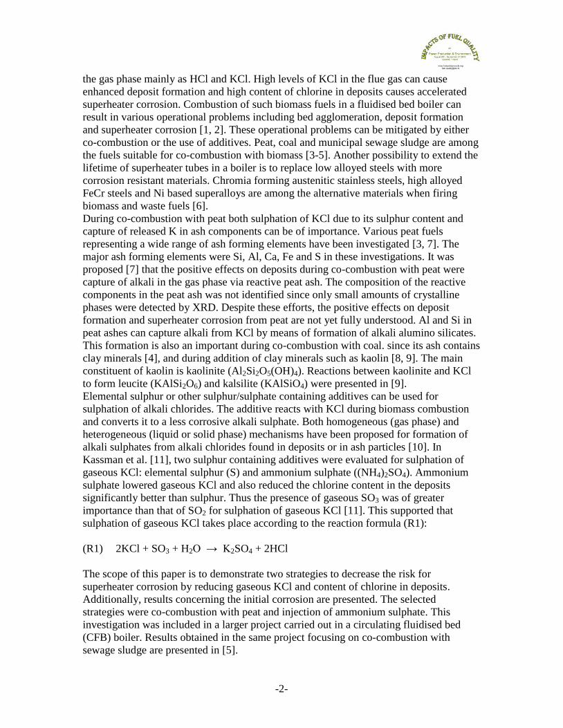
The base fuel was wood pellets
(made from saw-dust of stem
wood of pine and spruce from the
saw mill industry in Sweden).
Straw pellets (made from wheat
straw and manufactured in
Denmark) were used as additional
fuel to increase the level of
gaseous KCl with a constant ratio
of about 25% of the energy input
to the boiler. Co-combustion was
carried out with a mixture of
straw pellets and peat and also
with wood pellets and peat. The
peat selected had low calcium
content. The different fuel
properties are given in Table 2.
The test cases in the test plan are
described below. The reference
case (Ref) was wood pellets with
straw pellets at a constant ratio of
about 25% of the energy input.
During co-combustion of peat
(Peat), a mixture of straw pellets
and peat was used to obtain
similar molar flows of alkali as in
Ref. A flue gas with a further enhanced level of KCl (RefCl) was achieved by adding
polyvinyl chloride (PVC) to (14). Ammonium sulphate (AS, (NH4)2SO4) was added in
the SNCR zone before the primary cyclone (18) under similar conditions as in Ref and
RefCl respectively. These test cases were named AS and ASCl. Hydrated lime was added
before the bag house filter (11) to reduce the emissions of HCl and SO2 during RefCl and
ASCl. Kaolin was added to (14) (molar ratio Al/alkali = 1) to study its effect on bed
agglomeration during AS. Ammonium sulphate is a part of the ChlorOut concept. It
consists of IACM [15], an instrument for on-line measurements of gaseous alkali
chlorides, and a sulphate-containing additive that converts alkali chlorides to less
corrosive alkali sulphates [16]. The additive is often (NH4)2SO4, and, therefore, a
significant NOx reduction is also achieved parallel to the sulphation of alkali chlorides
[13]. Five tests were carried out altogether: Ref, Peat, AS, RefCl, ASCl.
Table 4 presents different experimental parameters for the test cases. These experimental
parameters were discussed in [11]. The molar ratio S/Cl indicates the degree to which a
fuel mix is corrosive and is here given for the total amount of sulphur in fuel and
additive. The risk for corrosion was considered high at a molar ratio S/Cl less than 2.0,
whereas it was low at an S/Cl above 4.0 according to [17]. Peat and AS had the highest
values for S/Cl and Ref and RefCl the lowest ones. Calcium (Ca) in the fuel ash from
biomass is reactive and it also competes with potassium in reacting with sulphur and
chlorine. It was found that the chorine content in the deposits increased at molar ratios of
Table 2 . Fuel properties Wood
pellets Straw pellets
Peat
Proximate analysis Water (wt - %, raw) 8.5 9.5 42 Ash (wt - %, dry) 0.6 5.3 4.1 Combustibles (wt - %, dry) 99.4 94.7 95.9 Volatiles (wt - %, daf) 82 81 70 Ultimate analysis (wt - %, daf) C 50.5 49.3 56.9 H 6.0 6.1 6.1 O 43.4 43.8 34.0 S 0.01 0.08 0.30 N 0.06 0.46 2.71 Cl 0.02 0.27 0.04 Ash analysis (g/kg dry ash) K 138 1 57 3.6 Na 7.5 6.3 1.3 Al 6.7 4.0 77 Si 116 230 150 Fe 8.8 3.4 159 Ca 152 72 93 Mg 30 12 13 P 13 12 12 Ti 0.4 0.3 1.5 Ba 2.2 0.7 1.6 Lower heating value (MJ/kg) H, daf 19.1 18.4 21.9 H, raw 17.1 15.5 11.2 daf = dry and ash free, raw = as rec eived

-5-
S/(Ca+K2+Na2) lower than 0.2 in the fuel [18]. Sulphur is from fuel and additive in the
molar ratios S/(Ca+K2+Na2) and Ca/S in Table 4. The molar ratio Cl/(K+Na) is a
measure of the amount of Cl available in relation to the alkali content of the fuel. It varied
between 0.33 and 0.86 for the present test cases. This implies a lack of Cl to form KCl
even during RefCl. The alkali (Na+K) input load in ranged from 12 to 16 mol/MWh
supplied energy. The sulphur input load varied significantly, which was expected since
most of the sulphur came from the additives. The aluminium (Al) input load is high for
Peat and AS (due to added kaolin) and it is important since Al is involved in alkali
capture reactions.
Table 4. Experimental parameters
Test case Alkalia
mol/MWh
Sulphur
mol/MWh
Al
mol/MWh
S/Cl b S/(Ca+2K+
2Na)b
Cl/(Na+K)b Ca/S
b
Ref 13.9 2.0 0.5 0.38 0.06 0.38 3.3
Peat 13.4 10.2 12.3 1.89 0.24 0.40 1.5
AS 15.8 8.5 16.2 1.65 0.21 0.33 1.0
RefCl 12.4 1.8 0.5 0.17 0.06 0.86 3.6
ASCl 15.9 10.9 0.7 1.05 0.27 0.65 0.8
a = (Na + K), Expressed as mol/MWh, b = molar ratio
2.2 Measurement techniques
A so-called IACM (In-situ Alkali Chloride Monitor) located at (13) was used to measure
the alkali chlorides in the gas phase [15, 19]. It measures the sum of the KCl and NaCl
concentrations on-line but can not distinguish between these two species. The result is
expressed as KCl during biomass combustion. IACM also measures SO2 simultaneously.
Light from a xenon lamp is sent across the furnace or flue gas channel. The light, which
arrives at the receiver, is analysed by a spectrometer. The measurements are made by the
principle of optical absorption. IACM has been used in the present boiler in several
previous projects related to alkali chloride issues [5, 11-14].
Flue gas was also extracted through a heated probe and heated sampling lines to a FTIR
(Fourier Transform Infra-Red) analyser for the determination of HCl, SO2, N2O, NO,
NO2 and NH3 on hot wet flue gases and further to on-line IR-VIS instruments measuring
CO, SO2 and N2O and a paramagnetic analyser for O2 on cold dry gases. A
chemiluminescence analyser was used (in connection to the cold system) for the
measurement of NO. Gas concentrations were measured in a location prior to the
convection pass (19), after the convection pass (21) and before the stack (22).
The deposit measurements were carried out in (19) using temperature controlled deposit
probes. Steel rings were exposed during 4 hours at 500°C and 600°C ring temperature,
respectively. The ring materials in this paper were made of 304L and Sanicro 28, and the
focus during evaluation was on composition of collected deposits and initial corrosion.
The chemical composition of 304L and Sanicro 28 is described in [6]. 304L is an
austenitic stainless steel alloyed with chromium (Cr) and nickel (Ni). Sanicro 28 is a
high-alloyed Fe-based stainless steel with more chromium and nickel compared to 304L.
An important parameter concerning the ability to resist corrosion is the Cr/Fe weight ratio
and it is 0.28 for 304L and 0.77 for Sanicro 28. After exposure, the deposits on the
Sanicro 28 ring (500°C) were analysed by wet chemistry (Inductive Coupled Plasma with

-6-
Optical Emission Spectroscopy ICP-OES and Ion Chromatography IC), whereas deposits
on the 304L ring exposed at 600°C were analysed by means of SEM-EDX (Scanning
Electron Microscopy – Energy Dispersive X-ray) and XRD (X-Ray Diffraction). The
SEM-EDX and XRD analysis were performed on the windward side of the samples
whereas the ICP-OES and IC analysis were made on all of the deposit on the ring.
3. RESULTS
3.1 Concentration in the gas phase
Figure 2 shows transient tests from the starting procedure for the test cases with co-
combustion of peat (Peat) and injection of ammonium sulphate (AS). KCl was measured
by IACM before the convection pass at (19), SO2 and HCl were measured by FTIR
before the stack (22). The transient test for Peat is shown in Figure 2a. KCl was less than
5 ppm during combustion of pure wood pellets (I). Straw pellets were introduced as
additional fuel at t = 20 minutes and as result KCl rose to 40 ppm (II). Co-combustion of
peat started at t = 45 minutes and gaseous KCl decreased to 30 ppm. It was also observed
that SO2 increased to more than 100 ppm and HCl rose to 70 ppm. The increase in HCl
was greater than the decrease in gaseous KCl (III). This indicated that sulphation of KCl
and/or reactions capturing K during the release of HCl had taken place.
0
50
100
150
200
0
10
20
30
40
50
0 25 50 75 100
SO
2, H
Cl p
pm
(a
s m
ea
su
red
)
KC
l pp
m (a
s m
ea
su
red
)
Time (minutes)
III.I. II.
0
50
100
150
200
0
10
20
30
40
50
0 25 50 75 100
SO
2, H
Cl p
pm
(a
s m
ea
su
red
)
KC
l pp
m (a
s m
ea
su
red
)
Time (minutes)
III.II.I.
Figure 2: KCl, SO2 and HCl in transient tests for test cases Peat (a) and AS (b). __ KCl IACM, __ SO2
FTIR, __ HCl FTIR. Peat (a) I. Wood pellets only, II. Supply of straw pellets, III. Peat replaced the wood
pellets. AS (b) I. Wood pellets and straw pellets, II. Injection of 5 l/h ammonium sulphate (S/Cl=1.0), III.
Injection of 10 l/h ammonium sulphate (S/Cl=1.5).
The transient test for AS is shown in Figure 2b. The level of gaseous KCl was 40 ppm
during combustion of wood pellets with 25% straw pellets and addition of kaolin (I).
Ammonium sulphate was injected (S/Cl=1.0) at t = 35 minutes and KCl, SO2, HCl
responded directly (II). The flow of ammonium sulphate was increased to an S/Cl of 1.5
at t = 75 minutes and once more an immediate change in the gas phase concentrations of
KCl, SO2, HCl were observed. Sulphation of KCl in the gas phase according to (R1) is a
fast reaction and the immediate decrease of KCl during injection of ammonium sulphate

-7-
proved a gas phase reaction had occurred. A comparison between the transient tests for
test cases Peat and AS reveals significant differences. Although the concentration of
gaseous SO2 is higher during Peat, the reduction of gaseous KCl is less efficient. This
proves that the sulphur in AS (i.e. SO3) is more efficient for reduction of gaseous KCl
than the sulphur in peat (i.e. SO2). Reactions with ash components capturing released gas
phase KCl would also have decreased KCl during Peat.
Table 4. Gas concentrations (recalculated to ppm dry gas @ 6 % O2)
Test case KCla, ppm SO2
a, ppm HCl
b, ppm NO
c, ppm CO
c, ppm
Ref 44 9 35 86 0
Peat 29 84 83 78 4
AS 7 90 90 23 10
RefCl 109 2 73 73 5
ASCl 15 91 155 12 19
a = measured at (19), b = measured at (21), c = measured at (22).
Results from IACM and gas analysis are
shown in Table 4. The concentration of
HCl increased during Peat compared to
Ref, and during ASCl compared to
RefCl. CO increased somewhat during
test cases AS and ASCl, and a similar
effect has previously been observed [11,
13]. A great reduction of NO was
achieved during injection of ammonium
sulphate. Figure 3 shows the
concentration of KCl and SO2 for test
cases Ref, Peat, RefCl and ASCl. The
measurements were performed before
the convection section (19) where the
temperature of the gas was approximately 800 C. The level of KCl was 44 ppm during
Ref and KCl decreased to 29 ppm during test case Peat. Compared to Ref, only a minor
reduction of gaseous KCl was observed during Peat. The addition of PVC increased KCl
to 109 ppm (RefCl) whereas it dropped to 15 ppm during test case ASCl. The injection of
ammonium sulphate significantly lowered the level of gaseous KCl in the flue gas.
Figure 4: Deposits collected on rings made of 304L at 600°C for test cases Ref, Peat, RefCl and ASCl.
0
25
50
75
100
125
KCl SO2
KC
l, S
O2
(p
pm
dry
ga
s,
6%
O
2)
Ref
Peat
RefCl
ASCl
Figure 3: Concentration of KCl and SO2 for test
cases Ref, Peat, RefCl and ASCl.
Ref Peat
RefCl
ASCl

-8-
3.2 Concentration in deposits and fly ash
Figure 4 shows the deposits collected on rings made of 304L at 600°C for test cases Ref,
Peat, RefCl and ASCl. The colour of the deposits collected during Peat differed from the
other ones, and probably due the presence of ash components originating from Peat.
0
1000
2000
3000
4000
Ref Peat AS RefCl ASCl
De
po
sit
s (
mg
/h*m
2)
Si
P
Mg
Al
Ca
Na
K
Cl
S
0
15
30
45
60
Ref Peat RefCl ASCl
Mo
le %
K Cl SAl
Figure 5: Composition of deposits given as
elements.
Figure 6: Mole % of potassium (K), chlorine (Cl),
sulphur (S) and aluminium (Al) in the deposits
Figure 5 shows the composition in
deposits collected from the whole ring
analysed by ICP-OES and IC. During
Ref the deposits consisted mainly of K
and Cl. The chlorine content was much
lower during Peat compared to Ref. The
reduction of Cl was achieved although
the content of sulphur was still low. This
indicated that the chlorine was reduced
by capture of K during the release of Cl
as HCl rather than sulphation. The
highest chlorine content was present
during RefCl. Nevertheless no chlorine
was found in the deposits during ASCl,
when ammonium sulphate was injected
at a molar ratio S/Cl of 1. Figure 6 shows the mole % of K, Cl, S and Al for test cases
Ref, Peat, RefCl and ASCl. The deposit consisted mainly of KCl during RefCl, which
was fully sulphated during ASCl. It was observed that the deposit contained more
aluminium during Peat, which could possibly be explained by capture of K in a potassium
aluminium silicate. Figure 7 shows the chemical composition in fly ashes from the
secondary cyclone. There was no chlorine present in the ashes from AS and ASCl. The
ash from Peat had an enhanced content of Fe and Al compared to Ref and both of these
elements can have an impact on the deposit chemistry for Peat. Evaluation of XRD
analysis of the fly ash from Peat is complicated due to the interference from amorphous
components. There is, nevertheless, an indication of the presence of iron oxides and
silicates.
0%
20%
40%
60%
80%
100%
Ref Peat AS RefCl ASCl
Co
nte
nt
(wt
%)
Si
P
Ba
Mn
Ti
Fe
Mg
Al
Ca
Na
K
Cl
S
Figure 7: Chemical composition in weight % for fly
ash (sec. cyclone)
-9-
3.3 Gaseous KCl and chlorine in deposits
Injection of ammonium sulphate significantly lowered gaseous KCl and almost no
chlorine was found in the deposits. It was possible to reduce completely reduce chlorine
at a molar ratio S/Cl of 1. Sulphation of gaseous KCl was less important during the co-
combustion with peat, but the chlorine content in the deposits was, nevertheless, greatly
reduced (S/Cl = 1.9). This could possibly be explained by sulphation or capture of K on
reactive ash components followed by the release of HCl when using peat. It is indicated
that chlorine was reduced in the deposits by capture of K rather than sulphation.
3.3 Initial corrosion
The corrosion front during test cases Ref, Peat and ASCl was investigated by means of
SEM-EDX analysis. The deposit layer was mechanically removed from rings made 304L
exposed at 600°C for 4 hours.
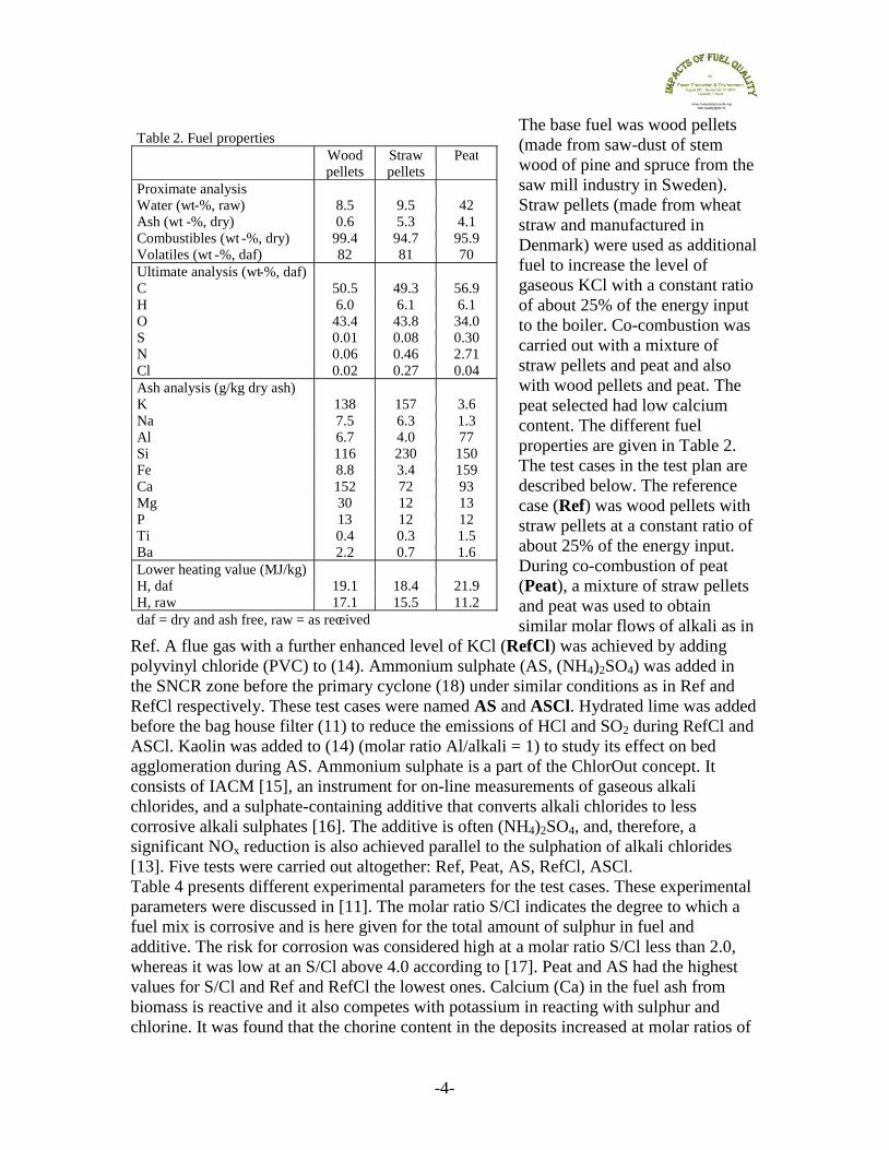
Figure 8: EDX maps of the area beneath the deposit layer on 304L at 600°C during Ref.
Table 5. EDX quantifying of element composition in the points shown in Figure 8.
(a%) O K Na Mg Ca Al P S Cl Si Fe Cr Ni
1 55 14 1 0 1 0 0 9 2 1 8 9 0
2 17 1 1 0 0 0 0 1 1 0 60 8 11
3 60 1 0 0 0 0 0 0 13 0 22 1 3
Figure 8 shows that although most of the deposit layer was removed, some areas are still
covered by deposit particles. According to the EDX analysis, these areas are rich in K and
Cl indicating the presence of KCl (which also was detected by XRD). In addition, areas
containing K, S and O (probably K2SO4) are detected. However, there are some areas
enriched in Cl indicating the presence of deposit particles. Near point analysis #3, the
chlorine content is around 13% whereas the potassium content is low. Instead, the EDX
quantification indicates the presence of transition metal chloride, probably FeCl2. There
are a number of spots enriched in chromium, in the vicinity to point analysis #1. These
areas correlate with potassium, indicating the presence of potassium chromate (K2CrO4).
3 2
1

-10-
The EDX quantification in point #2 shows an area covered with an oxide. This oxide is
depleted in chromium and is instead dominated by iron.
Figure 9: EDX maps of the area beneath the deposit layer on 304L exposed at 600°C during Peat.
Table 6. EDX quantifying of element composition in the points shown in Figure 9.
(a%) O K Na Mg Ca Al P S Cl Si Fe Cr Ni
1 0 1 0 0 0 0 0 0 0 2 72 15 10
2 37 21 2 2 4 6 1 11 0 2 13 2 0
The EDX analysis of the ring from the exposure during test case Peat is shown in Figure
9 and Table 6. The SEM image reveals an area where the deposit layer is partly removed.
In the middle of the image, the underlying steel can be seen as Fe, Cr and Ni can be
correlated whereas the occurrence of elements eminating from deposit particles is low.
The deposit layer is dominated by K, S and O. However, Al, Ca and Si appears
sporadically within this layer. According to the EDX quantification, the Al content is 6%
(point #2). The chlorine content is below the detection limit of EDX analysis, all over the
surface. Spots enriched in chromium can be found within the deposit layer. These spots
also contain manganese (not showed), indicating the presence of a Cr-Mn spinel oxide.
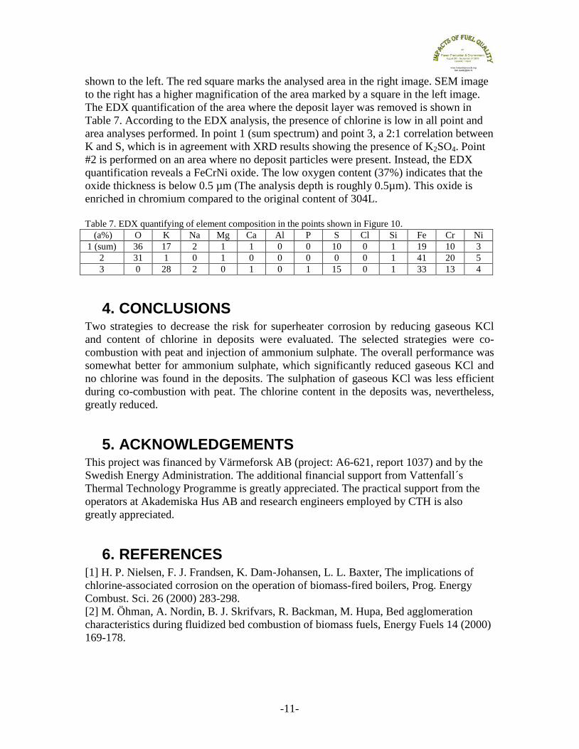
Figure 10: SEM images of the 304L sample exposed for 4 hours at 600°C in test case ASCl.
The 304L sample exposed at 600°C for 4 hours in the exposure for ASCl is shown in
Figure 10. An overview image of the surface after mechanically removed deposit layer is
Deposit present
Mechanically
removed
deposit
-11-
shown to the left. The red square marks the analysed area in the right image. SEM image
to the right has a higher magnification of the area marked by a square in the left image.
The EDX quantification of the area where the deposit layer was removed is shown in
Table 7. According to the EDX analysis, the presence of chlorine is low in all point and
area analyses performed. In point 1 (sum spectrum) and point 3, a 2:1 correlation between
K and S, which is in agreement with XRD results showing the presence of K2SO4. Point
#2 is performed on an area where no deposit particles were present. Instead, the EDX
quantification reveals a FeCrNi oxide. The low oxygen content (37%) indicates that the
oxide thickness is below 0.5 µm (The analysis depth is roughly 0.5µm). This oxide is
enriched in chromium compared to the original content of 304L.
Table 7. EDX quantifying of element composition in the points shown in Figure 10.
(a%) O K Na Mg Ca Al P S Cl Si Fe Cr Ni
1 (sum) 36 17 2 1 1 0 0 10 0 1 19 10 3
2 31 1 0 1 0 0 0 0 0 1 41 20 5
3 0 28 2 0 1 0 1 15 0 1 33 13 4
4. CONCLUSIONS Two strategies to decrease the risk for superheater corrosion by reducing gaseous KCl
and content of chlorine in deposits were evaluated. The selected strategies were co-
combustion with peat and injection of ammonium sulphate. The overall performance was
somewhat better for ammonium sulphate, which significantly reduced gaseous KCl and
no chlorine was found in the deposits. The sulphation of gaseous KCl was less efficient
during co-combustion with peat. The chlorine content in the deposits was, nevertheless,
greatly reduced.
5. ACKNOWLEDGEMENTS This project was financed by Värmeforsk AB (project: A6-621, report 1037) and by the
Swedish Energy Administration. The additional financial support from Vattenfall´s
Thermal Technology Programme is greatly appreciated. The practical support from the
operators at Akademiska Hus AB and research engineers employed by CTH is also
greatly appreciated.
6. REFERENCES [1] H. P. Nielsen, F. J. Frandsen, K. Dam-Johansen, L. L. Baxter, The implications of
chlorine-associated corrosion on the operation of biomass-fired boilers, Prog. Energy
Combust. Sci. 26 (2000) 283-298.
[2] M. Öhman, A. Nordin, B. J. Skrifvars, R. Backman, M. Hupa, Bed agglomeration
characteristics during fluidized bed combustion of biomass fuels, Energy Fuels 14 (2000)
169-178.

-12-
[3] K. Lundholm, A. Nordin, M. Öhman, D. Boström, Reduced Bed Agglomeration by
Co-combustion Biomass with Peat Fuels in a Fluidized Bed, Energy Fuels 19 (2005)
2273-2278.
[4] M. Aho, E. Ferrer, Importance of coal ash composition in protecting the boiler against
chlorine deposition during combustion of chlorine-rich biomass, Fuel 84 (2005) 201-212.
[5] A. L. Elled, K. O. Davidsson, L.-E. Åmand, Sewage sludge as a deposit inhibitor
when co-fired with high potassium fuels, Biomass Bioenergy (2010),
doi:10.1016/j.biombioe.2010.05.003.
[6] J. Pettersson, Alkali Induced High Temperature Corrosion of Stainless Steel -
Experiences from Laboratory and Field, in: Department of Chemical and Biological
Engineering, Ph. D., Chalmers University of Technology, 2008.
[7] L. Pommer, M. Öhman, D. Boström, J. Burvall, R. Backman, I. Olofsson, A. Nordin,
Mechanisms Behind the Positive Effects on Bed Agglomeration and Deposit Formation
Combusting Forest Residue with Peat Additives in Fluidized Beds, Energy Fuels 23
(2009) 4245-4253.
[8] M. Öhman, A. Nordin, The role of kaolin in prevention of bed agglomeration during
fluidized bed combustion of biomass fuels, Energy Fuels 14 (2000) 618-624.
[9] B. M. Steenari, O. Lindqvist, High-temperature reactions of straw ash and the anti-
sintering additives kaolin and dolomite, Biomass Bioenergy 14 (1998) 67-76.
[10] P. Glarborg, Hidden interactions - Trace species governing combustion and
emissions, Proceedings of the Combustion Institute 31 (2007) 77-98.
[11] H. Kassman, L. Bäfver, L. E. Åmand, The importance of SO2 and SO3 for sulphation
of gaseous KCl – An experimental investigation in a biomass fired CFB boiler, Combust.
Flame 157 (2010) 1649-1657.
[12] H. Kassman, C. Andersson, J. Högberg, L. E. Åmand, K. Davidsson, Gas phase
alkali chlorides and deposits during Co-combustion of coal and biomass, 19th
International Conference on Fluidized Bed Combustion, Vienna, Austria, 2006.
[13] H. Kassman, M. Holmgren, E. Edvardsson, L. E. Åmand, J. Öhlin, Nitrogen
containing additives for simultaneous reduction of KCl and NOx during biomass
combustion in a CFB boiler, 9th
Int Conf on Circulating Fluidized Beds, Hamburg,
Germany, 2008.
[14] K. O. Davidsson, L. E. Åmand, B. M. Steenari, A. L. Elled, D. Eskilsson, B.
Leckner, Countermeasures against alkali-related problems during combustion of biomass
in a circulating fluidized bed boiler, Chem. Eng. Sci. 63 (2008) 5314-5329.
[15] European Patent EP 1221036 (2006).
[16] European Patent EP 1354167 (2006).
[17] K. Salmenoja, Field and laboratory studies on chlorine-induced superheater
corrosion in boilers fired with biofuels, Department of Chemical Engineering, PhD
Thesis, Åbo Akademi University, 2000.
[18] P. Yrjas, B. J. Skrifvars, M. Hupa, J. Roppo, M. Nylund, P. Vainikka, Chlorine in
deposits during co-firing of biomass, peat, and coal in a full-scale CFBC boiler, Proc of
the 18th
Int Conf on Fluidized Bed Combustion, Toronto, Canada, 2005, pp. 679-687.
[19] C. Forsberg, M. Broström, R. Backman, E. Edvardsson, S. Badiei, M. Berg, H.
Kassman, Principle, calibration, and application of the in situ alkali chloride monitor,
Rev. Sci. Instrum. 80 (2009).