ametek precitech, inc. - industrial equipment auctions ... prior consent of ametek® precitech, inc....
TRANSCRIPT

Super Turn Series Manual Supplement to
Nanoform 700 Ultra Ultra Precision Machining System
M17958 Revision D April 29, 2010 Applies to Nanoform 700 Ultra A17700
These original instructions have been drafted and verified in the English language.
AMETEK® Precitech, Inc. 44 Blackbrook Road
Keene, New Hampshire 03431 Tel: (603) 357-2511, Fax: (603) 358-6174
All rights reserved, including those to reproduce this manual or parts thereof in any form without the prior consent of AMETEK
® Precitech, Inc.

Customer Service Department
Tel: 603-357-2511 Fax: 603-358-6174
General E-mail: [email protected]
Mike Wilson e-mail: [email protected]
Field Service Supervisor
Jenn Johnson e-mail: [email protected]
Sales Support Manager
Tom Spiltoir e-mail: [email protected]
Service Engineer - Metrology
Chuck Currier e-mail: [email protected]
Service Engineer
Chuck Durgin e-mail: [email protected]
Service Engineer
Kevin Maxwell e-mail: [email protected]
Service Engineer
Curt Mead e-mail: [email protected]
Service Engineer
Ken Lefebvre e-mail: [email protected]
Service Engineer
Revision History
Rev Date ECO Revision Pages First Used By
B
C 04/06/10
None Add language statement 04/06/10
?
D 04/29/10
None Updated P-Tables to P915 Status 04/29/10
DAJ
TABLE OF CONTENTS
SECTION 1 Machine Safety............................................................................... 1 Warning Labels................................................................................................. 3 Residual Risks .................................................................................................. 5 Electrical Hazards............................................................................................. 7 Machine Safety Interlocks ................................................................................ 9 Operator Actuated Safety Controls................................................................. 10 Operator Guards Operation, Testing, and Maintenance................................. 11 Permission/Password Matrix .......................................................................... 11 Nanoform 700 Ultra Noise Emissions............................................................ 12 Release of Person Trapped in or by Machine................................................. 13 Safety System Response Time ....................................................................... 14
SECTION 2 Fixture Mounting ......................................................................... 15 SECTION 3 On-Machine Probe Linearity/Repeatability Calibration Procedure............................................................................................................................ 19 SECTION 4 Setup & Calibration of the Horizontal Tool Set Probe................ 27 SECTION 5 Setup & Calibration of the Vertical LVDT Tool Set Probe ........ 37 SECTION 6 Setup & Calibration of the Part Surface Probe ............................ 40 SECTION 7 Bar Code Scanner Operation........................................................ 55 SECTION 8 Machining & Inspection Process Sequence................................. 58 SECTION 9 Tool Change Process.................................................................... 69 SECTION 10 Program File Printouts ............................................................... 81 SECTION 11 P Variable Assignments ........................................................... 102
N700 Super Turn Series Manual Machine Safety
M17958 - Revision D 1
SECTION 1
Machine Safety
N700 Super Turn Series Manual Machine Safety
M17958 - Revision D 2
Read the Manuals! The Operation and Maintenance manuals describe the proper procedures for the safe interactions with the machine. Failure to read the manuals may lead to machine damage and/or operator injury.
Lock Out-Tag Out - The placement of all hazardous energy under the exclusive control of an authorized employee(s) performing the service or maintenance, following a procedure established by the employer as required by OSHA 29 CFR 1910.147, Isolation of Energy Sources-Machinery Safety Directive 89/392EEC the Control of Hazardous Energy.
Note that the sliding operator door uses power to unlock. If the door is closed when power is removed, it is locked. If access is required without applying power, basic screwdrivers can release the door, but the machine controller will not recognize the door being latched and closed until the bypass function is deactivated.
The Main Electrical Disconnect Switch - on the front of the machine allows a lock to be inserted in the handle when the switch is in the OFF position. This ensures that the Electrical System of the Machine is in a condition where it can be safely serviced.
This Machine is equipped with an accessory receptacle located behind the swinging cover at back corner of the machine. This receptacle is fed from a separate power source in addition to the Machine Main Feed. In order to fully (secure) LOCK OUT-TAG OUT this receptacle, the plug for the source conductor must be pulled and covered with a lockable shell (boot) made expressly for this purpose.
The Pneumatic Supply Lockout Valve - is located at the rear of the machine and is clearly labeled. This lockable valve, also vents the machine air supply. Removing and venting upstream air supply will not vent the machine air.
N700 Super Turn Series Manual Machine Safety
M17958 - Revision D 3
Warning Labels
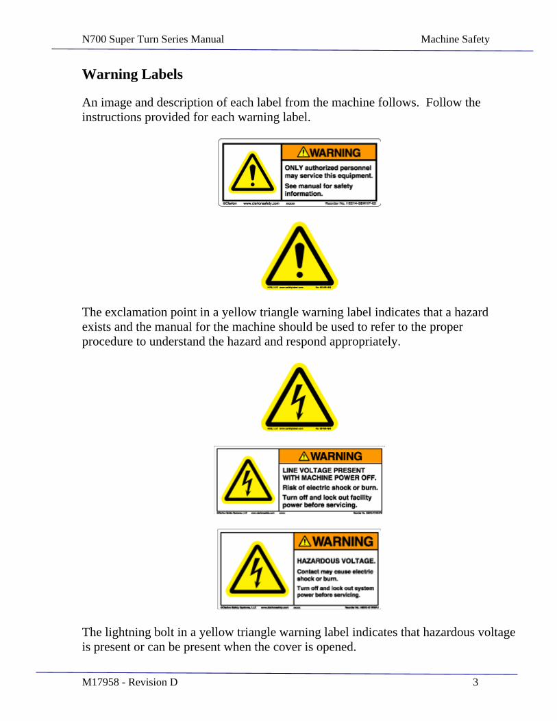
An image and description of each label from the machine follows. Follow the instructions provided for each warning label.
The exclamation point in a yellow triangle warning label indicates that a hazard exists and the manual for the machine should be used to refer to the proper procedure to understand the hazard and respond appropriately.
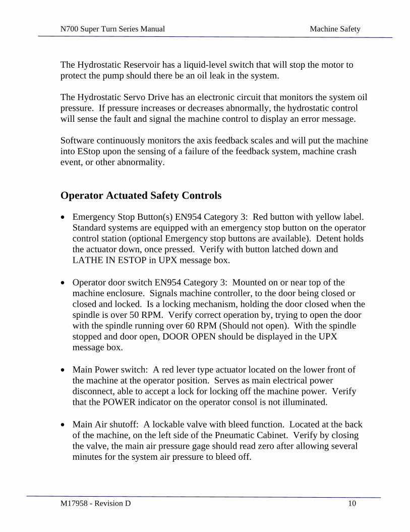
The lightning bolt in a yellow triangle warning label indicates that hazardous voltage is present or can be present when the cover is opened.
N700 Super Turn Series Manual Machine Safety
M17958 - Revision D 4
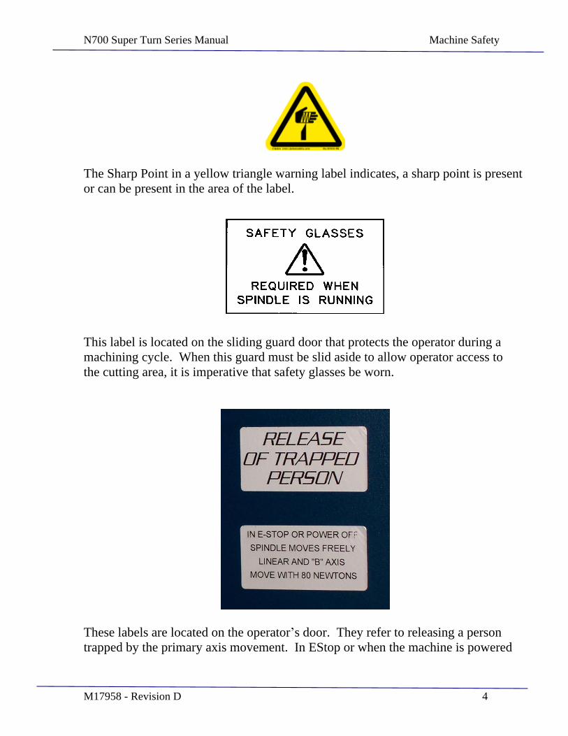
The Sharp Point in a yellow triangle warning label indicates, a sharp point is present or can be present in the area of the label.
This label is located on the sliding guard door that protects the operator during a machining cycle. When this guard must be slid aside to allow operator access to the cutting area, it is imperative that safety glasses be worn.
These labels are located on the operator s door. They refer to releasing a person trapped by the primary axis movement. In EStop or when the machine is powered
N700 Super Turn Series Manual Machine Safety
M17958 - Revision D 5
down, axes brakes and friction can be manually overcome in there normal direction of travel.
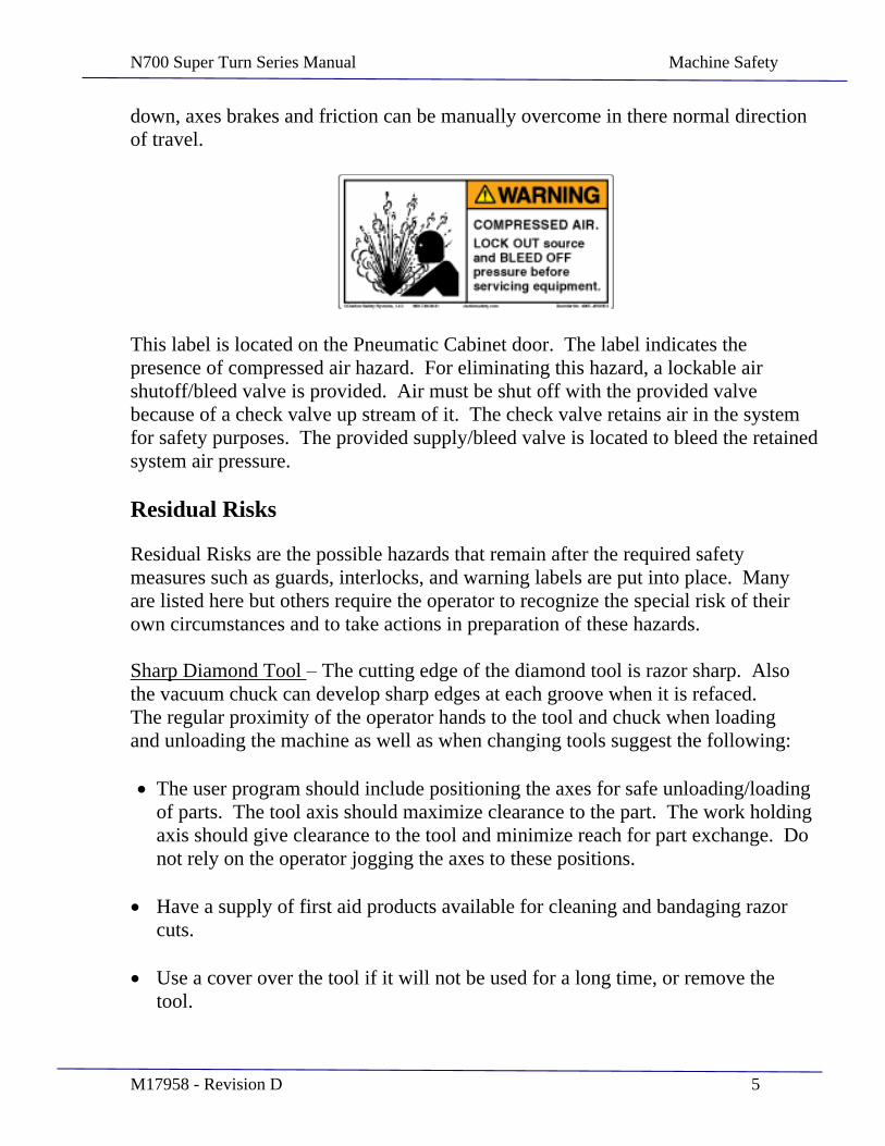
This label is located on the Pneumatic Cabinet door. The label indicates the presence of compressed air hazard. For eliminating this hazard, a lockable air shutoff/bleed valve is provided. Air must be shut off with the provided valve because of a check valve up stream of it. The check valve retains air in the system for safety purposes. The provided supply/bleed valve is located to bleed the retained system air pressure.
Residual Risks
Residual Risks are the possible hazards that remain after the required safety measures such as guards, interlocks, and warning labels are put into place. Many are listed here but others require the operator to recognize the special risk of their own circumstances and to take actions in preparation of these hazards.
Sharp Diamond Tool The cutting edge of the diamond tool is razor sharp. Also the vacuum chuck can develop sharp edges at each groove when it is refaced. The regular proximity of the operator hands to the tool and chuck when loading and unloading the machine as well as when changing tools suggest the following:
The user program should include positioning the axes for safe unloading/loading of parts. The tool axis should maximize clearance to the part. The work holding axis should give clearance to the tool and minimize reach for part exchange. Do not rely on the operator jogging the axes to these positions.
Have a supply of first aid products available for cleaning and bandaging razor cuts.
Use a cover over the tool if it will not be used for a long time, or remove the tool.

N700 Super Turn Series Manual Machine Safety
M17958 - Revision D 6
Consider special operator training on proper use and handling of diamond tool products.
Wear Safety Glasses - Operators and maintenance personnel must wear safety glasses whenever the Precitech spindle is running and the operator door is open. It is good practice to wear safety glasses around the machine at all times.
Wear Leather Gloves Operators and Maintenance personnel must wear leather gloves when handling chips and swarf.
Wear a Dust Mask - The diamond-turning process may produce swarf or chips that float in the air. A protective mask must be worn over the operator s nose and mouth to prevent inhaling or ingesting substances that may be toxic.
Dress Properly - Do not operate the PRECITECH Machining System while wearing jewelry, loose fitting clothing, neckties, shirtsleeves, or unprotected long hair.
Stay Alert - Do not operate the PRECITECH Machining System while under the influence of medication, drugs, or alcohol.
Use the Dowel Pin in the Vacuum Chuck The dowel pin in the center of the vacuum chuck provides initial alignment of the fixture to the spindle, and improves safety as the part will not fly off if severely unbalanced.
Use Maximum Available Vacuum Diameter Set the vacuum diameter of the vacuum chuck to utilize the entire fixture face available. Use of a smaller diameter limits the vacuum holding force, which increases the risk that the part will fall off the vacuum chuck.
Modification to the part holding fixture- Removing material from, or adding parts to the fixture may reduce the maximum safe speed and or create hazards. Mark any modified fixtures with new maximum safe speed.
Lift Safely - Do not lift objects that are uncomfortable or back strain may occur. Use a crane for heavy components.
Avoid Tripping or Slipping Hazards Keep the machine area clear of hoses and wires that present tripping hazards. Be aware of liquids on the floor, clean up oil spills and repair leaks immediately to prevent slipping injuries.

N700 Super Turn Series Manual Machine Safety
M17958 - Revision D 7
Safety Guards Must Be In Place - Operators must be sure that all guards are in place while the PRECITECH Machining System is running to protect against bodily injury.
Maintain the Machine Properly - Do not operate this machining system when it is in need of repair or service. Proper maintenance will help avoid machine downtime, loss of production and injury to personnel.
Do Not Disable Machine Safety Interlocks - Many safety features have been built into the Machining System and should not be disabled. Special applications and service may require temporary interlock override, please consult with Precitech.
Material Safety Data Sheet (MSDS) -
PRECITECH provides MSDS for products recommended for use on the machine. Persons likely to come in contact with these materials should be familiar with the information contained in the sheets such as:
o Product identification o First aid procedures o Personal protective measures o Health hazards o Spill procedures
Lockout Tagout -
Follow your companies LOCK OUT-TAG-OUT procedure when servicing the machine to prevent starting or energizing the machine. Lock main power, machine mounted air supply valve and accessory power sources.
Note that the operator door uses power to unlock. If the door is closed when power is removed it will remain locked until power is restored. If access is required to the working zone during repairs, do not close the operator sliding door. There is a bypass key to allow access for servicing. This key is provided with the machine and should be kept by the maintenance personnel responsible for servicing the machine.
Electrical Hazards
Power is supplied to this machine through multiple sources and power removal for servicing also has multiple levels.
With the main disconnect switched off, primary power is removed from most of the machine. Power remains at the supply side of the main power switch, at the
N700 Super Turn Series Manual Machine Safety
M17958 - Revision D 8
accessory outlet, and other machine elements with separate cords such as the spindle chiller.
EStop Power is removed from the spindle motors and slide motors. Position feedback elements, the control computer, and the hydraulic power supply unit remain powered.
Key Switch Off Power is removed from the machine control, hydraulic power unit, axis and spindle drives. Power remains in the electrical cabinet.
Air pressure remains on.
Electrical/Electronic Troubleshooting - Must be performed by personnel trained to troubleshoot electrical circuits. An electrical hazard exists when personnel exceed the limitations of their training.
Hydraulic/Pneumatic Repair - Do not attempt to repair or service pneumatic or hydraulic components while the Precitech Machining System is connected to the pneumatic or hydraulic power sources or if either system remains under pressure.
N700 Super Turn Series Manual Machine Safety
M17958 - Revision D 9
Machine Safety Interlocks
Precitech Machining Systems are designed with mechanical, electrical, and pneumatic components whose use is dedicated to protecting the operator and the machine.
All Cabinet Doors and Service Access Panels have tool-operated latches or fasteners to prevent casual entry.
The Electrical Cabinet is mechanically interlocked to prevent exposure to lethal voltage.
The Air Accumulator Tank contains an adequate volume of air to allow the machine spindle to stop safely should the air supply be interrupted. A check valve prevents back flow from the accumulator tank should the supply hose be disconnected. A relief valve releases air from the accumulator tank if the supply pressure exceeds 11.72 bar (170 psig). An air pressure switch located in the pneumatic cabinet monitors the regulated air pressure. If that pressure falls below 5.2 bar (95 psig), the Control will sense the fault, dynamically brake the spindle, disable the spindle drive, and display an error message.
A Vacuum Switch is located in the pneumatic cabinet that monitors the work-holding chuck vacuum. If that vacuum falls below 15" Hg (38 cmHg), the control will sense the fault, dynamically brake the spindle, disable the spindle drive, and display an error message.
N700 Super Turn Series Manual Machine Safety
M17958 - Revision D 10
The Hydrostatic Reservoir has a liquid-level switch that will stop the motor to protect the pump should there be an oil leak in the system.
The Hydrostatic Servo Drive has an electronic circuit that monitors the system oil pressure. If pressure increases or decreases abnormally, the hydrostatic control will sense the fault and signal the machine control to display an error message.
Software continuously monitors the axis feedback scales and will put the machine into EStop upon the sensing of a failure of the feedback system, machine crash event, or other abnormality.
Operator Actuated Safety Controls
Emergency Stop Button(s) EN954 Category 3: Red button with yellow label. Standard systems are equipped with an emergency stop button on the operator control station (optional Emergency stop buttons are available). Detent holds the actuator down, once pressed. Verify with button latched down and LATHE IN ESTOP in UPX message box.
Operator door switch EN954 Category 3: Mounted on or near top of the machine enclosure. Signals machine controller, to the door being closed or closed and locked. Is a locking mechanism, holding the door closed when the spindle is over 50 RPM. Verify correct operation by, trying to open the door with the spindle running over 60 RPM (Should not open). With the spindle stopped and door open, DOOR OPEN should be displayed in the UPX message box.
Main Power switch: A red lever type actuator located on the lower front of the machine at the operator position. Serves as main electrical power disconnect, able to accept a lock for locking off the machine power. Verify that the POWER indicator on the operator consol is not illuminated.
Main Air shutoff: A lockable valve with bleed function. Located at the back of the machine, on the left side of the Pneumatic Cabinet. Verify by closing the valve, the main air pressure gage should read zero after allowing several minutes for the system air pressure to bleed off.

N700 Super Turn Series Manual Machine Safety
M17958 - Revision D 11
Stop Button, EN954 Category 3: Red rectangular illuminated momentary. Stops the part program or other motion when in progress. Does not stop the spindle when in spindle mode. To stop the spindle, in spindle mode, call up the direct command input (MDI) dialog box and type M5, then press enter then press start. Verify by starting a part program, then press stop. The program and the axes should stop.
Operator Guards Operation, Testing, and Maintenance
The sliding operator door is the main safety device keeping the operator safe from machining hazards. These hazards include entanglement in the work spindle rotation, exposure to the cutting fluid or cutting chips of possibly hazardous materials, and possible flying tools, parts of tools, work pieces, or parts of work pieces. The operator is safe if the door is closed, and exposed if the door is open.
To maintain operator safety, the sliding operator door is provided with a switch and electrical lock. There are also operator password access levels that allow different levels of access to the work zone. The door lock and access allowed are summarized as follows:
Permission/Password Matrix
Standard (CE) Super Turn (CE)
Door Open Door Closed Door Open Door Closed Key switch on, password level 0
Indications: Door open Machining Mode
No powered movement, program edit or program load.
Indications: Machining Mode
Run MDI Run program Jog axes Run spindle to rated speed (via MDI or program). No program edit or load.
Indications: Door open Machining Mode
No power movement. No program edit, run or load.
Indications: Machining Mode
Run program. No program edit or load. No jog or MDI.
Key switch on, password level 1
Indications: Door open Setting Mode
Jog axes to 1 m/min, 50 RPM. Run MDI. Load program, no edit.
Indications: Machining Mode
Jog axes. Run MDI or Program. Load program, no edit. Set cutting tool.
Key switch on, password level 2
Indications: Door open Setting Mode
Indications: Machining Mode
Run MDI, program, jog
Indications: Door open Setting Mode
Indications: Machining Mode
Jog axes.

N700 Super Turn Series Manual Machine Safety
M17958 - Revision D 12
Axes jog to 1 m/min, 50 RPM. Edit or load program. No velocity controlled spindle.
axes Run spindle to rated speed (via MDI or program). Edit or load program.
Axes jog to 1 m/min, 50 RPM. Run MDI. No program edit, run or load.
Run MDI or Program. No program edit or load. No setting of cutting tool.
Key switch on, password level 3
Indications: Door open Maintenance Mode
Hold to run and MDI allowed. Run spindle to 50RPM (via MDI or program). Edit or load or run program. Machine setup parameters accessible
Indications: Machining Mode
Hold to run and MDI allowed. Run spindle to rated speed (via MDI or program) Program edit or load.
Same as standard Same as standard
Testing the proper function of the guard interlocks can be done by attempting to perform each interlocked function and notice the machine response to each combination of inputs. For example, open the operator sliding door with the machine not in EStop and rotate the work spindle by hand to exceed 50 RPM. The machine should go into EStop condition automatically.
Test proper operation of the vacuum interlock by mounting a small piece of paper on the vacuum fixture (held only by vacuum), run the spindle at 45 rpm. Switch the vacuum to off. Paper should stay on fixture. Now remove the paper, turn the vacuum on high. A low vacuum warning should be displayed on the UPX and the spindle should not start.
The window in the operator guard has been selected to provide operator safety as well as to provide good long term durability to chemicals and cleaning solutions. It is made of 0.25 inch thick laminated safety glass, with glass layers on both sides and a layer of vinyl in the center. The glass layers provide good chemical resistance and long term clarity. The vinyl layer in the center maintains the window in one piece even when the glass layer has been broken. If an accident occurs and the window is cracked or broken then it must be replaced to maintain the proper level of operator safety. If the vinyl layer has become discolored this is a sign that there may be de-lamination of the layers and the window should be replaced. Replacement windows are available from Precitech (or see the service section of the manual for part number identification) and are replaced using standard hand tools.
Nanoform 700 Ultra Noise Emissions
With no access to an anechoic chamber, an "in situ" airborne noise emission test was conducted on the Nanoform 700 Ultra located on the Precitech assembly floor. The sound power level never exceeded 65 dB as measured in each of the

N700 Super Turn Series Manual Machine Safety
M17958 - Revision D 13
following locations and conditions: front, left side, rear, right side, machine off, machine on, spindle stopped, spindle running, guard door closed, guard door open.
Test was performed with an Extech 407706 Sound Level Meter set at the 60 dB scale, "Slow" response, "A" weighting. The meter was mounted on a Velbon Victory 451 tripod. All measurements were made at 1 meter from the machine and 1.5 meters off the floor (as prescribed by Kris Swanson / Swanson Safety Associates).
Per EN292-2 this noise emission data is to be accompanied by the following statement:
The figures quoted are emission levels and are not necessarily safe working levels. Whilst there is a correlation between the emission and exposure levels, this cannot be used reliably to determine whether or not further precautions are required. Factors that influence the actual level of exposure of the workforce include the characteristics of the work room, the other sources of noise, etc. i.e. the number of machines and other adjacent processes. Also the permissible exposure level can vary from country to country. This information, however, will enable the user of the machine to make a better evaluation of the hazard and risk.
Release of Person Trapped in or by Machine
In the unlikely situation where a person or object has become trapped or captured by the machine, this is most probably due to motion of the Z and X slideways or the work spindle rotation. The machine is expected to be in EStop as a result of this condition, either initiated by the operator or by the machine controller. In this situation, the X and Z slideways can be pushed by hand to move the slides so that the trapped object is freed. The force to overcome the slide brake is approximately 20 pounds of force (90 Newtons) and is easily produced by a single assistant or by the trapped person directly. The spindle rotation is not braked and can be turned by hand to free the trapped entanglement. These manual interventions will not affect the machine performance and a routine re-homing of the slides will have the machine back up and running. Any injury to the object or person trapped will depend upon where on the machine the entrapment occurred.
N700 Super Turn Series Manual Machine Safety
M17958 - Revision D 14
Safety System Response Time
When an emergency stop is initiated, power to the axes and spindles is removed in 140 milliseconds. Time for the main spindle to come to a stop is 7.5 seconds with no fixture or part mounted. Deceleration time will increase with the addition of fixturing and a part.
A controlled stop takes 11 seconds with no fixture or part mounted. Deceleration time will increase with the addition fixturing and a part. The door remains locked until the spindle is at or below 50 RPM.
N700 Super Turn Series Manual Fixture Mounting
M17958 - Revision D 15
SECTION 2
Fixture Mounting
N700 Super Turn Series Manual Fixture Mounting
M17958 - Revision D 16
Safety: Refer to section 1 for operator safety warnings.
Wear Safety Glasses
Wear Protective Gloves
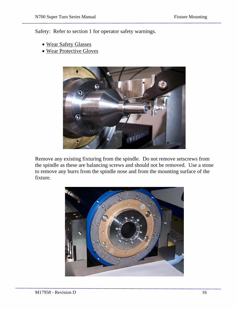
Remove any existing fixturing from the spindle. Do not remove setscrews from the spindle as these are balancing screws and should not be removed. Use a stone to remove any burrs from the spindle nose and from the mounting surface of the fixture.
N700 Super Turn Series Manual Fixture Mounting
M17958 - Revision D 17
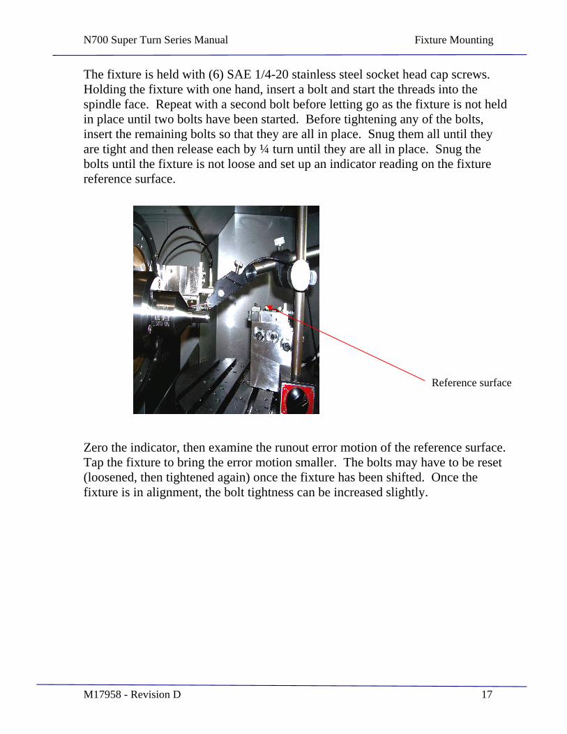
The fixture is held with (6) SAE 1/4-20 stainless steel socket head cap screws. Holding the fixture with one hand, insert a bolt and start the threads into the spindle face. Repeat with a second bolt before letting go as the fixture is not held in place until two bolts have been started. Before tightening any of the bolts, insert the remaining bolts so that they are all in place. Snug them all until they are tight and then release each by ¼ turn until they are all in place. Snug the bolts until the fixture is not loose and set up an indicator reading on the fixture reference surface.
Zero the indicator, then examine the runout error motion of the reference surface. Tap the fixture to bring the error motion smaller. The bolts may have to be reset (loosened, then tightened again) once the fixture has been shifted. Once the fixture is in alignment, the bolt tightness can be increased slightly.
Reference surface
N700 Super Turn Series Manual Fixture Mounting
M17958 - Revision D 18
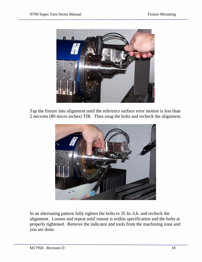
Tap the fixture into alignment until the reference surface error motion is less than 2 microns (80 micro inches) TIR. Then snug the bolts and recheck the alignment.
In an alternating pattern fully tighten the bolts to 35 In.-Lb. and recheck the alignment. Loosen and repeat until runout is within specification and the bolts at properly tightened. Remove the indicator and tools from the machining zone and you are done.
N700 Super Turn Series Manual Probe Linearity/Repeatbility Calibration Procedure
M17958 - Revision D 19
SECTION 3
On-Machine Probe Linearity/Repeatability Calibration Procedure
N700 Super Turn Series Manual Probe Linearity/Repeatbility Calibration Procedure
M17958 - Revision D 20
This Procedure is to perform linear calibration and check linearity and repeatability of +/- 1mm mechanical LVDT linear displacement probes connected to the 4 channel IGA board in a UPX controller.
If adjustments are made here, other calibration procedures will be necessary. Repeatability is most important to the on machine metrology functions. Verifying repeatability will give a good indication of probe and system condition, and might be used to initiate further action.
Safety: Keep clear of moving machine elements. Personnel performing this procedure should be properly trained in electrical safety.
Avoid collisions of machine elements and probes!
Tools Required:
Non conductive potentiometer adjustment tool
Shim stock, 0.5mm thick. Approximately 5mm x 30mm. Edges should be flat and smooth.
Probe adjustment spanner, not normally needed (Precitech PN 168-0087).
Probes: A13883 spring extend and A17868 vacuum retract Integrated Gage Amplifier: A17924
Probe Description UPX display / labels Part Surface Probe Probe F / SURF Horizontal Tool Probe Probe C / H.P. Vertical Tool Probe Probe D / V.P.
Clean the probes and the surfaces to be probed.
Surface Probe
1. Move the Z axis to the right hand end of travel, to provide clearance to rotate the B axis.
2. Rotate the B axis to align the probe body with the Z axis direction of travel (+/- 1 degree). The ruby tip should be toward the spindle. Be sure not to wind up the coolant line and probe cable.
N700 Super Turn Series Manual Probe Linearity/Repeatbility Calibration Procedure
M17958 - Revision D 21
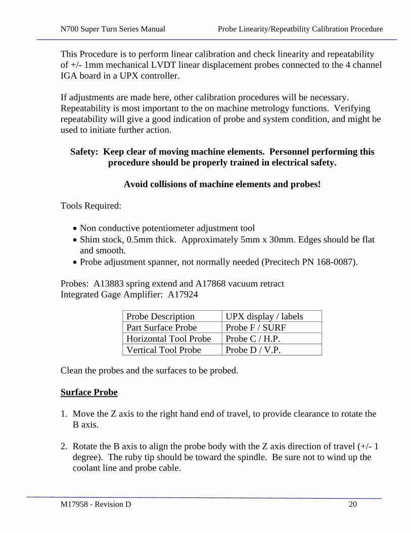
3. On the machine control touch screen, select the Setup mode, then Servo Monitor and Tools, then 4 Channel Gage Amp.
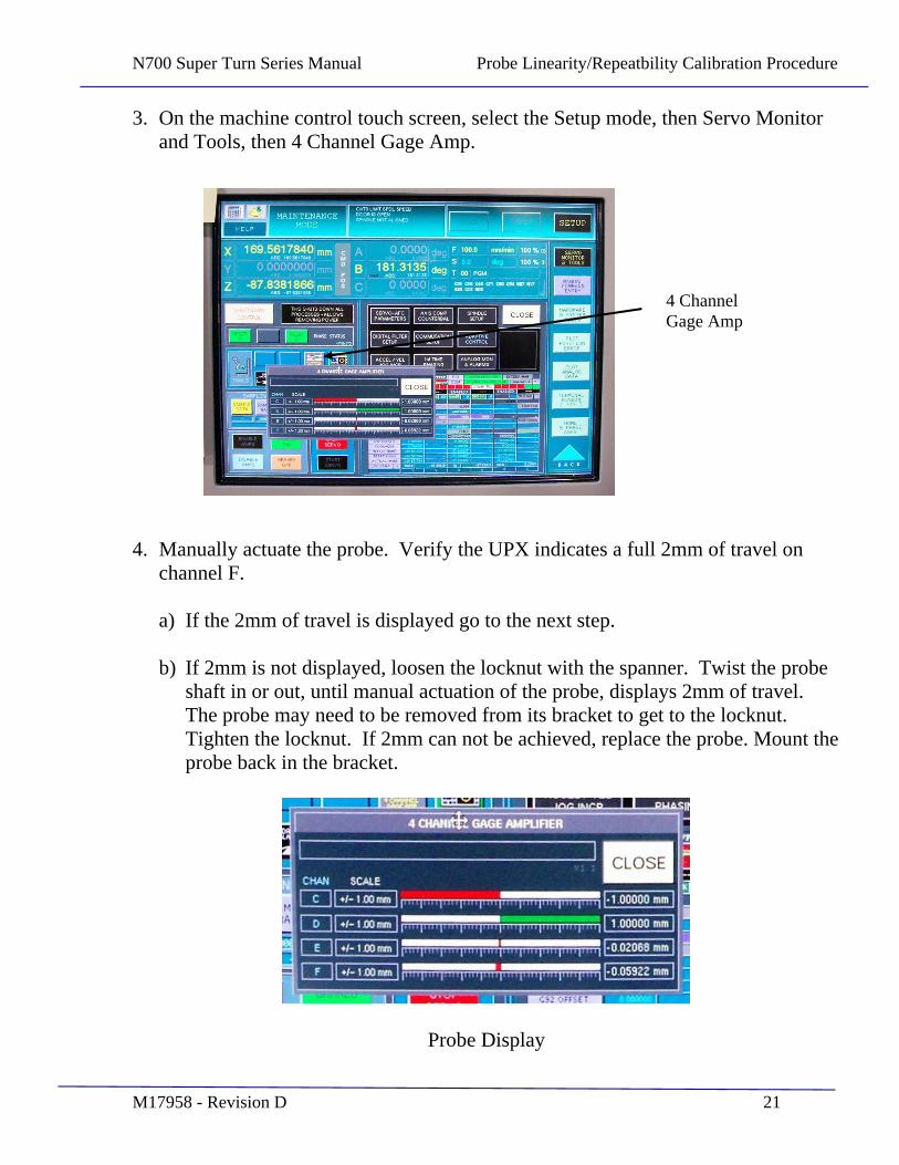
4. Manually actuate the probe. Verify the UPX indicates a full 2mm of travel on channel F.
a) If the 2mm of travel is displayed go to the next step.
b) If 2mm is not displayed, loosen the locknut with the spanner. Twist the probe shaft in or out, until manual actuation of the probe, displays 2mm of travel. The probe may need to be removed from its bracket to get to the locknut. Tighten the locknut. If 2mm can not be achieved, replace the probe. Mount the probe back in the bracket.
Probe Display
4 Channel Gage Amp
N700 Super Turn Series Manual Probe Linearity/Repeatbility Calibration Procedure
M17958 - Revision D 22
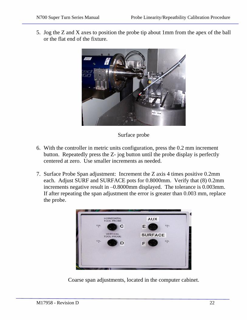
5. Jog the Z and X axes to position the probe tip about 1mm from the apex of the ball or the flat end of the fixture.
Surface probe
6. With the controller in metric units configuration, press the 0.2 mm increment button. Repeatedly press the Z- jog button until the probe display is perfectly centered at zero. Use smaller increments as needed.
7. Surface Probe Span adjustment: Increment the Z axis 4 times positive 0.2mm each. Adjust SURF and SURFACE pots for 0.8000mm. Verify that (8) 0.2mm increments negative result in 0.8000mm displayed. The tolerance is 0.003mm. If after repeating the span adjustment the error is greater than 0.003 mm, replace the probe.
Coarse span adjustments, located in the computer cabinet.
N700 Super Turn Series Manual Probe Linearity/Repeatbility Calibration Procedure
M17958 - Revision D 23
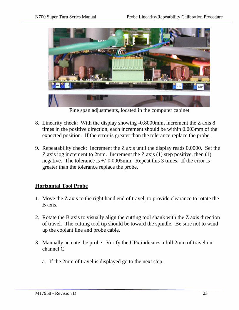
Fine span adjustments, located in the computer cabinet
8. Linearity check: With the display showing -0.8000mm, increment the Z axis 8 times in the positive direction, each increment should be within 0.003mm of the expected position. If the error is greater than the tolerance replace the probe.
9. Repeatability check: Increment the Z axis until the display reads 0.0000. Set the Z axis jog increment to 2mm. Increment the Z axis (1) step positive, then (1) negative. The tolerance is +/-0.0005mm. Repeat this 3 times. If the error is greater than the tolerance replace the probe.
Horizontal Tool Probe
1. Move the Z axis to the right hand end of travel, to provide clearance to rotate the B axis.
2. Rotate the B axis to visually align the cutting tool shank with the Z axis direction of travel. The cutting tool tip should be toward the spindle. Be sure not to wind up the coolant line and probe cable.
3. Manually actuate the probe. Verify the UPx indicates a full 2mm of travel on channel C.
a. If the 2mm of travel is displayed go to the next step.
N700 Super Turn Series Manual Probe Linearity/Repeatbility Calibration Procedure
M17958 - Revision D 24
b. If 2mm is not displayed, loosen the locknut with the spanner. Twist the probe shaft in or out, until manual actuation of the probe, displays 2mm of travel. The probe may need to be removed from its bracket to get to the locknut. Tighten the locknut. If 2mm can not be achieved, replace the probe. Mount the probe back in the bracket.
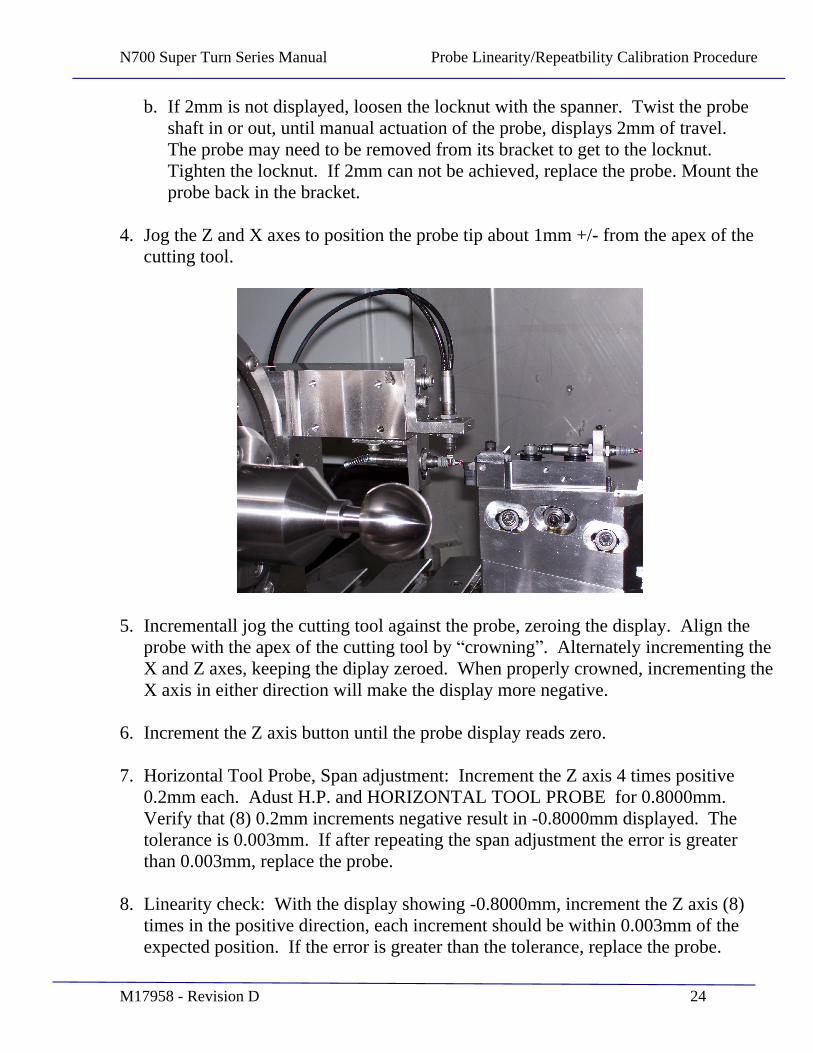
4. Jog the Z and X axes to position the probe tip about 1mm +/- from the apex of the cutting tool.
5. Incrementall jog the cutting tool against the probe, zeroing the display. Align the probe with the apex of the cutting tool by crowning . Alternately incrementing the X and Z axes, keeping the diplay zeroed. When properly crowned, incrementing the X axis in either direction will make the display more negative.
6. Increment the Z axis button until the probe display reads zero.
7. Horizontal Tool Probe, Span adjustment: Increment the Z axis 4 times positive 0.2mm each. Adust H.P. and HORIZONTAL TOOL PROBE for 0.8000mm. Verify that (8) 0.2mm increments negative result in -0.8000mm displayed. The tolerance is 0.003mm. If after repeating the span adjustment the error is greater than 0.003mm, replace the probe.
8. Linearity check: With the display showing -0.8000mm, increment the Z axis (8) times in the positive direction, each increment should be within 0.003mm of the expected position. If the error is greater than the tolerance, replace the probe.
N700 Super Turn Series Manual Probe Linearity/Repeatbility Calibration Procedure
M17958 - Revision D 25
9. Repeatability check: Increment the Z axis until the display reads 0.000. Set the Z axis jog increment to 2mm. Increment the Z axis (1) step positive, then (1) negative. The tolerance is +/-0.0005mm. Repeat this (3) times. If the error is greater than the tolerance, replace the probe.
Vertical Tool Probe
1. Open the Manual Command Enter (MDI ) window. Type: M17, press enter then start. This should extend the probe.
2. Manually actuate the vertical probe, checking that the D display indicates a full 2mm of travel.
a. If the 2mm of travel is displayed go to the next step.
b. If 2mm is not displayed, loosen the locknut with the spanner. Twist the probe shaft in or out, until manual actuation of the probe, displays 2mm of travel. The probe may need to be removed from its bracket to get to the locknut. Tighten the locknut. If 2mm can not be achieved, replace the probe. Mount the probe back in the bracket.
3. Open the Manual Command Enter (MDI ) window. Type: M18, press enter then press start. This should retract the probe.
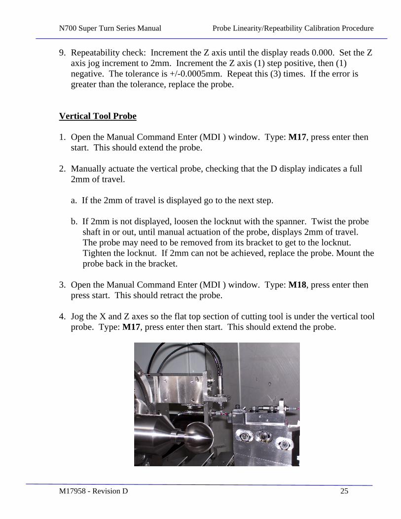
4. Jog the X and Z axes so the flat top section of cutting tool is under the vertical tool probe. Type: M17, press enter then start. This should extend the probe.
N700 Super Turn Series Manual Probe Linearity/Repeatbility Calibration Procedure
M17958 - Revision D 26
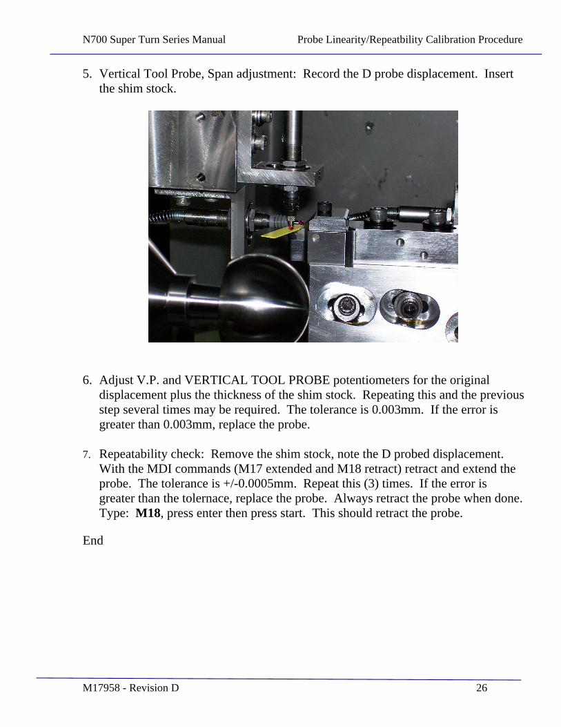
5. Vertical Tool Probe, Span adjustment: Record the D probe displacement. Insert the shim stock.
6. Adjust V.P. and VERTICAL TOOL PROBE potentiometers for the original displacement plus the thickness of the shim stock. Repeating this and the previous step several times may be required. The tolerance is 0.003mm. If the error is greater than 0.003mm, replace the probe.
7. Repeatability check: Remove the shim stock, note the D probed displacement. With the MDI commands (M17 extended and M18 retract) retract and extend the probe. The tolerance is +/-0.0005mm. Repeat this (3) times. If the error is greater than the tolernace, replace the probe. Always retract the probe when done. Type: M18, press enter then press start. This should retract the probe.
End
N700 Super Turn Series Manual Setup & Calibration of the Horizontal Tool Set Probe
M17958 - Revision D 27
SECTION 4
Setup & Calibration of the Horizontal Tool Set Probe

N700 Super Turn Series Manual Setup & Calibration of the Horizontal Tool Set Probe
M17958 - Revision D 28
LVDT Probe Overview
The Precitech Super Turn Series lathe configuration utilizes three LVDT probes for the purpose of implementing four different measurements. One probe is used as a vertical tool setting device, providing the operator the ability to precisely set the height of the tool relative to spindle centerline. A second probe also related to tool setting, is mounted in the horizontal plane parallel to the spindle. It is used to determine the tool radius, and tool location relative to the B axis centerline. A third probe serves as dual functionality, and is used as a surface probe to determine the precise location of the part in the Z direction before machining, as well as a measurement probe to precisely evaluate the part geometry following machining. The results can be then used to make periodic corrections for upcoming part machining.
The primary reference point for the entire system is the horizontal toolset probe, and specifically is the center of the probe tip ball. (Not the apex of the ball). The cutting tool and the surface/measurement probe are both referenced to this point. This allows the location and radius size of each to be stored in the UPx control tool table, which provides a convenient means to manage the respective offsets to one to the other. When a tool bit is replaced the new tool parameters are then stored in the Tool Table, and a known relationship to the surface/measurement probe is maintained. Selection of each device then becomes a matter of selecting the desired tool number. The tool number assignments in the case of the Super Turning Series machining process are fixed. The cutting tool is always Tool #1. The surface/measurement probe is Tool #8 when it is in a parallel (0 degree) orientation to spindle centerline, and is Tool #9 when it is in the perpendicular (90 degree) orientation to spindle centerline.
N700 Super Turn Series Manual Setup & Calibration of the Horizontal Tool Set Probe
M17958 - Revision D 29
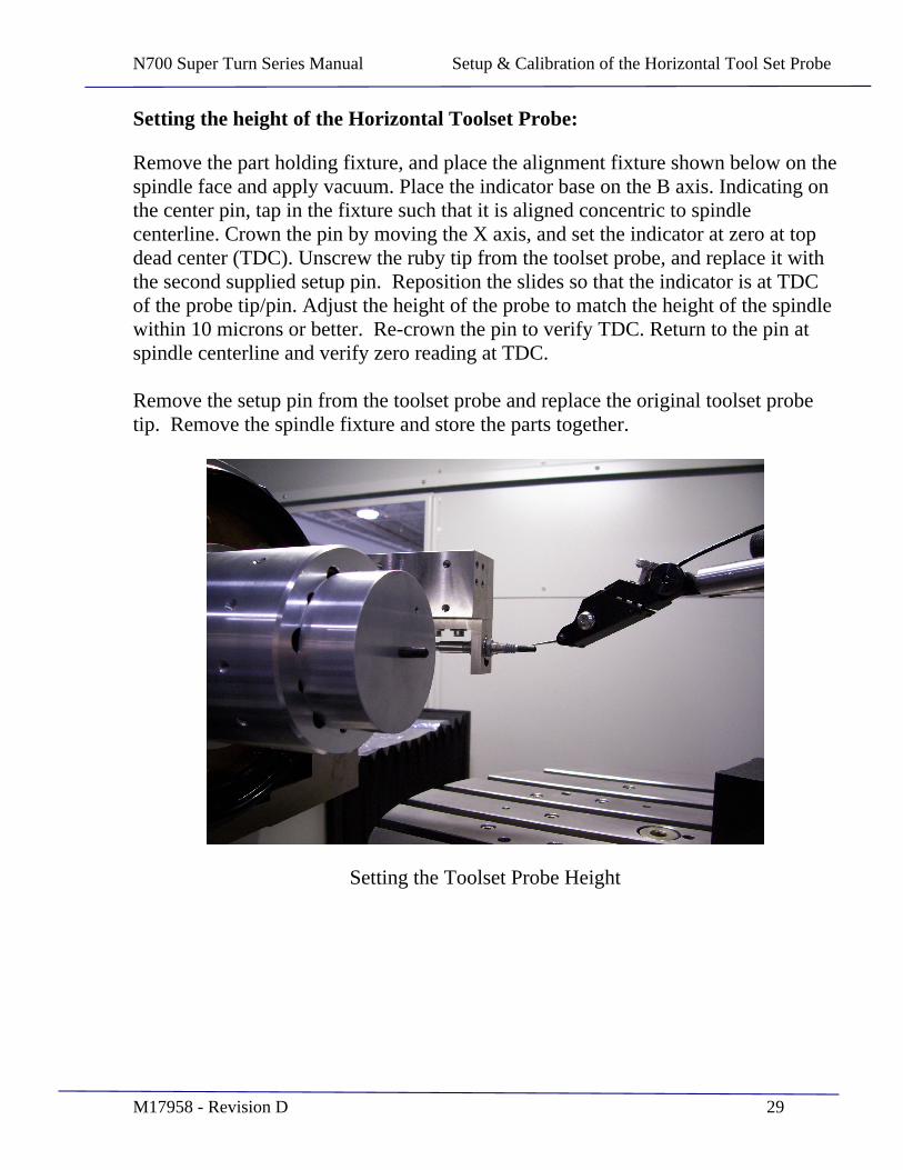
Setting the height of the Horizontal Toolset Probe:
Remove the part holding fixture, and place the alignment fixture shown below on the spindle face and apply vacuum. Place the indicator base on the B axis. Indicating on the center pin, tap in the fixture such that it is aligned concentric to spindle centerline. Crown the pin by moving the X axis, and set the indicator at zero at top dead center (TDC). Unscrew the ruby tip from the toolset probe, and replace it with the second supplied setup pin. Reposition the slides so that the indicator is at TDC of the probe tip/pin. Adjust the height of the probe to match the height of the spindle within 10 microns or better. Re-crown the pin to verify TDC. Return to the pin at spindle centerline and verify zero reading at TDC.
Remove the setup pin from the toolset probe and replace the original toolset probe tip. Remove the spindle fixture and store the parts together.
Setting the Toolset Probe Height
N700 Super Turn Series Manual Setup & Calibration of the Horizontal Tool Set Probe
M17958 - Revision D 30
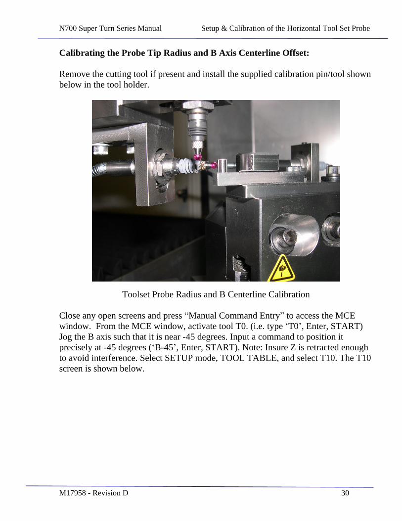
Calibrating the Probe Tip Radius and B Axis Centerline Offset:
Remove the cutting tool if present and install the supplied calibration pin/tool shown below in the tool holder.
Toolset Probe Radius and B Centerline Calibration
Close any open screens and press Manual Command Entry to access the MCE window. From the MCE window, activate tool T0. (i.e. type T0 , Enter, START) Jog the B axis such that it is near -45 degrees. Input a command to position it precisely at -45 degrees ( B-45 , Enter, START). Note: Insure Z is retracted enough to avoid interference. Select SETUP mode, TOOL TABLE, and select T10. The T10 screen is shown below.
N700 Super Turn Series Manual Setup & Calibration of the Horizontal Tool Set Probe
M17958 - Revision D 31
.
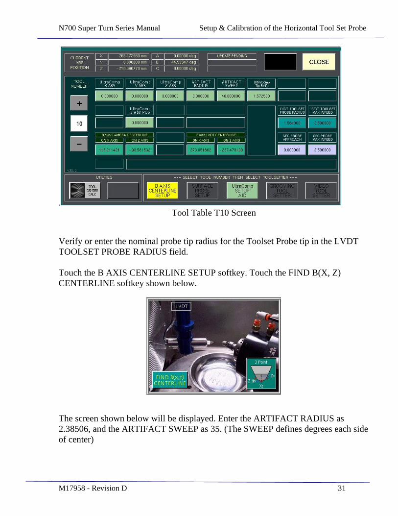
Tool Table T10 Screen
Verify or enter the nominal probe tip radius for the Toolset Probe tip in the LVDT TOOLSET PROBE RADIUS field.
Touch the B AXIS CENTERLINE SETUP softkey. Touch the FIND B(X, Z) CENTERLINE softkey shown below.
The screen shown below will be displayed. Enter the ARTIFACT RADIUS as 2.38506, and the ARTIFACT SWEEP as 35. (The SWEEP defines degrees each side of center)

N700 Super Turn Series Manual Setup & Calibration of the Horizontal Tool Set Probe
M17958 - Revision D 32
Find B Axis Centerline Screen
Jog the axes to position the horizontal toolset probe approximately on center of the calibration pin, and about 1mm away from the surface
Touch the BEGIN B-AXIS CL SETUP softkey, and then press the START pushbutton. The probe will touch three points on the pin to determine the X1, Z1, B1 and RAD1 values. Verify that the measured radius (CALC RAD 1) is within +/- .002mm of the ARTIFACT RADIUS. If it is not, calculate the difference between the two and make note whether it was too large or too small, then return to the Tool Table T10 screen shown above. If the measured radius was too large, make the LVDT TOOLSET PROBE RADIUS larger by the difference amount. If the measured radius was too small, make the probe radius smaller by that amount. Return to step 6 above and repeat the process until the correct measured radius is achieved.
Next, jog the Z slide back to avoid interference, and then touch the ROTATE B AXIS 90 DEG + POSITIVE + softkey. The B axis will rotate +90 degrees. Jog the axes to position the Toolset Probe approximately on center of the calibration pin, and about 1mm off from the surface. Touch the BEGIN B-AXIS CL SETUP softkey, and then press the START pushbutton. The probe will touch three points on the pin to determine the X2, Z2, B2 and RAD2 values, and the X & Z axes B Centerline values will be calculated. Verify that the results are shown, and then touch the CLOSE softkey. Touch YES to save the results to the Tool Table. The
N700 Super Turn Series Manual Setup & Calibration of the Horizontal Tool Set Probe
M17958 - Revision D 33
LVDT X and Z B Centerline values are stored in the Tool Table under T10. Close any open screens and remove the calibration artifact from the tool holder and store it in a labeled container.
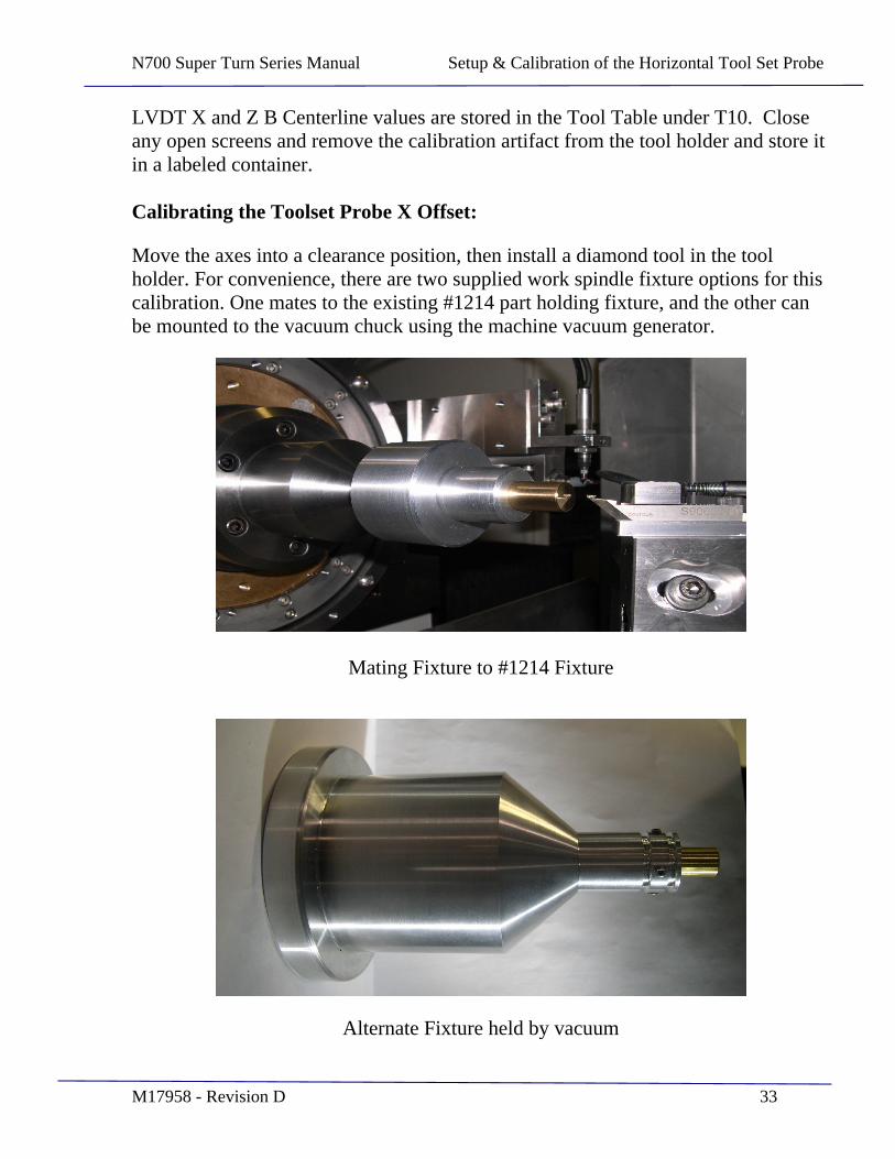
Calibrating the Toolset Probe X Offset:
Move the axes into a clearance position, then install a diamond tool in the tool holder. For convenience, there are two supplied work spindle fixture options for this calibration. One mates to the existing #1214 part holding fixture, and the other can be mounted to the vacuum chuck using the machine vacuum generator.
Mating Fixture to #1214 Fixture
Alternate Fixture held by vacuum
N700 Super Turn Series Manual Setup & Calibration of the Horizontal Tool Set Probe
M17958 - Revision D 34
Insert a pointer in the work spindle fixture and align it to run true. Move the tool so that the tool tip is near the pointer. Examine the vertical alignment and adjust the tool vertically if necessary. Jog the axes into clearance, then remove the pointer and insert the 17mm radius brass stud into the part holding fixture. Reposition the axes to put the tool visually at part center in the X direction, and slightly off the part in the Z direction. Select tool #5 in the Tool Table. Enter the nominal radius for the diamond tool in the RADIUS field. Touch the LOAD TOOL POSITIONS softkey, and then touch YES. Touch SAVE CHANGES, then CLOSE the tool table. From RUN mode, select the 17rcx.pgm part program, and START the program. STOP the program during the cutting path, and with SHIFT turned on, increment the Z slide in to touch off on the part surface. Use Continuous Jog to jog the tool back from the part surface, and then shift in the desired cut depth. Restart the program to cut the part surface. Continue with additional cutting passes, until the part surface is fully cleaned up. Evaluate the tool height and the X tool centering relative to spindle centerline, with offline measurement devices. Optimize the tool height by adjusting the tool holder, and adjust the X abs position in the tool table for tool #5, until ideal tool centering is achieved.
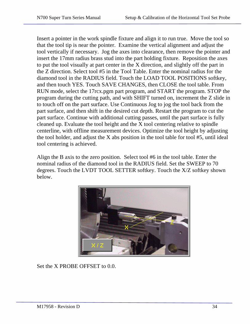
Align the B axis to the zero position. Select tool #6 in the tool table. Enter the nominal radius of the diamond tool in the RADIUS field. Set the SWEEP to 70 degrees. Touch the LVDT TOOL SETTER softkey. Touch the X/Z softkey shown below.
Set the X PROBE OFFSET to 0.0.
N700 Super Turn Series Manual Setup & Calibration of the Horizontal Tool Set Probe
M17958 - Revision D 35
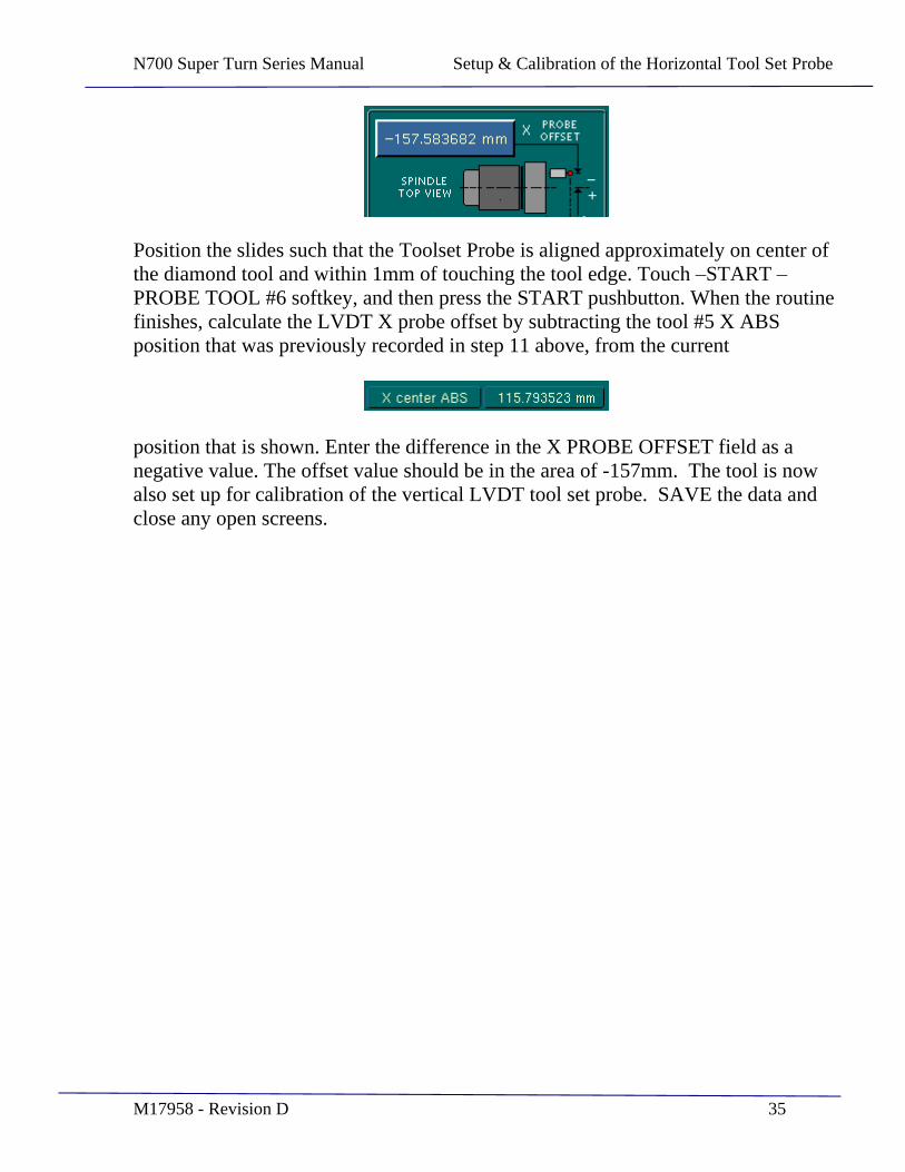
Position the slides such that the Toolset Probe is aligned approximately on center of the diamond tool and within 1mm of touching the tool edge. Touch START
PROBE TOOL #6 softkey, and then press the START pushbutton. When the routine finishes, calculate the LVDT X probe offset by subtracting the tool #5 X ABS position that was previously recorded in step 11 above, from the current
position that is shown. Enter the difference in the X PROBE OFFSET field as a negative value. The offset value should be in the area of -157mm. The tool is now also set up for calibration of the vertical LVDT tool set probe. SAVE the data and close any open screens.

N700 Super Turn Series Manual Setup & Calibration of the Horizontal Tool Set Probe
M17958 - Revision D 36
CALIBRATION RECORD FOR THE LVDT TOOL SET PROBES
SETTING HEIGHT OF HORIZONTAL PROBE Goal Actual
Fixture TIR 0.005 mm Max Height Difference 0.010 mm Max Operator Date
HORIZONTAL LVDT TOOL SETTER RUBY PROBE TIP RADIUS Example Actual
Artifact Radius 2.38506 mm LVDT Tool Set Probe Radius
1.5840 mm
Sweep 35 Degrees X1 Z1 B1 RAD1 1.5840 RAD1=Probe Radius?
YES If difference over 0.002 mm, adjust LVDT Tool Set Probe Radius, repeat
Operator Date
HORIZONTAL LVDT TOOL SETTER OFFSET TO B AXIS CENTERLINE Example Actual
X2 Z2 B2 RAD2 1.5840 B(X) CL 273.0000 mm B(Z) CL -231.0000 mm Save Results Yes Results shown in T10 tool table?
Yes
Operator Date
LVDT TOOL SETTER OFFSET TO SPINDLE CENTERLINE Goal Actual
X Center Error of Turned Stud
0.001 mm
Height Error of Turned Stud
0.002 mm
X Center ABS Value -157.0000 mm Vertical Probe Height
Under 0.002 mm Operator Date
N700 Super Turn Series Manual Setup & Calibration of the Vertical LVDT Tool Set Probe
M17958 - Revision D 37
SECTION 5
Setup & Calibration of the Vertical LVDT Tool Set Probe

N700 Super Turn Series Manual Setup & Calibration of the Vertical LVDT Tool Set Probe
M17958 - Revision D 38
Initially a tool must be setup at the proper spindle centerline height by cutting a part, measuring height error using an offline microscope, and adjusting the tool holder manually to correct for the error. Once a tool is properly set, the vertical LVDT is then mechanically adjusted to read zero at the correct tool height.
Vertical Toolset Probe
From COMMAND INPUT, execute an M18 command to raise the probe tip. Jog the slides to position the probe tip directly above the tool. Execute an M17 command to lower the probe tip onto the tool.
Select SETUP mode, touch MORE, and then touch SERVO MONITOR & TOOLS.
Open the GAGE AMPLIFIER screen by touching the softkey. The Vertical Toolset Probe is shown as Channel D. Loosen the 2 socket head cap screws which secure the probe bracket, and adjust the probe height until channel D reads zero.

N700 Super Turn Series Manual Setup & Calibration of the Vertical LVDT Tool Set Probe
M17958 - Revision D 39
Tip: Slightly snug the mounting screws with the height reading appearing to be slightly low, and then lightly tap the probe bracket down until zero is attained. Then secure the mounting screws.
Execute an M18 command to raise the probe tip, and then retract the tool from the set position by jogging the Z slide. CLOSE the Gage Amplifier window, and CLOSE Servo Monitor & Tools.
N700 Super Turn Series Manual Setup & Calibration of the Part Surface Probe
M17958 - Revision D 40
SECTION 6
Setup & Calibration of the Part Surface Probe
N700 Super Turn Series Manual Setup & Calibration of the Part Surface Probe
M17958 - Revision D 41
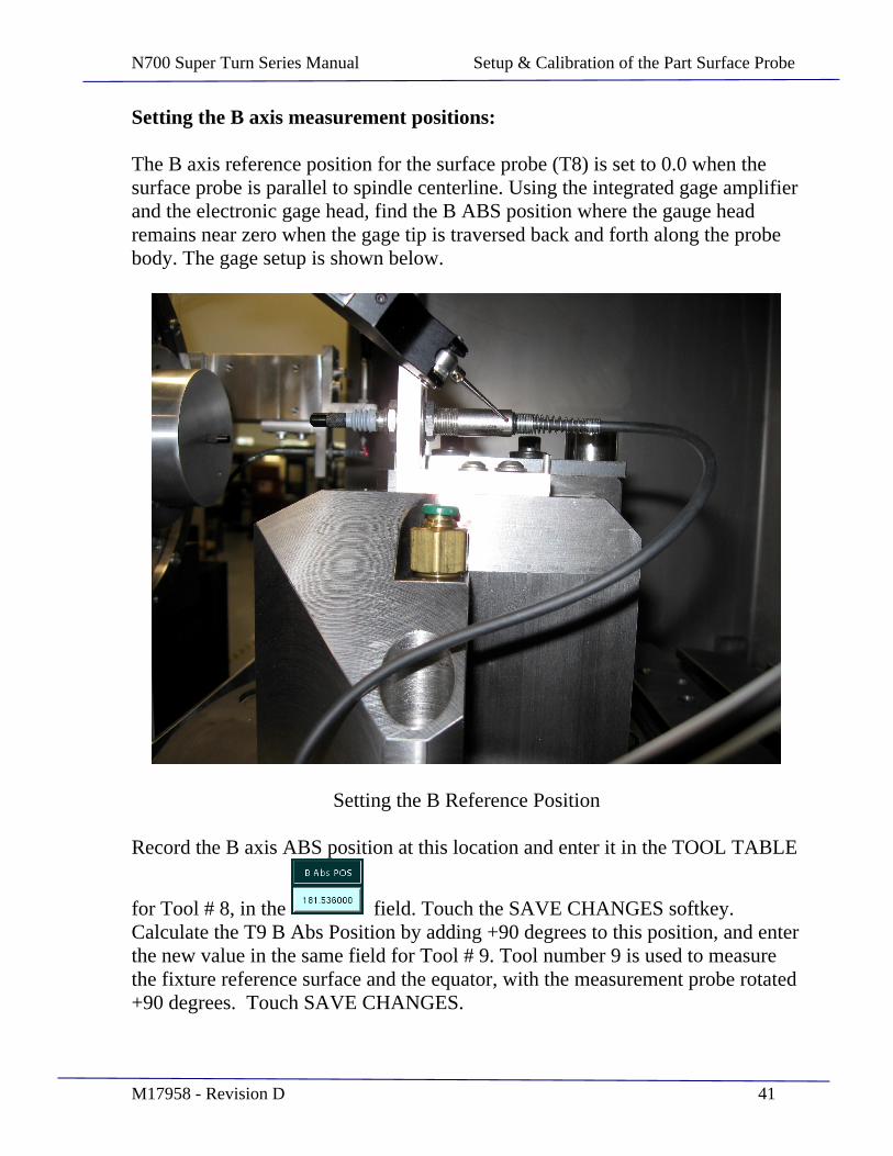
Setting the B axis measurement positions:
The B axis reference position for the surface probe (T8) is set to 0.0 when the surface probe is parallel to spindle centerline. Using the integrated gage amplifier and the electronic gage head, find the B ABS position where the gauge head remains near zero when the gage tip is traversed back and forth along the probe body. The gage setup is shown below.
Setting the B Reference Position
Record the B axis ABS position at this location and enter it in the TOOL TABLE
for Tool # 8, in the field. Touch the SAVE CHANGES softkey. Calculate the T9 B Abs Position by adding +90 degrees to this position, and enter the new value in the same field for Tool # 9. Tool number 9 is used to measure the fixture reference surface and the equator, with the measurement probe rotated +90 degrees. Touch SAVE CHANGES.
N700 Super Turn Series Manual Setup & Calibration of the Part Surface Probe
M17958 - Revision D 42
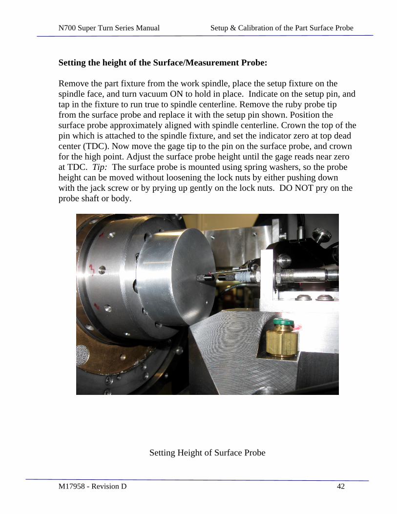
Setting the height of the Surface/Measurement Probe:
Remove the part fixture from the work spindle, place the setup fixture on the spindle face, and turn vacuum ON to hold in place. Indicate on the setup pin, and tap in the fixture to run true to spindle centerline. Remove the ruby probe tip from the surface probe and replace it with the setup pin shown. Position the surface probe approximately aligned with spindle centerline. Crown the top of the pin which is attached to the spindle fixture, and set the indicator zero at top dead center (TDC). Now move the gage tip to the pin on the surface probe, and crown for the high point. Adjust the surface probe height until the gage reads near zero at TDC. Tip: The surface probe is mounted using spring washers, so the probe height can be moved without loosening the lock nuts by either pushing down with the jack screw or by prying up gently on the lock nuts. DO NOT pry on the probe shaft or body.
Setting Height of Surface Probe
N700 Super Turn Series Manual Setup & Calibration of the Part Surface Probe
M17958 - Revision D 43
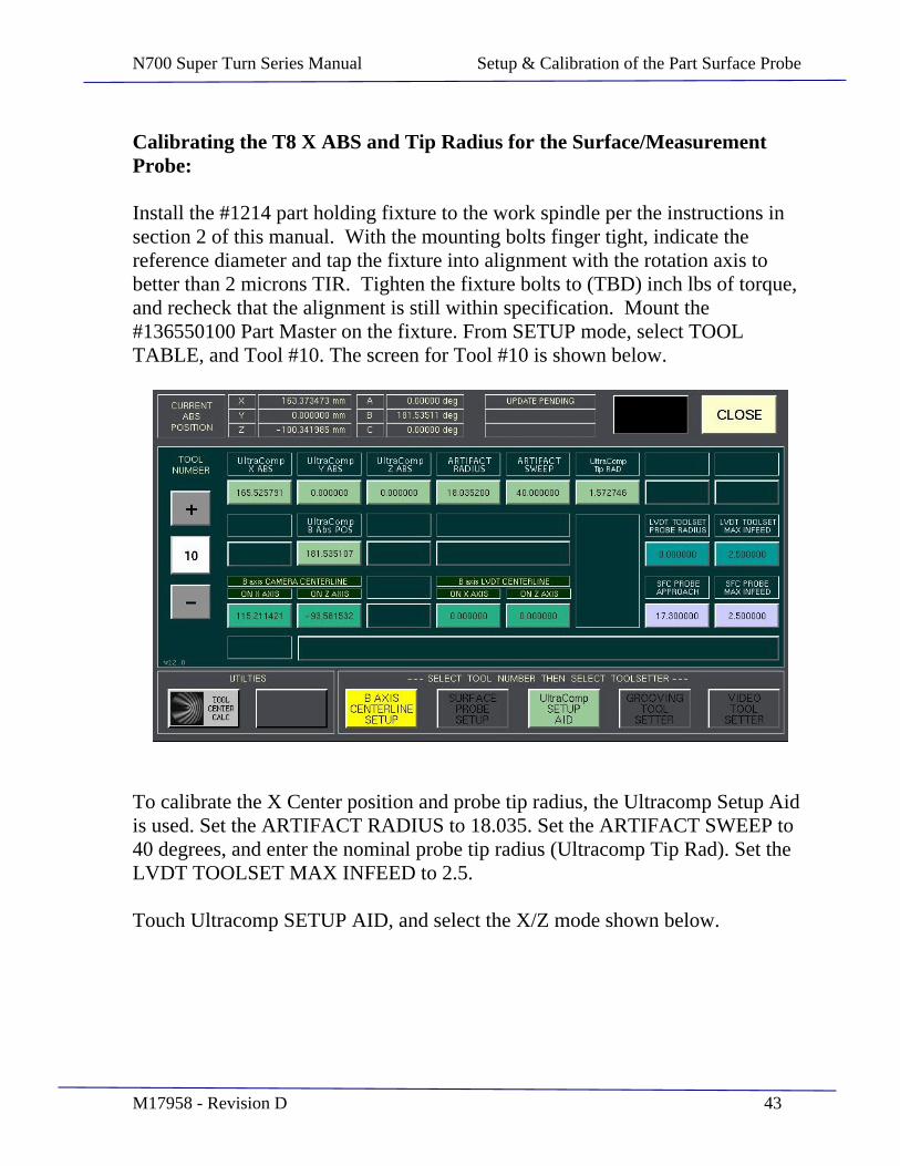
Calibrating the T8 X ABS and Tip Radius for the Surface/Measurement Probe:
Install the #1214 part holding fixture to the work spindle per the instructions in section 2 of this manual. With the mounting bolts finger tight, indicate the reference diameter and tap the fixture into alignment with the rotation axis to better than 2 microns TIR. Tighten the fixture bolts to (TBD) inch lbs of torque, and recheck that the alignment is still within specification. Mount the #136550100 Part Master on the fixture. From SETUP mode, select TOOL TABLE, and Tool #10. The screen for Tool #10 is shown below.
To calibrate the X Center position and probe tip radius, the Ultracomp Setup Aid is used. Set the ARTIFACT RADIUS to 18.035. Set the ARTIFACT SWEEP to 40 degrees, and enter the nominal probe tip radius (Ultracomp Tip Rad). Set the LVDT TOOLSET MAX INFEED to 2.5.
Touch Ultracomp SETUP AID, and select the X/Z mode shown below.

N700 Super Turn Series Manual Setup & Calibration of the Part Surface Probe
M17958 - Revision D 44
The screen shown below will appear.
Position the slides such that the surface probe is approximately on center and within 1mm of the Part Master. Touch BEGIN Ultracomp Setup, and then press the START pushbutton. The routine will probe the Part Master at three points and display the X and Z center ABS positions, and the calculated part radius. Compare the calculated radius value to the known 18.035 Part Master radius. If the calculated radius is not within 0.5um, calculate the difference and make note of the error being large or small. CLOSE the window to return to the Tool Table #10 screen. Adjust the current Ultracomp Tip RAD by the difference.
N700 Super Turn Series Manual Setup & Calibration of the Part Surface Probe
M17958 - Revision D 45
If the calculated radius was too small, make the Ultracomp Tip RAD smaller by the amount of error. Likewise, if the radius was too large make the tip radius larger. Repeat step 4 until the calculated radius is calibrated. Touch CLOSE and SAVE the data to the Tool Table. Record the Ultracomp X ABS and the Ultracomp Tip RAD shown in Tool #10. Enter the X ABS value in the X ABS field for Tool #8. Enter the Tip RAD value in the RADIUS field for both Tool #8 and Tool #9.
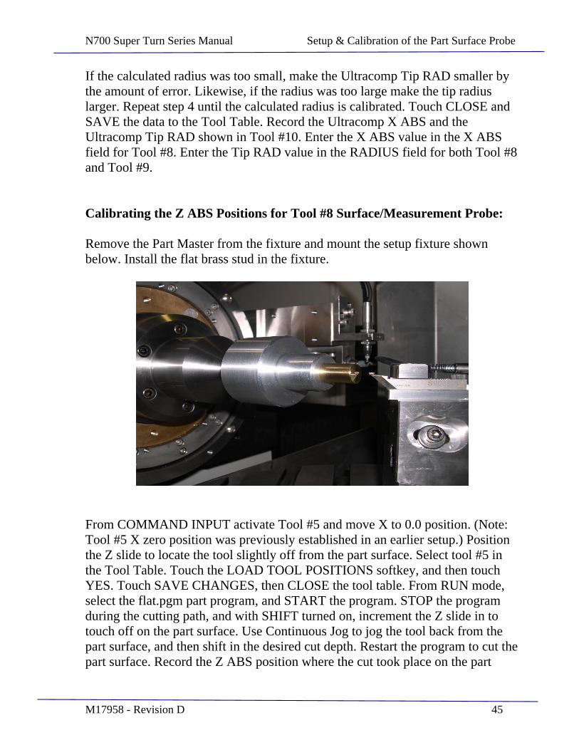
Calibrating the Z ABS Positions for Tool #8 Surface/Measurement Probe:
Remove the Part Master from the fixture and mount the setup fixture shown below. Install the flat brass stud in the fixture.
From COMMAND INPUT activate Tool #5 and move X to 0.0 position. (Note: Tool #5 X zero position was previously established in an earlier setup.) Position the Z slide to locate the tool slightly off from the part surface. Select tool #5 in the Tool Table. Touch the LOAD TOOL POSITIONS softkey, and then touch YES. Touch SAVE CHANGES, then CLOSE the tool table. From RUN mode, select the flat.pgm part program, and START the program. STOP the program during the cutting path, and with SHIFT turned on, increment the Z slide in to touch off on the part surface. Use Continuous Jog to jog the tool back from the part surface, and then shift in the desired cut depth. Restart the program to cut the part surface. Record the Z ABS position where the cut took place on the part
N700 Super Turn Series Manual Setup & Calibration of the Part Surface Probe
M17958 - Revision D 46
surface as TOOL Z AT PART. (Note: For this example, actual machine position values will be used to clarify sign conventions.)
TOOL Z AT PART = -158.964914
Cancel any SHIFT value by entering an MCE command of G92 . Move X axis to the (+LVDT X OFFSET) (i.e. 157.584) position. This will position the probe in line with the Toolset Probe. Select SETUP mode, touch MORE, and then touch SERVO MONITOR & TOOLS. Open the GAGE
AMPLIFIER screen by touching the softkey. The Horizontal Toolset Probe is shown as Channel C. Jog the Z slide in (minus) until the tool touches the probe, then use the incremental jog feature to zero the gage amp reading. Record this Z ABS position as TOOL Z AT PROBE.
TOOL Z AT PROBE = -226.884314
Now calculate the PART TO LVDT Z CENTER distance as: PART TO LVDT = TOOL Z AT PROBE TOOL Z AT PART TEST PROBE RADIUS PART TO LVDT = -226.884314 (-158.964914) 1.554 PART TO LVDT = - 69.4734
From COMMAND INPUT, activate Tool #8 and move B axis to 0.0 position. Jog the slides to position the surface probe on the part surface, and watching Channel F, adjust the Z position until the gage amp reads 0.0. Record the current Z ABS position as SURFACE PROBE AT PART.
SURFACE PROBE AT PART = -53.520288
Next calculate the SURFACE PROBE AT TOOLSET PROBE position as:
SURF PROBE AT TSET PROBE = SURF PROBE AT PART + PART TO LVDT SURF PROBE AT TSET PROBE = -53.520288 + (-69.4734) SURF PROBE AT TSET PROBE = -122.993688
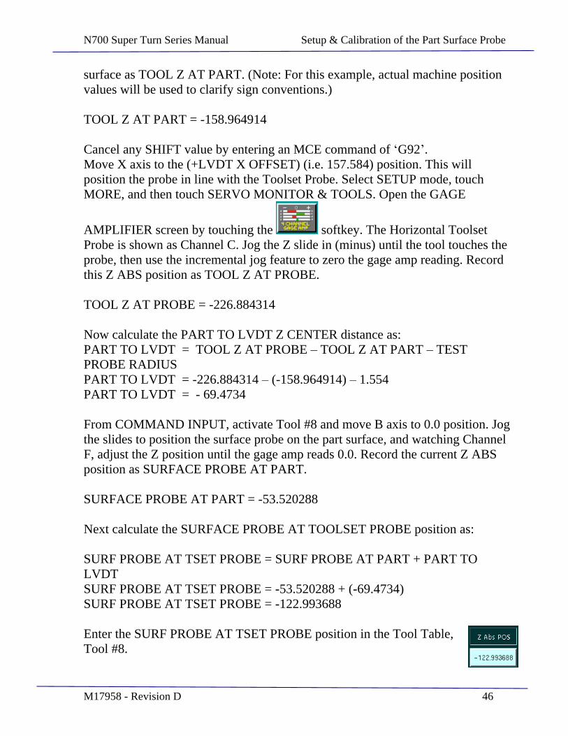
Enter the SURF PROBE AT TSET PROBE position in the Tool Table, Tool #8.
N700 Super Turn Series Manual Setup & Calibration of the Part Surface Probe
M17958 - Revision D 47
Touch SAVE CHANGES after it appears.
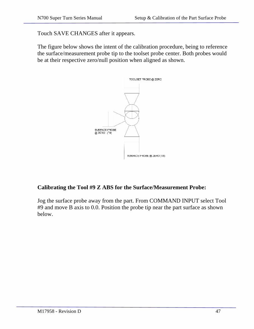
The figure below shows the intent of the calibration procedure, being to reference the surface/measurement probe tip to the toolset probe center. Both probes would be at their respective zero/null position when aligned as shown.
Calibrating the Tool #9 Z ABS for the Surface/Measurement Probe:
Jog the surface probe away from the part. From COMMAND INPUT select Tool #9 and move B axis to 0.0. Position the probe tip near the part surface as shown below.
N700 Super Turn Series Manual Setup & Calibration of the Part Surface Probe
M17958 - Revision D 48
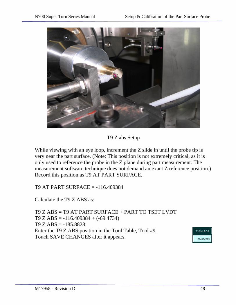
T9 Z abs Setup
While viewing with an eye loop, increment the Z slide in until the probe tip is very near the part surface. (Note: This position is not extremely critical, as it is only used to reference the probe in the Z plane during part measurement. The measurement software technique does not demand an exact Z reference position.) Record this position as T9 AT PART SURFACE.
T9 AT PART SURFACE = -116.409384
Calculate the T9 Z ABS as:
T9 Z ABS = T9 AT PART SURFACE + PART TO TSET LVDT T9 Z ABS = -116.409384 + (-69.4734) T9 Z ABS = -185.8828 Enter the T9 Z ABS position in the Tool Table, Tool #9. Touch SAVE CHANGES after it appears.
N700 Super Turn Series Manual Setup & Calibration of the Part Surface Probe
M17958 - Revision D 49
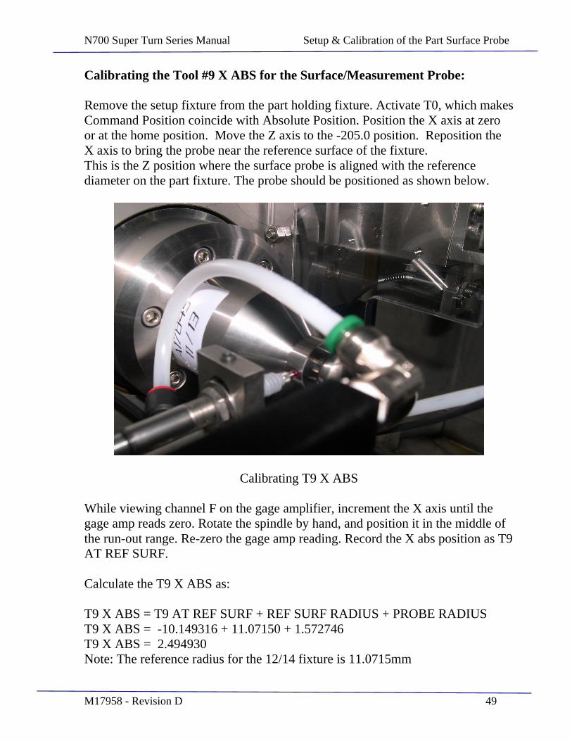
Calibrating the Tool #9 X ABS for the Surface/Measurement Probe:
Remove the setup fixture from the part holding fixture. Activate T0, which makes Command Position coincide with Absolute Position. Position the X axis at zero or at the home position. Move the Z axis to the -205.0 position. Reposition the X axis to bring the probe near the reference surface of the fixture. This is the Z position where the surface probe is aligned with the reference diameter on the part fixture. The probe should be positioned as shown below.
Calibrating T9 X ABS
While viewing channel F on the gage amplifier, increment the X axis until the gage amp reads zero. Rotate the spindle by hand, and position it in the middle of the run-out range. Re-zero the gage amp reading. Record the X abs position as T9 AT REF SURF.
Calculate the T9 X ABS as:
T9 X ABS = T9 AT REF SURF + REF SURF RADIUS + PROBE RADIUS T9 X ABS = -10.149316 + 11.07150 + 1.572746 T9 X ABS = 2.494930 Note: The reference radius for the 12/14 fixture is 11.0715mm

N700 Super Turn Series Manual Setup & Calibration of the Part Surface Probe
M17958 - Revision D 50
The reference radius for the 11/13 fixture is 11.0769mm The probe radius is currently shown under T9 RADIUS
This calibration can be performed using either fixture.
Enter the result in the T9 field, and SAVE the changes.
Establishing the Surface Probe Z reference Position(s) to the Part Fixture(s):
To safely guard the surface probe from bottoming out in a component failure type condition, the surface probe needs to know roughly where to look for the part surface. The maximum hard travel of the probe is approximately 3mm, so typically the maximum allowed probe infeed is set to 2.5mm. If the surface probe does not find the part within 2.5mm of the start point, the cycle is aborted and a PROBE AWAY error message is displayed. The position at which the probe
starts to look for the part is calculated based on part parameters which define the specific part in the user P-Table file, as well as a known fixture dimension.
Specifically, the part dimension is from the reference diameter on the taper to the pole of the part. This is specified in the user P-table. A known dimension for each fixture was determined at the factory which defines the distance from the reference diameter on the fixture taper to the end of the fixture. The surface probe is then referenced to the end of each fixture, which is then used in the probe start calculation. The fixture end reference position is not a critical calibration, and is only used to determine the relative probe starting point. It will likely not require any adjustment, unless the probe location is moved. A separate fixture end reference position must be defined for each fixture. The reference positions are command CMD positions with tool #8 active, and are parameter settings which reside in the surface.probe file, which resides on the /pgm directory. The parameter entries in the file are shown below.
; surface.probe 09/23/2009 ; Surface Probing routine ; The setup parameters below MUST be configured to the specific ; machine setup for each of two fixtures. ;
N700 Super Turn Series Manual Setup & Calibration of the Part Surface Probe
M17958 - Revision D 51
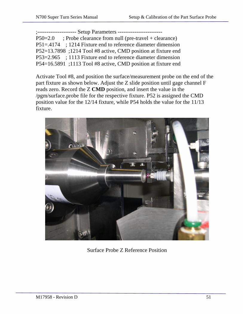
;--------------------- Setup Parameters ------------------------ P50=2.0 ; Probe clearance from null (pre-travel + clearance) P51=.4174 ; 1214 Fixture end to reference diameter dimension P52=13.7898 ;1214 Tool #8 active, CMD position at fixture end P53=2.965 ; 1113 Fixture end to reference diameter dimension P54=16.5891 ;1113 Tool #8 active, CMD position at fixture end
Activate Tool #8, and position the surface/measurement probe on the end of the part fixture as shown below. Adjust the Z slide position until gage channel F reads zero. Record the Z CMD position, and insert the value in the /pgm/surface.probe file for the respective fixture. P52 is assigned the CMD position value for the 12/14 fixture, while P54 holds the value for the 11/13 fixture.
Surface Probe Z Reference Position

N700 Super Turn Series Manual Setup & Calibration of the Part Surface Probe
M17958 - Revision D 52
This page intentionally left blank.
N700 Super Turn Series Manual Setup & Calibration of the Part Surface Probe
M17958 - Revision D 53
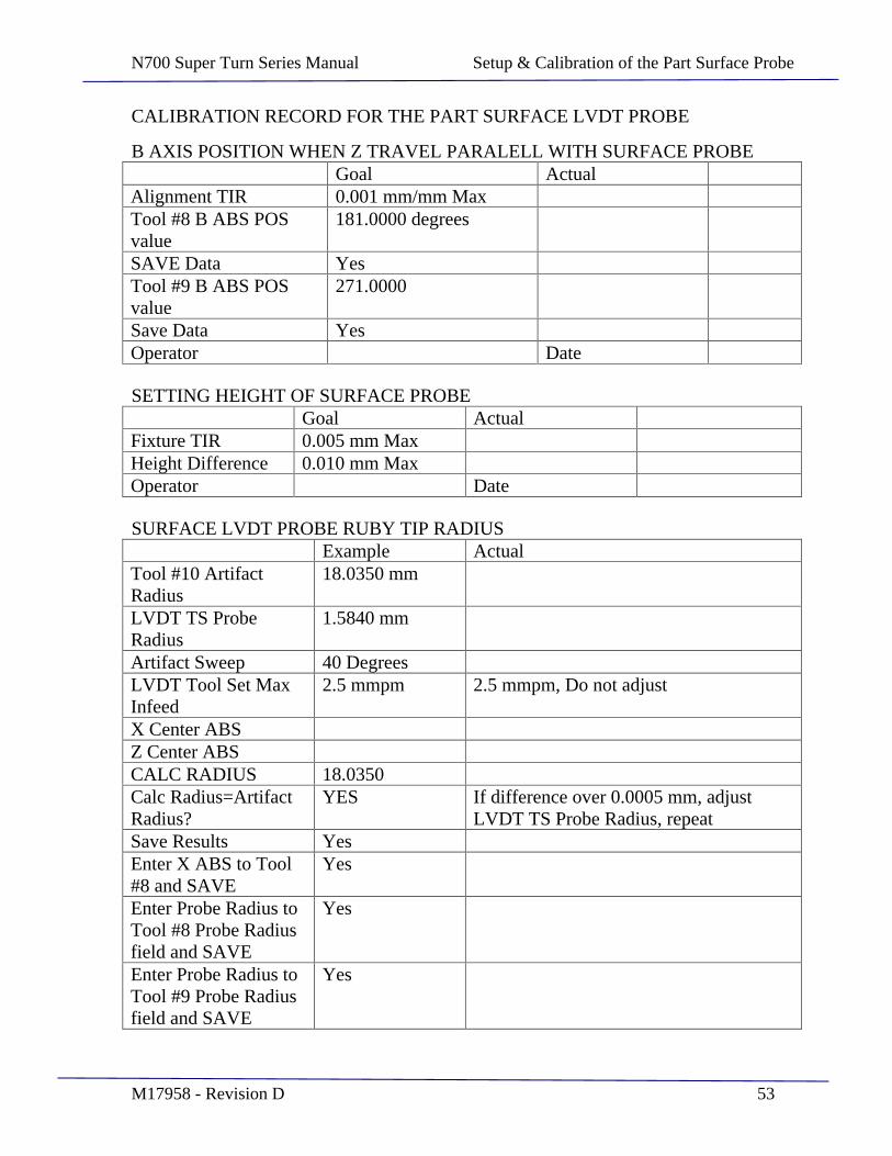
CALIBRATION RECORD FOR THE PART SURFACE LVDT PROBE
B AXIS POSITION WHEN Z TRAVEL PARALELL WITH SURFACE PROBE Goal Actual
Alignment TIR 0.001 mm/mm Max Tool #8 B ABS POS value
181.0000 degrees
SAVE Data Yes Tool #9 B ABS POS value
271.0000
Save Data Yes Operator Date
SETTING HEIGHT OF SURFACE PROBE Goal Actual
Fixture TIR 0.005 mm Max Height Difference 0.010 mm Max Operator Date
SURFACE LVDT PROBE RUBY TIP RADIUS Example Actual
Tool #10 Artifact Radius
18.0350 mm
LVDT TS Probe Radius
1.5840 mm
Artifact Sweep 40 Degrees LVDT Tool Set Max Infeed
2.5 mmpm 2.5 mmpm, Do not adjust
X Center ABS Z Center ABS CALC RADIUS 18.0350 Calc Radius=Artifact Radius?
YES If difference over 0.0005 mm, adjust LVDT TS Probe Radius, repeat
Save Results Yes Enter X ABS to Tool #8 and SAVE
Yes
Enter Probe Radius to Tool #8 Probe Radius field and SAVE
Yes
Enter Probe Radius to Tool #9 Probe Radius field and SAVE
Yes
N700 Super Turn Series Manual Setup & Calibration of the Part Surface Probe
M17958 - Revision D 54
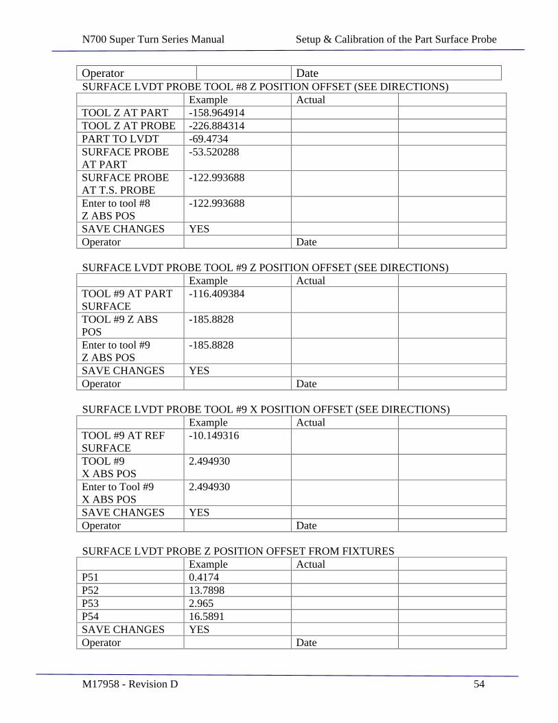
Operator Date SURFACE LVDT PROBE TOOL #8 Z POSITION OFFSET (SEE DIRECTIONS)
Example Actual TOOL Z AT PART -158.964914 TOOL Z AT PROBE -226.884314 PART TO LVDT -69.4734 SURFACE PROBE AT PART
-53.520288
SURFACE PROBE AT T.S. PROBE
-122.993688
Enter to tool #8 Z ABS POS
-122.993688
SAVE CHANGES YES Operator Date
SURFACE LVDT PROBE TOOL #9 Z POSITION OFFSET (SEE DIRECTIONS) Example Actual
TOOL #9 AT PART SURFACE
-116.409384
TOOL #9 Z ABS POS
-185.8828
Enter to tool #9 Z ABS POS
-185.8828
SAVE CHANGES YES Operator Date
SURFACE LVDT PROBE TOOL #9 X POSITION OFFSET (SEE DIRECTIONS) Example Actual
TOOL #9 AT REF SURFACE
-10.149316
TOOL #9 X ABS POS
2.494930
Enter to Tool #9 X ABS POS
2.494930
SAVE CHANGES YES Operator Date
SURFACE LVDT PROBE Z POSITION OFFSET FROM FIXTURES Example Actual
P51 0.4174 P52 13.7898 P53 2.965 P54 16.5891 SAVE CHANGES YES Operator Date
N700 Super Turn Series Manual Bar Code Scanner Operation
M17958 - Revision D 55
SECTION 7
Bar Code Scanner Operation
N700 Super Turn Series Manual Bar Code Scanner Operation
M17958 - Revision D 56
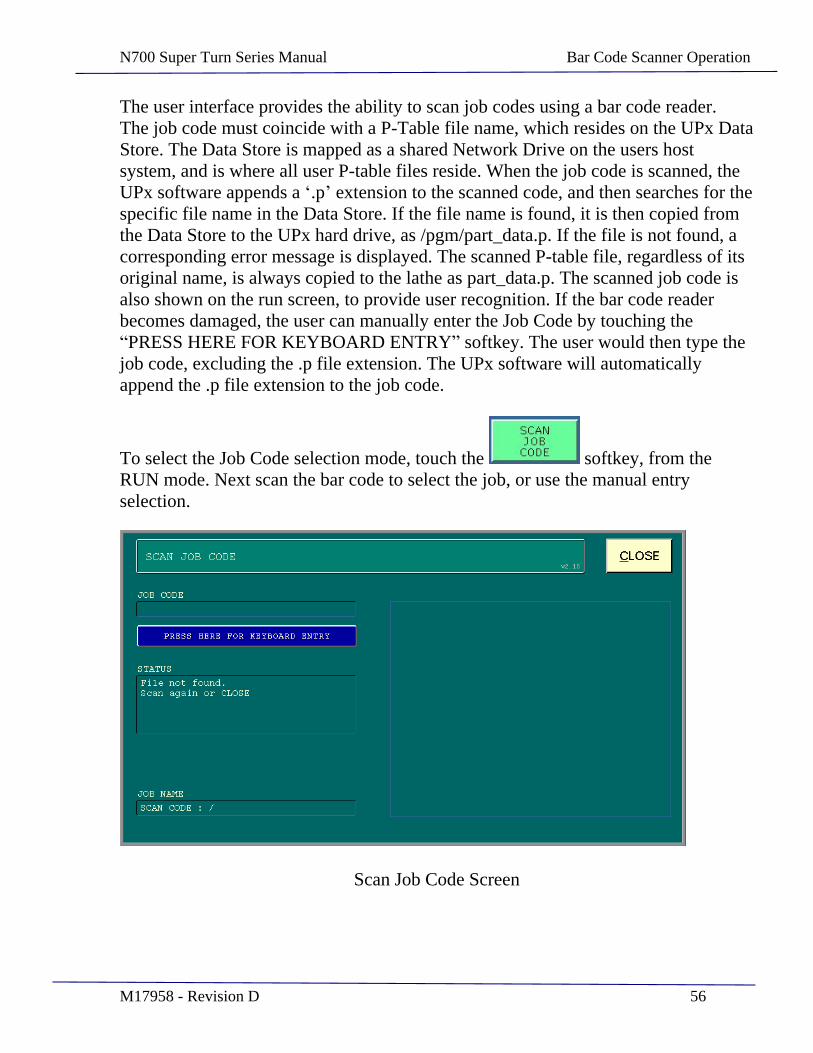
The user interface provides the ability to scan job codes using a bar code reader. The job code must coincide with a P-Table file name, which resides on the UPx Data Store. The Data Store is mapped as a shared Network Drive on the users host system, and is where all user P-table files reside. When the job code is scanned, the UPx software appends a .p extension to the scanned code, and then searches for the specific file name in the Data Store. If the file name is found, it is then copied from the Data Store to the UPx hard drive, as /pgm/part_data.p. If the file is not found, a corresponding error message is displayed. The scanned P-table file, regardless of its original name, is always copied to the lathe as part_data.p. The scanned job code is also shown on the run screen, to provide user recognition. If the bar code reader becomes damaged, the user can manually enter the Job Code by touching the PRESS HERE FOR KEYBOARD ENTRY softkey. The user would then type the
job code, excluding the .p file extension. The UPx software will automatically append the .p file extension to the job code.
To select the Job Code selection mode, touch the softkey, from the RUN mode. Next scan the bar code to select the job, or use the manual entry selection.
Scan Job Code Screen
N700 Super Turn Series Manual Bar Code Scanner Operation
M17958 - Revision D 57
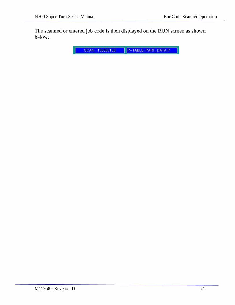
The scanned or entered job code is then displayed on the RUN screen as shown below.
N700 Super Turn Series Manual Machining & Inspection Process Sequence
M17958 - Revision D 58
SECTION 8
Machining & Inspection Process Sequence
N700 Super Turn Series Manual Machining & Inspection Process Sequence
M17958 - Revision D 59
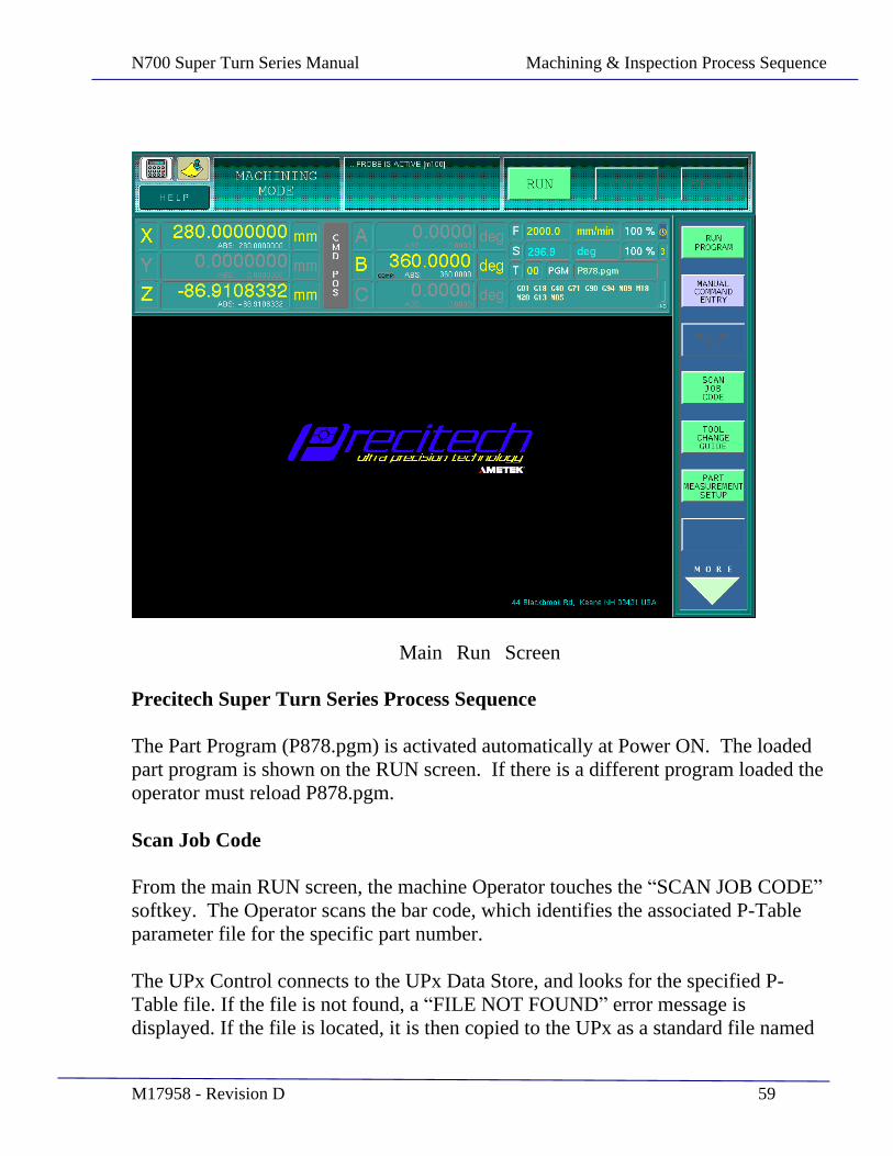
Main Run Screen
Precitech Super Turn Series Process Sequence
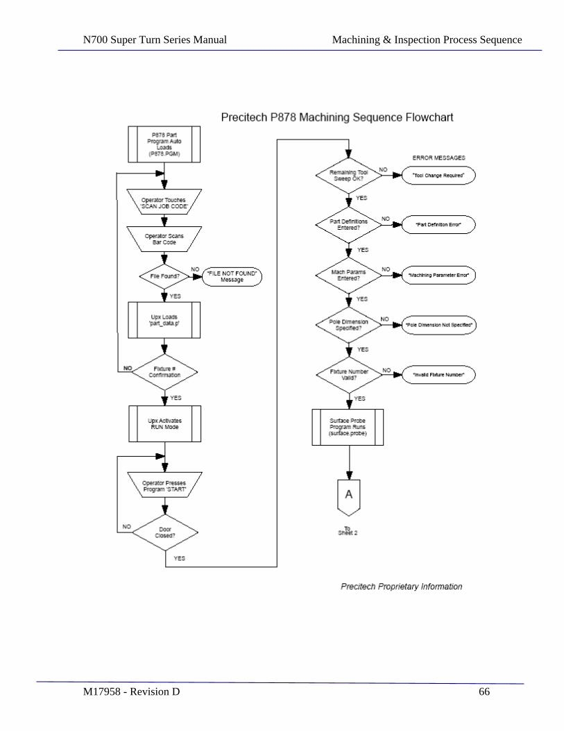
The Part Program (P878.pgm) is activated automatically at Power ON. The loaded part program is shown on the RUN screen. If there is a different program loaded the operator must reload P878.pgm.
Scan Job Code
From the main RUN screen, the machine Operator touches the SCAN JOB CODE softkey. The Operator scans the bar code, which identifies the associated P-Table parameter file for the specific part number.
The UPx Control connects to the UPx Data Store, and looks for the specified P-Table file. If the file is not found, a FILE NOT FOUND error message is displayed. If the file is located, it is then copied to the UPx as a standard file named
N700 Super Turn Series Manual Machining & Inspection Process Sequence
M17958 - Revision D 60
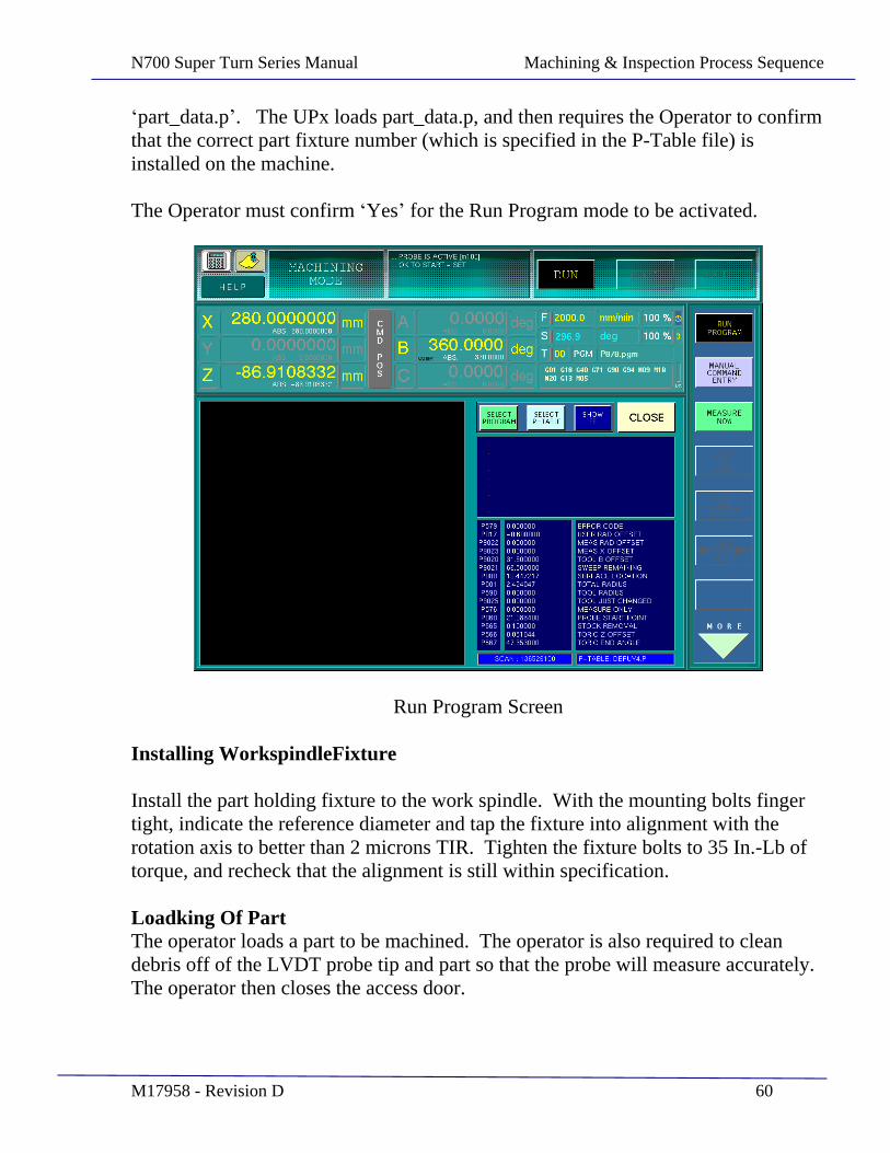
part_data.p . The UPx loads part_data.p, and then requires the Operator to confirm that the correct part fixture number (which is specified in the P-Table file) is installed on the machine.
The Operator must confirm Yes for the Run Program mode to be activated.
Run Program Screen
Installing WorkspindleFixture
Install the part holding fixture to the work spindle. With the mounting bolts finger tight, indicate the reference diameter and tap the fixture into alignment with the rotation axis to better than 2 microns TIR. Tighten the fixture bolts to 35 In.-Lb of torque, and recheck that the alignment is still within specification.
Loadking Of Part The operator loads a part to be machined. The operator is also required to clean debris off of the LVDT probe tip and part so that the probe will measure accurately. The operator then closes the access door.

N700 Super Turn Series Manual Machining & Inspection Process Sequence
M17958 - Revision D 61
Starting Of The Program Cycle
The Operator then presses the START pushbutton. The cycle will not start unless both access doors are closed. The program surface.probe is then started. The program checks that the usable tool sweep is not expired. If there is no remaining unused tool sweep, the program is immediately aborted with an Error Code 1 (shown in the P-Watch window) and the error message INSERT CHANGE REQUIRED is displayed.
The program checks that all relevant Part definition parameters are non-zero. If one is zero, the program aborts with an Error Code 2 , displaying the message PART DEFINITION ERROR .
The program checks that all relevant Machining parameters are non-zero. If one is zero, the program aborts with an Error Code 3 , displaying the message MACHINING PARAMETER ERROR .
The program checks for verification that the Pole to Fixture Reference Diameter parameter is non-zero. If it is zero, the program is aborted with an Error Code 4 , displaying the message POLE DIMENSION NOT SPECIFIED .
The program checks that a valid fixture number is specified. The fixture number conditionally identifies a related set of predefined parameters which are used to determine the general part location in the Z plane, for probing the part. If the fixture number is not valid, the program aborts with an Error Code 5 , displaying the message INVALID FIXTURE NUMBER .
Surface Probing Routine
Surface probing next occurs to determine the precise location of the part surface in the Z direction. A position offset is captured, which is relative to the tool center and the surface/measurement probe. If the MEASURE NOW feature is selected in the user interface, execution continues with the part measurement cycle. If it is not selected, program execution (part machining) continues as described below.
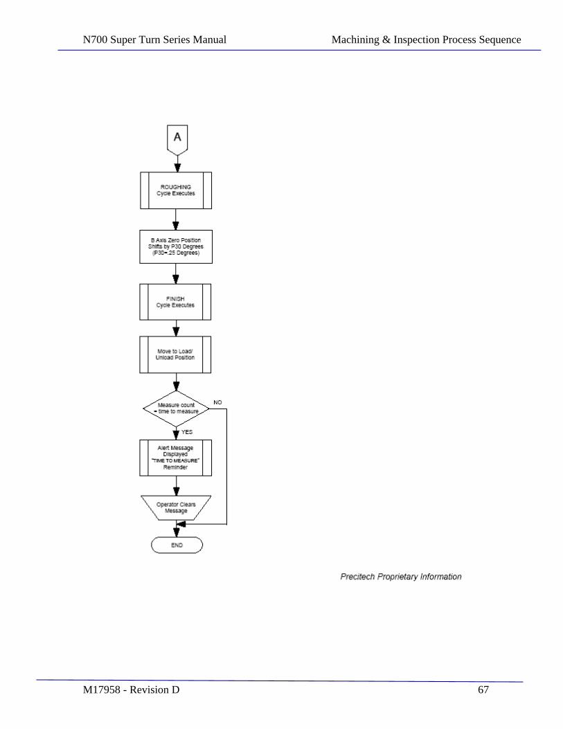
Part Machining Routine
The required stock removal (in the Z direction) from the raw part face is calculated based on the nominal raw part diameter and the finished part radius, which are both specified in the part specific P-Table file. This value is subtracted from the above

N700 Super Turn Series Manual Machining & Inspection Process Sequence
M17958 - Revision D 62
position offset, to set the finish pass location at the desired depth below the raw part surface.
The Rough Pass machining cycle is executed. At the end of the roughing pass, the tool contact point angle (B axis position) is incremented by variable P30 in degrees. In this manner the tool angle is shifted prior to each finish pass cycle, providing a fresh spot on the tool and spreading the tool wear across the tool face.
The Finish Pass machining cycle is executed. In both Rough and Finish cycles, the stock removal is controlled by adjusting the current part radii dimensions, which achieves consistent stock removal about the surface.
The machine moves to the part load/unload position. The part measurement counter is evaluated, and if the count is equal to the set Measure Frequency, an alert message is displayed as a reminder to measure the part. The user may then select MEASURE MODE if desired, or continue with additional part cutting.
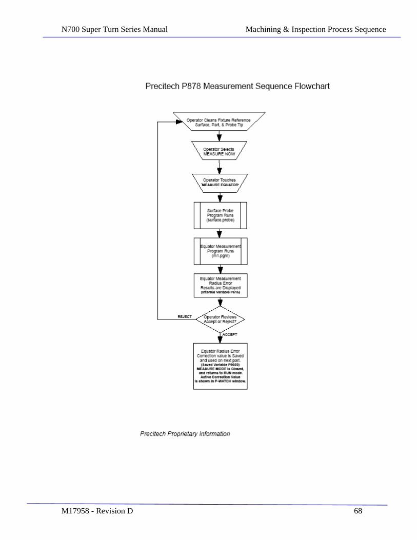
Part Measurement Routine
At this time the process stops for operator involvement. The operator must open the doors and access the working zone. The ruby stylus tip for the measurement probe must be cleaned and the freshly machined part must be cleaned so that the measurement will be accurate.
If this routine is being executed on an infrequent basis, such as once for every 10 parts, then it is also a good time to review the quantity of machining chips present and clean these out from the machining zone. Wearing protective gloves, collect the chips by hand and dispose of them properly. It is also allowed to use a vacuum cleaner, brush, or squeegee to collect the chips. It is not allowed to use an air gun as this can displace cutting chips into places on the machine where they may cause damage to the machine. The operator must close the door to proceed with the measurement routine.
Part Measurement Routine Overview
he Precitech Super Turn Series lathe configuration provides the ability to measure the part equator radius using the on machine LVDT surface probe. The resultant measurement error may then be used as an automatic correction adjustment in the next machining cycle. The user has the option to select a measurement interval, which then alerts the operator with a displayed message that it is time to measure the
N700 Super Turn Series Manual Machining & Inspection Process Sequence
M17958 - Revision D 63
part. The operator then has the option to measure the part, or decline the measurement and continue cutting. The message alert is a reminder only, as part measurement is allowed to be selected at any time part cutting is not in process. Whenever a part fixture is remounted on the spindle, it is a requirement that the automated Fixture Calibration routine is executed. The calibration routine determines the amount of mechanical run-out in the mounting of the fixture, and adjusts the reference surface radius parameter to compensate for this run-out. It is however equally important that the user mechanically aligns the fixture to run concentric to spindle rotation to less than 2um, prior to running the calibration cycle. Each fixture has an associated Part Master and supporting P-Table which defines the specific parameters of the respective master. It is very important that the correct Part Master for the respective fixture is used with that fixture for calibration, or possible damage to the probe could occur. The associated P-Table file for the respective fixture is automatically loaded when the user selects the fixture he wishes to calibrate. The 11/13 Fixture uses file 1113master.p and the 12/14 Fixture uses 1214master.p .
Part Measurement Fixture Calibration
Once the fixture has been mounted on the spindle and indicated in concentric to spindle centerline to < 2um, it is then necessary to run the calibration routine. Place the corresponding Part Master on the fixture. From the RUN mode select MEASUREMENT SETUP. The screen below will be displayed.
N700 Super Turn Series Manual Machining & Inspection Process Sequence
M17958 - Revision D 64
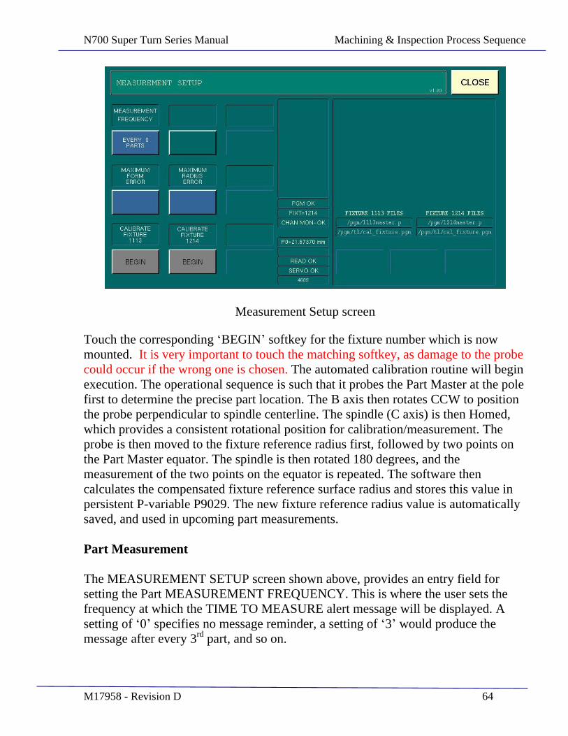
Measurement Setup screen
Touch the corresponding BEGIN softkey for the fixture number which is now mounted. It is very important to touch the matching softkey, as damage to the probe could occur if the wrong one is chosen. The automated calibration routine will begin execution. The operational sequence is such that it probes the Part Master at the pole first to determine the precise part location. The B axis then rotates CCW to position the probe perpendicular to spindle centerline. The spindle (C axis) is then Homed, which provides a consistent rotational position for calibration/measurement. The probe is then moved to the fixture reference radius first, followed by two points on the Part Master equator. The spindle is then rotated 180 degrees, and the measurement of the two points on the equator is repeated. The software then calculates the compensated fixture reference surface radius and stores this value in persistent P-variable P9029. The new fixture reference radius value is automatically saved, and used in upcoming part measurements.
Part Measurement
The MEASUREMENT SETUP screen shown above, provides an entry field for setting the Part MEASUREMENT FREQUENCY. This is where the user sets the frequency at which the TIME TO MEASURE alert message will be displayed. A setting of 0 specifies no message reminder, a setting of 3 would produce the message after every 3rd part, and so on.
N700 Super Turn Series Manual Machining & Inspection Process Sequence
M17958 - Revision D 65
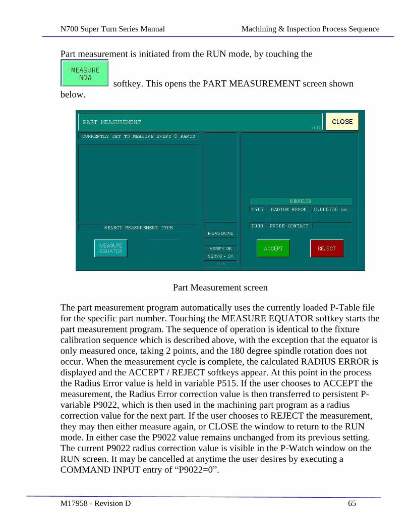
Part measurement is initiated from the RUN mode, by touching the
softkey. This opens the PART MEASUREMENT screen shown below.
Part Measurement screen
The part measurement program automatically uses the currently loaded P-Table file for the specific part number. Touching the MEASURE EQUATOR softkey starts the part measurement program. The sequence of operation is identical to the fixture calibration sequence which is described above, with the exception that the equator is only measured once, taking 2 points, and the 180 degree spindle rotation does not occur. When the measurement cycle is complete, the calculated RADIUS ERROR is displayed and the ACCEPT / REJECT softkeys appear. At this point in the process the Radius Error value is held in variable P515. If the user chooses to ACCEPT the measurement, the Radius Error correction value is then transferred to persistent P-variable P9022, which is then used in the machining part program as a radius correction value for the next part. If the user chooses to REJECT the measurement, they may then either measure again, or CLOSE the window to return to the RUN mode. In either case the P9022 value remains unchanged from its previous setting. The current P9022 radius correction value is visible in the P-Watch window on the RUN screen. It may be cancelled at anytime the user desires by executing a COMMAND INPUT entry of P9022=0 .
N700 Super Turn Series Manual Machining & Inspection Process Sequence
M17958 - Revision D 66
N700 Super Turn Series Manual Machining & Inspection Process Sequence
M17958 - Revision D 67
N700 Super Turn Series Manual Machining & Inspection Process Sequence
M17958 - Revision D 68
N700 Super Turn Series Manual Tool Change Process
M17958 - Revision D 69
SECTION 9
Tool Change Process
N700 Super Turn Series Manual Tool Change Process
M17958 - Revision D 70
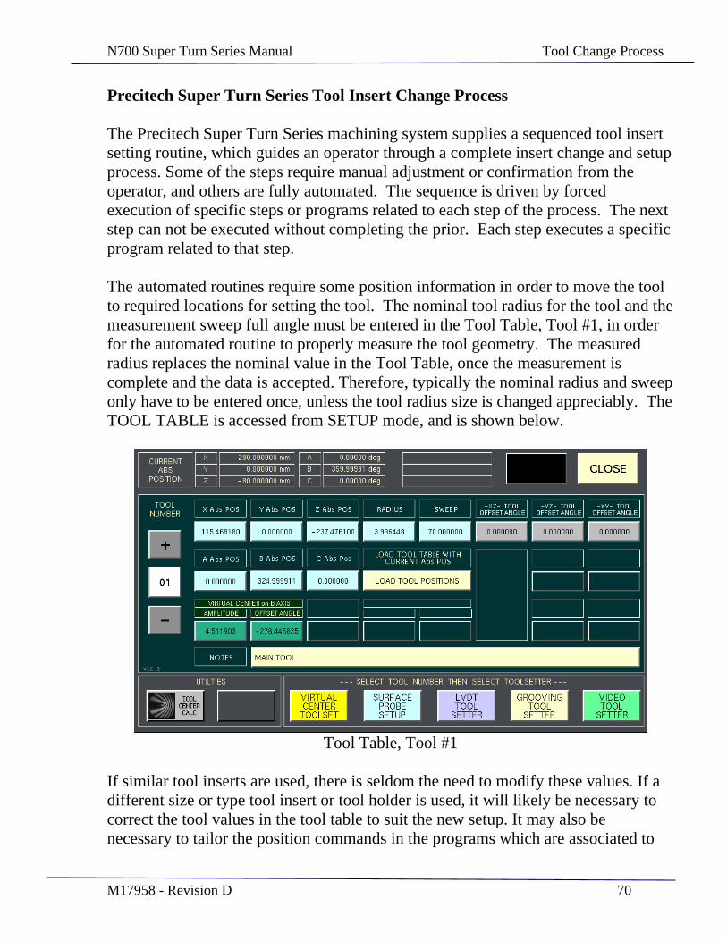
Precitech Super Turn Series Tool Insert Change Process
The Precitech Super Turn Series machining system supplies a sequenced tool insert setting routine, which guides an operator through a complete insert change and setup process. Some of the steps require manual adjustment or confirmation from the operator, and others are fully automated. The sequence is driven by forced execution of specific steps or programs related to each step of the process. The next step can not be executed without completing the prior. Each step executes a specific program related to that step.
The automated routines require some position information in order to move the tool to required locations for setting the tool. The nominal tool radius for the tool and the measurement sweep full angle must be entered in the Tool Table, Tool #1, in order for the automated routine to properly measure the tool geometry. The measured radius replaces the nominal value in the Tool Table, once the measurement is complete and the data is accepted. Therefore, typically the nominal radius and sweep only have to be entered once, unless the tool radius size is changed appreciably. The TOOL TABLE is accessed from SETUP mode, and is shown below.
Tool Table, Tool #1
If similar tool inserts are used, there is seldom the need to modify these values. If a different size or type tool insert or tool holder is used, it will likely be necessary to correct the tool values in the tool table to suit the new setup. It may also be necessary to tailor the position commands in the programs which are associated to
N700 Super Turn Series Manual Tool Change Process
M17958 - Revision D 71
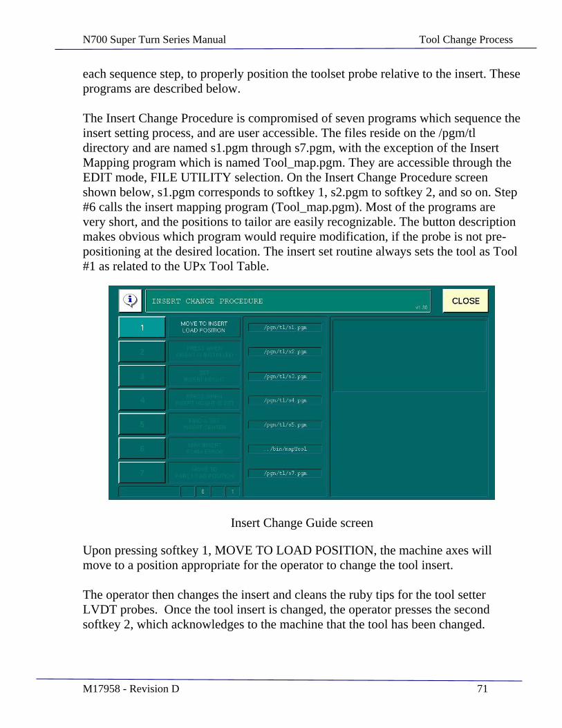
each sequence step, to properly position the toolset probe relative to the insert. These programs are described below.
The Insert Change Procedure is compromised of seven programs which sequence the insert setting process, and are user accessible. The files reside on the /pgm/tl directory and are named s1.pgm through s7.pgm, with the exception of the Insert Mapping program which is named Tool_map.pgm. They are accessible through the EDIT mode, FILE UTILITY selection. On the Insert Change Procedure screen shown below, s1.pgm corresponds to softkey 1, s2.pgm to softkey 2, and so on. Step #6 calls the insert mapping program (Tool_map.pgm). Most of the programs are very short, and the positions to tailor are easily recognizable. The button description makes obvious which program would require modification, if the probe is not pre-positioning at the desired location. The insert set routine always sets the tool as Tool #1 as related to the UPx Tool Table.
Insert Change Guide screen
Upon pressing softkey 1, MOVE TO LOAD POSITION, the machine axes will move to a position appropriate for the operator to change the tool insert.
The operator then changes the insert and cleans the ruby tips for the tool setter LVDT probes. Once the tool insert is changed, the operator presses the second softkey 2, which acknowledges to the machine that the tool has been changed.

N700 Super Turn Series Manual Tool Change Process
M17958 - Revision D 72
Upon pressing softkey 3, SET TOOL HEIGHT, the vertical LVDT probe is automatically raised and the machine axes move to place the tool tip under the probe. Once in position, the LVDT is lowered and a measurement is taken.
The operator is then responsible for adjusting the tool height until the measured value is 0.0 +/- 0.005 mm. Once in position the operator presses softkey 4, to acknowledge the insert height is now set.
The softkey 5 will command the slides to perform a tool set of the newly installed insert. The screen below shows the results of this automated insert set routine.
Results of finding the Insert center and radius
The operator reviews the results, and then touches the DONE softkey. They must then choose to accept the results or reject the data. If rejected, the newly measured data is discarded and the tool data for tool #1 is left unchanged. If accepted, the tool data for tool #1 is updated and the previous data is discarded. The softkey 6 opens the insert mapping screen, which is shown below.
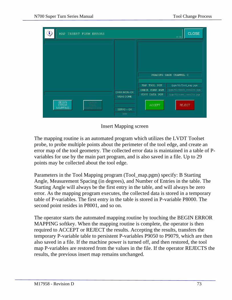
N700 Super Turn Series Manual Tool Change Process
M17958 - Revision D 73
Insert Mapping screen
The mapping routine is an automated program which utilizes the LVDT Toolset probe, to probe multiple points about the perimeter of the tool edge, and create an error map of the tool geometry. The collected error data is maintained in a table of P-variables for use by the main part program, and is also saved in a file. Up to 29 points may be collected about the tool edge.
Parameters in the Tool Mapping program (Tool_map.pgm) specify: B Starting Angle, Measurement Spacing (in degrees), and Number of Entries in the table. The Starting Angle will always be the first entry in the table, and will always be zero error. As the mapping program executes, the collected data is stored in a temporary table of P-variables. The first entry in the table is stored in P-variable P8000. The second point resides in P8001, and so on.
The operator starts the automated mapping routine by touching the BEGIN ERROR MAPPING softkey. When the mapping routine is complete, the operator is then required to ACCEPT or REJECT the results. Accepting the results, transfers the temporary P-variable table to persistent P-variables P9050 to P9079, which are then also saved in a file. If the machine power is turned off, and then restored, the tool map P-variables are restored from the values in the file. If the operator REJECTS the results, the previous insert map remains unchanged.
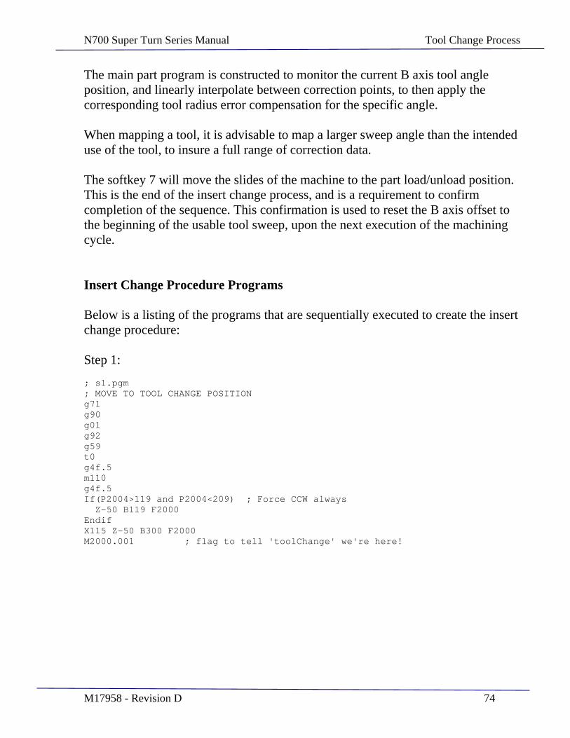
N700 Super Turn Series Manual Tool Change Process
M17958 - Revision D 74
The main part program is constructed to monitor the current B axis tool angle position, and linearly interpolate between correction points, to then apply the corresponding tool radius error compensation for the specific angle.
When mapping a tool, it is advisable to map a larger sweep angle than the intended use of the tool, to insure a full range of correction data.
The softkey 7 will move the slides of the machine to the part load/unload position. This is the end of the insert change process, and is a requirement to confirm completion of the sequence. This confirmation is used to reset the B axis offset to the beginning of the usable tool sweep, upon the next execution of the machining cycle.
Insert Change Procedure Programs
Below is a listing of the programs that are sequentially executed to create the insert change procedure:
Step 1:
; s1.pgm ; MOVE TO TOOL CHANGE POSITION g71 g90 g01 g92 g59 t0 g4f.5 m110 g4f.5 If(P2004>119 and P2004<209) ; Force CCW always Z-50 B119 F2000 Endif X115 Z-50 B300 F2000 M2000.001 ; flag to tell 'toolChange' we're here!

N700 Super Turn Series Manual Tool Change Process
M17958 - Revision D 75
Step 2:
;s2.pgm ;TOOL CHANGE IS COMPLETE (Confirms step 1 only) g71 g90 g01 g92 g59 t0 M18 g4f1 m2000.002 ; flag to tell 'toolChange' we're here
Step 3:
;s3.pgm ; SET TOOL HEIGHT g71 g90 g01 g92 g59 t0 M18 m75.1 ;sync the probe read If(P2012<.05) ;probe didn't raise? P579=4 ;set error code exit Endif
x255.2 z-231.73 b0 F2000 m17 ;lower probe onto tool g4f0.5 m2000.003 ; flag to tell toolChange we're finished
Step 4:
;s4.pgm ; CONFIRM HEIGHT SET & RAISE LVDT t0 g4f1 m18 ;raise LVDT m2000.004
N700 Super Turn Series Manual Tool Change Process
M17958 - Revision D 76
Step 5:
;s5.pgm ; DO LVDT TOOLSET g71 g90 g01 g92 g59 t0 M75.1 If(P2012<.5) ; vertical probe didn't raise P579=4 ; set error code exit Endif
z-220 f500 x276.441 z-229.44 b-35 g4f1 M2000.027 ; calls the toolset routine P9025=1 ; flag to pgm that tool is changed P9022=0 ; clear radius offset from equator error g4f1 m2000.005 ; flag to tell toolChange we're finished
Step 6:
;Tool_map.pgm 10/22/2009
;Program to measure multiple points about the perimeter of the tool, ;and map tool waviness and virtual center errors.
;This runs as sequence number 6 in the TOOL CHANGE GUIDE.
P41=1 ;fixture = ok
;watch:P8000=1st point W ;watch:P8001=2nd point W ;watch:P8002=3rd point W ;watch:P8003=4th point W ;watch:P8004=5th point W ;watch:P8005=6th point W ;watch:P8006=7th point W ;watch:P8007=8th point W ;watch:P8008=9th point W ;watch:P8009=10th point W ;watch:P8010=11th point W ;watch:P8011=12th point W ;watch:P8012=13th point W ;watch:P8013=14th point W ;watch:P8014=15th point W ;watch:P41=fixture status
;---------------------- Setup Parameters ----------------------------
N700 Super Turn Series Manual Tool Change Process
M17958 - Revision D 77
P600=-35 ;Starting B angle @ X0 Z0 (degrees) P9032=5 ;Measurement increment (degrees) P603=19 ;Number of P-vars in the array
;---------------- Internal Program variables ------------------------
P610=P600 ;current B angle = starting angle ;P611= ;current W value P612=0 ;array index for p-var number assignment ;P613= ;point counter ;P614= ;W offset to make 1st point = 0 correction ;P615= ;calculated Z @ probe null position
;---------------------- Main Program -------------------------------- P560=0 ;Program status = started
If(P603>29) P579=8 ;ERROR = TOO MANY POINTS P560=-1 ;Program status = Done & error EXIT ;Abort if specified # of points > 29 Endif
G90 ;Absolute mode G01 ;linear G59 ;clear all programmable offsets G92 ;clear all G92 Presets T1 ;Mapped tool is always T1 M110.1 ;Get the lvdt probe X offset & Probe radius
Z50 F1000 X(-P2006) B(P610) F500 ;X to Tset LVDT X Offset
P615=P590+P2007 ;Z null = Tool rad + probe radius Z(P615+5) F1000 ;move to clearance position
While(P612<P603) ;Loop for specified number of points
Z(P615+2) F300 ;Z to 2mm off from probe null G04 F.5 B(P610) F1000 ;move B to the next mapping point Z(P615) F100 ;move Z/tool to ~probe nullposition G04 F1.5 ;wait for 1.5 seconds for things to settle M75.1 ;get the analog probe value
If(P612=0) ;if it's the 1st point in the map P614=P2011 ;store the W offset for the first point P8000=0 ;1st pt correction value = 0.0 Else P(8000+P612)=P2011-P614 ;store the probe W reading - W offset Endif
P610=P610+P9032 ;increment the B angle P612=P612+1 ;increment the array index
Endwhile
Z100 F1000 ;Z to safe retract
N700 Super Turn Series Manual Tool Change Process
M17958 - Revision D 78
G04 F.5 P560=1 ;Program status = done & valid
M2000.006 ;tells the host that Toolset seq #6 is done
Step 7:
;s7.pgm ; GO TO PART LOAD POSITION g71 g90 g01 g92 g59 t0 P579=0 ; clear tool change required error code P9025=1 ; flag to pgm that tool is changed P9022=0 ; clear radius offset from equator error x280 z-50 f2000 m2000.007 ; flag to say we're finished
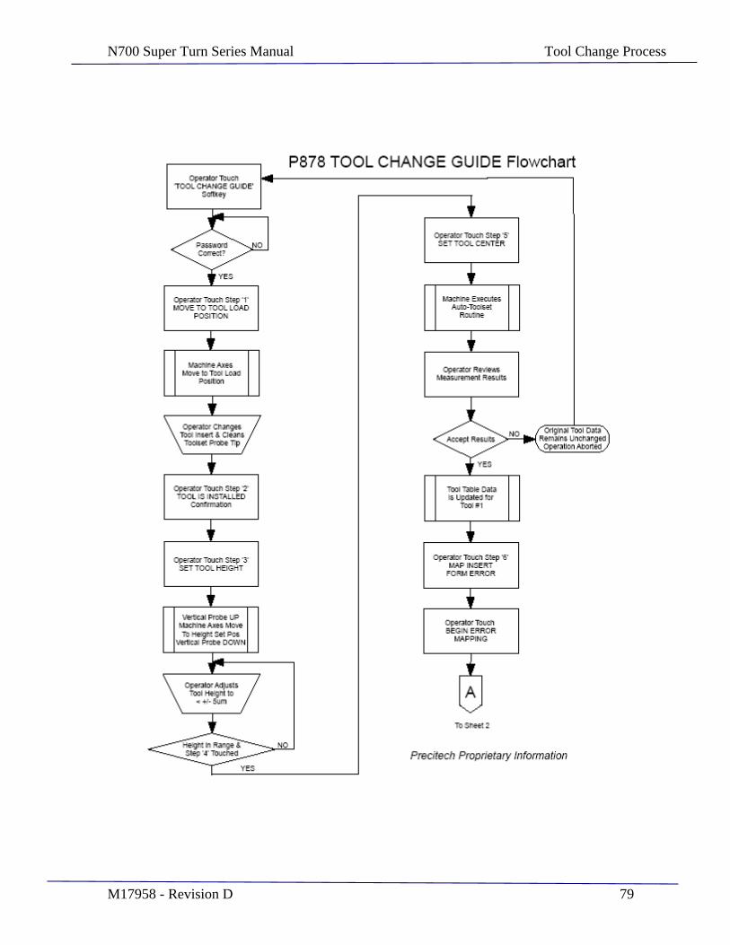
N700 Super Turn Series Manual Tool Change Process
M17958 - Revision D 79

N700 Super Turn Series Manual Tool Change Process
M17958 - Revision D 80
N700 Super Turn Series Manual Program Printouts
M17958 - Revision D 81
SECTION 10
Program File Printouts

N700 Super Turn Series Manual Program Printouts
M17958 - Revision D 82
Name and File Locations Description
In the /pgm directory: P915.pgm Main Paramacro program surface.probe Surface/Part Probing program flat.pgm Part program for cutting a Flat.
Used for Surface probe calibration 17rcx.pgm Part program for cutting a 17mm convex radius.
Used for Toolset probe calibration P579error.codes Text file which specifies the error message
related to the P579 error code number part_data.p The machine resident P-Table file.
The scanned job P-table gets copied to here. 1113master.p P-table for 1113 Part Master 1214master.p P-table for 1214 Part Master
In the /pgm/tl directory: s1.pgm "Move To Insert Load Position" program s2.pgm "Press When Insert Is Installed" program s3.pgm "Set Insert Height" program s4.pgm "Press When Tool Height Is Set" program s5.pgm "Set Insert Center" program s7.pgm "Move To Part Load Position" program m1.pgm Equator Measurement Program cal_fixture.pgm Fixture Calibration Program Tool_Map.pgm Tool Mapping Program check_results.pgm Program to check Tool Map Corrections save_results.pgm Program to save data when prompted by operator
/upx.setup/autop_cfg.dat Configuration File for automated network communications (Bar Code Scanner file selection)

N700 Super Turn Series Manual Program Printouts
M17958 - Revision D 83
P915.pgm Main Paramacro program
;P915.pgm 04/28/2010 ;Precitech Proprietary Information ;Similiar to P878.pgm, with the following modifications. ; 1. Remaining tool sweep (P9021) is now calculated based ; on P9020, which is the current B/Tool offset. ; 2. P5 was added to the watch window, and the unused ; measurement variables P9022, P9029, P502, P515 removed. ; 3. P28, P29 added to define a blend zone between the toric ; and the sphere to avoid instantaneous b-motion ; P562, P563, P564 also added to do the blend zone calcs ; 4. During path generation, P575 is now incremented at the ; end of the loop, not the beginning ; 5. P6 is added as a "material on" variable that basically ; is a tool radius offset. P2 and P3, the spherical and ; toric radii will now be the finished part dimensions; ; the path will be the finished path, but the P6 offset ; will mean that there will be P6 "material on" the part ; which will then be taken off in subsequent polishing ; operations ; 6. P33 and P34 are the angles before and after the toric ; that define the width of the equator correction zone ; P35 is the hieght of the equator correction which ramps ; up from zero at P33 degrees before the equator, reaches ; a maximum of P35 material on at the equator, and ramps ; down to zero again at P34 degrees after the equator. ; P34 cannot be so big that the equator correction zone ; extends into the spherical or blend part of the surface ; as the zone will end immediately if the toric while loop ; is exited (P34<40 deg)
;Z=tool radius (P1) when the tool is touching at the pole of ;the finished turned part
;NOTE: The Part and Machining Parameters shown below are ;loaded from a 'P' table file. The values shown are typical ;and for reference only.
;------------------ Part Parameters ------------------------
;Below is a list of p-table parameters to be used for reference ;the actual values used by the program will be taken from the ;p-table
;P2=18.0350 ;Finished Spherical radius ;P3=18.0120 ;Finished Toric radius ;P4=0.01549 ;Toric center X offset ;P5=0.0015 ;Start of toric correction value ;p6=0.0025 ;"material on" offset, the part will have this
;much material left to be polished off ;p7=133.1 ;Starting angle of the Toric ;P8=47.5 ;Starting angle of the sphere ;P9=0.05 ;.05 Angular increment
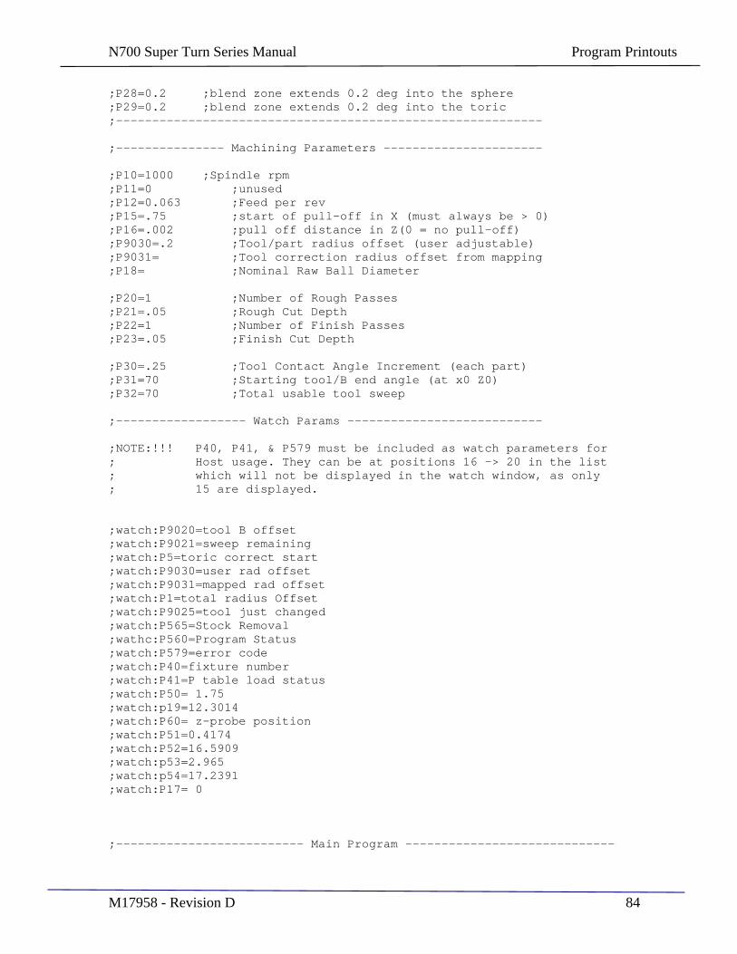
N700 Super Turn Series Manual Program Printouts
M17958 - Revision D 84
;P28=0.2 ;blend zone extends 0.2 deg into the sphere ;P29=0.2 ;blend zone extends 0.2 deg into the toric ;-----------------------------------------------------------
;--------------- Machining Parameters ----------------------
;P10=1000 ;Spindle rpm ;P11=0 ;unused ;P12=0.063 ;Feed per rev ;P15=.75 ;start of pull-off in X (must always be > 0) ;P16=.002 ;pull off distance in Z(0 = no pull-off) ;P9030=.2 ;Tool/part radius offset (user adjustable) ;P9031= ;Tool correction radius offset from mapping ;P18= ;Nominal Raw Ball Diameter
;P20=1 ;Number of Rough Passes ;P21=.05 ;Rough Cut Depth ;P22=1 ;Number of Finish Passes ;P23=.05 ;Finish Cut Depth
;P30=.25 ;Tool Contact Angle Increment (each part) ;P31=70 ;Starting tool/B end angle (at x0 Z0) ;P32=70 ;Total usable tool sweep
;------------------ Watch Params ---------------------------
;NOTE:!!! P40, P41, & P579 must be included as watch parameters for ; Host usage. They can be at positions 16 -> 20 in the list ; which will not be displayed in the watch window, as only ; 15 are displayed.
;watch:P9020=tool B offset ;watch:P9021=sweep remaining ;watch:P5=toric correct start ;watch:P9030=user rad offset ;watch:P9031=mapped rad offset ;watch:P1=total radius Offset ;watch:P9025=tool just changed ;watch:P565=Stock Removal ;wathc:P560=Program Status ;watch:P579=error code ;watch:P40=fixture number ;watch:P41=P table load status ;watch:P50= 1.75 ;watch:p19=12.3014 ;watch:P60= z-probe position ;watch:P51=0.4174 ;watch:P52=16.5909 ;watch:p53=2.965 ;watch:p54=17.2391 ;watch:P17= 0
;-------------------------- Main Program -----------------------------
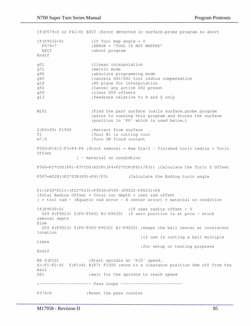
N700 Super Turn Series Manual Program Printouts
M17958 - Revision D 85
If(P579>0 or P41<0) EXIT ;Error detected in surface.probe program so abort
If(P9032=0) ;If Tool map angle = 0 P579=7 ;ERROR = "TOOL IS NOT MAPPED" EXIT ;abort program Endif
g01 ;linear interpolation g71 ;metric mode g90 ;absolute programming mode g40 ;cancels G41/G42 tool radius compensation g18 ;XZ plane for interpolation g92 ;Cancel any active G92 preset g59 ;clear G59 offsets g13 ;feedrate relative to X and Z only
M101 ;Find the part surface (calls surface.probe program ;prior to running this program and stores the surface ;position in 'P0' which is used below.)
Z(P0+50) F1500 ;Retract from surface T1 ;Tool #1 is cutting tool m7.5 ;Turn ON flood coolant
P565=P18/2-P3+P4-P6 ;Stock removal = Raw Dia/2 - finished toric radius + Toric Offset
; - material on condidtion
P566=P2*COS(P8)-P3*COS(ASIN((P4+P2*SIN(P8))/P3)) ;Calculate the Toric Z Offset
P567=ASIN((P2*SIN(P8)+P4)/P3) ;Calculate the Ending toric angle
P1=(P20*P21)+(P22*P23)+P9030+P590-(P9022-P9023)+P6 ;Total Radius Offset = Total cut depth + user rad offset ; + tool rad - (Equator rad error - X center error) + material on condition
If(P9030>0) ;If user radius offset > 0 G59 X(P9023) Z(P0-P565) B(-P9020) ;Z zero position is at pole - stock removal depth Else G59 X(P9023) Z(P0-P565-P9030) B(-P9020) ;keeps the ball center at consistent location ;if one is cutting a ball multiple
times ;for setup or testing purposes Endif
M4 S(P10) ;Start spindle at 'P10' speed. X(-P1-P2-6) Z(P1+6) B(P7) F1500 ;move to a clearance position 6mm off from the ball G81 ;wait for the spindle to reach speed
;--------------------- Pass Loops -------------------------
P574=0 ;Reset the pass counter
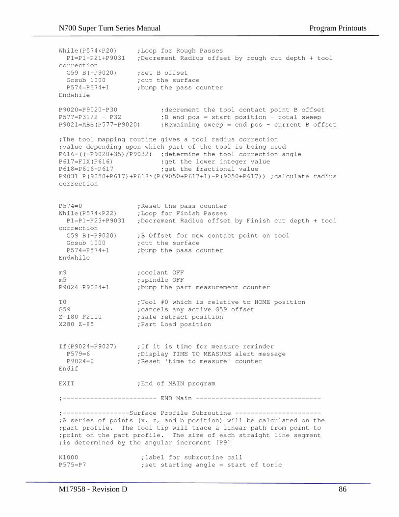
N700 Super Turn Series Manual Program Printouts
M17958 - Revision D 86
While(P574<P20) ;Loop for Rough Passes P1=P1-P21+P9031 ;Decrement Radius offset by rough cut depth + tool correction G59 B(-P9020) ;Set B offset Gosub 1000 ;cut the surface P574=P574+1 ;bump the pass counter Endwhile
P9020=P9020-P30 ;decrement the tool contact point B offset P577=P31/2 - P32 ;B end pos = start position - total sweep P9021=ABS(P577-P9020) ;Remaining sweep = end pos - current B offset
;The tool mapping routine gives a tool radius correction ;value depending upon which part of the tool is being used P616=((-P9020+35)/P9032) ;determine the tool correction angle P617=FIX(P616) ;get the lower integer value P618=P616-P617 ;get the fractional value P9031=P(9050+P617)+P618*(P(9050+P617+1)-P(9050+P617)) ;calculate radius correction
P574=0 ;Reset the pass counter While(P574<P22) ;Loop for Finish Passes P1=P1-P23+P9031 ;Decrement Radius offset by Finish cut depth + tool correction G59 B(-P9020) ;B Offset for new contact point on tool Gosub 1000 ;cut the surface P574=P574+1 ;bump the pass counter Endwhile
m9 ;coolant OFF m5 ;spindle OFF P9024=P9024+1 ;bump the part measurement counter
T0 ;Tool #0 which is relative to HOME position G59 ;cancels any active G59 offset Z-180 F2000 ;safe retract position X280 Z-85 ;Part Load position
If(P9024=P9027) ;If it is time for measure reminder P579=6 ;Display TIME TO MEASURE alert message P9024=0 ;Reset 'time to measure' counter Endif
EXIT ;End of MAIN program
;------------------------ END Main --------------------------------
;-----------------Surface Profile Subroutine ---------------------- ;A series of points (x, z, and b position) will be calculated on the ;part profile. The tool tip will trace a linear path from point to ;point on the part profile. The size of each straight line segment ;is determined by the angular increment [P9]
N1000 ;label for subroutine call P575=P7 ;set starting angle = start of toric
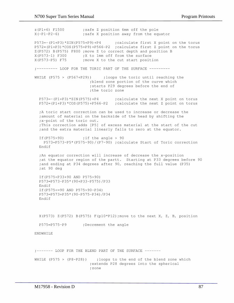
N700 Super Turn Series Manual Program Printouts
M17958 - Revision D 87
z(P1+6) F1500 ;safe Z position 6mm off the pole X(-P1-P2-6) ;safe X position away from the equator
P573=-(P1+P3)*SIN(P575+P9)+P4 ;calculate first X point on the torus P572=(P1+P3)*COS(P575+P9)+P566-P2 ;calculate first Z point on the torus Z(P572) B(P575) F800 ;move Z to correct depth and position B X(P573-1) F300 ;X to 1mm off from the surface X(P573-P5) F75 ;move X to the cut start position
;--------- LOOP FOR THE TORIC PART OF THE SURFACE ---------
WHILE (P575 > (P567+P29)) ;loops the toric until reaching the ;blend zone portion of the curve which ;starts P29 degrees before the end of ;the toric zone
P573=-(P1+P3)*SIN(P575)+P4 ;calculate the next X point on torus P572=(P1+P3)*COS(P575)+P566-P2 ;calculate the next Z point on torus
;A toric start correction can be used to increase or decrease the ;amount of material on the backside of the head by shifting the ;x-point of the toric out. ;This correction adds [P5] of excess material at the start of the cut ;and the extra material linearly falls to zero at the equator.
If(P575>90) ;if the angle > 90 P573=P573-P5*(P575-90)/(P7-90) ;calculate Start of Toric correction Endif
;An equator correction will increase of decrease the x-position ;at the equator region of the partt. Starting at P33 degrees before 90 ;and ending at P34 degrees after 90, reaching the full value (P35) ;at 90 deg If(P575<P33+90 AND P575>90) P573=P573-P35*(90+P33-P575)/P33 Endif If(P575<=90 AND P575>90-P34) P573=P573+P35*(90-P575-P34)/P34 Endif
X(P573) Z(P572) B(P575) F(p10*P12);move to the next X, Z, B, position
P575=P575-P9 ;Decrement the angle
ENDWHILE
;------- LOOP FOR THE BLEND PART OF THE SURFACE -------
WHILE (P575 > (P8-P28)) ;loops to the end of the blend zone which ;extends P28 degrees into the spherical ;zone
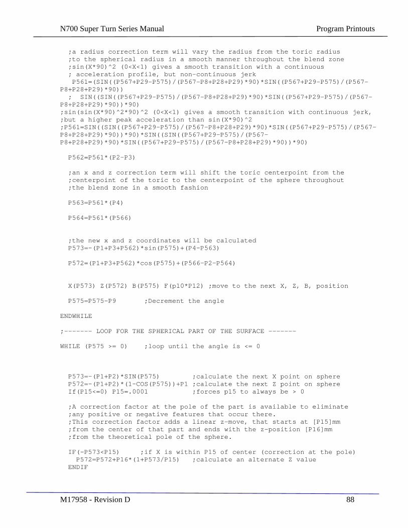
N700 Super Turn Series Manual Program Printouts
M17958 - Revision D 88
;a radius correction term will vary the radius from the toric radius ;to the spherical radius in a smooth manner throughout the blend zone ;sin(X*90)^2 (0<X<1) gives a smooth transition with a continuous ; acceleration profile, but non-continuous jerk P561=(SIN((P567+P29-P575)/(P567-P8+P28+P29)*90)*SIN((P567+P29-P575)/(P567-P8+P28+P29)*90)) ; SIN((SIN((P567+P29-P575)/(P567-P8+P28+P29)*90)*SIN((P567+P29-P575)/(P567-P8+P28+P29)*90))*90) ;sin(sin(X*90)^2*90)^2 (0<X<1) gives a smooth transition with continuous jerk, ;but a higher peak acceleration than sin(X*90)^2 ;P561=SIN((SIN((P567+P29-P575)/(P567-P8+P28+P29)*90)*SIN((P567+P29-P575)/(P567-P8+P28+P29)*90))*90)*SIN((SIN((P567+P29-P575)/(P567-P8+P28+P29)*90)*SIN((P567+P29-P575)/(P567-P8+P28+P29)*90))*90) P562=P561*(P2-P3)
;an x and z correction term will shift the toric centerpoint from the ;centerpoint of the toric to the centerpoint of the sphere throughout ;the blend zone in a smooth fashion
P563=P561*(P4)
P564=P561*(P566)
;the new x and z coordinates will be calculated P573=-(P1+P3+P562)*sin(P575)+(P4-P563)
P572=(P1+P3+P562)*cos(P575)+(P566-P2-P564)
X(P573) Z(P572) B(P575) F(p10*P12) ;move to the next X, Z, B, position
P575=P575-P9 ;Decrement the angle
ENDWHILE
;------- LOOP FOR THE SPHERICAL PART OF THE SURFACE -------
WHILE (P575 >= 0) ;loop until the angle is <= 0
P573=-(P1+P2)*SIN(P575) ;calculate the next X point on sphere P572=-(P1+P2)*(1-COS(P575))+P1 ;calculate the next Z point on sphere If(P15<=0) P15=.0001 ;forces p15 to always be > 0
;A correction factor at the pole of the part is available to eliminate ;any positive or negative features that occur there. ;This correction factor adds a linear z-move, that starts at [P15]mm ;from the center of that part and ends with the z-position [P16]mm ;from the theoretical pole of the sphere.
IF(-P573<P15) ;if X is within P15 of center (correction at the pole) P572=P572+P16*(1+P573/P15) ;calculate an alternate Z value ENDIF

N700 Super Turn Series Manual Program Printouts
M17958 - Revision D 89
X(P573) Z(P572) B(P575) F(p10*P12) ;move to the next X, Z, B, position
P575=P575-P9 ;Decrement the angle
ENDWHILE
X0 Z(P1+6) F700 ;move 6mm off from the pole P570=(P9020+P31/2) ;calculate B ABS 0 adjusted by g59 offset B(P570) F1500 ;move B to ABS 0.0
RET ;return to main program
;----------------- END Surface Profile Subroutine --------------------
surface.probe Surface/Part Probing program
; surface.probe 10/06/2009 ; Surface Probing routine for P878 hard turning ; The setup paramters below MUST be configured to the specific ; machine setup for each of two fixtures. ; ;--------------------- Setup Parameters ------------------------ If(P17>0) P50=1.75 ;Probe clearance from null (pre-travel + clearance) Else P50=1.75+P17 ;Probe clearance from null (pre-travel + clearance) Endif P51=.4174 ;1214 Fixture end to reference diameter dimension P52=14.441 ;1214 Tool #8 active, CMD position at fixture end P53=2.965 ;1113 Fixture end to reference diameter dimension P54=17.2391 ;1113 Tool #8 active, CMD position at fixture end
;------------------- Error Checking ------------------------
If(P41<0) EXIT ; P-table loaded but fixture # not confirmed
If(P9025=1) ; Tool has just been changed (set = 1 in s5.pgm) P9020=P31/2 ; Set tool angle to starting end angle @ X0 Z0 P9021=P32 ; Set sweep remaining to total usable sweep P9026=0 ; Reset degrees of tool used up P9025=0 ; clear tool changed flag Endif P579=0 ; clear program error flag If(P9021<P31-P32) ; tool sweep is used up P579=1 ; ERROR = "INSERT CHANGE REQUIRED" EXIT ; Abort program if B offset exceeds max Endif
If(P2=0orP3=0orP4=0orP7=0orP8=0orP18=0) P579=2 ; ERROR = "PART DEFINITION ERROR" EXIT Endif
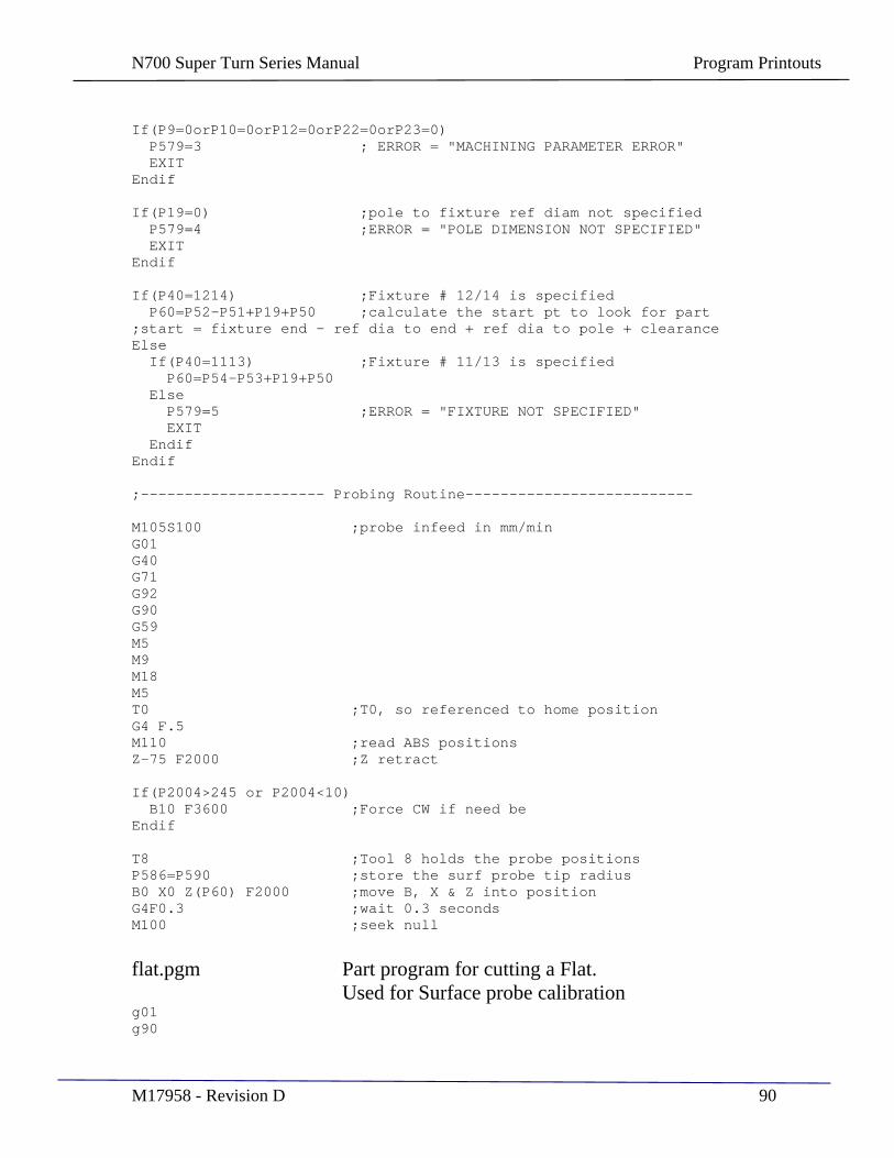
N700 Super Turn Series Manual Program Printouts
M17958 - Revision D 90
If(P9=0orP10=0orP12=0orP22=0orP23=0) P579=3 ; ERROR = "MACHINING PARAMETER ERROR" EXIT Endif
If(P19=0) ;pole to fixture ref diam not specified P579=4 ;ERROR = "POLE DIMENSION NOT SPECIFIED" EXIT Endif
If(P40=1214) ;Fixture # 12/14 is specified P60=P52-P51+P19+P50 ;calculate the start pt to look for part ;start = fixture end - ref dia to end + ref dia to pole + clearance Else If(P40=1113) ;Fixture # 11/13 is specified P60=P54-P53+P19+P50 Else P579=5 ;ERROR = "FIXTURE NOT SPECIFIED" EXIT Endif Endif
;--------------------- Probing Routine--------------------------
M105S100 ;probe infeed in mm/min G01 G40 G71 G92 G90 G59 M5 M9 M18 M5 T0 ;T0, so referenced to home position G4 F.5 M110 ;read ABS positions Z-75 F2000 ;Z retract
If(P2004>245 or P2004<10) B10 F3600 ;Force CW if need be Endif
T8 ;Tool 8 holds the probe positions P586=P590 ;store the surf probe tip radius B0 X0 Z(P60) F2000 ;move B, X & Z into position G4F0.3 ;wait 0.3 seconds M100 ;seek null
flat.pgm Part program for cutting a Flat. Used for Surface probe calibration
g01 g90
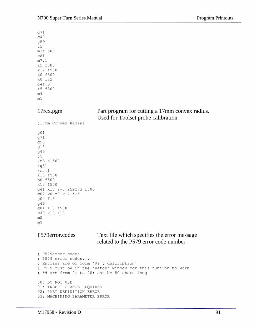
N700 Super Turn Series Manual Program Printouts
M17958 - Revision D 91
g71 g40 g59 t5 m3s1500 g81 m7.1 z5 f300 x12 f500 z0 f300 x0 f25 g4f.5 z5 f300 m9 m5
17rcx.pgm Part program for cutting a 17mm convex radius. Used for Toolset probe calibration
;17mm Convex Radius
g01 g71 g90 g18 g40 t5 /m3 s1500 /g81 /m7.1 z10 f500 b0 f500 x12 f500 g41 x10 z-3.252273 f300 g02 x0 z0 r17 f25 g04 f.5 g46 g01 z10 f500 g40 x10 z10 m5 m9
P579error.codes Text file which specifies the error message related to the P579 error code number
; P579error.codes ; P579 error codes.... ; Entries are of form '##':'description' ; P579 must be in the 'watch' window for this funtion to work ; ## are from 0: to 20: can be 80 chars long
00: DO NOT USE 01: INSERT CHANGE REQUIRED 02: PART DEFINITION ERROR 03: MACHINING PARAMETER ERROR
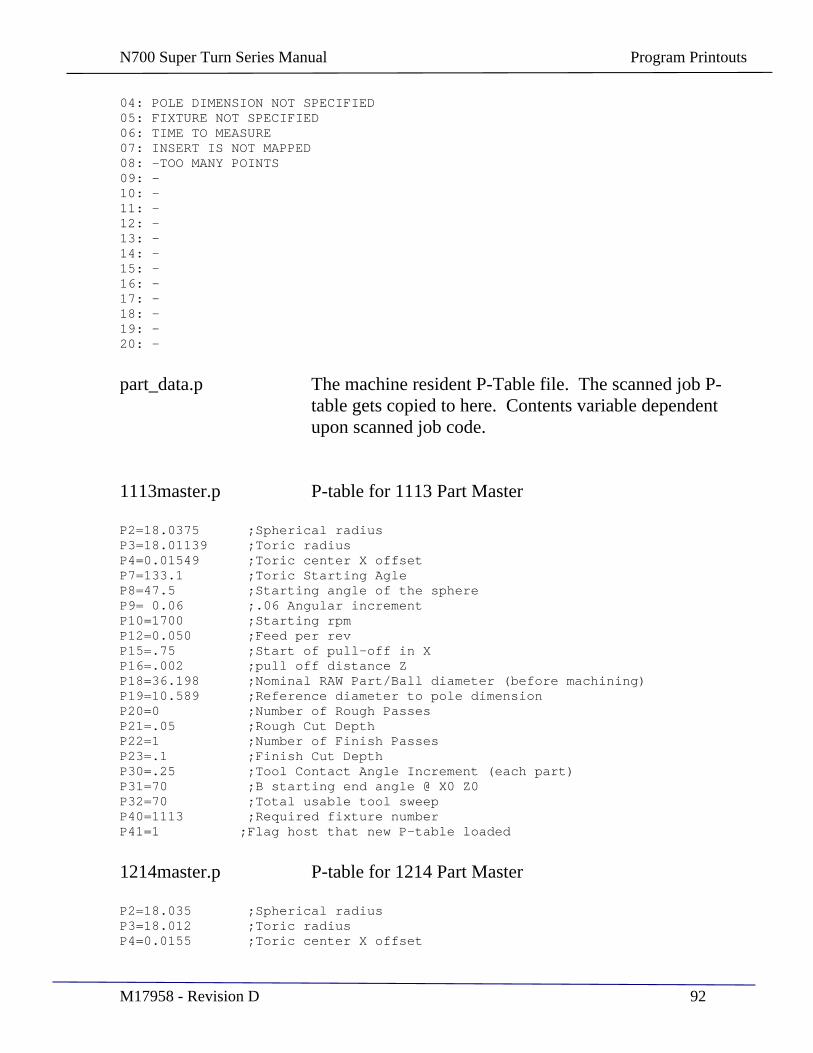
N700 Super Turn Series Manual Program Printouts
M17958 - Revision D 92
04: POLE DIMENSION NOT SPECIFIED 05: FIXTURE NOT SPECIFIED 06: TIME TO MEASURE 07: INSERT IS NOT MAPPED 08: -TOO MANY POINTS 09: - 10: - 11: - 12: - 13: - 14: - 15: - 16: - 17: - 18: - 19: - 20: -
part_data.p The machine resident P-Table file. The scanned job P-table gets copied to here. Contents variable dependent upon scanned job code.
1113master.p P-table for 1113 Part Master
P2=18.0375 ;Spherical radius P3=18.01139 ;Toric radius P4=0.01549 ;Toric center X offset P7=133.1 ;Toric Starting Agle P8=47.5 ;Starting angle of the sphere P9= 0.06 ;.06 Angular increment P10=1700 ;Starting rpm P12=0.050 ;Feed per rev P15=.75 ;Start of pull-off in X P16=.002 ;pull off distance Z P18=36.198 ;Nominal RAW Part/Ball diameter (before machining) P19=10.589 ;Reference diameter to pole dimension P20=0 ;Number of Rough Passes P21=.05 ;Rough Cut Depth P22=1 ;Number of Finish Passes P23=.1 ;Finish Cut Depth P30=.25 ;Tool Contact Angle Increment (each part) P31=70 ;B starting end angle @ X0 Z0 P32=70 ;Total usable tool sweep P40=1113 ;Required fixture number P41=1 ;Flag host that new P-table loaded
1214master.p P-table for 1214 Part Master
P2=18.035 ;Spherical radius P3=18.012 ;Toric radius P4=0.0155 ;Toric center X offset
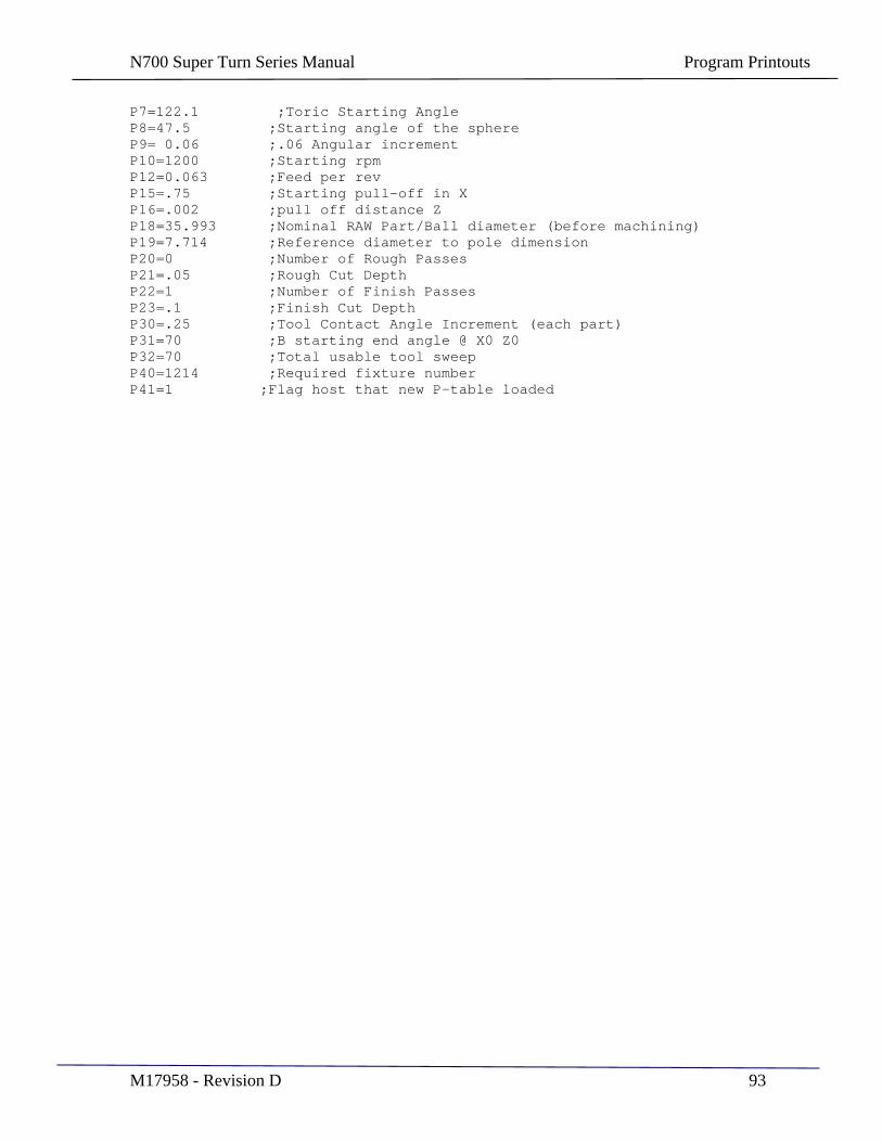
N700 Super Turn Series Manual Program Printouts
M17958 - Revision D 93
P7=122.1 ;Toric Starting Angle P8=47.5 ;Starting angle of the sphere P9= 0.06 ;.06 Angular increment P10=1200 ;Starting rpm P12=0.063 ;Feed per rev P15=.75 ;Starting pull-off in X P16=.002 ;pull off distance Z P18=35.993 ;Nominal RAW Part/Ball diameter (before machining) P19=7.714 ;Reference diameter to pole dimension P20=0 ;Number of Rough Passes P21=.05 ;Rough Cut Depth P22=1 ;Number of Finish Passes P23=.1 ;Finish Cut Depth P30=.25 ;Tool Contact Angle Increment (each part) P31=70 ;B starting end angle @ X0 Z0 P32=70 ;Total usable tool sweep P40=1214 ;Required fixture number P41=1 ;Flag host that new P-table loaded
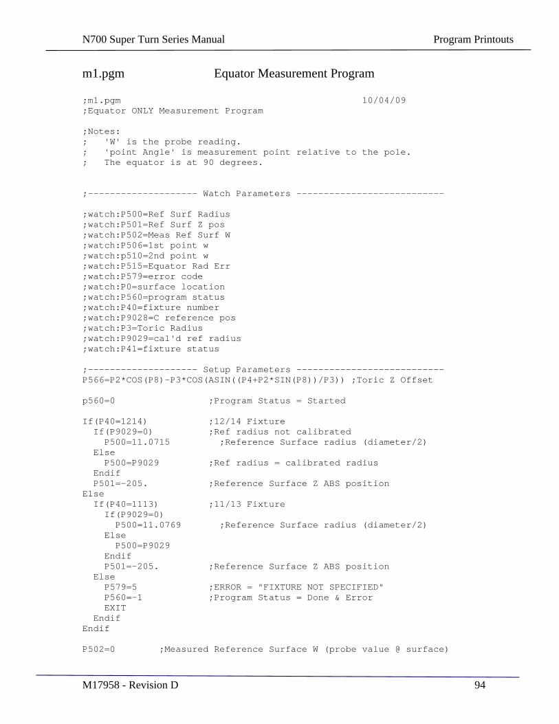
N700 Super Turn Series Manual Program Printouts
M17958 - Revision D 94
m1.pgm Equator Measurement Program
;m1.pgm 10/04/09 ;Equator ONLY Measurement Program
;Notes: ; 'W' is the probe reading. ; 'point Angle' is measurement point relative to the pole. ; The equator is at 90 degrees.
;-------------------- Watch Parameters ---------------------------
;watch:P500=Ref Surf Radius ;watch:P501=Ref Surf Z pos ;watch:P502=Meas Ref Surf W ;watch:P506=1st point w ;watch:p510=2nd point w ;watch:P515=Equator Rad Err ;watch:P579=error code ;watch:P0=surface location ;watch:P560=program status ;watch:P40=fixture number ;watch:P9028=C reference pos ;watch:P3=Toric Radius ;watch:P9029=cal'd ref radius ;watch:P41=fixture status
;-------------------- Setup Parameters --------------------------- P566=P2*COS(P8)-P3*COS(ASIN((P4+P2*SIN(P8))/P3)) ;Toric Z Offset
p560=0 ;Program Status = Started
If(P40=1214) ;12/14 Fixture If(P9029=0) ;Ref radius not calibrated P500=11.0715 ;Reference Surface radius (diameter/2) Else P500=P9029 ;Ref radius = calibrated radius Endif P501=-205. ;Reference Surface Z ABS position Else If(P40=1113) ;11/13 Fixture If(P9029=0) P500=11.0769 ;Reference Surface radius (diameter/2) Else P500=P9029 Endif P501=-205. ;Reference Surface Z ABS position Else P579=5 ;ERROR = "FIXTURE NOT SPECIFIED" P560=-1 ;Program Status = Done & Error EXIT Endif Endif
P502=0 ;Measured Reference Surface W (probe value @ surface)
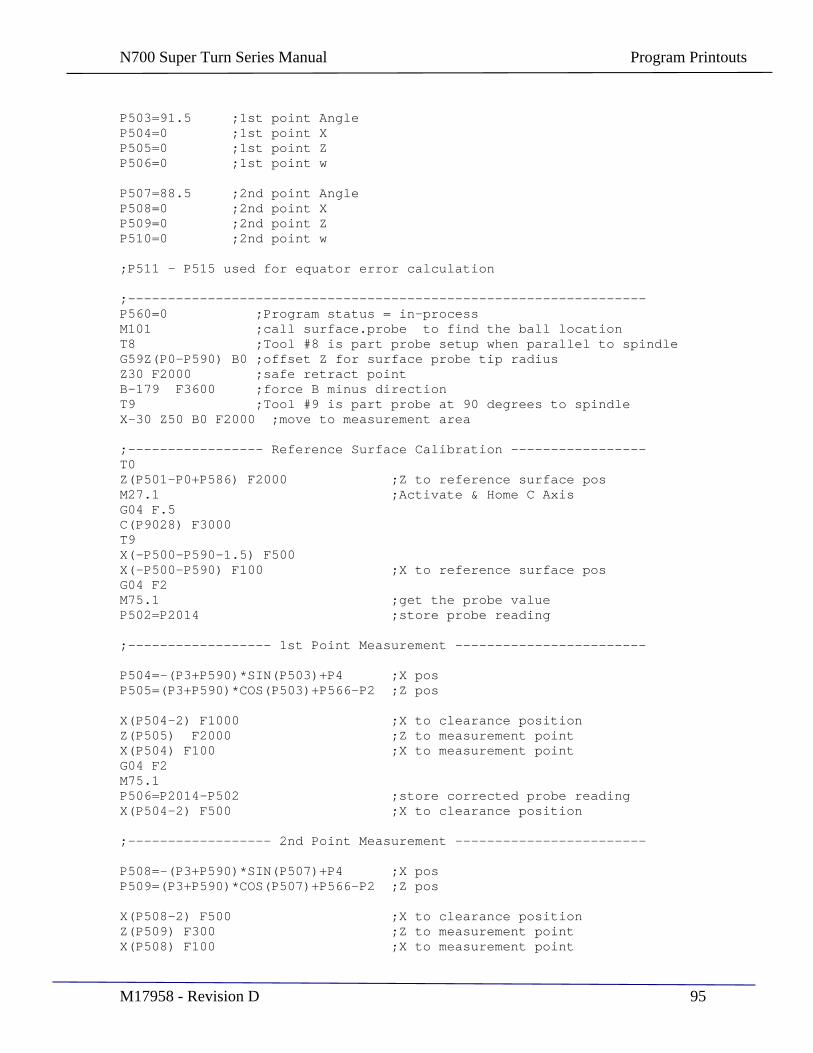
N700 Super Turn Series Manual Program Printouts
M17958 - Revision D 95
P503=91.5 ;1st point Angle P504=0 ;1st point X P505=0 ;1st point Z P506=0 ;1st point w
P507=88.5 ;2nd point Angle P508=0 ;2nd point X P509=0 ;2nd point Z P510=0 ;2nd point w
;P511 - P515 used for equator error calculation
;----------------------------------------------------------------- P560=0 ;Program status = in-process M101 ;call surface.probe to find the ball location T8 ;Tool #8 is part probe setup when parallel to spindle G59Z(P0-P590) B0 ;offset Z for surface probe tip radius Z30 F2000 ;safe retract point B-179 F3600 ;force B minus direction T9 ;Tool #9 is part probe at 90 degrees to spindle X-30 Z50 B0 F2000 ;move to measurement area
;----------------- Reference Surface Calibration ----------------- T0 Z(P501-P0+P586) F2000 ;Z to reference surface pos M27.1 ;Activate & Home C Axis G04 F.5 C(P9028) F3000 T9 X(-P500-P590-1.5) F500 X(-P500-P590) F100 ;X to reference surface pos G04 F2 M75.1 ;get the probe value P502=P2014 ;store probe reading
;------------------ 1st Point Measurement ------------------------
P504=-(P3+P590)*SIN(P503)+P4 ;X pos P505=(P3+P590)*COS(P503)+P566-P2 ;Z pos
X(P504-2) F1000 ;X to clearance position Z(P505) F2000 ;Z to measurement point X(P504) F100 ;X to measurement point G04 F2 M75.1 P506=P2014-P502 ;store corrected probe reading X(P504-2) F500 ;X to clearance position
;------------------ 2nd Point Measurement ------------------------
P508=-(P3+P590)*SIN(P507)+P4 ;X pos P509=(P3+P590)*COS(P507)+P566-P2 ;Z pos
X(P508-2) F500 ;X to clearance position Z(P509) F300 ;Z to measurement point X(P508) F100 ;X to measurement point

N700 Super Turn Series Manual Program Printouts
M17958 - Revision D 96
G04 F2 M75.1 P510=P2014-P502 ;store corrected probe reading X(P508-5) F1000 ;X to clearance position
Z25 F2000 Z85 B90 C355 ;move to retract position M26 ;Back to RPM mode
;---------------- Calculate Equator Error -----------------------
P511=-P509+P505 ;delta Z P512=-P510+P508+P506-P504 ;delta W-X P513=P511*P511 + P512*P512 ;length squared P514=SQRT((P3+P590)*(P3+P590)/P513 - 0.25) P515=0.5*(P510-P508+P506-P504) + P511*P514 + P4 ;equator radius error
G04 F.5 P560=1 ;Program Status = done & valid
cal_fixture.pgm Fixture Calibration Program
;cal_fixture.pgm 10/08/09
;Calibration routine that calibrates the fixture reference radius ;using a known part master equator radius. This routine compensates ;for fixture run-out that my occur at installation, and must be run ;everytime a fixture is installed.
;Notes: ; 'W' is the probe reading. ; 'point Angle' is measurement point relative to the pole. ; The equator is at 90 degrees.
;-------------------- Watch Parameters ---------------------------
;watch:P500=Ref Surf Radius ;watch:P501=Ref Surf Z pos ;watch:P502=Meas Ref Surf W ;watch:P506=1st point w ;watch:p510=2nd point w ;watch:P3=toric radius ;watch:P579=error code ;watch:P0=surface location ;watch:P560=program status ;watch:P9028=C reference pos ;watch:P558=1st Equ rad err ;watch:P515=2nd Equ rad error ;watch:P559=Average Rad error ;watch:P9029=calibrated ref rad ;watch:P41=fixture status
;-------------------- Setup Parameters --------------------------- p560=0 ;Program Status = Started
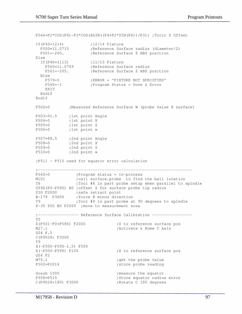
N700 Super Turn Series Manual Program Printouts
M17958 - Revision D 97
P566=P2*COS(P8)-P3*COS(ASIN((P4+P2*SIN(P8))/P3)) ;Toric Z Offset
If(P40=1214) ;12/14 Fixture P500=11.0715 ;Reference Surface radius (diameter/2) P501=-205. ;Reference Surface Z ABS position Else If(P40=1113) ;11/13 Fixture P500=11.0769 ;Reference Surface radius P501=-205. ;Reference Surface Z ABS position Else P579=5 ;ERROR = "FIXTURE NOT SPECIFIED" P560=-1 ;Program Status = Done & Error EXIT Endif Endif
P502=0 ;Measured Reference Surface W (probe value @ surface)
P503=91.5 ;1st point Angle P504=0 ;1st point X P505=0 ;1st point Z P506=0 ;1st point w
P507=88.5 ;2nd point Angle P508=0 ;2nd point X P509=0 ;2nd point Z P510=0 ;2nd point w
;P511 - P515 used for equator error calculation
;----------------------------------------------------------------- P560=0 ;Program status = in-process M101 ;call surface.probe to find the ball location T8 ;Tool #8 is part probe setup when parallel to spindle G59Z(P0-P590) B0 ;offset Z for surface probe tip radius Z30 F2000 ;safe retract point B-179 F3600 ;force B minus direction T9 ;Tool #9 is part probe at 90 degrees to spindle X-30 Z50 B0 F2000 ;move to measurement area
;----------------- Reference Surface Calibration ----------------- T0 Z(P501-P0+P586) F2000 ;Z to reference surface pos M27.1 ;Activate & Home C Axis G04 F.5 C(P9028) F3000 T9 X(-P500-P590-1.5) F500 X(-P500-P590) F100 ;X to reference surface pos G04 F2 M75.1 ;get the probe value P502=P2014 ;store probe reading
Gosub 1000 ;measure the equator P558=P515 ;Store equator radius error C(P9028+180) F3000 ;Rotate C 180 degrees
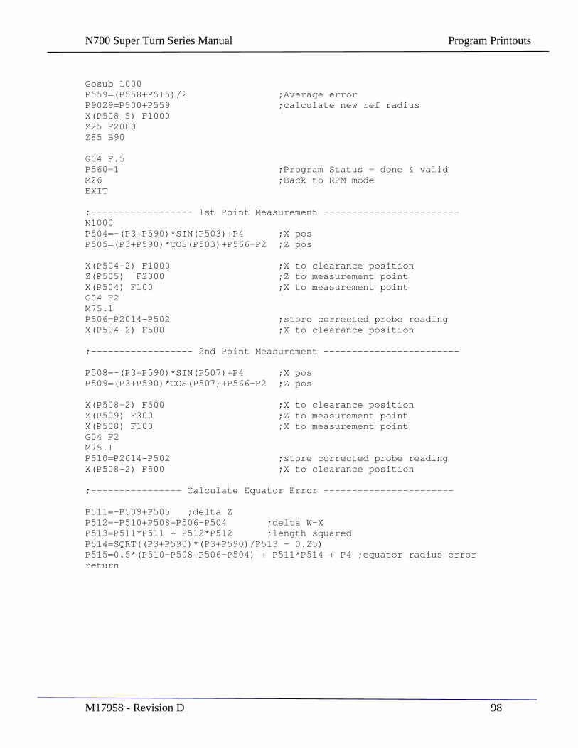
N700 Super Turn Series Manual Program Printouts
M17958 - Revision D 98
Gosub 1000 P559=(P558+P515)/2 ;Average error P9029=P500+P559 ;calculate new ref radius X(P508-5) F1000 Z25 F2000 Z85 B90
G04 F.5 P560=1 ;Program Status = done & valid M26 ;Back to RPM mode EXIT
;------------------ 1st Point Measurement ------------------------ N1000 P504=-(P3+P590)*SIN(P503)+P4 ;X pos P505=(P3+P590)*COS(P503)+P566-P2 ;Z pos
X(P504-2) F1000 ;X to clearance position Z(P505) F2000 ;Z to measurement point X(P504) F100 ;X to measurement point G04 F2 M75.1 P506=P2014-P502 ;store corrected probe reading X(P504-2) F500 ;X to clearance position
;------------------ 2nd Point Measurement ------------------------
P508=-(P3+P590)*SIN(P507)+P4 ;X pos P509=(P3+P590)*COS(P507)+P566-P2 ;Z pos
X(P508-2) F500 ;X to clearance position Z(P509) F300 ;Z to measurement point X(P508) F100 ;X to measurement point G04 F2 M75.1 P510=P2014-P502 ;store corrected probe reading X(P508-2) F500 ;X to clearance position
;---------------- Calculate Equator Error -----------------------
P511=-P509+P505 ;delta Z P512=-P510+P508+P506-P504 ;delta W-X P513=P511*P511 + P512*P512 ;length squared P514=SQRT((P3+P590)*(P3+P590)/P513 - 0.25) P515=0.5*(P510-P508+P506-P504) + P511*P514 + P4 ;equator radius error return
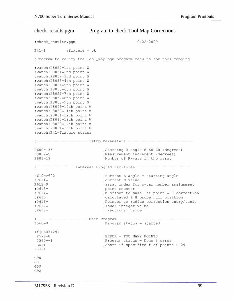
N700 Super Turn Series Manual Program Printouts
M17958 - Revision D 99
check_results.pgm Program to check Tool Map Corrections
;check_results.pgm 10/22/2009
P41=1 ;fixture = ok
;Program to verify the Tool_map.pgm progarm results for tool mapping
;watch:P8050=1st point W ;watch:P8051=2nd point W ;watch:P8052=3rd point W ;watch:P8053=4th point W ;watch:P8054=5th point W ;watch:P8055=6th point W ;watch:P8056=7th point W ;watch:P8057=8th point W ;watch:P8058=9th point W ;watch:P8059=10th point W ;watch:P8060=11th point W ;watch:P8061=12th point W ;watch:P8062=13th point W ;watch:P8063=14th point W ;watch:P8064=15th point W ;watch:P41=fixture status
;---------------------- Setup Parameters ----------------------------
P600=-35 ;Starting B angle @ X0 Z0 (degrees) P9032=5 ;Measurement increment (degrees) P603=19 ;Number of P-vars in the array
;---------------- Internal Program variables ------------------------
P610=P600 ;current B angle = starting angle ;P611= ;current W value P612=0 ;array index for p-var number assignment ;P613= ;point counter ;P614= ;W offset to make 1st point = 0 correction ;P615= ;calculated Z @ probe null position ;P616= ;Pointer to radius correction entry/table ;P617= ;lower integer value ;P618= ;fractional value
;---------------------- Main Program -------------------------------- P560=0 ;Program status = started
If(P603>29) P579=8 ;ERROR = TOO MANY POINTS P560=-1 ;Program status = Done & error EXIT ;Abort if specified # of points > 29 Endif
G90 G01 G59 G92
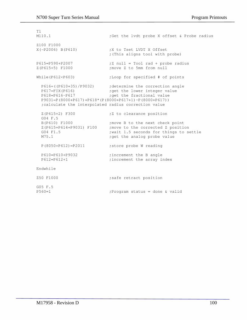
N700 Super Turn Series Manual Program Printouts
M17958 - Revision D 100
T1 M110.1 ;Get the lvdt probe X offset & Probe radius
Z100 F1000 X(-P2006) B(P610) ;X to Tset LVDT X Offset ;(This aligns tool with probe)
P615=P590+P2007 ;Z null = Tool rad + probe radius Z(P615+5) F1000 ;move Z to 5mm from null
While(P612<P603) ;Loop for specified # of points
P616=((P610+35)/P9032) ;determine the correction angle P617=FIX(P616) ;get the lower integer value P618=P616-P617 ;get the fractional value P9031=P(8000+P617)+P618*(P(8000+P617+1)-P(8000+P617)) ;calculate the interpolated radius correction value
Z(P615+2) F300 ;Z to clearance position G04 F.5 B(P610) F1000 ;move B to the next check point Z(P615+P614+P9031) F100 ;move to the corrected Z position G04 F1.5 ;wait 1.5 seconds for things to settle M75.1 ;get the analog probe value P(8050+P612)=P2011 ;store probe W reading P610=P610+P9032 ;increment the B angle P612=P612+1 ;increment the array index
Endwhile
Z50 F1000 ;safe retract position
G05 F.5 P560=1 ;Program status = done & valid

N700 Super Turn Series Manual Program Printouts
M17958 - Revision D 101
save_results.pgm Program to save data when prompted by operator
;save_results.pgm 10/22/09
P41=1 ;Fixure = ok
;watch:P41=fixture status
;This program saves the results from the Tool Mapping program ;(Tool_map.pgm) to persistent P-variables which are saved and ;restored through power OFF etc. The main program (P878.pgm) ;reads P9050 -> P9079 for the tool correction values.
P619=0 ;base index P620=29 ;number of entries
While(P619<P620) ;loop till all pvars are transfered P(9050+P619) = P(8000+P619) P619=P619+1 ;increment the index Endwhile
G04 F2 m2000.006
/upx.setup/autop_cfg.dat Configuration File for automated network communications (Bar Code Scanner file selection)
test test 0 mount_smb //DSSERVER:192.168.4.150/data /NETFILES part_data.p
N700 Super Turn Series Manual P Variable Assignments
M17958 - Revision D 102
SECTION 11
P Variable Assignments
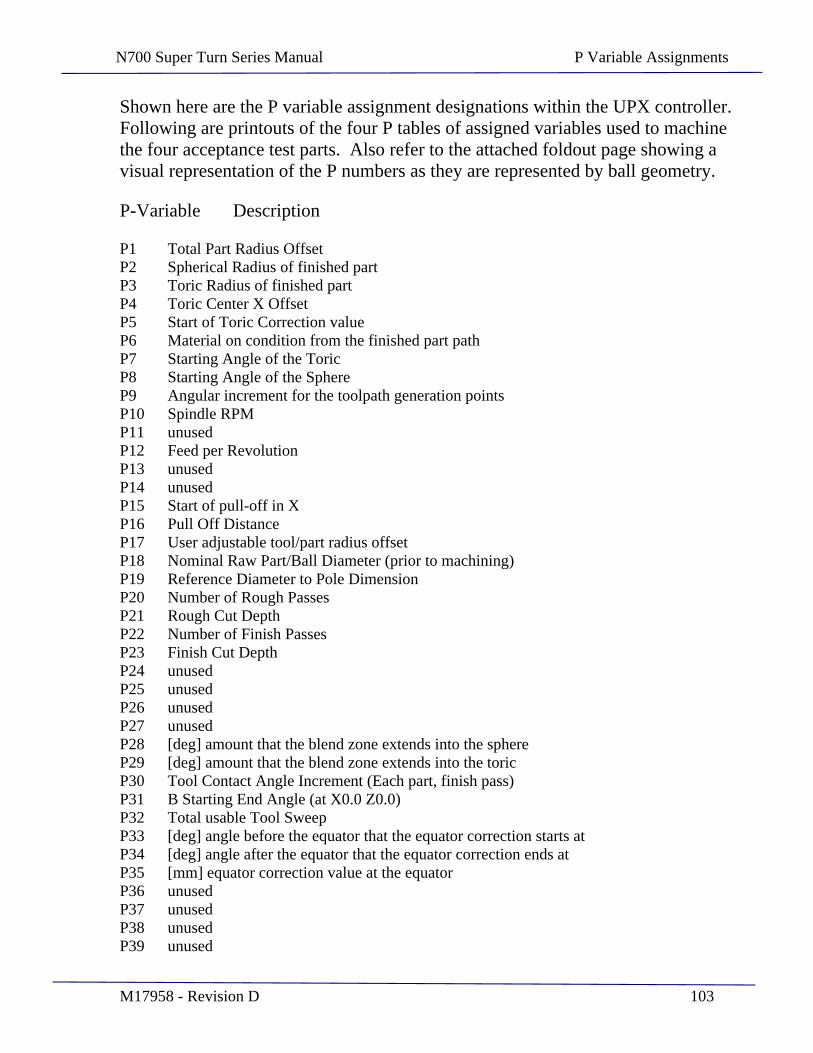
N700 Super Turn Series Manual P Variable Assignments
M17958 - Revision D 103
Shown here are the P variable assignment designations within the UPX controller. Following are printouts of the four P tables of assigned variables used to machine the four acceptance test parts. Also refer to the attached foldout page showing a visual representation of the P numbers as they are represented by ball geometry.
P-Variable Description
P1 Total Part Radius Offset P2 Spherical Radius of finished part P3 Toric Radius of finished part P4 Toric Center X Offset P5 Start of Toric Correction value P6 Material on condition from the finished part path P7 Starting Angle of the Toric P8 Starting Angle of the Sphere P9 Angular increment for the toolpath generation points P10 Spindle RPM P11 unused P12 Feed per Revolution P13 unused P14 unused P15 Start of pull-off in X P16 Pull Off Distance P17 User adjustable tool/part radius offset P18 Nominal Raw Part/Ball Diameter (prior to machining) P19 Reference Diameter to Pole Dimension P20 Number of Rough Passes P21 Rough Cut Depth P22 Number of Finish Passes P23 Finish Cut Depth P24 unused P25 unused P26 unused P27 unused P28 [deg] amount that the blend zone extends into the sphere P29 [deg] amount that the blend zone extends into the toric P30 Tool Contact Angle Increment (Each part, finish pass) P31 B Starting End Angle (at X0.0 Z0.0) P32 Total usable Tool Sweep P33 [deg] angle before the equator that the equator correction starts at P34 [deg] angle after the equator that the equator correction ends at P35 [mm] equator correction value at the equator P36 unused P37 unused P38 unused P39 unused
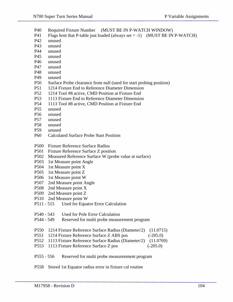
N700 Super Turn Series Manual P Variable Assignments
M17958 - Revision D 104
P40 Required Fixture Number (MUST BE IN P-WATCH WINDOW) P41 Flags host that P-table just loaded (always set = -1) (MUST BE IN P-WATCH) P42 unused P43 unused P44 unused P45 unused P46 unused P47 unused P48 unused P49 unused P50 Surface Probe clearance from null (used for start probing position) P51 1214 Fixture End to Reference Diameter Dimension P52 1214 Tool #8 active, CMD Position at Fixture End P53 1113 Fixture End to Reference Diameter Dimension P54 1113 Tool #8 active, CMD Position at Fixture End P55 unused P56 unused P57 unused P58 unused P59 unused P60 Calculated Surface Probe Start Position
P500 Fixture Reference Surface Radius P501 Fixture Reference Surface Z position P502 Measured Reference Surface W (probe value at surface) P503 1st Measure point Angle P504 1st Measure point X P505 1st Measure point Z P506 1st Measure point W P507 2nd Measure point Angle P508 2nd Measure point X P509 2nd Measure point Z P510 2nd Measure point W P511 - 515 Used for Equator Error Calculation
P540 - 543 Used for Pole Error Calculation P544 - 549 Reserved for multi probe measurement program
P550 1214 Fixture Reference Surface Radius (Diameter/2) (11.0715) P551 1214 Fixture Reference Surface Z ABS pos (-205.0) P552 1113 Fixture Reference Surface Radius (Diameter/2) (11.0769) P553 1113 Fixture Reference Surface Z pos (-205.0)
P555 - 556 Reserved for multi probe measurenment program
P558 Stored 1st Equator radius error in fixture cal routine
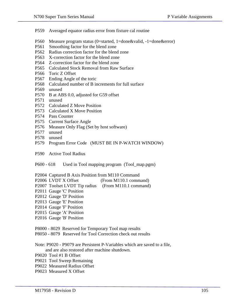
N700 Super Turn Series Manual P Variable Assignments
M17958 - Revision D 105
P559 Averaged equator radius error from fixture cal routine
P560 Measure program status (0=started, 1=done&valid, -1=done&error) P561 Smoothing factor for the blend zone P562 Radius correction factor for the blend zone P563 X-correction factor for the blend zone P564 Z-correction factor for the blend zone P565 Calculated Stock Removal from Raw Surface P566 Toric Z Offset P567 Ending Angle of the toric P568 Calculated number of B increments for full surface P569 unused P570 B at ABS 0.0, adjusted for G59 offset P571 unused P572 Calculated Z Move Position P573 Calculated X Move Position P574 Pass Counter P575 Current Surface Angle P576 Measure Only Flag (Set by host software) P577 unused P578 unused P579 Program Error Code (MUST BE IN P-WATCH WINDOW)
P590 Active Tool Radius
P600 - 618 Used in Tool mapping program (Tool_map.pgm)
P2004 Captured B Axis Position from M110 Command P2006 LVDT X Offset (From M110.1 command) P2007 Toolset LVDT Tip radius (From M110.1 command) P2011 Gauge 'C' Position P2012 Gauge 'D' Position P2013 Gauge 'E' Position P2014 Gauge 'F' Position P2015 Gauge 'A' Position P2016 Gauge 'B' Position
P8000 - 8029 Reserved for Temporary Tool map results P8050 - 8079 Reserved for Tool Correction check out results
Note: P9020 - P9079 are Persistent P-Variables which are saved to a file, and are also restored after machine shutdown. P9020 Tool #1 B Offset P9021 Tool Sweep Remaining P9022 Measured Radius Offset P9023 Measured X Offset

N700 Super Turn Series Manual P Variable Assignments
M17958 - Revision D 106
P9024 Part Measurement Counter P9025 Tool was just replaced indicator/flag P9026 Amount of Tool sweep currently used up P9027 Measure frequency P9028 C Reference Position (Position moved to after Homing) P9029 Current Reference Radius from Fixture Cal Routine P9030 User radius offset P9031 Tool Correction Radius offset from Tool Mapping P9032 Angle Increment Spacing of mapped tool
P9050 - 9079 Reserved for Tool Mapping
***** END OF P VARIABLE ASSIGNMENTS ******
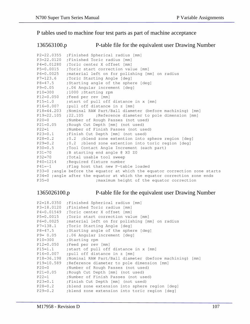
N700 Super Turn Series Manual P Variable Assignments
M17958 - Revision D 107
P tables used to machine four test parts as part of machine acceptance
136563100.p P-table file for the equivalent user Drawing Number
P2=22.0355 ;Finished Spherical radius [mm] P3=22.0120 ;Finished Toric radius [mm] P4=0.01280 ;Toric center X offset [mm] P5=0.0015 ;Toric start correction value [mm] P6=0.0025 ;material left on for polishing [mm] on radius P7=123.6 ;Toric Starting Angle [deg] P8=47.5 ;Starting angle of the sphere [deg] P9=0.05 ;.06 Angular increment [deg] P10=300 ;1000 ;Starting rpm P12=0.050 ;Feed per rev [mm] P15=1.0 ;start of pull off distance in x [mm] P16=0.007 ;pull off distance in z [mm] P18=44.203 ;Nominal RAW Part/Ball diameter (before machining) [mm] P19=22.105 ;22.105 ;Reference diameter to pole dimension [mm] P20=0 ;Number of Rough Passes (not used) P21=0.05 ;Rough Cut Depth [mm] (not used) P22=1 ;Number of Finish Passes (not used) P23=0.1 ;Finish Cut Depth [mm] (not used) P28=0.2 ;0.2 ;blend zone extention into sphere region [deg] P29=0.2 ;0.2 ;blend zone extention into toric region [deg] P30=0.5 ;Tool Contact Angle Increment (each part) P31=70 ;B starting end angle @ X0 Z0 P32=70 ;Total usable tool sweep P40=1214 ;Required fixture number P41=-1 ;Flag host that new P-table loaded P33=0 ;angle before the equator at which the equator correction zone starts P34=0 ;angle after the equator at which the equator correction zone ends P35=0 ;maximum height of the equator correction
1365026100.p P-table file for the equivalent user Drawing Number
P2=18.0350 ;Finished Spherical radius [mm] P3=18.0120 ;Finished Toric radius [mm] P4=0.01549 ;Toric center X offset [mm] P5=0.0015 ;Toric start correction value [mm] P6=0.0025 ;material left on for polishing [mm] on radius P7=138.1 ;Toric Starting Angle [deg] P8=47.5 ;Starting angle of the sphere [deg] P9= 0.05 ;.06 Angular increment [deg] P10=300 ;Starting rpm P12=0.050 ;Feed per rev [mm] P15=1.1 ;start of pull off distance in x [mm] P16=0.007 ;pull off distance in z [mm] P18=36.198 ;Nominal RAW Part/Ball diameter (before machining) [mm] P19=10.589 ;Reference diameter to pole dimension [mm] P20=0 ;Number of Rough Passes (not used) P21=0.05 ;Rough Cut Depth [mm] (not used) P22=1 ;Number of Finish Passes (not used) P23=0.1 ;Finish Cut Depth [mm] (not used) P28=0.2 ;blend zone extension into sphere region [deg] P29=0.2 ;blend zone extension into toric region [deg]
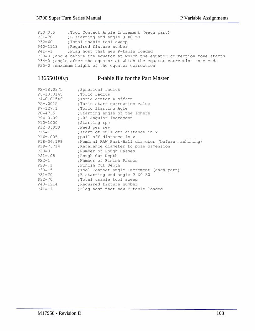
N700 Super Turn Series Manual P Variable Assignments
M17958 - Revision D 108
P30=0.5 ;Tool Contact Angle Increment (each part) P31=70 ;B starting end angle @ X0 Z0 P32=60 ;Total usable tool sweep P40=1113 ;Required fixture number P41=-1 ;Flag host that new P-table loaded P33=0 ;angle before the equator at which the equator correction zone starts P34=0 ;angle after the equator at which the equator correction zone ends P35=0 ;maximum height of the equator correction
136550100.p P-table file for the Part Master
P2=18.0375 ;Spherical radius P3=18.0145 ;Toric radius P4=0.01549 ;Toric center X offset P5=.0015 ;Toric start correction value P7=127.1 ;Toric Starting Agle P8=47.5 ;Starting angle of the sphere P9= 0.09 ;.06 Angular increment P10=1000 ;Starting rpm P12=0.050 ;Feed per rev P15=1 ;start of pull off distance in x P16=.005 ;pull off distance in z P18=36.198 ;Nominal RAW Part/Ball diameter (before machining) P19=7.714 ;Reference diameter to pole dimension P20=0 ;Number of Rough Passes P21=.05 ;Rough Cut Depth P22=1 ;Number of Finish Passes P23=.1 ;Finish Cut Depth P30=.5 ;Tool Contact Angle Increment (each part) P31=70 ;B starting end angle @ X0 Z0 P32=70 ;Total usable tool sweep P40=1214 ;Required fixture number P41=-1 ;Flag host that new P-table loaded
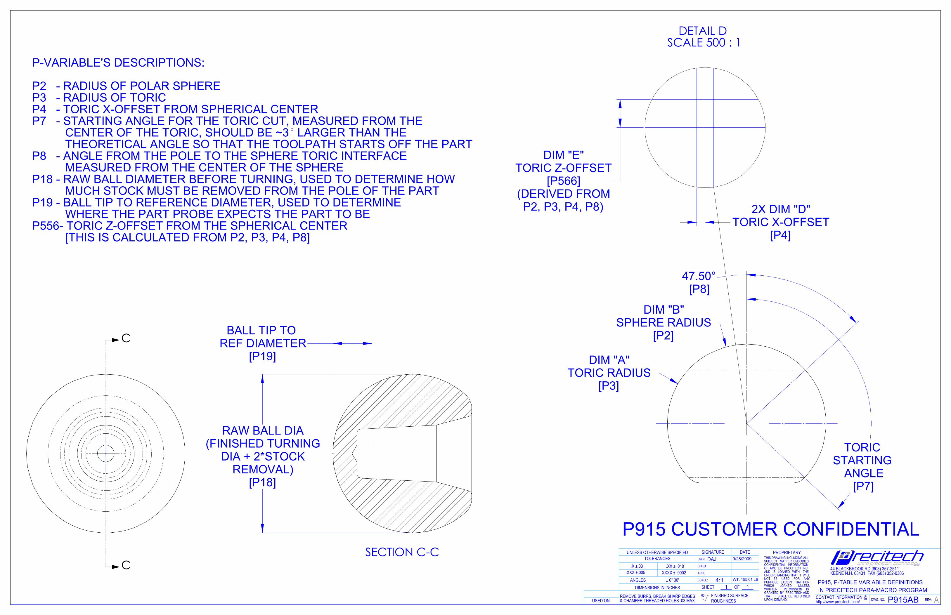
[P2]
DIM "B"SPHERE RADIUS
[P3]
DIM "A"TORIC RADIUS
[P7]
TORIC STARTING
ANGLE
47.50°[P8]
C
C
[P18]
RAW BALL DIA(FINISHED TURNING
DIA + 2*STOCK REMOVAL)
[P19]
BALL TIP TO REF DIAMETER
SECTION C-C
[P4]
2X DIM "D"TORIC X-OFFSET
P2, P3, P4, P8)
DIM "E"TORIC Z-OFFSET
[P566](DERIVED FROM
DETAIL D SCALE 500 : 1
P915 CUSTOMER CONFIDENTIAL
P-VARIABLE'S DESCRIPTIONS:
P2 - RADIUS OF POLAR SPHEREP3 - RADIUS OF TORICP4 - TORIC X-OFFSET FROM SPHERICAL CENTERP7 - STARTING ANGLE FOR THE TORIC CUT, MEASURED FROM THE
CENTER OF THE TORIC, SHOULD BE ~3 LARGER THAN THETHEORETICAL ANGLE SO THAT THE TOOLPATH STARTS OFF THE PART
P8 - ANGLE FROM THE POLE TO THE SPHERE TORIC INTERFACEMEASURED FROM THE CENTER OF THE SPHERE
P18 - RAW BALL DIAMETER BEFORE TURNING, USED TO DETERMINE HOWMUCH STOCK MUST BE REMOVED FROM THE POLE OF THE PART
P19 - BALL TIP TO REFERENCE DIAMETER, USED TO DETERMINEWHERE THE PART PROBE EXPECTS THE PART TO BE
P556- TORIC Z-OFFSET FROM THE SPHERICAL CENTER[THIS IS CALCULATED FROM P2, P3, P4, P8]
SHEET
TOLERANCES
CONTACT INFORMATION @http://www.precitech.com/
WT: 155.01 LB
SCALE:
ROUGHNESS REV:
11
UNLESS OTHERWISE SPECIFIED
FINISHED SURFACE
DWN
63DWG. NO.
OFP915, P-TABLE VARIABLE DEFINITIONS
.XXXX ± .0002± 0° 30'
A
SIGNATURE PROPRIETARY
USED ON
.X ±.03 .XX ± .010 44 BLACKBROOK RD (603) 357-2511KEENE N.H. 03431 FAX (603) 352-0306
P915AB
ANGLESDIMENSIONS IN INCHES
9/28/2009
CHKD
4:1.XXX ±.005
IN PRECITECH PARA-MACRO PROGRAM
DATE
APPD
DAJ THIS DRAWING INCLUDING ALLSUBJECT MATTER, EMBODIESCONFIDENTIAL INFORMATIONOF AMETEK PRECITECH INC.AND IS LOANED WITH THEUNDERSTANDING THAT IT WILLNOT BE USED FOR ANYPURPOSE EXCEPT THAT FORWHICH LOANED UNLESSWRITTEN PERMISSION ISGRANTED BY PRECITECH ANDTHAT IT SHALL BE RETURNEDUPON DEMAND.
REMOVE BURRS, BREAK SHARP EDGES & CHAMFER THREADED HOLES .03 MAX.
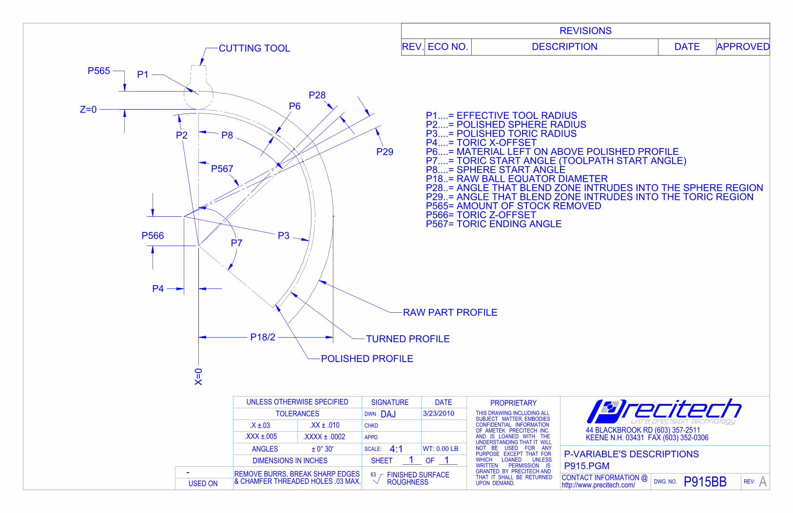
P2
P3
P6
P4
P566
P8
P7
P1P565
P18/2
P28
P567
P29
Z=0
X=0
POLISHED PROFILE
TURNED PROFILE
RAW PART PROFILE
CUTTING TOOL
-
P1....= EFFECTIVE TOOL RADIUSP2....= POLISHED SPHERE RADIUSP3....= POLISHED TORIC RADIUSP4....= TORIC X-OFFSETP6....= MATERIAL LEFT ON ABOVE POLISHED PROFILEP7....= TORIC START ANGLE (TOOLPATH START ANGLE)P8....= SPHERE START ANGLEP18..= RAW BALL EQUATOR DIAMETERP28..= ANGLE THAT BLEND ZONE INTRUDES INTO THE SPHERE REGIONP29..= ANGLE THAT BLEND ZONE INTRUDES INTO THE TORIC REGIONP565= AMOUNT OF STOCK REMOVEDP566= TORIC Z-OFFSETP567= TORIC ENDING ANGLE
REVISIONSREV. ECO NO. DESCRIPTION DATE APPROVED
WT: 0.00 LB
DAJ 3/23/2010
AP915BB
44 BLACKBROOK RD (603) 357-2511KEENE N.H. 03431 FAX (603) 352-0306
P-VARIABLE'S DESCRIPTIONSP915.PGM
CONTACT INFORMATION @http://www.precitech.com/USED ON
OF
DWG. NO. REV:
DIMENSIONS IN INCHES
THIS DRAWING INCLUDING ALLSUBJECT MATTER, EMBODIESCONFIDENTIAL INFORMATIONOF AMETEK PRECITECH INC.AND IS LOANED WITH THEUNDERSTANDING THAT IT WILLNOT BE USED FOR ANYPURPOSE EXCEPT THAT FORWHICH LOANED UNLESSWRITTEN PERMISSION ISGRANTED BY PRECITECH ANDTHAT IT SHALL BE RETURNEDUPON DEMAND.
PROPRIETARY
REMOVE BURRS, BREAK SHARP EDGES & CHAMFER THREADED HOLES .03 MAX.
FINISHED SURFACEROUGHNESS
± 0° 30'.XXXX ± .0002
.XX ± .010TOLERANCES
UNLESS OTHERWISE SPECIFIED
ANGLES.XXX ±.005
.X ±.03
63
APPD
CHKD
SHEETSCALE:
SIGNATUREDWN
DATE
1 14:1
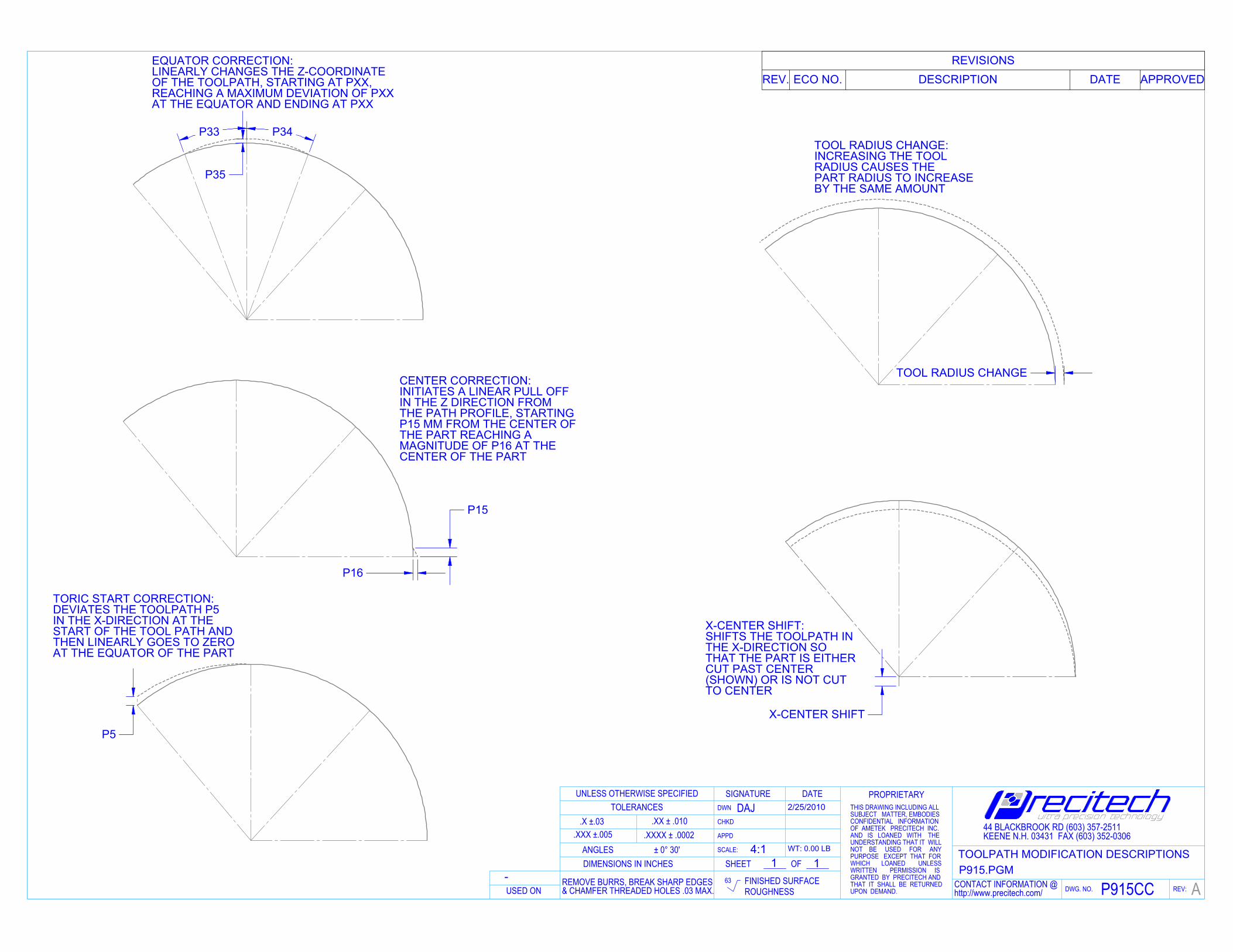
P5
TORIC START CORRECTION:DEVIATES THE TOOLPATH P5IN THE X-DIRECTION AT THESTART OF THE TOOL PATH ANDTHEN LINEARLY GOES TO ZEROAT THE EQUATOR OF THE PART
P35
P33 P34
EQUATOR CORRECTION:LINEARLY CHANGES THE Z-COORDINATE OF THE TOOLPATH, STARTING AT PXX,REACHING A MAXIMUM DEVIATION OF PXXAT THE EQUATOR AND ENDING AT PXX
P15
P16
CENTER CORRECTION:INITIATES A LINEAR PULL OFFIN THE Z DIRECTION FROMTHE PATH PROFILE, STARTINGP15 MM FROM THE CENTER OFTHE PART REACHING AMAGNITUDE OF P16 AT THECENTER OF THE PART
TOOL RADIUS CHANGE
TOOL RADIUS CHANGE:INCREASING THE TOOLRADIUS CAUSES THEPART RADIUS TO INCREASEBY THE SAME AMOUNT
X-CENTER SHIFT
X-CENTER SHIFT:SHIFTS THE TOOLPATH INTHE X-DIRECTION SOTHAT THE PART IS EITHERCUT PAST CENTER(SHOWN) OR IS NOT CUTTO CENTER
-
REVISIONSREV. ECO NO. DESCRIPTION DATE APPROVED
DATEDWN
SIGNATURE
SCALE:
SHEET
CHKD
APPD
63
.X ±.03.XXX ±.005
ANGLES
UNLESS OTHERWISE SPECIFIEDTOLERANCES
.XX ± .010.XXXX ± .0002
± 0° 30'
ROUGHNESSFINISHED SURFACE
PROPRIETARY
DIMENSIONS IN INCHES
REV:DWG. NO.
OF
USED ONCONTACT INFORMATION @http://www.precitech.com/
P915.PGMTOOLPATH MODIFICATION DESCRIPTIONS
44 BLACKBROOK RD (603) 357-2511KEENE N.H. 03431 FAX (603) 352-0306
P915CC A
2/25/2010DAJ
WT: 0.00 LB
4:11 1
THIS DRAWING INCLUDING ALLSUBJECT MATTER, EMBODIESCONFIDENTIAL INFORMATIONOF AMETEK PRECITECH INC.AND IS LOANED WITH THEUNDERSTANDING THAT IT WILLNOT BE USED FOR ANYPURPOSE EXCEPT THAT FORWHICH LOANED UNLESSWRITTEN PERMISSION ISGRANTED BY PRECITECH ANDTHAT IT SHALL BE RETURNEDUPON DEMAND.
REMOVE BURRS, BREAK SHARP EDGES & CHAMFER THREADED HOLES .03 MAX.