american society of civil engineers archives... · american society of civil engineers ......
TRANSCRIPT


May, 1930.]
AMERICAN SOCIETY OF CIVIL ENGINEERS INSTITUTED 1852
PAPERS AND DISCUSSIONS Tbis Society is not responsible for any statement made or opίnion expresβed
in its publications.
ANALYSIS OF CONTINUOUS FRAMES ΒΥ DISTRIBUTING FIXED-END MOMENTS
ΒΥ HARDY 0Ross,* Μ. ΑΜ. Soc. Ο. Ε.
SYNOPSIS
919
The purpose of this paper is to e:xplain a method which has ./ been found useful in analyzing frames which are statistiM.ll indeterminate. The essential idea which the writer wi8hes to present involves no mathematical relation8 except the 8implest arithmetic. It is true that in order to apply the method it is neces8ary to determine certain constants mathematically, but the 1nean8 to be used in determining these con8tant8 are not di8cussed in the paper, nor a1·e they a part of the method. These constants have been derived by 80 many writer8 and in 80 many slightly di:fferent ways that there is little occasion to repeat here the whole procedure.
The reaction8 in beam8, bents, and arche8 which are immovably fixed at their ends have been extensively di8cussed. They can be found comparatively readily by methods which are more or less 8tandard. The method of analysis herein presented enables one to derive from these the moments, shears, and thru8t8 required in the design of complicated continuous frames.
DEFINITIONS
For convenience of reference, de:finitions of three terms will ,be introduced at once. These terms are ":fixed-end mψnent", "sti:ffness", and "carry-over factor".
By ":fixed-end moment" in a member is meant the moment which would exist at the ends of the member if its ends were :fixed against rotation.
"Sti:ffness", as herein used, is the moment at one end of a member (which is on unyielding supports at both ends) necessary to produce unit rotation of that end when the other end is :fixed. Π one end of a member which is on unyielding supports at both ends is
rotated while the other end is held fixed the ratio of the moment at the :fixed NoτE.-Written dίscussion on this paper will bc closed in September, 1930, Proceedin-gs. • Prof. , Structura1 Eng., Univ. of Illinols, Urbana, Ill.
Γ
920 .ΛN.ALYSIS OF CONTINUOUS FR.AMES [Papers.
end to the moment producing rotation at the rotating end is herein called the "carry-over factor."
EFFECT OF J ΟΙΝΤ RoTATION
Imagine any joint in a structure, the members of which a1·e being deformed by loads, or in some other way, to be first held against rotation and then released. Call the algebraic sum of the fixed-end moments at the joint the "unbalanced fixed-end moment". Before the joint is release.d this unbalanced fixed-end moment will not usually be zero; after the joint is released, the sum of the end moments at the joint must be zero. The total change in end moments, then, must equal the unbalanced fixed-end moment. This may be stated in another way by saying that the unbalanced fixed-end moment has been "distributed to" the connecting members in some ratio.
When the joint is released all connecting members rotate through the same angle and this rotation at the end is accompanied by a change in end moment. The change in end moments is proportional to the "sti:ffness" of the members.
Hence, it may be said that when the joint is released the unbalanced fixed-end moment is distributed among the connecting members in proportion to their sti:ffness.
The rotation of the joint to produce equilibrium induces moments at the other ends of the connecting members. These are equal in each member to the moments distributed at the rotating joint multiplied by the carry-over factor at the ~otating end of the member. This follows from the definition of "carry-over factor".
ΜοΜΕΝΤ DISTRIBUTION
The method of moment distribution is this: (α) Imagine all joints in the structure held so that they cannot rotate. Compute the moments at the ends of the members for this condition; (b) at each joint distribute the unbalanced fixed-end moment among the connecting members in proportion to the constant for each member defined as "sti:ffness"; (c) multiply the moment distributed to each member at a joint by the carry-over factor at that end of the member and set this product at the other end of the member; (d) distribute these moments just "carried over"; (e) repeat the process until the moments to be carried over are small enough to be neglected; and (f) add all moments -fixed-end moments, distributed moments, moments carried over-at each end of each member to obtain the true moment at the end.
Το the mathematically inclined the method will appear as one of solving a series of normal simultaneous equations by successive approximation. From an engineering viewpoint it seems simpler and more useful to think of the solution as if it were a physical occurrence. The beams are loaded or otherwise distorted while the joints are held against rotation; one joint is then allowed to rotate with accompanying distribution of the unbalanced moment at that joint and the resulting moments are carried over to the adjacent joints; then another joint is allowed to rotate while the others are held against rotation; and the process is repeated until all the joints are "eased down" into equilibrium. ·

May, 1930.] ANALYSIS OF CONTINUOUS FRAMES 921
ΒΕΑΜ ΟοΝsτΑΝτs
This method of analysis is dependent on the solution o:f three problems in the mechanics o:f materials. These are the determination o:f the :fixed-end moments, o:f the sti:ffness at each end, and of the carry-over :factor at each end for each member of the frame under consider~tion. The determination of these values is not a part of the method of moment distribution and is not discussed in this paper.
The sti:ffness of a beam of constant section is proportional to the moment of inertia divided by the span length, and the carry-over factor is - i.
The proof or derivation of these two statements and the derivation of formulas for :fixed-end moments is left to the reader. They can be deduced by the use of the calculus; by the theorems of area-moments; from relations stated in Bulletin 108 of the Engineering Experiment Stationofthe University of Illinois (the Slope-De:flection Bulletin); from thetheoremofthreemoments; by what is known to some as the column analogy method ;* or by any of the other corollaries o:f geometry as applied to a bent member. Formulas for :fixed-end moments in beams of uniform section may be found in any structural handbook.
SroNs oF ΤΗΕ BENDING ΜοΜΕΝτs
It has seemed to the writer very important to maintain the usual and familiar conventions for signs of bending moments, since these are the conventions used in design.
For girders the usual convention is used, positive moment being such as sags the beam. For vertical members the same convention is applicable as for girders if the sheet is turned to read from the right as vertical members on a drawing are usually read. The usual conventions for bending moments are, then, applicable to both girders and columns if they are looked at as a drawing is usually lettered and read.
Moments at the top o:f a column, as the column stands in the structure, should be written above the column and those at the bottom of the column, as the column stands in the structure, should be written below the column when the sheet is in position to read the columns. This is necessary because positive moment at the right end of a beam and at the top of a column both represent tendencies to rΌtate the connected joint in the clockwise direction.
It makes no di:fference whether girder moments are written above or below the girder. Either arrangement may be convenient. Oonfusion will be avoided by writing column moments parallel to the column and girder moments parallel to the girders.
When any joint is balanced the total moment to the right and to the left of the support is the same, both in absolute value and in sign. The unbalanced moment is the algebraic di:fference of the moments on the two sides of the joint.
LIMITATION OF METHOD
From the fact that the terms, "sti:ffness?' and "ca:ι;ry-over factor", have been defined for beams resting on unyielding supports, ' it follows that direct
• "The Column Analogy," by Hardy Cross, Μ. Α . Soc. Exper im ent Statίon, Unίv . of Πlinois, Urbana, Ill. ('In press.
)( 2 /.J

922 ΑΝ ALYSIS OF CONTINUOUS FRAMES [Papers.
application of the method is restricted to those cases where the joint do not move dur'ng the process of moment distribution. , The method, however, can be applied in an indirect way to ,cases in which the joints are displaced during the moment distribution, as indicated later.
As the method has been stated, it is restι·icted only by this condition that the joints are not displaced. If this condition is satisfied it makea no difference whether the members are of constant or of varying section, curved or straight, provided the constants, (α) fixed-end moments at each end, (b) stiffness at each. end, and (c) carry-over factor at each end, are known or can be determined. Such values can be derived by standard methods and may be tabulated for different types of members and conditions of loading.
It will be found that i.n most cases accuracy is needed only in the fixed-end moments. It does not ordinarily make very much difference how, within reason, the unba]anced moments are distributed, nor, within reason, how much of the distributed moments are carried over.
In the illustration which follows it has been assumed that the members are straight and of uniform section. The stiffnesses, then, are proportional to the moments o:f inertia, (Ι), divided by the lengths, (L), but the rel~tive values
Ι given for L in this problem might quite as well be the relative stiffness of a
series o:f beams o:f varying section. In this latter case, however, the carry-over factors for the beams would not be- i.
Β
,..: Oocioόo...;o....;oMo -100.00 ::1[8 ~ ~ ~ ~ ~
7ιιιιι7 ~~:gb + 3.33 - 5.34 + 3.56 - 0.55 + 0.37
® ~ g:~~ - 0.10 .::J1:QZ -37.12
Α
FIG. 1.
lLL USTRA ΤΙΟΝ
-100.' ο +62.50
1
-37.50 + 6.25 + 5.50 - 0.78 1 ... 0.47 + 6.68 ... 9.38 .. 1.69 - 1.01 ... 0.69 1 - 0.12 - 0.51 + 030 • 0.48 .. 0.25 - 0.15 1 ... 0.08 + 0.13 - 0.08 - 0.13 + 0.08 --::ms-
1
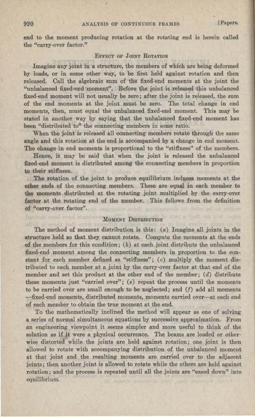
The illustration given (Fig. 1) is entirely academic. It is not intended to represent any particular type of structure nor any, probable condition o:f loading. It has the advantage :for the purpose o:f this paper that it involves all the conditions that can occur in a frame which is made up o:f straight members and in which the joints are not displaced.
1

May, 1930.] .ΛN.ALYSIS OF CONTINUOUS FR.AMES 923
The loads on the :frame are supposed to be as indicated. The relative Ι
νa1ues of L for the different members are indicated in circles.
The fixed-e~d moments in all members aι·e fiτst written. In this problem they are arbitrarily assumed to be as shown, as follows: at Λ, Ο; at Β, in Β Λ, Ο, and in Β .Ο,- 100; at Ο, in Ο Β,- 100, in Ο lι\ +· 80, in Ο D,- 200, and in Ο G, -50; at F, + 60; at G,- 50; at D, in D Ο, - 100, and in D Ε, Ο; at Ε, in Ε D, Ο, and in the cantilever, - 10.
Be:fore proceeding to a solution o:f the problem, attention may be called to the arraηgement o:f the computations. The moments in the girders are wι·itten parallel to the girder·s; those in the columns, parallel to~ the columns. The original fixed-end moments are written next to the members in which they occur, the successive moments distributed or carried over being· written above or below these, but farther :from the member.
The arrangement of the moments in the columns in positions above the columns, when the paper is turned into a position to write these moments, :for the top of the columns (at Β, F, and 0), and in positions below the columns for the bottom of the columns (at Λ, Ο, and G), is an essential part of the sign convention adopted.
The rnoment at Ο in the girder, Β Ο, is written above the giι·der in order to get it out of the way. Otherwise, it · makes no difference whether the moments are written above or below the girder.
The signs of the :f:ixed-end moments are determined by observing the direction of .flexure at the ends of the members due to the loads. In order to apply to the columns the ordinaιΎ conventions for signs of bending moments it is necessary to turn the drawing of the structure.
The reader should realize that the solution is built up step by step. It is always the last :figures showing that are to be operated on-distributed or carried ove:r-so that in ordinary framework there is little chance for confusion as to what step should be taken next.
Distribute at each joint the unbalanced moment, as follows:
· 1.-At Λ there is no moment. 2.-At Β there is an unbalanced moment of -100 on one side of the joint.
This moment is distributed to Β Λ and to Β Ο in the ratio, 2 : 4, so that the 2 4
distributed moment to Β Α is -2-- 100 = 33.33 and to Β 0,--100 = 66.67. +4 2+4
The signs are written in the only way possible to balance the joint by giving the same total moment (- 33.33) both to left and right of the joint.
3.-At Ο, the unbalanced moments are, in Ο Β, -100, and in Ο G,- 50, giving a total of -150 on the left of the joint; in Ο F, + 80, and in Ο D, -200, giving a total of -120 on the right of the joint. The total unbalanced moment at the joint, which is the difference between the total moment on the left and on the right of the joint, is 30. This is now distributed in the respective propor~ions, as fol1ows:
/ 924 ANALYSIS OF CONτiNUOUS FRAMES [Papcrs.
Το ΟΒ,
4 30 = 10
4+2+5+1 to OF,
2
4+2+5+1 30 = 5
to OD, 5
2 30 = 12.5 4+ +5+1
and, to Ο G, 1
4 + 2 + 5 + 1 30 = 2.5
The1·e is only one way to place the signs o:f the distributed moment~ so that the total is the same on both sid€s o:f the joint. This is done by reducing the excess negative moment on the le:ft and increasing the negative moment on the right.
4.-At F, the unbalanced moment is + 60. The hinge has no sti:ffness. The moment, then, is distributed between the member, F .0, and the hinge in the ratio, 2 : Ο; all o:f it goes to the member. The total balanced moment is +· 60- 60 =Ο, as it must be at a :free end.
5.-At G, the abutment is infinitely sti:ff and the unbalanced moment, - 50, is distributed between the member, G Ο, and the abutment in the ratio, 1 : οο. The member gets none of it; the end stays fixed.
6.-At D, the unbalanced moment, -100, is distributed to D Ο and to D Ε in the ratio o:f 5 : 3.
7.-At Ε, the unbalanced moment is -10 in the cantilever. Since the cantilever has no sti:ffness, this unbalanced moment is distributed between the beam, Ε D, and the cantilever in the ratio, 3 : Ο. This means that all o:f it goes to Ε D.
All joints have now been balanced. Ν ext, carry over :from each end o:f each member one-hal:f the distributed moment just written, reverse the sign, and write it at the other end o:f the member. Thus, carry over, successively, in Λ Β, Ο from Λ to Β and +· 16.67 :from Β to Λ; in Β Ο,- 33.34 :from Β to . Ο and -5.0 :from Ο to Β; in Ο F, +· 2.5 :from σ to F and + 30 :from F to .0; in Ο G, Ο :from G to Ο and -1.25 from σ to G; in Ο D, + 6.25 from Ο to D and - 31.25 from D to Ο; and in D Ε, + 18.75 :from D to Ε and + 5.00 :from Ε to D.
Distribute the moments just caπied over exactly as the original fixed-end moments were distributed. Thus, at Λ, + 16.67 is distributed Ο to Λ Β (fixedended) ; at Β, - 5.0 is distributed as - 1.67 and + 3.32; at Ο, the unbalanced moment is (- 33.34 +· Ο) - C+ 30.00 - 31.25) = - 32.09 which is distributed as + 2.67, + 10.68, - 5.34, and - 13.35; at F, + 2.50 is distributed as - 2.5 to the member; G is fixed-ended; at D, + 1.25 is distributed as- 0.78 and + 0.47; at Ε, the unbalanced + 18.75 is distributed to the member as -18.75.
The moments distributed are now carried over as be:fore and then re-distributed; and the process is repeated as often as desired. The procedure should

:May, 1930.] ΔΝ ΔLYSIS OF CONTINUOUS FRΔ:M:ES 925
be stopped after each distribution, however, and a check made to see that statics (.Σ Μ = Ο) is satisfied.
When it is felt that the process has gone far enough, all moments at each end of each member are added to give the total moment at the joint. After the moments at the joints have be~n determined, all other quantities, such as moments and shears, may be obtained by applying the laws of statics.
CoNVERGENOE OF REsuLτs
The distribution herein has been carried out with more precision than is ordinarily necessary, in order to show the convergence of the results. Το show the rate of conveι·gence, the successive values of the moments at the joints after successive distributions are given in Table 1.
TABLE 1.-CONVERGENOE OF RESULTS.
Successive vιιlues After one After two After thre.e After four After tlve After six of bending distribution di!itri bu tions distributions distri butionR distributions distributions
(two rows (four rows (sίχ rows (eig-ht rows (ten rows (twelve rows moment at joint. of tlgures). of tlgures). of tlgures) . of tlguι·es). of tlgures). of tlgures).
.Α ....... . ο + 16.67 + 17.50 + 18 .39 + 18.48 + 18.!i5 Β
ϊ~'ά'ji - 83.84 -85.01 - 36.79 - 36.97 - 37.10 - 87.18
f -90.00 - 112.66 -113.22 -114 .24 -114.23 -114.26 c
ι "CF + 75.00 + 99.66 +100.36 +101.82 +101 .36 +101.41 "CD -212 .50 - 257.10 -258 .09 -259.89 -259.88 -259.93 '' C G -47.50 - 44.83 - 44.55 - 44.36 - 44.31 - 44.28
D ...... .. - 37.50 - 82 .03 -23.66 - 23.48 - 23.15 - 23.15 Ε ······· · - 10.00 - 10.00 -10.00 - 10.00 - 10.00 - 10.00 F ....... . ο ο ο ο ο ο G ........ - 50.00 - 51.25 - 52.59 - 52.73 -52.88 -52.86
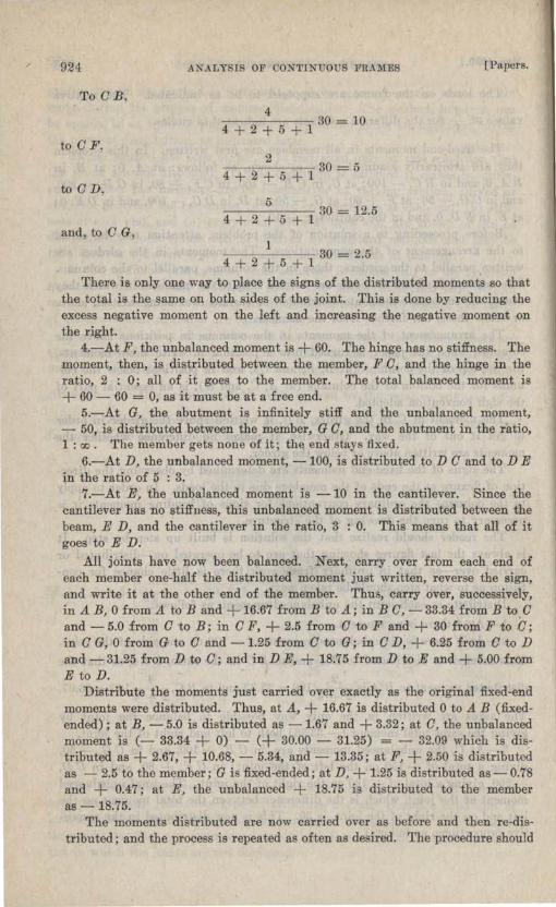
For most purposes the computations might as well have been stopped after the seoond distribution. Had this been done, the solution would have appeared as shown in Fig. 2.
For any practical purpose the computation might in this case have been stopped after the third distribution. In general, two or three distributions are sufficient. This is not true in all instances, but in any case the exactness of the solution at any stage will be indicated by the magnitude of the moments carried over in the members.
V ARIATIONS OF ΤΗΕ METHOD
The writer has developed and used at di:fferent times several variations of the method shown, but the original method is itself so simple and so easy to remember that he finds himself inclined to discard the variants.
One variant is perhaps worth reco:iding. It is rather tedious to carry moments out to the end o:f a member which is :free to rotate and then balance the moment and carry it back again. This may be avoided by releasing the free end once for all and leaving it :free. In this case, :for beams of constant section, the sti:ffness of the beam is to be taken three-fourths as great* as
* The moment n eeded to produce a given rotation at one end of a beam when the other end is free is three-fourths as great as if the other end is tlxed .

926 ANALYSIS OF CONTINUOUS FRAMES [Papeι·s.
Ι the relative --value would indicate. Afteι· tlιe end of tlιe beanι is once
L released, no moments are carried over to it.
OoaaEoτiNG FOR SmE-SWAY
Single square or trapezoidal frames, portals, L-frames, box culverts, and similar structures act as simple continuous beams if theι·e is no transverse defl.ection. Ιί they are symmetrical as to form and loading, they will not defl.ect sidewise and if they are restrained against sidewise movement, they cannot so defl.ect.
Β 0, ..... "" ~ ,...;ο~ο -100.0 ι ι ι + 66.7
®
- 5.0 + 3.j -35.0
"1"" οοlό Ιό ........ + + ~
Α
®
-112.6 + 10.7 C!C!C!"11": - 33.3 ~"'~"' ~ + 10.0 + ι+ ι + -100.0 c
:;: <"Jo<-Jg -200.0 "'I" "'0 ι + + ι - 12.5
- 31.3 - 13.4 -257.2
FIG. 2.
Side-sway of frames due to dissymmetry of the frame is raι·ely an important ίactor in design. Ooτrection :for side-sway may be made by a method which may be applied also in cases of transverse loading on bents. The method is to consider that the bent does not sway sidewise and analyze it as a series of continuous beams. The total shear in the legs will not now, except by accident, equal the shear which is known to exist. The difference must be a force which prevents side-sway.
Now, assume all joints held against rotation, but the top of theΘ moved sidewise. Assume any series οί fixed-end moments in the legs such that alllegs hav~ the same defl.ection. In this case for members of uniform section fixed-end
. Ι nιoments 1n columns vary as L2 • Distl'ibute these fixed-end ωoωents and find
the total shear in the legs. The changes in moments due to side-sway will then be to the moments just computed in the same algebraic ratio as the total unbalanced horizontal shear in the legs due to side-sway, \\·hen the frame is analyzed as a continuous girder, is to the shear just computed.

~\1ay, 1930.1 ANΔLYSIS OF CONTINUOUS FRΔME 927
MuLη-SτoRIED BENTS
Bents οί rnoι·e than one story, subject to side-sway, either as a result οί unbalanced loading or due to horizontal forces, may be solved by this method. It is understood that exact solution of uch pι·oblems is not commonly of great interest. It is the approximate e:ffect that is desired rather than exact analysis.
Το analyze by this method a two-story bent it will be necessary to make two configurations-one for each story. From the assumed shear in each story (producing, of cour e, shears in the other stories), a set of moment values may be obtained. These may be combined to obtain the true sheaι·s, and fι·om the true shears the trυe mornent ίol1ow.
GENERAL APPLICAτiON OF ΤΗΕ ΜΕΊ'ΗΟ])
The method herein indicated of distributing unbalanced moments may be extended to include unbalaJιced joίnt foι·ce . As thus extended it has very wide application. Horizontal or vertical rea.ctions may be distributed and carried over and thus a quick estimate made of the e:ffect of many complicating elements in design. The writer has used it in studying such problems as continuous arch series, the e:ffect of the de:flection of suppω·tίng girders, and other phenomena.
An obvious application of moment distribution occurs in the computation of secondaι·y stresses in trusses. Many other applications wi]] doubtless suggest themselves, but it has been thought best to restrict this paper chie:fly to continuous frarnes in wh:ich the joints do not rnove.
00NCLUSION
The paper has been confined to a method of analysis, because it has seemed wiser to so restrίct it. It is not then an oversig·ht that it does not deal with: (1) Methods of constructing curves of maximum moments; (2) methods of con~tructing curves of maximurn shears; ( 3) the importance of analyses for continuity in the design of concι·ete girders; ( 4) :flexural stresses in concrete columns; (5) methods of constructing in:fluence lίnes; (6) the degτee to which continuity exists in ordinary steel frames; (7) continuity in welded steel fι·ames; (8) plastic deformation beyond the yield point as an element in interpι·eting secondary stress computations; (9) the e:ffect of time yie]d on moments and shears in continuous concι·ete frames; (10) plastic flow of concrete as a factor in the design of continuous concrete frames; (11) whether in concrete frames it is better to g·uess at the moments, to take results from studies made by Winkler fifty years ago, or to compute them; (12) the e:ffect of torsion of connecting members; (13) the relative economy of continuous structures; (14) the relative :flexibility of conti~uous structures; (15) the application of methods of continuous frame analysis to the design of :flat s]abs; (16) probaability of loading and reveι·sal of stress as factors in the design of continuous ίι·ames; (17) the relation of precision in the determinat:ion of shears and / moments to precision in the determination of fiber stresse , and a dozen other considerations bearing on the design of continuous frames.
The writer has discussed several of these questions e1sewhere. He hopes that readers will discuss some of them now.

928 ANALYSIS OF CONTINUOUS FRA::M:ES [Papers.
Α method of analysis has value if it is ultimately useful to the designer; not otherwise. There are apparently three schools of thought as to the value of analyses of continuous frames. Some say, "Since these problems cannot be solved with exactness because of physical unceι·tainties, why try to solve them at all ~" Others say, "The values of the moments and shears cannot be found exactly ; do not try to find them exactly ; use a metl1od of analysis which will combine reasonable precision with speed." Still όthers say, ''It is best to be absolutely exact in the analysis and to introduce all elements of judgment after making the analysis.''
The wl'iter belongs to the second school; he respects but finds di:fficulty in understanding the viewpoint of the other two. Those who agree with his viewpoint will find the method herein explained a useful guide to judgment in design.
Members of the last named school of thought should note that the method here presented is absolutely exact if absolute exactness is desired. It is a method of successjve approxirnations; not an appr.oxirnate rnethod.
/