american-eurasian journal of sustainable … 4 icmmmm 2014/12-25.pdf13 suhaidah hussain et al, 2014...
TRANSCRIPT

Copyright © 2014, American-Eurasian Network for Scientific Information publisher
American-Eurasian Journal of Sustainable Agriculture ISSN: 1995-0748
JOURNAL home page: http://www.aensiweb.com/AEJSA 2014 Special; 8(11): pages 12-25.
Published Online. 25 October 2014 Research Article
Corresponding Author: Suhaidah Hussain, Faculty of Business & Management, International College of Automotive,
Pekan, Pahang, Malaysia.
Tel : +609-4242406, Fax : +609-4242500; E-mail: [email protected].
Reduction of Purging Material In Injection Moulding: Problem Based Learning (Pbl) Experience 1H. Suhaidah, 2W.S. Wan Ahmad Najmuddin, 3S. Safiza, 4Y. Muhammad Firdaus, 5A. Alif Amirul and 6M.N. Khairul Aswad 1Faculty of Business and Management/Faculty of Engineering & Technology, International College of Automotive, Pekan, Pahang, Malaysia Received: 15 September 2014; Accepted: 5 October 2014; Available online: 25 October 2014
© 2014 AENSI PUBLISHER All rights reserved
ABSTRACT
In a manufacturing company, lack of knowledge towards certain process lead to the uncontrolled waste most of the time. Problem Based Learning (PBL) promotes the successful and innovative method for engineering education. This is a project by final year students
of International College of Automotive (ICAM) which aim to solve the problem of one of the subsidiary company of DRB-HICOM that
involved in the injection moulding process. This project is aimed to solve the problem in reducing the wastages of purging in injection moulding. This study is prepared based on the series of experiment conducted to determine the issue of exceeding material usage. By using
the Maastricht Methods (1976), the `Seven Step' was developed to help the students to analyse the problem; (i) clarify the concepts; (ii)
define the problem; (iii) analyse the problem; (iv) find the explanation; (v) formulate the learning objective; (vi) search for further information; and (vii) report and test new information. The modification of the hopper in the injection moulding machine find the good
solution for minimizing the wastages of purging process. The data collected before and after the implementation of this project prove the
success of this project. Albeit, the methodology had produced an essential results in the case when raw material become a waste issue but, in general, the method could be more extended on details approach. Therefore, the future work on appropriate lean manufacturing concept
should be considered for the application of determining the issue of excessive material usage.
Key words : Problem Based Learning (PBL); Lean Manufacturing; Injection Moulding Waste
INTRODUCTION
The curriculums of all diploma and degree
programmes in ICAM are tailored to the current
needs of the industry. The inputs from industries are
gathered via the Subject Matter Experts (SME) which
are appointed based on their experiences and
credentials in particular industries or areas. Hence,
during teaching and learning activities, students are
exposed to the real industry scenarios. Throughout
their studies, students are attended to PBL methods. It
is expected that the students can engage their
theoretical knowledge in solving issues or problems.
It is proven that the application of PBL in teaching
and learning gave the advantages to the students
during their internship programme in solving the
company issues or problems.
One of the significant outcomes that had proven
to be beneficial to the company is where the
improvement of injection moulding process in which
it had reduced the operation cost.
The injection moulding machine is one of the
significant and rational forming methods existing for
processing plastic material. A major part in this
development has been implemented by the forward
thinking machinery industry, which has been quick to
seize on innovation and incorporate them into plastic
moulded products. A major focus continues to be on
finding more rational means processing the and less
new plastics of processing the and less new plastics
that are develop and also produce more cost-efficient
products [17].
In the operation of injection moulding cycle,
plastic granules are fed to the machine through the

13 Suhaidah Hussain et al, 2014 / American-Eurasian Journal of Sustainable Agriculture 8(11), Special, Pages: 12-25
hopper. Upon entering into the barrel, the screw
rotate and moves the granules forward in the screw
channel. The granules are forced against the wall of
the barrel, and melt due to bolt friction heat generated
by the rotating screw and the conduction from the
heating units along the barrel. The molten material is
conveyed to the tip of the screw. During this time,
pressure developed against the „closed off‟ nozzle and
the screw moves backward to accumulate a reservoir
of melt at the front end of the screw barrel.
Purging is the balance of material found inside
the barrel. The purging process consists of three (3)
phases; i.e. purging 1: to take out extra material inside
the barrel; purging 2: to clean up leftover material
inside the barrel (flushing the barrel) and colour
change: fill up with new material and purge out to
finish flushing process (in order to get good material
colour). The aim of this project is to reduce material
usage which is to minimize purging during each
mould change and to eliminate colour change.
The most typical problem in injection moulding
is the improper control method of purging process.
This is due to the absence of system at the machine
which can control the material input.
Objectives:
Most typical problems in injection moulding are
raw in proper control method of purging process due
to lack of system at machine that can controls
material. Mold setter will purge the material balance
in the screw barrel within 5kg-30kg after the
expiration of part production. Excessive material used
will become a waster during the changes of mold.
Due to each mold and part uses different types of
material. Purging inside the barrel will be purged out
and thrown away. The mold setup change duration
will also high due to lots of purging of material
during the process changing to the next mould.
Balance of material inside the hopper can be kept and
use for next mold which uses the same material. The
objective of this study is to study on the purging
reduction in terms of method usage, reduction time of
purging, mould fitting process and material change.
Problem Based Learning (PBL) Concept:
McMaster University in Canada (1984), defines
the concept in terms of specific attributes as being
student-centred, taking place in small groups with the
teacher acting as a facilitator and being organised
around problems. Gijselaers [22] defines PBL in
relation to theoretical learning principles, such as
learning as the construction of knowledge, meta-
learning and contextual learning. According to the
Graff and Kolmos [5], the study conceptualized the
various definitions of PBL and the following three
levels can be distinguished:
central theoretical learning principles;
specific educational models based on PBL
principles; and
different practices within the guidelines of
traditional educational models.
There are a lot of benefits from PBL that students
can achieve. The claimed outcomes of PBL are longer
knowledge retention, better reasoning process, more
self-directed learning, and higher self-motivation for
learning [1]. It gives better understand for student in
their learning context. PBL is claimed to encourage
in-depth understanding of the material rather than
survey-type coverage of the content. PBL offers
improved long-term retention of the knowledge
[2,15]. In another scholar by Fuller [4], a teaching
technique can be powerful if it focuses on students
(more learning) rather than instructors (less teaching).
Vernon and Blake [21] show that PBL is a powerful
pedagogical approach that has its roots in the well-
proven apprenticeship method, i.e., learning-by-
doing.
Lean Manufacturing:
The lean manufacturing (LM) is originated from
Toyota, Japanese car makers, one of the proven
manufacturing system in the automotive industry. It is
being adapted all around the world due to its positive
feedbacks and performance [18]. Ohno and Shingo
developed the Toyota Production System (TPS) as a
basis in the forms of lean manufacturing. TPS was
executed through multiple efforts of Toyota Motor
Corporation (TMC) to overcome difficult times since
World War II. In view of the economic crisis, TPS
has been implemented to survive with fewer amounts
of resources. Accordingly, the shortages of material,
financial and human resources had resulted Toyota to
initiate waste reduction policy as a strategic goal to
achieve. Due to high efficiency and productivity,
Toyota managed to sustain its production system and
became world-class manufacturer.
LM has become widely acceptable and adoptable
best manufacturing practice across countries and
industries [14]. Basically, lean can be divided into
three divisions of work which involve non value
added activities, value added activities and waste
[13]. The word „lean‟ was first introduced by MIT
professors to interpret Toyota‟s new production
system that does away with mass production. LM
also means producing only to direct customer orders,
creating the need for less on-hand inventory [13].
There are seven different types of wastes in LM such
as overproduction, waiting, motion, processing,
rework, inventory and transportation. Any of these
activities or operation that does not add value in
organization is considered waste. Toyota used many
techniques and tools to reduce waste including
Kaizen, cellular manufacturing, synchronous
manufacturing, Poka Yoke, standardised working and
workplace organization [8]. Hence, LM or TPS is a
productivity and quality improvement initiative that
hailed as a cost of reduction mechanism [14].
Plastic Injection Moulding (PIM):
14 Suhaidah Hussain et al, 2014 / American-Eurasian Journal of Sustainable Agriculture 8(11), Special, Pages: 12-25
One of the most common processing methods for
plastics is injection moulding. Nowadays, almost at
every part of our daily lives contains a multitude of
different types of plastics material which have been
injection moulded. Plastic injection moulding is used
for the production of complex shapes with excellent
surface finish at high production rate [12].
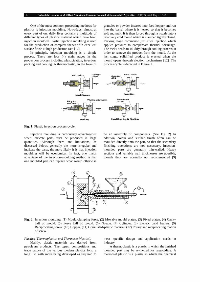
In principle, injection moulding is a simple
process. There are four (4) main stages in the
production process including plasticization, injection,
packing and cooling. A thermoplastic, in the form of
granules or powder inserted into feed hopper and run
into the barrel where it is heated so that it becomes
soft and melt. It is then forced through a nozzle into a
relatively cold mould which is clamped tightly closed.
Packing stage commence just after injection which
applies pressure to compensate thermal shrinkage.
The melts needs to solidify through cooling process in
order to remove the product from the mould. At the
last stage, solidified product is ejected when the
mould opens through ejection mechanisms [12]. The
process cycle is depicted in Figure 1.
Fig. 1: Plastic injection process cycle.
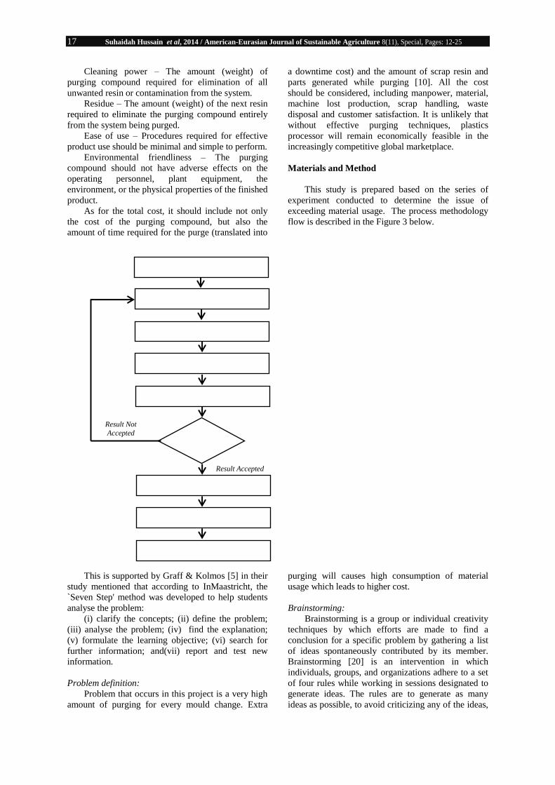
Injection moulding is particularly advantageous
when intricate parts must be produced in large
quantities. Although there are limitations, as
discussed below, generally the more irregular and
intricate the parts, the more likely it is that injection
moulding will be economical. In fact, one major
advantage of the injection-moulding method is that
one moulded part can replace what would otherwise
be an assembly of components. (See Fig. 2) In
addition, colour and surface finish often can be
moulded directly onto the part, so that the secondary
finishing operations are not necessary. Injection-
moulded parts are generally thin-walled. Heavy
sections and variable wall thicknesses are possible,
though they are normally not recommended [9]
Fig. 2: Injection moulding. (1) Mould-clamping force. (2) Movable mould platen. (3) Fixed platen. (4) Cavity
half of mould. (5) Force half of mould. (6) Nozzle. (7) Cylinder. (8) Electric band heaters. (9)
Reciprocating screw. (10) Hopper. (11) Granulated-plastic material. (12) Rotary and reciprocating motion
of screw.
Plastics (Thermoplastics and Thermoset Plastics):
Mainly, plastic materials are derived from
petroleum products. The types, compositions and
trade names of the various modern plastics form a
long list, with more being developed as required to
meet specific design and application needs in
industry.
A thermoplastic is a plastic in which the finished
moulded part may be re-melted for remoulding. A
thermoset plastic is a plastic in which the chemical

15 Suhaidah Hussain et al, 2014 / American-Eurasian Journal of Sustainable Agriculture 8(11), Special, Pages: 12-25
reaction cannot be reversed, thus allowing the part to
be cast only once. Thermoplastics are extruded,
injection-moulded, and cast in dies. Thermoset
plastics usually are compression-moulded. Some of
the thermoplastics are also formulated for thermoset
applications, such as the urethanes. [16].
Phenomenally, the quantity of plastics used
annually has been growing all over the world. Besides
its wide consumption in medical delivery systems and
healthcare applications, preservation and distribution
of food, housing appliances, communication and
electronics industry, plastics are also extensively used
in packaging, industrial and automotive applications
as well in transportation sector. Table 1 detail the uses
of plastics and recycled plastics [19] (Recycling and
Resource Recovery Council, 1994).
Table 1: Uses of plastic and recycled plastics (Recycling and Resource Recovery Council, 1994).
Name of plastic Description Some uses for virgin plastic Some uses for plastic made from
recycled waste plastic
Polyethylene terephthalate
(PET)
Clear tough plastic, may be
used as a fiber
Soft drink and mineral water
bottles, filing for sleeping bags and pillows, textiles
fibers
Soft drink bottles, (multi-layer)
detergent bottles, clear film for packaging, carpet fibers, and
fleecy jackets.
High density polyethylene
(DPE)
Very common plastic, usually
white or coloured
Crinkly shopping bags,
freezer bags, milk and cream
bottles, bottles for shampoo and cleaners, milk crates.
Compost bins, detergent bottles,
crates, mobile rubbish bins,
agricultural pipes, pallets, kerbside recycling crates
Plasticized polyvinyl chloride (PPVC)
Flexible, clear, elastic plastic Garden hose, shoe soles, blood bags and tubing
Hose inner core, industrial flooring
Low density polyethylene (LDPE)
Soft, flexible plastic Lids of ice-cream containers, garbage bags, garbage bins,
black plastic sheet
Film for builders, industry, packaging and plant nurseries,
bags
Polypropylene (PP) Hard, but flexible plastic-
many uses
Ice-cream containers, potato
crisp bags, drinking straws,
hinged lunch boxes
Compost bins, kerbside recycling
crates, worm factories
Polystyrene (PS) Rigid, brittle plastic. May be
clear, glassy
Yoghurt containers, plastic
cutlery, imitation crystal “glassware”
Clothes pegs, coat hangers, office
accessories, spools, rulers, video/CD boxes
Expanded polystyrene (EPS) Foamed, lightweight, energy absorbing, thermal insulation
Hot drink cups, takeaway food containers, meat trays,
packaging
Plastics and Transportation:
The transportation industry is the largest
consumer of engineering plastics, both as
thermoplastics and as thermosets. This industry is
also the testing ground for new products and
processes, and a leading indicator of plastics usage in
other industries. The safe and cost-effective
transportation of people and goods is vital to the
global economy. As modern modes of transportation
have evolved to meet increasing demands for safety,
environmental protection, and speed, the use of
plastics in transportation manufacturing has grown
considerably.
All forms of transportation require energy to
operate and fuel represents a significant part of
operating costs. Reducing vehicle weight be it cars,
airplanes, boats, or trains can cut fuel consumption
dramatically. Used in the service of vehicle exterior
parts, plastics are durable, do not corrode, and require
little maintenance. They allow a unique freedom of
design and the parts are fast and economical to
manufacture. In vehicle interior applications, the
various plastics fittings, such as, flooring, seats,
dashboards, and panelling maintain their attractive
appearance and are easy to clean. Durable,
lightweight, and corrosion-resistant plastics offer fuel
savings, design flexibility, and high performance at
lower costs to designers facing today‟s complex
transportation needs.
Automotive Applications Introduction:
Plastics play a major role in today‟s vehicles. The
automotive industry is the single largest end user for
many engineering plastics, such as nylons (PAs),
polycarbonate (PC), acetyl (POM), or modified
polyphenylene ether (PPE). It is also an important
market for commodity polymers (e.g., PP, PE, and
PVC). Auto makers choose plastic parts for their
durability, corrosion resistance, toughness, ease of
colouring and finishing, resiliency and light weight.
Automobile designers also discovered that plastics
solve one of their most complicated design problems:
what to do with the fuel tank. Using plastic gives
them the freedom to fit tanks into the overall concept
rather than designing around the unwieldy but
essential part.
More plastics, by volume, than steel are now
used in today‟s cars for a myriad of components. At
the end of a vehicle‟s working life, plastics
components can be recycled or the energy can be
recovered through incineration. Plastics versatility
aids the automotive industry in meeting ever more

16 Suhaidah Hussain et al, 2014 / American-Eurasian Journal of Sustainable Agriculture 8(11), Special, Pages: 12-25
stringent requirements in terms of economic
performance, safety, comfort, and environmental
considerations. Recent industry estimates expect the
use of engineering thermoplastics in exterior
automotive applications to grow by 4.8% annually
through 2011, which would equate to a total of more
than one billion lb/year. By 2012, the figure is
expected to climb to 1.3 billion lb.
Purging:
During handling and operating production, a
huge quantity of plastic resin is wasted due to product
contamination, poor resin and colour changes. As the
economic weakened, a large volume of plastic scrap
produces a major drain on the efficiency and
profitability of thermoplastic processors. This
challenging condition causes plastics processors to
introduce new management and quality enhancement
techniques, as well as a variety of new materials and
equipment.
The need for effective cleaning and purging
process of plastics processing equipment is vital to
keep productive machinery and free from problem.
There are several occasions that call for purging and
cleaning processing equipment, including colour
changes, resin changes, formulation changes, and
routine shutdown and maintenance [11].
Other problem confronting processors
encompass, increased frequency of material changes,
intensifying efforts of high quality competition, a
shortage of experienced operators, increased cost and
difficulty of waste disposal, increase in customer
demand for a wide variety of just-in-time (JIT) and
customized products. Ensuring that equipment is
cleaned thoroughly and effectively is critical for
quality control and in extending the operating life of
the machinery [11]. In addition, there is always the
need to manage bottom line costs to stay competitive
and profitable. Machine downtime is neither
competitive nor profitable to a compounder‟s
operations [11]. As a result, there are
manyopportunities at the processing area to reduce
costs by increasing the main focus on purging
operations.
It was about thirty years ago when the first
commercial purging compound appeared on the
market, but it was not until the mid-1990s that sales
for these products began rapid growth [10]. The use
of commercial purging compounds is helping
compounders meet today‟s pressures by minimizing
machine downtime and boosting productivity [11].
Commercially, many purge materials are available.
Purge materials work by one of four mechanisms [7].
Mechanical purge
Abrasive mineral filled material
Chemical purge to break down resins and
contaminants
Hard resin filled with surfactants
John [10] emphasizes purging of processing
equipment with a minimum quantity of material, in a
minimal amount of time, and at the lowest total cost
has become the most significant element to influence
the competitiveness of many processors. Table 2
contains a list of polymers and recommended purging
agents.
Table 2: Recommended Purge Materials for Various Resin Systems
Material to Be Purged Potential Purge
ABS Cast Acrylic, Polystyrene, Natural ABS, SAN
ABS/PVC General Purpose ABS (do not use FR ABS)
Acetal Polystyrene, HDPE (do not contact with PVC)
Acrylic Clean Acrylic regrind
ASA Blends Cast Acrylic, ASA, HDPE
Filled/Reinforced Resins Cast Acrylic
Fluoropolymer Cast Acrylic followed by HDPE
LCP PP
Nylon Polystyrene, Low MFI HDPE, Cast Acrylic, PP
PBT Polystyrene, HDPE, Next material to be run
Polycarbonate Cast Acrylic, Polycarbonate regrind, Polystyrene
PC/ABS Cast Acrylic, Polystyrene, HDPE
PC/PBT HDPE, Polystyrene
PEI HDPE, Glass Reinforced PC
PET HDPE, Cast Acrylic, Low MFI HDPE
Polyester Alloys HDPE
Polyolefins HDPE
PPO/PS Cast Acrylic, Polystyrene
PPS HDPE
Polysulfone Polycarbonate, Low MFI PP
Polysulfone/ABS Polycarbonate, Low MFI PP
PVC Flexible HDPE
PVC Rigid ABS, Acrylic, Polystyrene
TPE HDPE, PP
Though the total cost of the purging process must
be considered in selecting a purging compound, there
are several factors that a processor should evaluate
when choosing a purging compound [10].
17 Suhaidah Hussain et al, 2014 / American-Eurasian Journal of Sustainable Agriculture 8(11), Special, Pages: 12-25
Cleaning power – The amount (weight) of
purging compound required for elimination of all
unwanted resin or contamination from the system.
Residue – The amount (weight) of the next resin
required to eliminate the purging compound entirely
from the system being purged.
Ease of use – Procedures required for effective
product use should be minimal and simple to perform.
Environmental friendliness – The purging
compound should not have adverse effects on the
operating personnel, plant equipment, the
environment, or the physical properties of the finished
product.
As for the total cost, it should include not only
the cost of the purging compound, but also the
amount of time required for the purge (translated into
a downtime cost) and the amount of scrap resin and
parts generated while purging [10]. All the cost
should be considered, including manpower, material,
machine lost production, scrap handling, waste
disposal and customer satisfaction. It is unlikely that
without effective purging techniques, plastics
processor will remain economically feasible in the
increasingly competitive global marketplace.
Materials and Method
This study is prepared based on the series of
experiment conducted to determine the issue of
exceeding material usage. The process methodology
flow is described in the Figure 3 below.
This is supported by Graff & Kolmos [5] in their
study mentioned that according to InMaastricht, the
`Seven Step' method was developed to help students
analyse the problem:
(i) clarify the concepts; (ii) define the problem;
(iii) analyse the problem; (iv) find the explanation;
(v) formulate the learning objective; (vi) search for
further information; and(vii) report and test new
information.
Problem definition:
Problem that occurs in this project is a very high
amount of purging for every mould change. Extra
purging will causes high consumption of material
usage which leads to higher cost.
Brainstorming:
Brainstorming is a group or individual creativity
techniques by which efforts are made to find a
conclusion for a specific problem by gathering a list
of ideas spontaneously contributed by its member.
Brainstorming [20] is an intervention in which
individuals, groups, and organizations adhere to a set
of four rules while working in sessions designated to
generate ideas. The rules are to generate as many
ideas as possible, to avoid criticizing any of the ideas,
Problem definition
Brainstorming
Analysis
Improvement Identification
Monitoring
Improvement Execution
Work Standardization
Result Verification
Result
Result Not
Accepted
Result Accepted

18 Suhaidah Hussain et al, 2014 / American-Eurasian Journal of Sustainable Agriculture 8(11), Special, Pages: 12-25
to attempt to combine and improve on previously
articulated ideas, and to encourage the generation of
“wild” ideas. The goal is to determine root causes of
the problem. The techniques of brainstorming used
round table which each of the team members gives
ideas of improvement. Some of the ideas of
improvement are as follows:
i) Make a Standard Operating Procedures
(SOP) for purging process;
ii) Arrange/group mould based on material
usage;
iii) Produce material controller at the machine;
iv) Produce training for working regarding
purging process;
v) Assign a person to take in charge of purging
process;
vi) Improvement on the material of standard
packaging;
vii) Changing suction of material setting from
the autoloader;
viii) Improve the parameter setting of screw
barrel;
ix) Reduce time of purging process; and
x) Creating a counter to know amount of part
produced so that worker can know when to stop the
material going into the barrel.
At the end of brainstorming session, 3 ideas were
agreed by the group members which are (i), (iii) and
(iv).
Analysis:
The analysis is process is breaking a complex
topic or substance into smaller parts to gain a better
understanding of it. Brainstorming [20] is an
intervention in which individuals, groups, and
organizations adhere to a set of four rules while
working in sessions designated to generate ideas.
Project analysis is done by data collection of pre and
post improvement implementation. Data is collected
at every mould change at a targeted machine.
Analysis is made based on the machine production
movement. Data are taken by dividing into sections
which is number of the respective machine, purging
1, purging 2 and colour change.
Process Representation Description
Purging
1
Fig. 4: Process of Purging
1
To take out
material inside
the barrel at each
mould change
are held. The
balance of the
material inside
the barrel. It can
be reused for the
next part which
uses the same
material.
Purging
2
Fig. 5: Process of Purging
2
The process is to
clean up leftover
material inside
the barrel
(flushing the
barrel). This
process is to
ensure the next
material used
inside the barrel
will achieve the
same colour
without ruining
it.
19 Suhaidah Hussain et al, 2014 / American-Eurasian Journal of Sustainable Agriculture 8(11), Special, Pages: 12-25
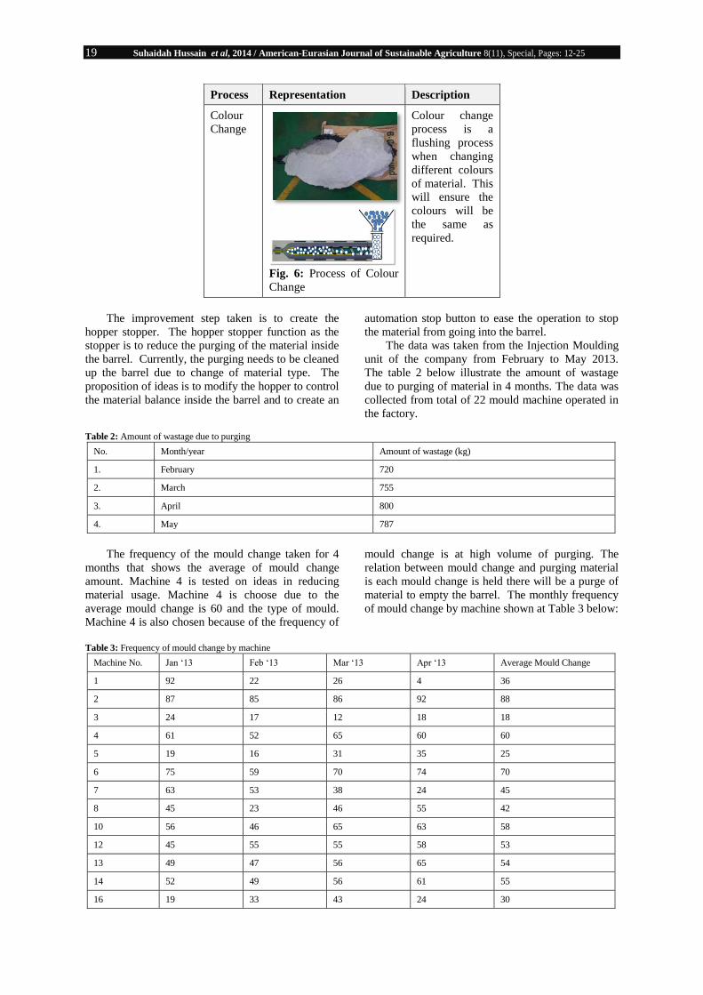
Process Representation Description
Colour
Change
Fig. 6: Process of Colour
Change
Colour change
process is a
flushing process
when changing
different colours
of material. This
will ensure the
colours will be
the same as
required.
The improvement step taken is to create the
hopper stopper. The hopper stopper function as the
stopper is to reduce the purging of the material inside
the barrel. Currently, the purging needs to be cleaned
up the barrel due to change of material type. The
proposition of ideas is to modify the hopper to control
the material balance inside the barrel and to create an
automation stop button to ease the operation to stop
the material from going into the barrel.
The data was taken from the Injection Moulding
unit of the company from February to May 2013.
The table 2 below illustrate the amount of wastage
due to purging of material in 4 months. The data was
collected from total of 22 mould machine operated in
the factory.
Table 2: Amount of wastage due to purging
No. Month/year Amount of wastage (kg)
1. February 720
2. March 755
3. April 800
4. May 787
The frequency of the mould change taken for 4
months that shows the average of mould change
amount. Machine 4 is tested on ideas in reducing
material usage. Machine 4 is choose due to the
average mould change is 60 and the type of mould.
Machine 4 is also chosen because of the frequency of
mould change is at high volume of purging. The
relation between mould change and purging material
is each mould change is held there will be a purge of
material to empty the barrel. The monthly frequency
of mould change by machine shown at Table 3 below:
Table 3: Frequency of mould change by machine
Machine No. Jan „13 Feb „13 Mar „13 Apr „13 Average Mould Change
1 92 22 26 4 36
2 87 85 86 92 88
3 24 17 12 18 18
4 61 52 65 60 60
5 19 16 31 35 25
6 75 59 70 74 70
7 63 53 38 24 45
8 45 23 46 55 42
10 56 46 65 63 58
12 45 55 55 58 53
13 49 47 56 65 54
14 52 49 56 61 55
16 19 33 43 24 30

20 Suhaidah Hussain et al, 2014 / American-Eurasian Journal of Sustainable Agriculture 8(11), Special, Pages: 12-25
17 30 62 75 89 64
18 45 26 21 42 34
20 69 52 42 56 55
21 37 8 15 18 20
22 51 38 30 39 40
In Table 4 below described the date taken before
improvement execution for all small machines. The
identified machine to reduce material usage is
machine 4. The data is then summarized based on the
average, highest and lowest amount. This is to know
which has the highest amount of purging. Highest
purging for purging 1 is 12 kg, purging 2 is 8 kg and
colour change is 25.1 kg.
Table 4: Data analysis for purging material before improvement
Machine No. Date Part Name Purging 1 (kg) Purging 2(kg) Colour Change (kg)
4 17/04/13 D46T CVR STR CLM
6.0 5.7
4 24/04/13 D46T CVR
STR CLM
4.1 4.2
4 29/04/13 P211C GLV BOX RHD
12.0 0
4 02/05/13 P211C GLV BOX RHD
4.5 3.3
4 03/05/13 P211C PNL LWR RHD
5.5 4.2
4 03/05/13 D46T FLR RR BPR
8.0 7.3 23.5
4 07/05/13 P321A IP FXG SPT
10.0 0
4 08/05/13 D46T FLR RR BPR
3.5 4.8 25.1
4 15/05/13 D46T FLR RR BPR
3.0 8.0 21.0
As data collected from the Injection Moulding of
the manufacturing company, the problem
identification process started. Ishikawa diagrams and
Why-why Analysis were implemented.
(i) Ishikawa Diagram:
Ishikawa Diagram (also called fishbone diagrams
or cause-and-effect diagrams) is diagrams that show
the causes of a certain event or problem. A common
use of the Ishikawa diagram is in product design, to
identify potential factors causing an overall effect and
to help identify the root cause of non-conformances
(www.imsworld.com). The Ishikawa Diagram for this
study illustrated below:
Fig. 7: Ishikawa Diagram of Reduction of Purging Waste Injection Moulding

21 Suhaidah Hussain et al, 2014 / American-Eurasian Journal of Sustainable Agriculture 8(11), Special, Pages: 12-25
The diagram is constructed to identify the main
problem of the project. The boxes made are to show
which problem are chosen as the main priority. The
problems are then identified by using Why-why
Analysis. There are 3 main issues targeted which is
(i) Man - absence of material controller; (ii) Machine
- material not cut off before target achieved and (iii)
Method - extra material.
Why-why Analysis
A why-why is conducted to identify solutions to
a problem that address it‟s root cause(s). Rather than
taking actions that are merely band-aids, a why-why
helps you identify how to really prevent the issue
from happening again. The Why-why analysis of the
project as shown in Table 5 below:
Table 5: Why-why analysis of Reduction of Purging Waste Injection Moulding
Problem Why 1 Why 2 Why 3
Man Less skill worker. No training provided. Absence of person to
conduct training.
No person in
charge.
Method Slider not at close position
before achieve target.
Standard of Operation
(SOP) not available.
Person in charge not
provided.
Machine No material controller. Standard machine.
Improvement Identification:
Improvement identification is made based on the
ideas that are brainstormed which can solve the
problem. Improvement is also made based on the
requirement of the project which is to reduce usage of
material and cost. In the picture shown below,
describe the improvement identification proposed for
purging 1, purging 2 and material change.
(i) Purging 1:
(ii) Purging 2:
In the purging 2, the process is to continue to run
machine wastage and to replace on oily part after
mould change. Mould setter will proceed to startup
and does not purge material if the material is the
same type. For ABS material (color material) to pp
material will need purging due to different of color
without purging it will cause the part to crack. The
Standard Operating Procedures (SOP) shows the
method of purging for mold setters which shows to
purge less material during purging 2 processes.
(i) Material Change:
In the improvement identification process, the
machine is monitored by observing the decreasing of
problem by using data collection, graphs after idea
implemented. In order to disseminate information to
all operators who is handling the injection moulding
machine, an official memo circulated to the respective
staff. In the memo stated the injection moulding cut
off material at the lock hopper before the machine
stops. The methods of cut off materials describe using
the photos for easier understanding of the operator.
Training also provided to the operator for further
understanding about the process. A total of 10
operators selected for the training. The improvement
execution has taken place by designing a new
productive machinery item where the hopper was
modified to decrease the usage of material and high
consumption of cost. Data collected after the
improvement execution in order obtain the result of
improvised machinery item.
All data related to what inspected at in the
injection moulding was collected. In the improvement
for purging 1, manual cut off hopper is needed to
ensure extra material will not fall into the barrel.
Balance of the material can be taken out from the
hopper through outlet hole and reuse for next run
without falling into the barrel. Some materials may
flow down to barrel during open slider and removing
the material. The manual hopper intention is to bring
the balance material easily.
The material will bring out from the below of the
hopper. This manual hopper is to ensure the material
does not flow into the barrel. The hopper is modified
to reduce material wastage. As such, a design and
drawing is made to specific shape of the product. The
idea of modification from manual slider to pneumatic
slider which is automation control eases the job. The
illustration below describes the movement of the
pneumatic system of the barrel and hopper before and
after.

22 Suhaidah Hussain et al, 2014 / American-Eurasian Journal of Sustainable Agriculture 8(11), Special, Pages: 12-25
Photos Description
Fig. 8: Installation of
Hopper Slider
(i) To control material
usage before complete target
with manual cut off hopper
slider. The balance material
under the hopper drops will
run until last cycle.
(ii) To remove balance
material inside hopper
through outlet hole and use
back for next run.
Note : some material flow
down to barrel during open
slider and remove material.
(average 2-3kg to barrel).
Fig. 9: Installation
pneumatic slider (auto
control)
(ii) To modify manual
slider to pneumatic slider
(auto control).
(iii) To fabricate slider
system for easy remove
material.

23 Suhaidah Hussain et al, 2014 / American-Eurasian Journal of Sustainable Agriculture 8(11), Special, Pages: 12-25
Fig. 10: S.O.P method for Purging 2
Fig. 11: Inner view of the barrel and hopper (before)
Fig. 12: Inner view of the barrel and hopper (after)
Fig. 13: Actual photos
Pneumatic
system
controller

24 Suhaidah Hussain et al, 2014 / American-Eurasian Journal of Sustainable Agriculture 8(11), Special, Pages: 12-25
Implementation of Standard Operating
Procedures (SOP) implemented in order to improve
the purging 2 process. Mould setter will proceed to
start-up and does not purge material if the material is
the same type. Abs Material (colour material) to pp
material will need purging due to different colour
without purging it will cause the part to crack.
The improvement for colour change is by using
recycle material that 80% crushes material to replace
raw material for purging.
The influence on the improvement of PIM
machine at hopper part in the initial stage of
production process has been presented in this paper.
Current method using manually has been improve via
pneumatic system as recent methodology in research
and development phase. The aim is to diminish waste
at preliminary stage of PIM process due to high
volume of production capacity as well as to reduce
cost related to material and labour.
The methodology is based on the current
manufacturing system of light duty application. In
place of these production methodologies and
techniques, the pneumatic system at the hopper (raw
material container), is the initial activity to overcome
waste issue while minimising the purge process in
the barrel involving operation of screw extruder. The
sensibility of the method, allows manufacturing time
reduction as well and associated cost for product
management. To take into account, wastage of raw
material is the common and significant issue in the
production especially companies that produces mass
production. In particular, a process in PIM
encompasses a huge volume of raw material of small
size of resin plastics. Thereby, the difference
between manually operated and pneumatic system is
defined on the basis of confronting the excessive
material usage.
This paper shows the results by consuming and
advantages gain from utilising the experiment
conducted and tools during production process.
Albeit, the methodology had produced an essential
results in the case when raw material become a waste
issue but, in general, the method could be more
extended on details approach. Therefore, the future
work on appropriate lean manufacturing concept
should be considered for the application of
determining the issue of excessive material usage.
The supporting tools of Lean Manufacturing could be
creating a novel design, innovated or fully
constructed solutions of specific components, plastic
injection process and eventually the whole
manufacturing production from raw parts to finished
goods of plastic parts.
References
1. Barrows, H.S., 1985. How to design a problem-
based curriculum for the pre-clinical years. New
York. Springer.
2. Farnsworth, C.C., 1994. Using computer
simulation in problem-based learning. In M.
Orey (Ed.), Proceedings of Thirty Fifth ADCIS
Conference, Nashville, TN : Omni Press, pp:
137-140.
3. Five Whys analysis, a why-why is based on a
Japanese quality technique and its description by
quality consultant Peter Scholtes. See Peter
Senge‟s ”The Fifth Discipline Fieldbook.”
4. Fuller, R., 1998. Encouraging active learning at
university. HERDSA news, 20(3): 1-5.
5. Graff Erik, D., and A. Kolmos, 2003.
Characteristics of Problem Based Learning,
International Journal Engineering Education,
19(5): 657-662.
6. Barrows, H.S., 1984. A specific problem-based,
self-directed learning method designed to teach
medical problem-solving skills, and enhance
knowledge retention and recall, in H. G. Schmidt
and M. L. de Volder (eds.), Tutorials in
Problem-Based Learning, Van Gorcum, Assen,
the Netherlands, pp: 16±32.
7. Harold, F., Jr. Giles, R. John, Jr. Wagner, M.
Eldridge, 2005. Mount. Screw Cleaning and
Purge Compounds, Extrusion, pp: 365-372.
8. Herron, C., C. Hicks, 2008. The transfer of
selected lean manufacturing techniques from
Japanese automotive manufacturing into general
manufacturing (UK) through change agents,
Journal of Robotics and Computer-Integrated
Manufacturing, 24: 524-531.
9. James, G., 1999. Bralla. Design for
Manufacturability Handbook, Second Edition.
Injection-Molded Thermoplastic Parts, Chapter
(McGraw-Hill Professional); Access
Engineering.
10. John Pizzo, 2009. Using Purging Compound to
Streamline Production Costs and Reduce Waste,
Sun Plastech Inc. Production Spring.
11. Komarmi, J.J., 2002. Purging compounds reduce
machine downtime and increase productivity for
compounders, Journal of Plastics, Additives and
Compounding, 4(10): 14-16.
12. Kemal Karasu, M., Mehmet Cakmakci, Merve
B. Cakiroglu, ElifAyva, 2014. NeslihanDemirel-
Ortabas. Improvement of changeover times via
Taguchi empowered SMED/case study on
injection molding production, Journal of
Measurement., 47: 741-748.
13. Mat Salleh, M., M.Z.M. Zain, 2012. The Study
of Lean Layout in an Automotive Parts
Manufacturer, Journal of Applied Mechanics
and Materials., 110-116: 3947-3951.
14. Muslimen, R., S.M. Yusof and ASZ. Abidin,
2011. A Case Study of Lean Manufacturing
Implementation Approach in Malaysian
Automotive Components Manufacturer,
Electrical Engineering and Intelligent Systems,
Springer New York, pp: 327-335.

25 Suhaidah Hussain et al, 2014 / American-Eurasian Journal of Sustainable Agriculture 8(11), Special, Pages: 12-25
15. Norman, G.R. and H.G. Schmidt, 1992. The
psychological basis of problem-Based Learning:
A review of the Evidence. Academic Medicine,
67(9): 557-565.
16. Ronald, A., 2006. Walsh. McGraw-Hill
Machining and Metalworking Handbook, Third
Edition, McGraw-Hill: The McGraw-Hill
Companies, Inc.
17. Rosato, Donald V. Plastics End Use
Applications, Springer, 2011. Edition Series:
Springer Briefs in Applied Sciences and
Technology, (5): 49-50.
18. Ahmad Fakhri S. et al., 2012. The
Implementation of Lean Manufacturing in
Malaysian Automotive Industry, Advanced
Materials Research, 576: 731.
19. Al-Salem, S.M., P. Lettieri, J. Baeyens, 2009.
Recycling and recovery routes of plastic solid
waste (PSW): A review, Journal of Waste
Management., 29: 2625-2643.
20. Osborn, A.F., 1957. Applied imagination. New
York: Scribner.
21. Vernon, D.T.A. and R.L. Blake, 1993. Does
problem-based learning work? A meta-analysis
of evaluative research. Academic Medicine,
68(7): 550-563.
22. Gijselaers, W.H., 1996. Connecting problem-
based practices with educational theory, in L.
Wilkerson and W. H. Gijselaers (eds.), Bringing
Problem-Based Learning to Higher Education:
Theory and Practice, Jossey-Bass Publishers,
San Francisco.