amended reclamation plan for rosemary’s mountain … · amended reclamation plan . for ....
TRANSCRIPT

AMENDED RECLAMATION PLAN FOR
ROSEMARY’S MOUNTAIN QUARRY CA Mine ID # 91-37-0066
PDS2013-MUP-87-021W2 and PDS2013-RC-87-001W2
Prepared for:
Granite Construction Company, Inc. 5606 Pala Road
Fallbrook, CA 92028
Original Plan Prepared by:
Brian F. Mooney Associates 9903-B Business Park Avenue San Diego, California 92131
(P87-021, RP87-001, Log #87-2-13)
September 1996
Amended by:
3511 Camino Del Rio South, Suite 403
San Diego, CA 92108 619-284-8515, Fax 619-284-0115
Revised July 17, 2014

i
Table of Contents
OWNER, OPERATOR, AND AGENT ....................................................................... 1
1. Applicant .............................................................................................................. 1
2. Name (if any) of mineral property .......................................................................... 1
3. Property owners or owners of surface rights (list all owners) ................................. 1
4. Owners of mineral rights ...................................................................................... 1
5. Lessee ................................................................................................................... 1
6. Operator ............................................................................................................... 1
7. Agent of process ................................................................................................... 1
8. Brief description, including legal, of the extent of the mined lands (to be) involved
by this operation, including total acreage ................................................................. 2
9. Describe the access route to the operation site ..................................................... 2
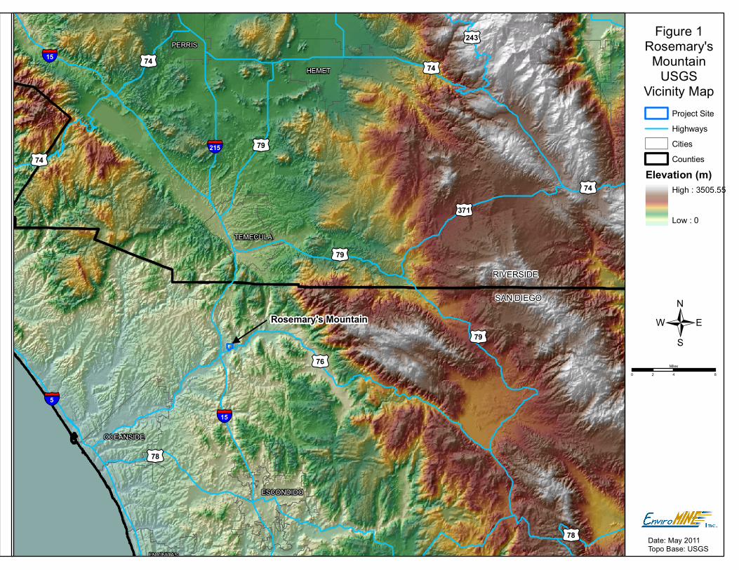
10. Attach location and vicinity map ......................................................................... 2
11. Mineral commodity (to be) mined ........................................................................ 2
12. Geologic description, including brief general geologic setting, more detailed
geologic description of the mineral deposit (to be) mined, and principal minerals or
rock type present ...................................................................................................... 2
13. Brief description of environmental setting of the site and surrounding areas.
Describe existing area land use, soil, vegetation, ground water elevation and surface
water characteristics, average annual rainfall and/or other factors pertaining to
environmental impacts and their mitigation and reclamation ................................... 5
SURFACE MINING OPERATION ............................................................................ 7
14. Proposed starting date of operation ..................................................................... 7
15. Operation Termination Date ............................................................................... 7
16. Reclamation Plan and Major Use Permit Area ..................................................... 7
17. Anticipated production ....................................................................................... 7

ii
18. Mining method .................................................................................................. 7
19a. If processing of the ore or minerals mined is planned to be conducted at or
adjacent to the site, briefly describe the nature of the processing and explain
disposal method of the tailings or waste from processing ........................................ 10
19b. Estimate quantity (gallons per day) and quality of water required by the
proposed operation, specifying proposed sources of this water, of method of its
conveyance to this property and the quantity and method of disposal of used and/or
surplus water ......................................................................................................... 11
20. If the nature of the deposit and the mining method used will permit, describe
and show the steps or phases of the mining operation that allow concurrent
reclamation, and include a proposed time schedule for such concurrent activities . 11
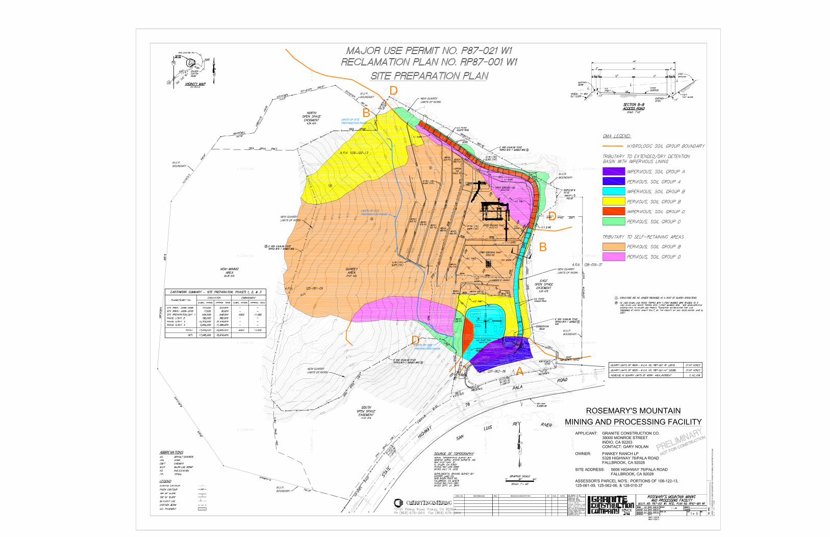
21. Attach a map of the mined lands and/or suitable aerial photograph showing ... 11
RECLAMATION PLAN ......................................................................................... 12
22. Indicate on an overlay of map of item 21, or by color or symbol on map those
areas to be covered by reclamation plan ................................................................. 12
23. Describe the ultimate physical conditions of the site and specify proposed use(s)
of the mined lands as reclaimed ............................................................................. 12
24. Describe relationship of the interim uses other than mining and the ultimate
physical condition to ............................................................................................... 17
25. Provide evidence that all owners of a possessory interest in the land have been
notified of the proposed use(s) or potential uses identified in item 22. (Attach copy of
notarized statement of acknowledgement, etc.) ....................................................... 17
26. Describe soil conditions and proposed soil salvage plan .................................... 17
27. Describe the methods, their sequence and timing, to be used in bringing the
reclamation of the land to its end state. Indicate on map (This may be indicated
directly on plot plan or on a separate attachment to applications). Include
discussion of the pertinent items listed below ......................................................... 17
28. If applicant has selected a short term phasing of his reclamation, describe in
detail the specific reclamation to be accomplished during first phase ..................... 22

iii
29. Describe how reclamation of this site in this manner may affect future mining at
this site and in the surrounding area...................................................................... 22
30. Statement of Responsibility .............................................................................. 22
List of Figures Figure 1. Project Location .……………………………………………………........ 3 Figure 2. Project Vicinity ………………………………………………………….... 4 List of Tables Table 1. Hydroseed Mix…………………………………………………………….. 14 List of Attachments
Attachment A. Revegetation Plan Attachment B. Storm Water Notice of Intent Attachment C. Detention Basin Design Attachment D. Plot Plan

1
COUNTY OF SAN DIEGO ROSEMARY’S MOUNTAIN QUARRY RECLAMATION PLAN AMENDMENT
OWNER, OPERATOR, AND AGENT: 1. Applicant: Granite Construction, Inc. c/o Gary Nolan 5606 Pala Rd, (Highway 76) Fallbrook, California 92028 (760) 731-0694 _____________________________________________________________________________________ 2. Name (if any) of mineral property: None _____________________________________________________________________________________ 3. Property owners or owners of surface rights (list all owners): Pankey Ranch 5328 Highway 76 Bonsall, California 92003 _____________________________________________________________________________________ 4. Owners of mineral rights: Same as above _____________________________________________________________________________________ 5. Lessee: Granite Construction, Inc _____________________________________________________________________________________ 6. Operator: Same as applicant _____________________________________________________________________________________ 7. Agent of process: EnviroMINE, Inc., 3511 Camino Del Rio South, Suite 403, San Diego, CA 92108 _____________________________________________________________________________________

2
8. Brief description, including legal, of the extent of the mined lands (to be) involved by this operation, including total acreage: The proposed rock quarry project is located in the Pala area of northern San Diego County, approximately 1.25 miles east of Interstate 15. The irregularly shaped project site is situated north of SR-76 (Pala Road). Shearer Crossing and Couser Canyon Road lie to the west and east, respectively.
TRA 57028 Assessor's Book 108, 125. Page 122, 061. That portion of the East Half of Section 36, Township 9 South, Range 3 West, San Bernardino Meridian, according to official Plan thereof; that portion of the Monserate Rancho, according to Map thereof on file in the office of the Recorder of San Diego County in book 1, page 108 of Patents all in the unincorporated area of the County of San Diego, State of California. Total acreage of the project is approximately 103.63 acres with approximately 48.32 acres used for mining and processing. ____________________________________________________________________________________ 9. Describe the access route to the operation site: Access to the site is provided from Pala Road/SR 76 approximately 1.25 miles east of the intersection with Interstate 15. This section of the highway was widened and re-aligned in 2008. Pala Road lies adjacent to the site's southern boundary. It is currently an east-west, three-lane, rural highway from I-15 to the entrance of the quarry. The County of San Diego has designated this highway as a major road (four lanes, divided) east of I-15. _____________________________________________________________________________________ 10. Attach location and vicinity map: See Figures 1 and 2 _____________________________________________________________________________________ 11. Mineral commodity (to be) mined: Rock to be crushed for use in concrete and asphalt production and for road base. _____________________________________________________________________________________ 12. Geologic description, including brief general geologic setting, more detailed geologic description of the mineral deposit (to be) mined and principal minerals or rock type present: The proposed mining site is located at the southern end of the Monserate Mountains within the Peninsular Range of Southern California. Directly south of the site lies the east-west trending San Luis Rey River Valley. Soil, slope wash and disintegrating boulders comprise the surficial materials of the site. Bedrock consists of granitic igneous rock which intruded the once-overlaying rock approximately 110 million years ago. The following principal rock types are found at the site:
ENCINITAS
PALMSPRINGS
OCEANSIDE
PERRIS
HEMET
POWAY
TEMECULA
ESCONDIDO
Figure 1Rosemary's
MountainUSGS
Vicinity Map
/£¤76
Project SiteHighwaysCitiesCounties
Elevation (m)High : 3505.55
Low : 0
Date: May 2011Topo Base: USGS
§̈¦15
§̈¦15
§̈¦215
£¤78
§̈¦5
£¤74
£¤243
£¤74
£¤371
£¤79
£¤74
£¤79
£¤74
£¤78
£¤79
SAN DIEGO
RIVERSIDE
Rosemary's Mountain
0 4 82Miles

Figure 2Rosemary's
MountainUSGS
Vicinity Map
/
Project Site
Date: May 2011Topo Base: USGS
Realigned SR-76
Project Site
0 1,000 2,000500Feet
5
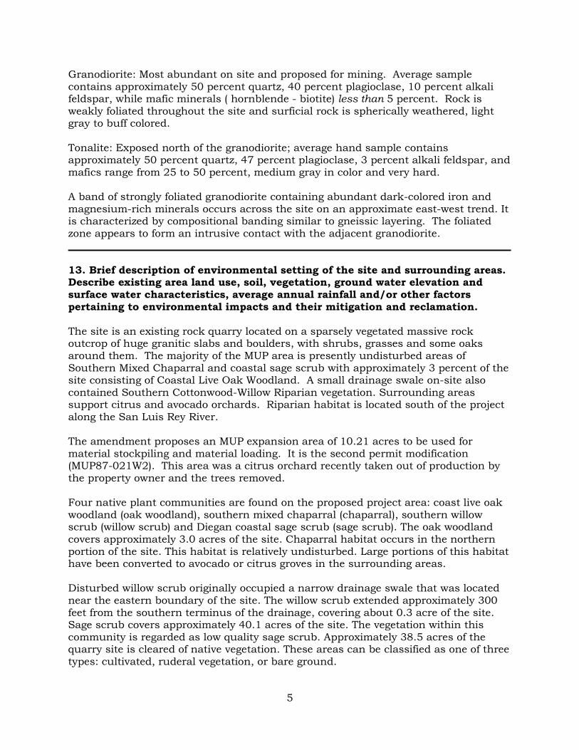
Granodiorite: Most abundant on site and proposed for mining. Average sample contains approximately 50 percent quartz, 40 percent plagioclase, 10 percent alkali feldspar, while mafic minerals ( hornblende - biotite) less than 5 percent. Rock is weakly foliated throughout the site and surficial rock is spherically weathered, light gray to buff colored. Tonalite: Exposed north of the granodiorite; average hand sample contains approximately 50 percent quartz, 47 percent plagioclase, 3 percent alkali feldspar, and mafics range from 25 to 50 percent, medium gray in color and very hard. A band of strongly foliated granodiorite containing abundant dark-colored iron and magnesium-rich minerals occurs across the site on an approximate east-west trend. It is characterized by compositional banding similar to gneissic layering. The foliated zone appears to form an intrusive contact with the adjacent granodiorite. _____________________________________________________________________________________ 13. Brief description of environmental setting of the site and surrounding areas. Describe existing area land use, soil, vegetation, ground water elevation and surface water characteristics, average annual rainfall and/or other factors pertaining to environmental impacts and their mitigation and reclamation. The site is an existing rock quarry located on a sparsely vegetated massive rock outcrop of huge granitic slabs and boulders, with shrubs, grasses and some oaks around them. The majority of the MUP area is presently undisturbed areas of Southern Mixed Chaparral and coastal sage scrub with approximately 3 percent of the site consisting of Coastal Live Oak Woodland. A small drainage swale on-site also contained Southern Cottonwood-Willow Riparian vegetation. Surrounding areas support citrus and avocado orchards. Riparian habitat is located south of the project along the San Luis Rey River. The amendment proposes an MUP expansion area of 10.21 acres to be used for material stockpiling and material loading. It is the second permit modification (MUP87-021W2). This area was a citrus orchard recently taken out of production by the property owner and the trees removed. Four native plant communities are found on the proposed project area: coast live oak woodland (oak woodland), southern mixed chaparral (chaparral), southern willow scrub (willow scrub) and Diegan coastal sage scrub (sage scrub). The oak woodland covers approximately 3.0 acres of the site. Chaparral habitat occurs in the northern portion of the site. This habitat is relatively undisturbed. Large portions of this habitat have been converted to avocado or citrus groves in the surrounding areas. Disturbed willow scrub originally occupied a narrow drainage swale that was located near the eastern boundary of the site. The willow scrub extended approximately 300 feet from the southern terminus of the drainage, covering about 0.3 acre of the site. Sage scrub covers approximately 40.1 acres of the site. The vegetation within this community is regarded as low quality sage scrub. Approximately 38.5 acres of the quarry site is cleared of native vegetation. These areas can be classified as one of three types: cultivated, ruderal vegetation, or bare ground.

6
No sensitive plant species was observed on the site. The status of the three, sensitive, plant species reported in the project vicinity have been updated: thread-leaved brodiaea is a Federal Candidate Category 1 species, is listed by the state as endangered and is also a California Native Plant Society (CNPS) List IB species. Lakeside lilac is a Federal Candidate Category 2 species and is a CNPS List IB species. Orcutt's dudleya is a Federal Candidate Category 2 species as well as a CNPS List 2 species. Sensitive wildlife species include the designation of critical habitat for the least Bells vireo (vireo). The coastal California gnatcatcher (gnatcatcher} inhabits sage scrub. However, no gnatcatchers were observed 'during focused surveys in 2011 or 2013. The 2013 MUP Amendment area consist of approximately 10.21 acres of an abandoned citrus grove located at the northern end of the project area. Although no arroyo toads were detected on the project site, a juvenile was observed approximately 1,000 feet southeast of the project site adjacent to the San Luis Rey River during a habitat suitability survey conducted for the proposed project in July 1995. This habitat suitability study further determined that appropriate habitat does not exist on the project site, inclusive of the drainage swale area located north of SR-76 near the eastern edge of the site. Mitigation for impacts to sensitive habitats has included a combination of preservation and revegetation at several sites adjacent to and within the vicinity of the project site. The oak woodland has been mitigated by dedicating the woodland outside the mining_ area but within the Major Use Permit (MUP) to open space and dedicating a hillside south of the San Luis Rey River that supports oak woodland to open space. Most of the chaparral at the quarry site was dedicated as open space. Direct impacts to southern willow scrub and vireo critical habitat, and indirect impacts to vireo habitat have been mitigated by dedication of open space and revegetation off site. The project also completed some riparian plantings along the SR-76 slope bank and adjacent streambed. The impact to 27.3 acres of sage scrub is mitigated by the preservation of 54.6 acres of sage scrub both on and off-site, including the non-impacted on-site sage scrub. There will be no additional biological impacts as a result of this MUP modification. The added area to the permit area is disturbed and was a former citrus grove. This grove was recently abandoned and the trees removed by the property owner. The Soil Conservation Service (now the National Resource Conservation Service) mapped the soil on the mine as Cieneba very rocky coarse sandy loam, 30 -75% slopes. Soils in this mapping unit are well drained to excessively drained, very shallow to shallow, rocky to very rocky soils with slopes between 9 to 75 percent. The surface layer ranges from coarse sandy loam to silt loam and depth to bedrock is 3 to 17 inches. These soils have low to very low fertility and an available water holding capacity from less than 0.5 inch to 2 inches. The San Luis Rey River passes just south of the mining project. No mining activity will take place in the riverbed. Surrounding land consists mainly of open space and agriculture. The residential density is very low in this part of the San Luis Rey River Valley.

7
Since the peak of the proposed site is approximately 650 feet above the river and the proposed quarry will be in solid rock, the project will not affect the groundwater characteristics in the area. The mean annual precipitation for the site is 13.7 inches. The mean rainfall occurring from Pacific storms in the months of November through April. All surface runoff from the proposed site drains into the San Luis Rey River. _____________________________________________________________________________________ SURFACE MINING OPERATION: 14. Proposed starting date of operation:
Quarry Approved: October, 2002 Project Began: 2008 Estimated life of operation: 40 years Duration of Site Preparation: 2008 -2017
_____________________________________________________________________________________ 15. Operation Termination Date:
Developed In Operation Terminated: October 9, 2048
16. Reclamation Plan and Major Use Permit Area:
Reclamation Plan area: 48.26 acres Major Use Permit Area: 103.52 acres
_____________________________________________________________________________________ 17. Anticipated production:
Annual production: 1,100,000 tons/yr Life of mine production: 24,000,000 tons Waste retained on site: None anticipated Waste disposal off site: None anticipated Maximum anticipated depth: 610 ft. (elevations: 915 feet to 305 feet)
_____________________________________________________________________________________ 18. Mining method: (Check all applicable)
Open Pit _X_ Single Bench ____ Quarry: Hill Top ____ Multibench _X_ Side Hill _X_
Dragline ____ Low Level ____ Shovel ____ Underground ____ Gravel Bar Skimming ____ Gravel/Sand Pit ____ Drill and Blast _X_

8
Clay Top ____ Truck to Processing ____ Plant (to RR) ____
Borrow Pit ____ Tailing Pond ____ Slurry Pump ____
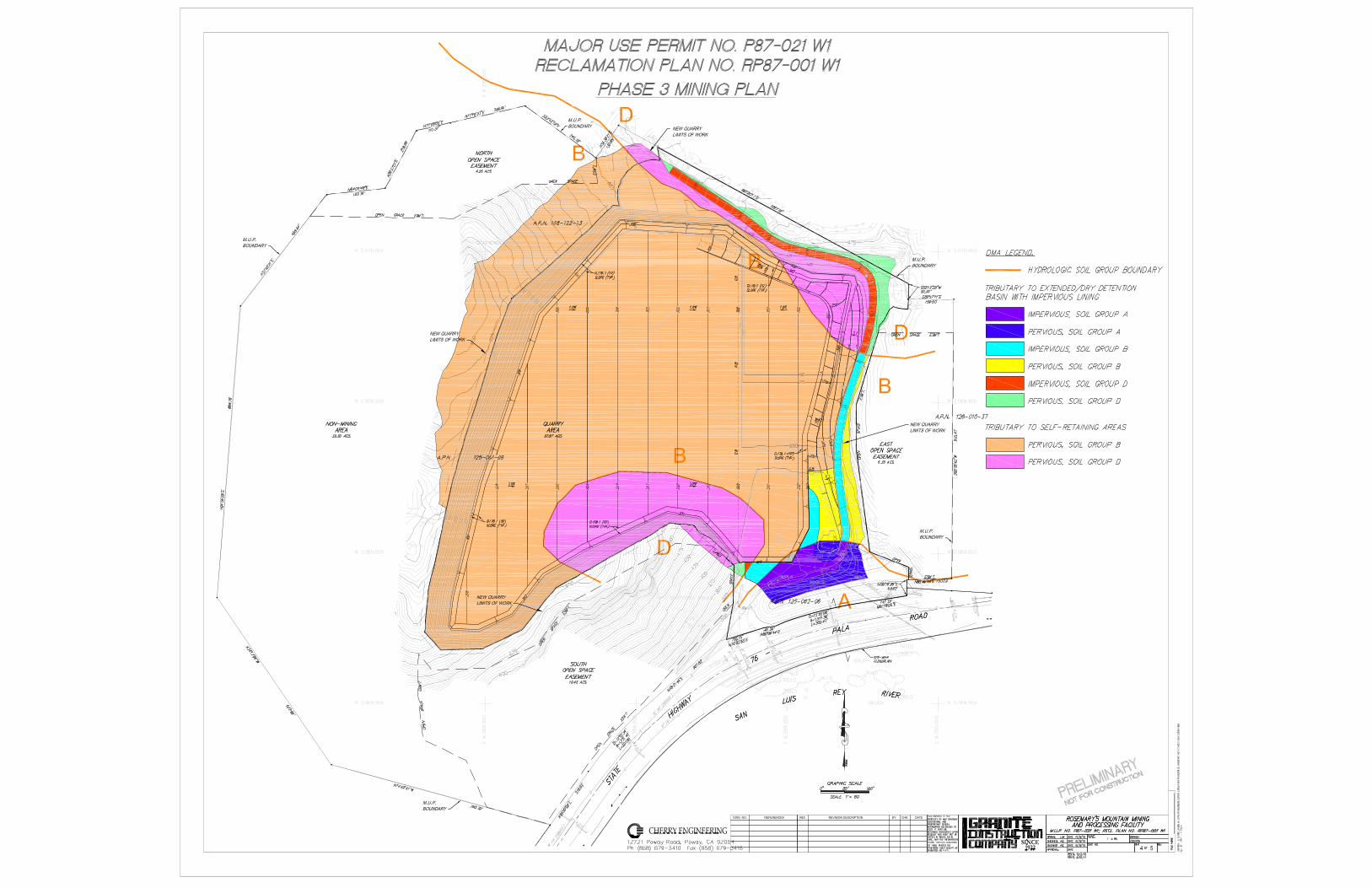
Mining will take place over a period of approximately 40 years. Movable uses include a hydraulic excavator, front end loaders, haul trucks, water trucks, metal storage containers, small offices, and equipment storage yards. Mining occurs in three generally defined phases after initial site preparation. Initial site preparation included the relocation and widening of Highway 76, the removal of overburden for the construction of Highway 76 and the preparation of the pad site for the construction of the permanent aggregate, asphalt, and concrete plants, and the use of the necessary equipment to process this material. The first phase of the quarry operation includes excavating the initial cut of the mountain beginning at 915 feet above mean sea level down to approximately 825 feet above sea level. The second phase continues mining down to approximately 375 feet above mean sea level. Both of these phases will generally occur west of the asphalt and concrete plants. Phase 3 of mining will occur north of these plants and will be the final mining phase. Permanent structures for the asphalt and concrete plants must be complete before phase 1 mining begins. Mining would begin by drilling and blasting along the eastern facing slope working down from elevation 915 AMSL and working below the ridge line thereby minimizing the visual impact. Mining activities would begin at an elevation of approximately 915 feet AMSL and would be conducted from the top down and from south to north along the face being worked. The mining plan is designed for continuous operation (i.e. while one section is being drilled, the adjacent section will be scaled and loaded and the third section will be prepared for mining) with the exception of blasting which would be limited to once a week. The working face would have a maximum height of 33 feet and a minimum width of 66 feet, creating an interim benched slope configuration of 2:1 as mining proceeds downward at approximately 33 foot intervals. The interim benches enable experienced mine managers and engineering staff to make weekly inspections of high wall stability and loose ground. Inspection of the mining face by mine personnel may be more frequent as needed, depending on the field conditions. A Registered Engineering Geologist or Geotechnical Engineer will conduct a quarterly inspection for rock stability. Results of the quarterly inspections will be included in the annual report. Based on available geotechnical information, no gross stability problems are anticipated. However, if fracture and/or joints mapped by the engineer and/or geologist indicate potential future wedge type of failures that cannot be contained by wire mesh, rock anchors would be used to stabilize them. In addition, local isolated benches may be left in place in areas where geotechnical conditions warrant. Benches would then serve as staging areas for rock anchoring operation. The local benches, if any, are not likely to be continuous because they would be needed only to enhance local stability. These benches would be sculpted to appear as natural rock ledges and would add additional variation to the face.

9
Blasting will be done approximately once a week between the hours of 11:00 am and 3:00 pm, Monday through Friday, by a licensed blasting contractor. Blasting is not permitted on Saturdays. The blasting contractor will bring all dynamite charges and blasting caps to the site for each day's work. No blasting material would be stored overnight on the site. Once a working face has been blasted, the loosened material will be moved by a hydraulic excavator into haul trucks and transported to the primary crusher. After initial crushing to approximately 6-inch size, a conveyor will move the rock to the plant on the upper pad to begin the secondary crushing, screening and mixing process (Attachment E. Plot Plan). The overall plant layout is shown on the major use permit plot plan. The primary crusher will be located in the north central portion of the mine area at an approximate elevation of 655 feet amsl during the Site Preparation Phase and Mining Phase 1. As excavation continues into Mining Phase 2, the primary crusher and conveyor will be moved to various elevations of the pit to accommodate excavation in specific areas. It will continue to be utilized in conjunction with the conveyor to move rock to the crushing and screening plant on the 490 Pad. This will reduce the number of truck trips required to move the ore to the primary crusher, decrease crowding of equipment and improving safety conditions. The truck weigh scales and aggregate loading silos will be located adjacent to the crushing/ screening plant on the 490 pad. A mechanically stabilized earth (MSE) wall will be placed between the mid and upper level pads where a 1:1 slope is planned during Phases 1and 2. In compliance with MSHA, rock berms or K-rail will be placed on the upper pad along the top edge of any drop off from the pad. At the completion of Phase 2, the crushing and screening equipment, equipment enclosures and aggregate loading silos will be moved to the pit bottom for the last phase of mining. During Phase 3, the MSE wall will be removed and the 1:1 overburden slope graded to a final slope of 2:1 with a slope face of approximately 70 linear feet. A bench, six foot wide, will be placed across the face of the final 2:1 slope at a maximum 30 foot vertical interval as an erosion control management practice. This bench will be constructed with a swale or ditch to direct drainage in a cross slope direction to a stable outfall. The swale or ditch shall be at least one foot deep at a minimum grade of 2%. Concrete lining is not necessary as indicated in the geotechnical report. It should be noted that the bench and slopes will also be vegetated. The bench is designed in compliance with the grading ordinance requirements for benches (Section 87.402). Slope stability analysis of the final slopes indicate the 1:1 H:V excavations and proposed final fill slope of 2 H:V will have an adequate factor of safety in respect to global stability. Factors of safety for these slopes are indicated in the Geotechnical Report as being higher than the County standard of 1.5 for static and 1.1 for pseudo-static conditions. These factors of safety meet the requirements of the County of San Diego’s Grading Ordinance. This will leave a generally, flat area in the northern area of the project site that will be reclaimed as open space/undeveloped land. Near the end of Mining Phase 2, the primary crusher plus the crushing and screening plant with enclosures will be moved to the same location at the bottom of the pit. This will allow mining of the pads in Phase 3. Mining to final elevations will occur during

10
Mine Phase 3. Internal quarry haul roads will move as needed to provide efficient access to the primary crusher. The 6-inch rock will be sent over a screen and into the top of the cone crushers. These crushers will be mounted on steel or reinforced concrete platforms and be 12 to 14 feet in total height. The crushed rock will be discharged out the bottom of the cone crushers and onto another conveyor for transport onto a triple-deck vibrating screen where 11/2-inch, 3/8-inch, 3/4-inch and fine material will be sorted and conveyed to loading hoppers and to storage piles. The screens and loading bins will be 25 to 30 feet in height to permit drive-under loading of haul trucks. Oversize rock rejected by the screens will be conveyed to a "shorthead" cone crusher to be further reduced and returned to the screens. The Plot Plan (Attachment E.) shows the facility layout. The hours of operation for mining and rock crushing shall be between 7:00 a.m. and 6:00 p.m., Monday through Friday. Sales of aggregate, concrete and asphalt will be conducted from 7:00 am to 10:00 pm, Monday through Friday, and from 7:00 am to 1:00 pm on Saturdays. The site will be closed on Sundays. The asphalt plant may operate between 10:00 p.m. and 7:00 a.m. on an as-needed basis as long as the exterior noise level does not exceed 45 dB at any residential building site or other noise sensitive location which may be developed in the future. In order to reduce the effect of road construction on commuter traffic, much of the highway work is conducted between the hours of 8:00 pm and 6:00 am. Night lighting will be installed around the batch plants and at strategic locations around the site. Lighting will be designed to minimize glare and reflection onto neighboring areas. Generally, pole-mounted sodium, metal halide, or fluorescent lighting will be employed. Such lighting minimizes energy use, and in combination with cut-offs, reduces light pollution. Trash will be placed in disposal bins located in the plant area. Small equipment and tools will also be stored in this designated area. Heavy equipment will be stored on the 490 Pad. A 30 foot high berm has been built near the main access road to the mine to shield the operations from the view of motorists on Highway 76. This berm has been landscaped. In addition, the 6-foot high chain link fence shall be extended around the perimeter of the mine area to include the haul road on the northern edge of the site. ___________________________________________________________________________________ 19a. If processing of the ore or minerals mined is planned to be conducted at or adjacent to the site, briefly describe the nature of the processing and explain disposal method of the tailings or waste from processing. Crushed rock will be conveyed to on-site concrete and asphalt batch plants, where it will be mixed with imported sand and cement for concrete; and with sand and oil products for asphalt. No unusable tailings or waste from processing will occur.

11
19b. Estimate quantity (gallons per day) and quality of water required by the proposed operation, specifying proposed sources of this water, of method of its conveyance to this property and the quantity and method of disposal of used and/or surplus water. Approximately 65,000 gallons of water per day will be used for dust control, concrete production and landscaping. Water will be purchased from existing Pankey Ranch wells adjacent to the site. Runoff will be retained in a sediment basin and exit through a riser pipe into the San Luis Rey riverbed. Water will also be pumped from the basin for re-use in dust control; so very little off-site run-off is anticipated. _____________________________________________________________________________________ 20. If the nature of the deposit and the mining method used will permit, describe and show the steps or phases of the mining operation that allow concurrent reclamation, and include a proposed time schedule for such concurrent activities. The proposed mining method calls for continuous mining which would allow for concurrent reclamation of the mining face. During final blasting, the mining face shall be "sculpted" to create natural looking ledges, nooks and crannies. To avoid the horizontal lines typically associated with hard rock quarries, the ledges shall be irregular and no larger than 6-12 feet in width. However, to meet slope stability recommendations at the time of final grading, some segments of the original benches may be left in place. The ledges should also be angled toward the rock face to trap and retain soil on the ledges. Approximately 6-12 inches of soil type material would be installed on the ledges and smaller amounts would be installed within the nooks and crannies. A hydroseed mix shall then be applied to those areas capable of supporting vegetation. If the hydroseed does not germinate after the first rainy season, a temporary irrigation system would be installed to ensure establishment of the vegetation. This irrigation system would be an overhead spray system that could be attached to the wire mesh. With the above mentioned measures, approximately 5-10 percent of the mining face would be vegetated. However, it is the proposed combination of rock sculpting, rock staining and landscaping that would ultimately create a natural looking mined face. The applicant has constructed a 30 foot high berm, with landscaping, at the entrance of the mining plant and off-site revegetation during the site preparation phase of project start-up as mitigation for biological and visual impacts. _____________________________________________________________________________________ 21. Attach a map of the mined lands and/or suitable aerial photograph showing: The following information has been provided on the attached Plot Plan (Attachment D). (a) Boundaries and topographic details of the site; (b) Location of all streams roads, railroads, water wells, and utility facilities within 500 feet of the site;

12
(c) Location of all currently proposed access roads to be used in conducting the surface mining operation(s); (d) Location of area (to be) mined, and of waste dumps and tailing ponds; (e) By use of overlay symbol or color, depiction of separate mining phases if applicable; (f) Topography and cross-sections of excavation following reclamation. _____________________________________________________________________________________
RECLAMATION PLAN
22. Indicate on an overlay of map of item 21, or by color or symbol on map those areas to be covered by reclamation plan. The entire Reclamation Plan area is covered by the MUP. See Attach D: Plot Plan _____________________________________________________________________________________ 23. Describe the ultimate physical conditions of the site and specify proposed use(s) of the mined lands as reclaimed. The reclaimed use for the quarry will be open space after Reclamation Plan closure. The mining face shall be "sculpted" to create natural looking ledges, nooks and crannies. To avoid the horizontal lines typically associated with hard rock quarries, the ledges shall be irregular and no larger than 6-12 feet in width. However, to meet slope stability recommendations at the time of final grading, some segments of the original benches may be left in place. The ledges should also be angled toward the rock face to trap and retain soil on the ledges. Approximately 6-12 inches of soil type material would be installed on the ledges and smaller amounts would be installed within the nooks and crannies. Flat areas accessible to large equipment will be ripped to two feet of depth to loosen the surface and relieve any compaction. A hydroseed mix shall then be applied to those areas capable of supporting vegetation. If the hydroseed does not germinate after the first rainy season, a temporary irrigation system would be installed to ensure establishment of the vegetation. This irrigation system would be an overhead spray system that could be attached to the wire mesh. The Revegetation Plan is provided as Attachment A. Available topsoil materials were salvaged from the flatter areas in the initial development of the site and were utilized to comply with the required landscaping plan, primarily on the berm and near the entrance to the site.. Soil in the 2013 amendment area is mapped as a Cieneba very rocky coarse sandy loam that is shallow to very shallow in depth on steep to very steep, rocky slopes. Fertility of this material is low. Numerous roads had been previously cut through this area for use in agricultural operations. This area was also substantially disturbed during the removal of the former citrus grove by bulldozing the entire area. As a result, any topsoil that may

13
have been available has been mixed with overburden and as a result no material from this area will be salvaged. Top dressing materials to be utilized for revegetation will consist of quarry fines or imported amendments which will be analyzed to determine the presence of elements essential for plant growth prior to seeding. Quarry fines will be stored on Pad 490 until the crushing and screening plants are moved to the Quarry floor in Phase 3. In Phase 3, enough overburden and quarry fines will be stockpiled near the crusher to cover any exposed hard rock to a depth of 12 inches on the pit floor during final reclamation. If the soil analysis shows that fertility levels or material constituents are inadequate to successfully implement the revegetation program, fertilizer or other soil amendments may be incorporated into the material through direct broadcasting, hydroseeding, or may be injected into irrigation waters, if used. A number of roads utilized by the property owner were in existence prior to the mine operation. All internal roadways that the property owner wishes to be left in place will not be reclaimed. All other roads will be graded to match the surrounding contours, ripped to relieve compaction and hydroseeded. Drainage from the site would be similar to the conditions developed during the operational phases of the project. A detention pond, designed to trap sediment and prevent impact to the San Luis Rey River, is located in the extreme southeast corner of the excavation area and would remain in place. This pond is to be connected to a culvert running beneath SR 76. This pond and culvert will remain in place after mining is completed and will be left as part of the final reclamation. Groundwater is not expected to be encountered during this project. (a) Revegetation Objectives The objective of the revegetation plan is to provide vegetative cover for final slopes controlling erosion and stabilizing slopes, using plant materials capable of self-regeneration without continued dependence on irrigation, soil amendments or fertilizer. Revegetation will be sufficient to stabilize the surface against the effects of long-term erosion and is designed to meet the post extractive land use objectives of the site. Three seed mixes composed of native species will be used to revegetate the site. These seed mixes are designed to meet the variety of physical characteristics that will be present on the post extraction land form. The revegetation plan sets forth planting, temporary irrigation, and verifiable monitoring standards to assure vegetative success. (b) Hydroseeding
All reclaimed slopes and flat areas will be reseeded by means of hydroseeding. Hydroseeding is the hydraulic application of a homogeneous slurry mixture consisting of water, seed mix, cellulose fiber and a binding agent such as “M” Binder. Fertilizer can be added if the soil analysis shows the need for addition of amendments. Hydroseeding application shall be performed only at times when winds are relatively calm. Application rates shown on seed mixes list reflect a minimum to maximum amount of each seed species that will be used in the hydromulch slurry.

14
The hydroseed mixture shall consist of the following materials:
2,000 lbs/acre cellulose fiber
140 lbs/acre “M” Binder (gluing agent)
200 lbs/acre Milogranite (fertilizer if required)
Seed mix as listed Table 1. Hydroseed Mix
Jepson Manual: Higher Plants of California. 1993 (c) Timing All hydroseeding should be performed and completed between November 15 and January 15. All efforts shall be made to plant during this time since beneficial temperatures and anticipated rainfall will aid in germination, establishment and growth of seeds. Revegetation seeding will be scheduled for the year when mining is complete and 100 feet of vertical slope is available for final contouring and reclamation. Flat areas will be seeded when final contours are reached on each pad. (d) Flat Area Revegetation It may be necessary that the flat areas be temporarily revegetated in order to control erosion until final grades are completed. These areas shall be hydroseeded for the interim period with the native plant species seed mix listed in Table 1.
Latin Name Common Name Lbs/Acre Min % Pur/Germ Artemisia californica
California sagebrush
7.0 15/50
Baccharis sarothroides
Broom Baccharis 7.0 15/40
Mimulus aurantiacus
San Diego monkeyflower
1.0 10/65
Eriogonum fasciculatum
flat-top buckwheat
4.0 95/50
Dichelostemma capitatum
Blue Dicks 3.0 90/60
Isomeris arborea Bladderpod 3.0 98/70 Penstemon spectabilis
Showy Penstemon 1.0 95/75
Lotus scoparius Deerweed 5.0 90/60 Lupinus bicolor Dove Lupine 5.0 98/70 Salvia apiana White Sage 5.0 70/50
Salvia columbariae Chia 5.0 90/60 Salvia mellifera Black Sage 5.0 70/50
Total 46

15
(e) Maintenance Maintenance of the revegetation areas shall consist of weed eradication to limit and control invasive noxious weeds and for repair of erosion damage. Primary weed species which should be addressed in weed control efforts would include Peruvian pepper (Schinus molle), Russian thistle (Salsola iberica), Castor Bean (Ricinus communis), Horehound (Marrubium vulgare), and Tree tobacco (Nicotiana glauca). All slopes shall be repaired due to erosion if necessary. Any rills or gullies in excess of 8 square inches in cross sectional area and more than 10 linear feet located on finished slopes shall be arrested using straw mulch and hay bales. If necessary, the surface will be repaired, runoff water re-routed and the area re-seeded. (f) Test Plot The test plot will be located on the cut slope of the haul road on the east side of the quarry pit and north of the large berm. This area was hydroseeded with the native seed mix after the road was cut into the slope in 2009. No topsoil was applied to this area. It will be monitored for success and serve as the test plot for the site. The lead agency may waive any requirement to conduct test plots when the success of the proposed revegetation plan can be documented from experience with similar species and conditions or by relying on competent professional advice based on experience with the species to be hydroseeded. At this time there is very little difference in the appearance of the reclaimed and undisturbed area. Success of these hydroseed areas shall be judged based upon the effectiveness of the vegetation for the approved end use and by comparing the quantified measures of vegetative cover, density and species richness of the reclaimed mined-lands similar to that of the surrounding area. Comparisons will be made by a qualified individual until performance standards have been met. (j) Revegetation Phasing Reclamation/revegetation will occur in phases as the upper slopes on the site reach final grade. Revegetation will commence as each 100 feet of final, vertical slope is available for seeding. The site shall be revegetated to assure slope stability, reduce erosion and overall create landscaping in keeping with the surrounding native vegetation. Ongoing revegetation monitoring of each section will be performed until revegetation has been successfully completed, in accordance with the revegetation plan. (i) Monitoring Performance Standards for Vegetation Following seeding and before release of financial assurance the revegetated slopes must meet performance criteria. The most meaningful performance criteria for erosion control and visual mitigation are based on vegetative cover and species-richness. At

16
two years from completion of the revegetation for a specific area will be evaluated to determine if performance standards have been achieved. The following minimum revegetation standards must be achieved:
Vegetative Source Species Richness Density Percent Cover
Seed Mix 8 Native Species 2 stems native species per 3m²
70% cover (all native species combined
Installation Monitoring To insure that the revegetation plan is followed all revegetation implementation activities shall be monitored by a qualified individual. Records shall be kept of soil preparation, including the addition of amendments as determined to be necessary, and hydroseeding. Hydroseeding will further be detailed to identify the date of application and the location where various seed mixes are applied. This will require the preparation of a map to show the location of the revegetation sites and date of seed application. Vegetation Monitoring Monitoring must be performed to document revegetation success. Following seeding operations and prior to requesting the release of financial assurances, individual revegetation sites will be monitored for a minimum of three years. Revegetation sites shall be identified on a map and tested to assure that standards are adequately achieved to within a minimum of 80% confidence level. When the revegetated areas meet success criteria for two consecutive years, no further monitoring will be required and the operator will apply for release of financial assurances. Monitoring will be performed to document that the revegetation areas achieve the success standards for vegetative cover. (k) Zoning The site is presently designated Multiple Rural Use by the Fallbrook Community Plan. The complete zoning box is:
USE REGULATIONS A-70 NEIGHBORHOOD REGS L DEVELOPMENT REGS:
Density .125 Lot Size 8 Ac
Building Type C Max Flr Area --
Flr Area Ratio -- Height G Coverage -- Set Back C Open Space -- SPECIAL AREA REGS B
_____________________________________________________________________________________

17
24. Describe relationship of the interim uses other than mining and the ultimate physical condition to: (a) Zoning Regulations. Zoning regulations are for limited agricultural use which is acceptable for the ultimate condition of open space/undeveloped land.. (b) General Plan and Plan Elements. The site is designated for multiple rural use which is also acceptable for the ultimate condition of open space/undeveloped land. _____________________________________________________________________________________
25. Provide evidence that all owners of a possessory interest in the land have been notified of the proposed use(s) or potential uses identified in item 22. (Attach copy of notarized statement of acknowledgement, etc.)
Please see attached. ____________________________________________________________________________________ 26. Describe soil conditions and proposed soil salvage plan. There is a very shallow layer of topsoil on-site. As originally approved, topsoil materials were used for areas to be landscaped, including the berm adjacent to Pala Road, as fill for the plant site and for soil to be placed on the ledges and in the nooks and crannies on the eastern cut slopes. All topsoil materials salvaged have been utilized and there are no topsoil stockpiles. Salvage of topsoil in the new amendment area is infeasible as these occur on steep terrain and are very shallow _____________________________________________________________________________________ 27. Describe the methods, their sequence and timing, to be used in bringing the reclamation of the land to its end state. Indicate on map (This may be indicated directly on plot plan or on a separate attachment to applications). Include discussion of the pertinent items listed below. The final reclaimed rock face would be approximately 915 feet in height along portions of the north westerly side of the quarry tapering down to the east side of the quarry. The resulting pit would reach approximately 305 feet AMSL. Reclamation of the rock face would be continuous. As the mining reaches the surface area which is to be the final reclaimed surface the method of blasting hole placement and gradient would change. Final blasting would be done under the supervision of a blasting engineer and a landscape architect who would design an irregular rock surface to resemble natural surfaces. This, in effect, will be a "sculpted" rock surface with ledges, nooks and crannies which would be able to receive and trap soil. Wire mesh would be draped over the surface and secured with rock bolts.

18
A non-toxic, rock oxidizing liquid, such as Permeon™ or Natina (patent pending), would be applied to the freshly exposed rock faces to restore earth tone colors and blend the surface into surrounding native rock. Oxidizing liquids consists of iron salts, magnesium salts or dilute organic acids which aid in oxidizing the surface of the rock. The application, which is colorless when first applied, is formulated to match the variation of colors of the adjoining, undisturbed rock surfaces. Full colors would develop in approximately one to two weeks, depending on temperature and exposure to sunlight. The project proponent would hire manufacturer trained personnel to apply the oxidizing liquid. After application of the oxidizing liquid, soil would be placed on the ledges and within the nooks and crannies and a hydroseed mix of native vegetation would be applied. If the hydroseed does not germinate after the first rainy season, a temporary irrigation system would be installed to ensure establishment of the vegetation. This irrigation system would be an overhead spray system that could be attached to the wire mesh. No more than one bench would be exposed to mining process at any one time as all previous benches would be reclaimed. Reclamation will also involve the removal of all mining equipment from the site. (a) Backfilling and grading Upon completion of mining, final slopes shall be established per the plot plan. The plant area and quarry bottom shall be regraded to establish a uniform 1% grade and fill slopes graded to a minimum of 2H:1V. Occasional compaction tests will be conducted on the fill areas by a soils engineer in order to evaluate the degree of compaction and recommendations on adequate compaction for the intended use of the property; which is open space/undeveloped land. (b) Stabilization of slopes Several measures have been incorporated into the mining plan to mitigate slope stability problems. The mining plan as described under #18, calls for interim benched cuts of 66-feet in width and 33-feet in height, creating an interim equivalent slope of 2 to 1 (horizontal to vertical) or flatter for any freshly cut slopes. The interim bench will only be removed upon the approval of a qualified geotechnical engineer or engineering geologist up to a slope ratio of 0.176H:1V. Prior to removal of the interim bench, the vertical slope shall be draped by heavy gauge wire mesh anchored to the rock. This mining plan has been reviewed and analyzed by Bing Yen and Associates in their October 1990 geotechnical report. With the proposed benching and draping of wire mesh canopies, the mining plan was determined to be feasible. The mining plan has also been reviewed by the Division of Occupational Safety and Health (OSHA). In his letter dated November 9, 1990, Mr. Byron Ishkanian, Senior Engineer at OSHA, stated, "I concur with the feasibility of the latest mining development plan so long as the stipulations noted in the latest revision (October 1990) are carried out.” (c) Stabilization of permanent waste dumps, tailings, etc. Site preparation will start with the removal of vegetation and soil overburden, which was used in the construction of a landscaped berm along Pala Road/SR-76, and other areas to be landscaped.

19
Decomposed rock and small boulders just below the surface were also removed by conventional earthmoving equipment and used as fill for the widening of SR-76. During mining, crushed rock will be conveyed to on-site concrete and asphalt batch plants, where it will be mixed with imported sand and cement for concrete; and with sand and oil products for asphalt. No unusable tailings or waste will occur. Excess overburden will be used in developing the final reclaimed elevations for the upper pad and/or be used as cover over hard rock. (d) Rehabilitation of pre-mining drainage. Drainage would be collected in the sedimentation pond when the site is reclaimed to the post mining use. This sediment pond will be constructed prior to mining, and then diverted beneath SR-76 to the San Luis Rey River. All drainage from the site will be directed through this pond. (e) Removal, disposal, or utilization of residual equipment, structures, refuse All equipment, structures, refuse shall be removed from the site upon completion of mining. The plant site reclamation would start with removal of the rock plant, followed by the asphalt and ready-mix plants. Stockpiled materials will be used during this process. Next, the scale and office would be removed. The maintenance shop would be last. The concrete will be "busted-up" and recycled on or off site. The final project will consist of grading the site to a 1 % grade. Issues to address:
* Rock plant equipment * Asphalt plant equipment * Ready-mix plant * Scale and office * Maintenance shop * Concrete * Utilities
(f) Control contaminants, especially with regard to surface runoff and
groundwater including storm water and erosion control. The project site has a WDID# of 9 37I021142. Erosion management practices and post-extraction erosion management practices have been designed to protect water quality and are in compliance with CCR section 3706, the Federal Clean Water Act, and the Porter–Cologne Water Quality Control Act. Erosion and sedimentation control measures, at a minimum, are designed for the 20 year, 1 hour storm event in accordance with SMARA guidelines. These measures shall be implemented throughout the project and will be implemented to control surface runoff and drainage for the protection of surrounding land and water resources. All pad areas will be sloped to existing outlets. Silt fencing, earthen dikes, terraces or other erosion control measures will be used to ensure the direction of flow toward these outlets and to control sedimentation.
20
Erosion control measures will be implemented in accordance with the following criteria:
Class 1: No soil loss or erosion; topsoil layer intact; well-dispersed accumulation of litter from past year's growth plus smaller amounts of older litter. NO ACTION NECESSARY Class 2: Soil movement slight and difficult to recognize; small deposits of soil in form of fans or cones at end of small gullies or fills, or as accumulations back of plant crowns or behind litter; litter not well dispersed or no accumulation from past year's growth. ACTION: Monitor to see if any further deterioration and action is required. Class 3: Soil movement or loss more noticeable; topsoil loss evident, with some plants on pedestals or in hummocks; rill marks evident, poorly dispersed litter and bare spots not protected by litter. ACTION: Any rills or gullies in excess of 8 square inches in cross sectional area and more than 10 linear feet located on finished slopes shall be arrested using straw mulch and hay bales Class 4: Soil movement and loss readily recognizable; topsoil remnants with vertical sides and exposed plant roots; roots frequently exposed; litter in relatively small amounts and washed into erosion protected patches. ACTION: Replant via hydroseeding or spread seed and cover with straw mulch. Re-grade, compact with equipment and install silt fences if necessary
All runoff for the east slope currently drains into a small canyon which passes through a culvert beneath SR-76 into the San Luis Rey River. With implementation of the proposed quarry operations, drainage from this area would pass through a sediment retention basin constructed on the east boundary of the site and. The sediment pond, constructed during site preparation, will be lined with a vinyl liner or concrete to avoid potential impact to groundwater from truck fuels or other petroleum products which might wash into the pond. A second sediment retention basin will be located on the the 490 pad near the crushing and screening plant and is designed to capture the sediment from the pad area and the loading silos. This basin will connect to the main basin located on the southeastern area of the site. These basins will allow for any increase in sediment resulting from the mining to be trapped on-site. As the mine cut crosses the drainage boundaries, the excavation will be designed to cut into the western slope and alter the drainage boundary of the south slope. As a result, the existing area of the west slope would be decreased by one acre and the area of the south slope by two acres. Detention basin design calculations are provided as Attachment C. Normal issues with groundwater pollution from aggregate washing (which requires Regional Water Quality Control Board approved) will not be a concern. Aggregate

21
mining often involves washing of sand or rock in order to clean the product prior to sizing. In the proposed operation, no sand mining is involved, and the rock has virtually no waste product, so that washing is not required. Additional concerns include the effects of surfactants, run-off due to washing of concrete trucks and petroleum products; however, no impact to groundwater is anticipated. The surfactants to be used in the dust control program are inert, biodegradable chemicals which are approved by EPA (Johnson-Marsh Compound MR, or equivalent). Run-off due to rinsing of the drum of each concrete truck would be minimal. According to Lou Erlabough, Vice President of Standard Ready Mix in Santa Ana, water or a combination of water and chemicals is used to prevent cement from drying in the drums. The water or water/chemical mixture is left in the trucks overnight and mixed with the next day’s batch of concrete. It is not drained from the truck. Petroleum products would be used to produce asphalt at the proposed batching plant; however, all drainage from the area would be properly contained in the proposed sediment pond. (g) Treatment of streambeds and stream banks to control erosion and sedimentation. The project has impacted the original flood plain of the San Luis Rey River with the relocation of Pala Road/SR-76 in 2008 by Caltrans. An estimated 630,000 cubic yards of fill was placed within the floodplain for the new roadbed. The road was constructed with a 2: 1 slope adjacent to the riverbed. The project included riprap bank protection consisting of a 30-inch blanket of riprap with a median size of 18-inches and a 12-inch layer of gravel filter with a sheet of filter fabric underneath. Riprap was placed in this area as part of the realignment of Pala Road/SR 76 by Caltrans according to Department specifications. Willow cuttings have been placed within the riprap as well as appropriate shrubs and ground cover. The major new source of sediment runoff will be the processing plant and its slopes. Since the detention basin will intercept this runoff, there would be no net increase in sediment entering the San Luis Rey River. (h) Removal or minimization of residual hazards. Potentially significant residual hazards associated with implementation of the proposed mining and blasting plan include: rockfall and the creation of a 620 foot mining face. As described for #18, several measures have been incorporated into the mining plan to mitigate the potential for rockfalls and small wedge type slope failures, including the creation of an interim cut bench and draping of wire mesh over the exposed vertical face. There is also a potential hazard for seismically induced rockfall along SR-76. To minimize this hazard, loose rock "floaters" have been removed as part of the site preparation phase. Standard roadside warning signs indicating potential rockfall area to the approaching motorist have been installed. The project civil engineer for the SR-76 realignment incorporated these public safety measures on a plan that was submitted for review to the County Department of Public Works; and approved by Caltrans. Additional passive preventative measures including installation of barriers along the north side of the realigned SR-76 were not required by Caltrans for seismically induced rock fall as a part of the highway realignment project.


Attachment A.
Revegetation Plan
ROSEMARY’S MOUNTAIN REVEGETATION PLAN
PDS2013-3301-87-021-04 (MUP Modification W2) and PDS2013-3311-87-001-02 (RP Modification W2)
Prepared for:
Granite Construction Company, Inc. 5606 Pala Road
Fallbrook, CA 92028
Original Plan Prepared by:
Brian F. Mooney Associates 9903-B Businesspark Avenue San Diego, California 92131
September 1996
Amended by:
3511 Camino Del Rio South, Suite 403
San Diego, CA 92108 619-284-8515, Fax 619-284-0115
November 5, 2013

ii
Table of Contents 1.0 INTRODUCTION ................................................................................. 1
1.1 Location .............................................................................................................. 1
1.2 Project Description and Purpose ......................................................................... 1
1.3 Existing Conditions ............................................................................................ 1
2.0 REVEGETATION GUIDELINES ............................................................. 1
2.1 Requirements for Construction Drawings ........................................................... 1
2.2 Open Space Easement Dedication ...................................................................... 2
2.3 Planting Specifications ........................................................................................ 2
Irrigation .................................................................................................................. 4
2.4 Site Protection .................................................................................................... 6
2.5 Installation Maintenance and Monitoring............................................................ 6
3.0 FIVE-YEAR MAINTENANCE AND MONITORING PROGRAM .................. 6
3.1 Purpose and Time Frame .................................................................................... 6
3.2 Monitoring Requirements ................................................................................... 7
2.3 Criteria for Success ............................................................................................ 8
2.4 Technical Measurements .................................................................................... 9

1
1.0 INTRODUCTION 1.1 Location The project site is located approximately one mile east of Interstate 15 (I-I5), on the north side of State Route (SR) 76 (Pala Road), which in turn is bordered on the south by the San Luis Rey River channel. The site is within the unincorporated area of San Diego County, approximately 45 miles north of downtown San Diego (Figure 1.1). 1.2 Project Description and Purpose The project proponent proposes to establish a rock quarry and processing plant for concrete and asphalt on a 48.26-acre quarry site within a 103.52 acre MUP area. In addition to the proposed mining and processing operations, a realignment of SR 76 has been completed and involved approximately 4,500 linear feet of the existing road. This realignment was completed by CalTrans and took place primarily within the floodplain of the San Luis Rey River. In this description the project site or Major Use Permit (MUP) refers to the quarry and the completed road realignment. 1.3 Existing Conditions The site has been an active quarry since 2008. Four native plant communities were previously found on the proposed project area: southern mixed chaparral (chaparral), coast live oak woodland (oak woodland), Diegan coastal sage scrub (sage scrub), southern willow scrub (willow scrub) and agricultural. On the project site, the chaparral community comprised approximately 14.5 acres, oak woodland covered approximately 3.0 acres and sage scrub occurred over 40.1 acres. Disturbed southern willow scrub occupied a narrow drainage swale covering 0.3 acre on the southeastern portion of the quarry and was removed in the initial development of the site. Native vegetation has been removed from the majority of the quarry site covering approximately 48.6 acres. An abandoned citrus orchard will also be disturbed by the quarry. 2.0 REVEGETATION GUIDELINES 2.1 Requirements for Construction Drawings The following describes the revegetation guidelines for the proposed revegetation plan. The installation specifications will be incorporated into the final revegetation plan for the project, and will be included as part of all the construction documents. Final construction documents will be reviewed by a qualified revegetation specialist before they are let for bid. The details provided below may be modified if deemed necessary by further research in habitat restoration and if agreed to by the proponent, lead agency, resource agency, and revegetation specialist. Prior to the beginning of any revegetation activities, all contractors who will be involved in completing any aspect of the revegetation plan shall meet at the site with the revegetation specialist. A copy of this document shall be provided to each contractor and the revegetation specialist will review all aspects of the plan which concerns the contractors; including site protection, adjacent habitat protection, inspections, landscape procedures, and

2
guarantees. It shall be made clear that the revegetation specialist has final supervisory control over field installation and construction monitoring. The formal set of contract documents shall consist of plans and contract specifications with sufficient detail as to communicate the intent of this document and can be installed as per this document. 2.2 Open Space Easement Dedication The revegetation area west of Shearer Crossing shall be dedicated to the County of San Diego or a County approved conservancy/agency that is accredited with the preservation of biological resources, preserved in perpetuity, as a biological open space easement. This easement shall prohibit grading, the placement of buildings, and vegetation removal or additions within the revegetation area unless specified otherwise in the Environmental Impact Report or this plan. 2.3 Planting Specifications Modifications to the specifications shall require prior approval of the revegetation specialist. 2.3.1 Salvaged Plant Material Willow cuttings shall be salvaged from the willow scrub at the quarry site. Each cutting shall be a minimum of twelve inches long and will have at least two side branches. 2.3.2 Container Stock Procurement One factor in the successful implementation of this plan will be the revegetation specialist's selection of the nursery responsible for supplying all container and seed stock for revegetation as described in this plan. The nursery must be able to demonstrate the ability to produce California native plant species, and must have a valid California Nursery License and a business license for work within the County of San Diego. The container stock shall be derived from seed and or salvaged material taken from areas preferably within the project area. 2.3.3 Seed Procurement Adequate quantities of seeds of the species specified for hand broadcast seed shall be ensured by collecting one to two seasons prior to the planting date. Seeds shall be collected from a 10 mile radius around the project site. The seed collector shall attempt to obtain equal amounts of seed from each collection site in an environmentally sensitive manner. Donor plants shall not be excessively degraded by the collection methods. Seeds shall be removed from site and stored in a cool, dry place free of rodents. Seed shall be tested for percent purity, percent germination, and the number of live seeds per pound. Testing costs shall be included in the seed costs per pound and shall be the responsibility of the seed supplier. Results of the seed tests shall be made available to the revegetation specialist prior to seed delivery. Seed collections, handling and storage techniques shall be observed by the revegetation specialist. 2.3.4 Soil Preparation The proposed revegetation sites shall be surveyed to determine if any soil contaminants or pollutants are present. All contaminated soil shall be removed and replaced by similar clean sandy soil.

3
Soil testing will be performed to determine if any clay or hard pan soil horizons exist between the surface and water table. If a clay or hard pan, horizon is found, then the planting holes will first be prepared by auguring with an eight-inch diameter auger to the water- table and 'refilling with indigenous soil. If there is none, then each hole should be dug two times the depth and 1.5 times the width of the container. An aggressive weed eradication program shall also be undertaken prior to any revegetation efforts (see Attachment A for further details). 2.3.5 Plant Materials All container plants should be inoculated with mycorrhizal fungi indigenous to the site. This will aid in their adaption to the site. The plant materials shall be healthy, vigorous, of normal growth, free from disease, insects and insect eggs, and properly fertilized. No container plants shall have cracked or broken balls of earth when taken from the containers, and shall not be root or pot bound. The stock will conform to quality and size with the American Standard for Nursery Stock. 2.3.6 Planting Details Willow cuttings will be rototilled into the soil over a one-acre area west of Shearer Crossing. Willow cuttings will also be installed in the same manner along the Pala Road realignment in the streambed, toe of the channel, and lower and middle slope. Pits for all container stock shall be dug square with bottoms level, and two times the width of the root ball and equal to the depth of the root ball. Compacted soils at sides and bottoms shall be, loosened by scarifying or other approved methods. Pits shall be backfilled with "prepared soil" to the required grade, and the balance of the pit filled with "prepared soil" thoroughly-settled by water application. Plants shall be centered in the pit, in a vertical position so the crown of the ball shall be level or slightly above (one-inch) the finished grade after allowing for watering and settling. All plantings shall be watered thoroughly and roots shall be backfilled with additional prepared planting mix. A small earth berm shall be placed around each plant. The species, sizes, and spacing of the container stock are detailed in Tables 2.1 and 2.3. The plants shall be dispersed throughout the revegetation areas under the direction of the revegetation specialist. After installation of all container stock is complete and prior to final installation inspection, a planting plan shall be prepared which indicates the location of all planted container stock. The seed mixes (Tables 2.2 and 2.4) should be hand broadcast over all the revegetation sites to avoid any impacts to the revegetation areas from hydro seeding (e.g., trampling and overspraying). The amount of each seed mix applied will be determined at the time of the final planting plan construction drawings are prepared. This will be determined by the revegetation specialist and regulatory agency personnel during the maintenance and monitoring phase following container stock installation. 2.3.7 Timing of Installation The willow cuttings will be installed along the Pala Road realignment and over a one-acre area of the revegetation site west of Shearer Crossing. Container stock shall be installed one year after the salvaged willow cuttings have been installed.
4
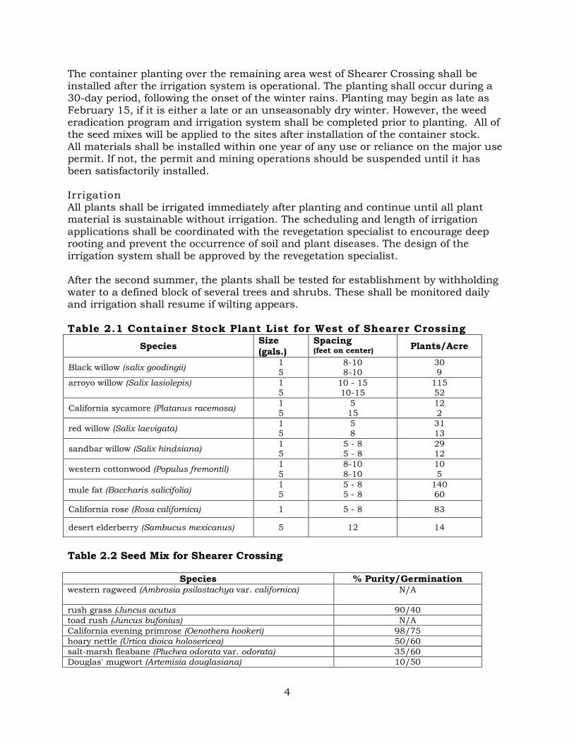
The container planting over the remaining area west of Shearer Crossing shall be installed after the irrigation system is operational. The planting shall occur during a 30-day period, following the onset of the winter rains. Planting may begin as late as February 15, if it is either a late or an unseasonably dry winter. However, the weed eradication program and irrigation system shall be completed prior to planting. All of the seed mixes will be applied to the sites after installation of the container stock. All materials shall be installed within one year of any use or reliance on the major use permit. If not, the permit and mining operations should be suspended until it has been satisfactorily installed. Irrigation All plants shall be irrigated immediately after planting and continue until all plant material is sustainable without irrigation. The scheduling and length of irrigation applications shall be coordinated with the revegetation specialist to encourage deep rooting and prevent the occurrence of soil and plant diseases. The design of the irrigation system shall be approved by the revegetation specialist. After the second summer, the plants shall be tested for establishment by withholding water to a defined block of several trees and shrubs. These shall be monitored daily and irrigation shall resume if wilting appears. Table 2.1 Container Stock Plant List for West of Shearer Crossing
Species Size (gals.)
Spacing (feet on center) Plants/Acre
Black willow (salix goodingii) 1 5
8-10 8-10
30 9
arroyo willow (Salix lasiolepis)
1 5
10 - 15 10-15
115 52
California sycamore (Platanus racemosa) 1 5
5 15
12 2
red willow (Salix laevigata) 1 5
5 8
31 13
sandbar willow (Salix hindsiana) 1 5
5 - 8 5 - 8
29 12
western cottonwood (Populus fremontil) 1 5
8-10 8-10
10 5
mule fat (Baccharis salicifolia) 1 5
5 - 8 5 - 8
140 60
California rose (Rosa californica) 1 5 - 8 83
desert elderberry (Sambucus mexicanus) 5 12 14
Table 2.2 Seed Mix for Shearer Crossing
Species % Purity/Germination western ragweed (Ambrosia psilostachya var. californica)
N/A
rush grass (Juncus acutus 90/40 toad rush (Juncus bufonius) N/A California evening primrose (Oenothera hookeri) 98/75 hoary nettle (Urtica dioica holosericea) 50/60 salt-marsh fleabane (Pluchea odorata var. odorata) 35/60 Douglas' mugwort (Artemisia douglasiana) 10/50

5
Table 2.3 Container Stock Plant List for Pala Road Realignment Slope Planting Species Size1 Spacing2 Plants/Acre Location3 sandbar willow (Salix hindsiana) 1 4 15 a,b,c red willow (Salix laevigata) 5 8 34 a,b,c,d arroyo willow (Salix lasiolepis) 5 8 83 a,b,c,d Black willow (salix goodingii) 5 8 77 a,b,c,d western cottonwood (Populus fremontil) 5 12 15 b,c,d Coast live oak (Quercus agrifolia) 5 20 19 e,f California sycamore (Platanus racemosa) 15 30 20 c,d toyon (heteromeles arbutiflia) 15 15 15 f desert elderberry (Sambucus mexicanus) 5 12 7 c,d,e mule fat (Baccharis salicifolia) 1 4 140 a,b California rose (Rosa californica) 1 4 21 e California blackberry ( California blackberry) 1 4 21 e 1 Size container measured in gallons. 2 Spacing measured in feet on center. 3 Planting locations along the Pala Road realignment slope (Figure 2.3):
a = streambed d = middle slope b = toe of channel e = upper slope c = lower slope f = top of bank
Table 2.4 Seed Mix for Pala Road Realignment Slope Planting Species %Purity/Germination Location flat-top buckwheat (Eriogonum fasdculalum) 10/65 e,f bush monkey flower (Diplacus puniceus) 2/55 e,f California sagebrush (A.rtemisia cali/ornica) 15/50 e,f mule fat (Baccharis salicifolia) 2/20 d western ragweed (Ambrosia psilostachya var. californica) N/A d,e 1Size container measured in gallons. 2 Planting locations along the Pala Road realignment slope (Figure 2.2):
a = streambed d = middle slope b = toe of channel e = upper slope c = lower slope f = top of bank
Table 2.5: Rosemary’s Mountain Quarry Seed Mix
Latin Name Common Name Lbs/Acre Min % Pur/Germ
Artemisia californica California sagebrush 7.0 15/50 Baccharis sarothroides Broom Baccharis 7.0 15/40 Mimulus aurantiacus San Diego monkeyflower 1.0 10/65 Eriogonum fasciculatum flat-top buckwheat 4.0 95/50 Dichelostemma capitatum Blue Dicks 3.0 90/60 Isomeris arborea Bladderpod 3.0 98/70 Penstemon spectabilis Showy Penstemon 1.0 95/75 Lotus scoparius deerweed 5.0 90/60 Lupinus bicolor Dove Lupine 5.0 98/70 Salvia apiana White Sage 5.0 70/50 Salvia columbariae Chia 5.0 90/60 Salvia mellifera Black Sage 5.0 70/50 Total 46

6
2.4 Site Protection The revegetation sites should be fenced to prevent vehicles and activities from the orchards from "spilling" into the revegetation area. The fencing should be based on open space boundaries located in the field by licensed surveyors. The fencing should be in place within two weeks following the installation of the container stock and consist of four-foot high chain link or split rail materials. The revegetation area west of Shearer Crossing will be" fenced only at the Shearer Crossing overpass. Fencing should not be needed around the remaining sides because they are inaccessible from the other directions. 2.5 Installation Maintenance and Monitoring The installation maintenance period begins on the first day after all revegetation installation on this project is complete, checked, accepted and written approval from the revegetation specialist is given to begin the maintenance period. This period shall continue for no less than 90 continuous calendar days. Regular maintenance shall begin immediately after the revegetation site is hydroseeded and planted. Plants and hydroseeded areas shall be kept in a healthy, growing condition and all areas shall be kept free of weeds, noxious grasses and other undesired vegetative growth. Weeding shall be conducted weekly. Plants found to be dead or in an impaired condition shall be replaced immediately. All work shall be conducted under the direction of the revegetation specialist. Monitoring will be qualitative only and will focus on survivorship and maintenance. Monitoring will be conducted daily during installation, weekly during the second month and biweekly thereafter for a total of four months (120 days). 3.0 FIVE-YEAR MAINTENANCE AND MONITORING PROGRAM 3.1 Purpose and Time Frame The need for maintenance of the revegetation area will be determined during the five-year monitoring program described in Section 4.2. The maintenance and monitoring program will be implemented for the revegetation site west of Shearer Crossing only. Repairs to the irrigation system, and other remedial actions to correct problems or damage resulting from natural causes, vandalism, or other reasons will be promptly performed on an as-needed basis. Quarterly monitoring reports (monthly during the first quarter) will identify additional maintenance needs. The quarterly reports will specifically address potential invasion by weedy species and identify corrective measures for their control. Required maintenance will be performed promptly, generally within two weeks of the identification of the problem. A monitoring program will be implemented to determine if the revegetation site is functioning as expected. The overall success of the mitigation program will be evaluated by comparing the final year of monitoring data with the target values. Monitoring will be conducted over a five-year period to identify trends and progress toward the target. Monitoring will also assess whether any adjustment to the original plan are needed. If the revegetation effort does not meet the success criteria, the project proponent shall continue with the replacement plantings, weed control, and

7
monitoring on a year-by-year basis until the criteria are met or three additional years, whichever occurs first. An annual report will be submitted to DPLU and CDFG each monitoring year that will cover plant monitoring as outlined below. 3.2 Monitoring Requirements Functions to be provided by the restored plant community include wildlife habitat, sustained biological diversity and structural diversity. The compensatory mitigation is expected to be established in five years. This created habitat is expected to continue to mature for a substantial period afterwards. The project proponent will be responsible for the implementation of this plan. This section describes the monitoring and reporting requirements to assist the project proponent in this effort and to evaluate the success of the mitigation and determine remedial actions where necessary. The five-year monitoring plan will begin after the installation monitoring period has been completed. A "time zero" report shall be prepared at the completion of plant installation, detailing the installation effort. This report shall be submitted to DPLU. The report shall provide actual "as-built" drawings for the revegetation areas. Plantings will be compared to the original planting plan with any deviation from the plan mapped and noted. Major deviations will be inspected by the revegetation specialist and, if necessary, additional plantings will occur to conform to the plan. The map of the site will identify planting methods, species, densities, and spacing of plants. An inspection shall be conducted with the revegetation specialist and the regulatory agency staff. The five-year monitoring period will start when the project is accepted by all parties. This report and the annual reports shall be submitted to the regulatory agencies for their review. The as-built drawings shall be approved by the revegetation specialist and DPLU staff. Monitoring will be conducted monthly for the first three months of the five-year plan, and quarterly thereafter for a total of 60 months (five years). The monthly monitoring surveys conducted during the first three months of the five-year plan will concentrate on qualitative observations to identify potential problems and recommend remedial actions, where necessary (i.e., plant die off, watering requirements and intrusion by unauthorized personnel). Remedial actions may include replacement of vegetation lost by disease, natural causes or other causes such that loss will jeopardize attainment of the criteria for success, as presented in Section 4.3. Replacement of vegetation should take place between October 1 and April 30. The quarterly monitoring surveys will collect both qualitative and quantitative data. Qualitative information will be similar to that collected during the first three months including identification of potential problems and remediation alternatives. Quantitative data will include analysis of survivorship and growth, including height and per cent cover of tree and shrub species. Survival will be measured by direct counts. Vegetation growth and establishment will be quantitatively assessed through the use of belt transects. There will be two belt transects per acre in each of the mitigation sites. In each transect, height will be determined for all container stock. Each container stock will be labeled with its scientific name (or abbreviation) and identification number. These data will be recorded on standard field data forms and I

8
along with notes of observations, kept on file by DPLU or their agent for documentation purposes. Data to be collected during quarterly monitoring surveys are described in Table 3.1. Photographs of the mitigation area will be taken from standard locations during each survey. Annual reports will be produced at the end of each monitoring year. These reports will be submitted to DPLU and the regulatory agencies for their review and evaluation. Each annual report will address the criteria for success, as detailed in Section 4.3 below, and measures needed to meet those criteria. Additionally, at the end of each monitoring year, a field meeti.ag will be held with the revegetation specialist and DPLU staff members to discuss the projects revegetation effort and success. Table 3.1 Data Collection Requirements for Mitigation Monitoring Monitoring Requirement Monitoring Method/Location Quarters Required
1 2 3 4
Quanitative Data Trees & Shrubs: Average and Range
Heights Calculate mean and standard deviation for planting types within transects
x x x x
Density Determine densities (mean and standard deviation) for planting types within transects
x x x x
Qualitative Data
Trees & Shrubs:
Aerial Cover Visually estimate percentage of cover for each planting type subarea
x x x x
Photos: From standard location x x x x 2.3 Criteria for Success In order to determine if the goals of the revegetation program have been achieved, certain success criteria must be met. Quantitative measures of these criteria include percentage survival of plantings and percent of coverage as indicated in Table 4. 1 and specifications described in this section and Section 4.4. Each monitoring report will evaluate if these criteria have been met and prescribe corrective measures if they have not. First-Year Monitoring. One year after planting, the first report shall be submitted to DPLU and CDFG. This report shall describe and delineate on large-scale maps, the revegetation sites. The standard for the first year shall be: Establishment of all species; 20 percent cover for groundcover plantings; and 80 percent healthy container plantings. The "Time Zero" report shall be included with this report.

9
The one-acre site planted with willow cuttings will be qualitatively evaluated for the number of willow cuttings that have successfully rooted. The revegetation specialist will determine if the container stock palette will need to be modified based upon the success rate of the willow cuttings. The container stock will be planted and seed mix hand broadcast over the one-acre site. Remedial Measures: If standards are not met, reseeding, replanting and possible substitution of plant material will be required. Second-Year Monitoring. At two years after planting, a second similar report shall be submitted to DPLU and CDFG for their review and comment. Records shall be kept of mortality and other problems, such as invasion of the revegetation site by exotic vegetation. Standards for the second year shall be: all trees and shrubs shall be of acceptable growth rate and height; 100 percent survival of all plantings; and 30 percent cover for groundcover plantings. Remedial Measures: Evaluate the cause of any stunted plants. Make necessary changes to rectify the problem. This may include replanting, soil amendments, regrading, etc. Third through Fifth-Year Monitoring. From the third through fifth years after planting, similar reports shall be submitted to the regulatory agencies listed above for their review and comment. Tree and shrub standards shall be 100 percent survival of all trees and shrubs; 75 percent cover for the third year; and 90 percent cover after year five. Remedial Measures: Replant if less than 100 percent survival rate for trees and shrubs. If less than 80 percent survival rate for groundcover, then additional seed or container plantings as recommended by the revegetation specialist shall be done. Each year, the success of the revegetation effort shall be evaluated by comparing factors such as density, spacing and height; and overall species composition with those of the control area See Section 4.4 for a description of the control area. The purpose of such analyses is to evaluate the rate and direction at which, the mitigation site is progressing as compared with the control area. It is important to view the growth of the revegetation area with the control area to account for uncontrollable factors such as fire or climate. If the revegetation does not meet the success criteria, the project proponent shall continue with the replacement plantings, weed control, and monitoring on a year-by-year basis until the criteria are met or three additional years, whichever occurs first. 2.4 Technical Measurements Field observations and measurements shall be recorded on a standard form to be developed and copies of these shall be submitted as an appendix to each report prepared for DPLU. Two belt transects per acre within each mitigation site would be established to measure plant heights. Permanent photo-documentation stations shall also be established within each mitigation site to visually document the vegetation changes and community development. Representative photographs shall be taken during each assessment. Each container planting within the belt transects shall be permanently marked to facilitate survivorship assessment. Aluminum tags or similar tags shall be used. This is important in order to determine planted natural succession

10
or integration during the monitoring period. A complete species list of all vascular plant species and vertebrate animal species encountered during the monitoring shall also be compiled. Measurements. Included in the "time zero" report shall be baseline measurements of a selected area of riparian habitat adjacent to the revegetation site. This survey shall be conducted to serve as statistical control. Height, density and spacing shall be measured within this control area. Following installation of container stock, the following data collection shall be implemented: Two belt transects per acre shall be randomly established and permanently located. Along the belt transects, the height, density and spacing shall be measured for each species. From this data, the average height along each transect and within the entire revegetation area will be determined for each species. Completed field data forms shall be submitted as an appendix to each required report. Within each transect the following data shall be collected:
a. Survivorship: assessed by absolute counts within the entire mitigation site. b. Plant height.

11
ATTACHMENT A
WEED ERADICATION SPECIFICATIONS
If extremely invasive and competitive weed species exist on-site they will out compete the native vegetation and shall therefore be eradicated prior to any installation of plant material. Seeds from these species can remain viable in the soil for many years. Therefore, a "grow and kill” weed eradication procedures may be necessary. If the areas proposed for revegetation are surrounded by existing stands of weeds (especially mustard), that will not be removed, re-infestation is likely to occur. To circumvent re-infestation a clean· "buffer zone" is recommended. Weeds adjacent to the revegetation area should be cut down regularly to remove seed stalks before the seeds ripen and re-disperse into the revegetation area. Caution should be used in areas where existing oak trees are located to avoid any watering and pesticides under the oaks. The "grow and kill" weed eradication program should include:
1. Clear and remove from site all existing weedy vegetation from the proposed revegetation areas as directed by the revegetation specialist.
2. Prepare soil surface as described above. 3. Install irrigation system. 4. Fertilize with 150 pounds per acre of 15-5-7 Turf Supreme with Best-Cote®. 5. Commence irrigating. The frequency and duration of irrigations will depend on
the time of year and the weather. The goal is to keep the soil surface (top 2-inch to 3-inch) moist but not wet. During the summer months, one to two irrigations per day should be sufficient. During other seasons adjust the irrigation schedule to maintain soil moisture.
6. Continue irrigating until a crop of weeds, I-inch to 3-inch in height becomes evident. During fall months this should occur rapidly, in 2 to 3 weeks, since this is the normal time for germination and growth of cool season weeds.
7. Discontinue irrigating and apply a broad spectrum herbicide (i.e., Round-up®) which will transfer to roots to kill the entire plant. The herbicide shall be recommended by a licensed pest control advisor.
8. Fertilize with 150 pounds per acre of 15-5-7 Turf Supreme with Best Cote®. 9. Recommence irrigating as described in steps #5 and #6 and spray herbicide per
step #7. 10. If after the second growing period dense weed infestation is still evident, then a
repeat of the "grow and kill" procedure is recommended. . 11. Once it has been determined that the weeds are under control then the planting
may be performed. The soil surface should be disturbed as little as possible as this will bring additional weed seeds to the surface.
12. Regular monitoring of the weed eradication procedures by the revegetation specialist is recommended so that adjustments to the timing of irrigation, herbicide spraying and seeding can be made.
13. No fertilizer should be applied as this may stimulate growth of additional weedy species. The native species can grow without applications of fertilizer.
14. The "grow and kill" procedures will not remove all weed seeds from the soil but can dramatically minimize the infestation. Regular hand weeding of the revegetation areas may be necessary until the native species are well established.

12
Many species of large invasive plants, such as giant reed and salt cedar, are difficult to eradicate using the "grow and kill" method. Any of these species that occur within the revegetation sites will be eradicated prior to revegetation. Eradication of both species is accomplished by cutting these species near ground level, and immediately, apply an approved herbicide for aquatic conditions. Removal must be conducted during the months of November through March when the plants are dormant or sap is flowing to the roots. In order for this method to be effective, the individual stems must be cut two to six inches from the ground and herbicide immediately applied to the entire cambium ring. The type of herbicide and timing of application will be directed by a licensed pest control advisor. A follow-up removal of missed or re-sprouted plants, using hand-clearing methods, will be conducted as part of the mitigation monitoring plan. Re-sprouted or missed plants shall be removed prior to the onset of flowering. Depending upon the effectiveness of the first treatment, the herbicide may need to be applied for two or three seasons to ensure the eradication of these persistent species.
Attachment B.
Storm Water Notice of Intent

State Water Resources Control Board
Linda S. Adams
Secretary for Environmental
Protection
Division of Water Quality 1001 I Street o Sacramento, California 95814 o (916) 341-5536
Mailing Address: P.O. Box 1977 o Sacramento, California o 95812-1977 FAX (916) 341-5543 o Internet Address: http://www.waterboards.ca.gov
Email Address:[email protected]
Arnold Schwarzenegger
Governor
Approved Date: 09/11/2007 Jayne Powell Granite Construction Co - Indio 38000 Monroe St Indio, CA 92203
RECEIPT OF YOUR NOTICE OF INTENT (NOI)
The State Water Resources Control Board (State Water Board) has received and processed your NOI to comply with the terms of the General Permit for Storm Water Discharges Associated with Industrial Activity. Accordingly, you are required to comply with the permit requirements. The Waste Discharger Identification (WDID) number is: 9 37I021142 . Please use this number in any future communications regarding this permit.
FACILITY DESCRIPTION
OPERATOR: Granite Construction Co - Indio FACILITY: Rosemarys Mountain Quarry
FACILITY LOCATION: SR76 E I15 Fallbrook, CA 92028
COUNTY: San Diego SIC/NAICS CODE(s): 1423 2951
When the operator changes (i.e. the business was bought or transferred), a new NOI, site map, and fee must be submitted by the new operator. As the previous operator, you are required to submit a Notice of Termination (NOT) to the local Regional Water Board stating you no longer own or operate the facility and covereage under the General Permit is not required. Unless notified, you will continue and are responsible to pay the annual fee invoiced each July. If you have any questions regarding permit requirements, please contact your Regional Water Board at (858) 467-2952. Please visit the storm water web page at www.waterboards.ca.gov/stormwtr/index.html to obtain an NOT and other storm water related information and forms. Sincerely, Storm Water Section Division of Water Quality
California Environmental Protection Agency

Attachment C.
Detention Basin Design

ChangCivil Engineering◦Hydrology◦Hydraulics◦Sedimentation
P.O. Box 9496 Rancho Santa Fe, CA 92067-4496
T: 858.692.0760 F: 858.832.1402
March 13, 2012 Dennis Fransway EnviroMINE, Inc. 3511 Camino del Rio South, Suite 403 San Diego, CA 92108 Subject: Rosemary’s Mountain Dear Dennis: Calculations have been prepared to size a desilting basin for the Rosemary’s Mountain project. The desilting basin will provide water quality treatment for sediment generated at the site. The calculation also considered self-retaining areas that do not require additional treatment controls. The calculations and associated materials are attached. There is a 24-inch overflow riser in the basin that connects to a 42-inch pipe, which has been sized for the 100-year flow. These facilities convey runoff out of the basin. Sincerely,
Wayne W. Chang, M.S., P.E. Enclosures

Summary The project is a mining site with the primary pollutant being sediment. As a result, the project proposes a concrete-lined desilting basin (i.e., extended/dry detention with impervious lining) at the downstream portion of the site. This basin will capture the on-site runoff before it is conveyed in a storm drain system under Pala Road to the San Luis Rey River, which is just south of the site. An extended/dry detention basin is identified in the County of San Diego SUSMP as an alternative treatment facility. The SUSMP requires that the basin volume be sized for the 85th percentile, 24-hour storm depth multiplied by the weighted runoff factor and tributary area. The portion of the 85th percentile rainfall map from the County of San Diego covering the site is attached and shows a rainfall depth of 0.83 inches. The weighted runoff factor and tributary area has been calculated for each project phase (Site Preparation, Phase 1, Phase 2, and Phase 3) based on the DMA exhibits in Attachment C. The calculations are included after this text and the results are summarized in Table 1. The proposed desiltation basin volume is 17,000 cubic feet, which is sufficient for all project phases.
Phase 85th Percentile,
24-hour Precip, in. Weighted Runoff
Factor Tributary Area, Ac
Required Detention Volume, cf
Site Preparation 0.83 0.35 9.84 10,305 1 0.83 0.27 20.19 16,635 2 0.83 0.32 11.26 10,732 3 0.83 0.51 3.61 5,520
Table 1. Desiltation Basin Sizing A series of self-retaining areas will be incorporated into the upper processing area pads and mined slope benches. The SUSMP requires that self-retaining areas be designed to retain the first one inch of rainfall without producing any runoff. The SUSMP indicates that areas can be bermed to retain the rainfall, so berms will be installed around the benches and pads to create retention (see the Source Control Exhibit for typical bermed self-retention areas). The rainfall volume is determined from the product of one inch of rainfall, weighted runoff factor, and tributary area. The calculations are included after this text and summarized in Table 2. The berms will provide storage in accordance with the tabulated values.
Phase Precipitation,
in. Weighted Runoff
Factor Tributary Area, Ac
Required Retention Volume, cf
Site Preparation 1.0 0.10 25.01 9,079 1 1.0 0.10 15.70 5,698 2 1.0 0.10 28.88 10,483 3 1.0 0.10 36.53 13,260
Table 2. Self-Retaining Area Sizing The Bio Clean Nutrient Separating Baffle Box was sized under the original plan approval.


DESILTATION BASIN ANALYSIS (see work maps for DMA Delineations)
SITE PREP PHASE
Lower Desiltation Basin (Extended Dry Detention Basin with Impervious Lining)
DMA Name Soil Type DMA Area, sf DMA Runoff Factor Area x Runoff Factor, sfImpervious A 20,803.35 1.0 20,803Pervious A 24,638.62 0.1 2,464
Impervious B 63,532.83 1.0 63,533Pervious B 229,838.39 0.1 22,984
Impervious D 33,565.54 1.0 33,566Pervious D 56,371.81 0.1 5,637
428,750.54 Total Tributary Area 0.35 Wtd. Avg. Runoff Factor
Volume = tributary area x weighted avg runoff factor x unit volume unit volume = 0.83" from 85th percentile map= 10,305 cubic feet
Upper Self-Retaining Areas
DMA Name Soil Type DMA Area, sf DMA Runoff Factor Area x Runoff Factor, sfPervious B 944,738.70 0.1 94,474Pervious D 144,699.40 0.1 14,470
1,089,438.10 Total Tributary Area 0.10 Wtd. Avg. Runoff Factor
Volume = tributary area x weighted avg runoff factor x unit volume unit volume = 1" for self-retaining area= 9,079 cubic feet
PHASE 1
Lower Desiltation Basin (Extended Dry Detention Basin with Impervious Lining)
DMA Name Soil Type DMA Area, sf DMA Runoff Factor Area x Runoff Factor, sfImpervious A 20,803.35 1.0 20,803Pervious A 24,638.62 0.1 2,464
Impervious B 109,112.82 1.0 109,113Pervious B 631,781.05 0.1 63,178
Impervious D 39,577.98 1.0 39,578Pervious D 53,681.22 0.1 5,368
879,595.04 Total Tributary Area 0.27 Wtd. Avg. Runoff Factor
Volume = tributary area x weighted avg runoff factor x unit volume unit volume = 0.83" from 85th percentile map= 16,635 cubic feet
Upper Self-Retaining Areas
DMA Name Soil Type DMA Area, sf DMA Runoff Factor Area x Runoff Factor, sfPervious B 537,031.47 0.1 53,703Pervious D 146,739.21 0.1 14,674
683,770.68 Total Tributary Area 0.10 Wtd. Avg. Runoff Factor
Volume = tributary area x weighted avg runoff factor x unit volume unit volume = 1" for self-retaining area= 5,698 cubic feet

PHASE 2
Lower Desiltation Basin (Extended Dry Detention Basin with Impervious Lining)
DMA Name Soil Type DMA Area, sf DMA Runoff Factor Area x Runoff Factor, sfImpervious A 20,803.35 1.0 20,803Pervious A 24,638.62 0.1 2,464
Impervious B 63,532.83 1.0 63,533Pervious B 253,210.65 0.1 25,321
Impervious D 33,565.54 1.0 33,566Pervious D 94,778.42 0.1 9,478
490,529.41 Total Tributary Area 0.32 Wtd. Avg. Runoff Factor
Volume = tributary area x weighted avg runoff factor x unit volume unit volume = 0.83" from 85th percentile map= 10,732 cubic feet
Upper Self-Retaining Areas
DMA Name Soil Type DMA Area, sf DMA Runoff Factor Area x Runoff Factor, sfPervious B 1,098,794.28 0.1 109,879Pervious D 159,121.89 0.1 15,912
1,257,916.17 Total Tributary Area 0.10 Wtd. Avg. Runoff Factor
Volume = tributary area x weighted avg runoff factor x unit volume unit volume = 1" for self-retaining area= 10,483 cubic feet
PHASE 3
Lower Desiltation Basin (Extended Dry Detention Basin with Impervious Lining)
DMA Name Soil Type DMA Area, sf DMA Runoff Factor Area x Runoff Factor, sfImpervious A 19,610.90 1.0 19,611Pervious A 24,638.62 0.1 2,464
Impervious B 26,665.74 1.0 26,666Pervious B 34,930.14 0.1 3,493
Impervious D 24,939.75 1.0 24,940Pervious D 26,345.02 0.1 2,635
157,130.17 Total Tributary Area 0.51 Wtd. Avg. Runoff Factor
Volume = tributary area x weighted avg runoff factor x unit volume unit volume = 0.83" from 85th percentile map= 5,520 cubic feet
Upper Self-Retaining Areas
DMA Name Soil Type DMA Area, sf DMA Runoff Factor Area x Runoff Factor, sfPervious A 1,107.53 0.1 111Pervious B 1,353,941.88 0.1 135,394Pervious D 236,181.09 0.1 23,618
1,591,230.50 Total Tributary Area 0.10 Wtd. Avg. Runoff Factor
Volume = tributary area x weighted avg runoff factor x unit volume unit volume = 1" for self-retaining area= 13,260 cubic feet

ATTACHMENT C
Drainage Management Area (DMA) Exhibit