ambient seismic noise tomography the banyumas basin
TRANSCRIPT

Page 1/27
Delineation of Sedimentary Basin Structure beneaththe Banyumas Basin, Central Java, Indonesia, UsingAmbient Seismic Noise TomographyAhmad Setiawan ( [email protected] )
Ministry of Energy and Mineral Resources: Kementerian Energi dan Sumber Daya Mineralhttps://orcid.org/0000-0001-6201-5249
Zulfakriza Zulfakriza ITB: Institut Teknologi Bandung
Andri Dian Nugraha ITB: Institut Teknologi Bandung
Shindy Rosalia ITB: Institut Teknologi Bandung
Awali Priyono ITB: Institut Teknologi Bandung
Sri Widiyantoro ITB: Institut Teknologi Bandung
David P. Sahara ITB: Institut Teknologi Bandung
Marjiyono Marjiyono Kementerian Energi dan Sumber Daya Mineral
Januar H. Setiawan ESDM: Kementerian Energi dan Sumber Daya Mineral
Eko Budi Lelono Kementerian Energi dan Sumber Daya Mineral
Asep K. Permana Kementerian Energi dan Sumber Daya Mineral
Hidayat Hidayat Kementerian Energi dan Sumber Daya Mineral
Research Article
Keywords: Banyumas sedimentary basin, volcanic area, hydrocarbon, Ambient Noise Tomography, cross-correlation, Green's Function, Rayleigh wave, shear wave.

Page 2/27
Posted Date: March 18th, 2021
DOI: https://doi.org/10.21203/rs.3.rs-314198/v1
License: This work is licensed under a Creative Commons Attribution 4.0 International License. Read Full License

Page 3/27
AbstractSubsurface images of an area with a thick volcanic layer generally can not be well-imaged withconventional seismic exploration (seismic re�ection) due to seismic wave scattering. Another method isneeded to obtain an accurate subsurface image in a thick volcanic layer area. In this study, we appliedAmbient Noise Tomography (ANT) to image the shear-wave velocity (Vs) structure in the BanyumasBasin, Central Java, Indonesia, which has relatively thick volcanic layers. We aimed to delineate thesediment deposits and the sedimentary thickness in this area. Although this method has limitedapplication for subsurface imaging with a thick volcanic layer area, the application of cross-correlationsfrom ambient noise has been widely applied in numerous locations to obtain greater understanding ofsubsurface structures. In this study, more than 1,000 pairs of vertical component cross-correlations wereused to estimate the Green's Function of the Rayleigh wave. The Multiple Filter Technique (MFT) wasused as a Time-Frequency Analysis and 1,291 dispersion curves were obtained. The NeighbourhoodAlgorithm (NA) was utilized to inverse the dispersion curves at 121 grid points which were used to obtaina vertical depth pro�le of 1D Vs. The Vs map results show that the low Vs tend to trend in a northwest-southeast direction associated with two areas: the Majenang low, and the Citanduy low. The presence oflow Vs values corresponds with Middle Miocene–Pliocene sedimentary rocks. Meanwhile, the high Vsvalue in this area might correspond with Oligocene–Early Miocene volcanic products and Eocenesediment. Our study was also able to reveal the thickness of sedimentary rocks in the the Banyumassedimentary basin, which is believed to have hydrocarbon potential.
1. IntroductionJava Island is located in the Indonesian archipelago and has unique geological features due to itssubducting plate zone. The existence of a recent volcanic arc on the island is a result of interactionsbetween the Eurasian and Indo-Australian Plates in the southern part of Java. The Indo-Australian Platemoves relatively north, perpendicular to Java Island since the Late Cretaceous era (Hall 2012), subductingbeneath the Eurasian Plate with a convergence rate of 67 mm yr-1 (Simon et al. 2007). This tectonicactivity has caused the development of faults and basins in the area, which are important for oil and gasplays.
Situmorang et al. (1976) suggest that the northward lateral compression force from the Indian oceanicplate and the southward lateral compression force from the Sundaland block present a wrench faulttectonism on Java Island, as �rst explained by Moody and Hill (1956). Due to these forces, pairs of strike-slip faults developed in opposite directions which meet in southern Central Java and caused thegeological settings in Central Java to become more complex than those of West and East Java (Satyana2007). These faults have also modi�ed the petroleum geology in Central Java, which generally developedin the forearc and backarc basins, as is present on Sumatra Island and on other parts of Java Island(Satyana 2007).
Page 4/27
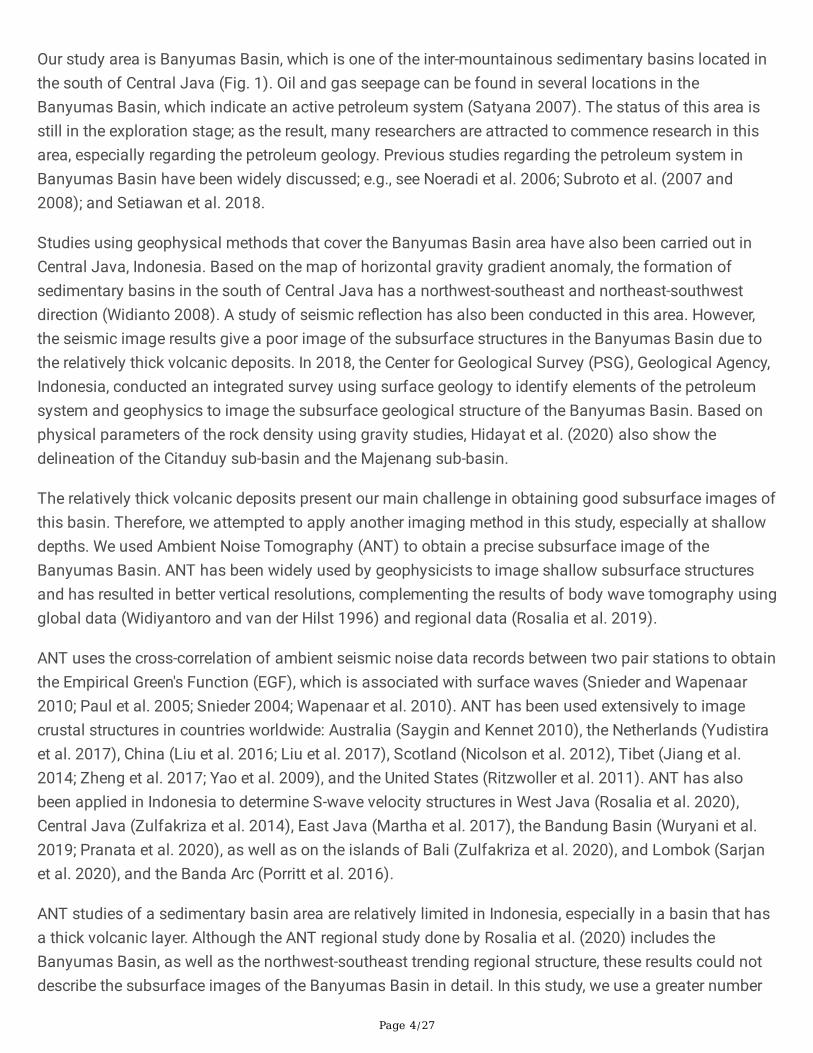
Our study area is Banyumas Basin, which is one of the inter-mountainous sedimentary basins located inthe south of Central Java (Fig. 1). Oil and gas seepage can be found in several locations in theBanyumas Basin, which indicate an active petroleum system (Satyana 2007). The status of this area isstill in the exploration stage; as the result, many researchers are attracted to commence research in thisarea, especially regarding the petroleum geology. Previous studies regarding the petroleum system inBanyumas Basin have been widely discussed; e.g., see Noeradi et al. 2006; Subroto et al. (2007 and2008); and Setiawan et al. 2018.
Studies using geophysical methods that cover the Banyumas Basin area have also been carried out inCentral Java, Indonesia. Based on the map of horizontal gravity gradient anomaly, the formation ofsedimentary basins in the south of Central Java has a northwest-southeast and northeast-southwestdirection (Widianto 2008). A study of seismic re�ection has also been conducted in this area. However,the seismic image results give a poor image of the subsurface structures in the Banyumas Basin due tothe relatively thick volcanic deposits. In 2018, the Center for Geological Survey (PSG), Geological Agency,Indonesia, conducted an integrated survey using surface geology to identify elements of the petroleumsystem and geophysics to image the subsurface geological structure of the Banyumas Basin. Based onphysical parameters of the rock density using gravity studies, Hidayat et al. (2020) also show thedelineation of the Citanduy sub-basin and the Majenang sub-basin.
The relatively thick volcanic deposits present our main challenge in obtaining good subsurface images ofthis basin. Therefore, we attempted to apply another imaging method in this study, especially at shallowdepths. We used Ambient Noise Tomography (ANT) to obtain a precise subsurface image of theBanyumas Basin. ANT has been widely used by geophysicists to image shallow subsurface structuresand has resulted in better vertical resolutions, complementing the results of body wave tomography usingglobal data (Widiyantoro and van der Hilst 1996) and regional data (Rosalia et al. 2019).
ANT uses the cross-correlation of ambient seismic noise data records between two pair stations to obtainthe Empirical Green's Function (EGF), which is associated with surface waves (Snieder and Wapenaar2010; Paul et al. 2005; Snieder 2004; Wapenaar et al. 2010). ANT has been used extensively to imagecrustal structures in countries worldwide: Australia (Saygin and Kennet 2010), the Netherlands (Yudistiraet al. 2017), China (Liu et al. 2016; Liu et al. 2017), Scotland (Nicolson et al. 2012), Tibet (Jiang et al.2014; Zheng et al. 2017; Yao et al. 2009), and the United States (Ritzwoller et al. 2011). ANT has alsobeen applied in Indonesia to determine S-wave velocity structures in West Java (Rosalia et al. 2020),Central Java (Zulfakriza et al. 2014), East Java (Martha et al. 2017), the Bandung Basin (Wuryani et al.2019; Pranata et al. 2020), as well as on the islands of Bali (Zulfakriza et al. 2020), and Lombok (Sarjanet al. 2020), and the Banda Arc (Porritt et al. 2016).
ANT studies of a sedimentary basin area are relatively limited in Indonesia, especially in a basin that hasa thick volcanic layer. Although the ANT regional study done by Rosalia et al. (2020) includes theBanyumas Basin, as well as the northwest-southeast trending regional structure, these results could notdescribe the subsurface images of the Banyumas Basin in detail. In this study, we use a greater number

Page 5/27
of local ambient seismic noise data sets recorded by 68 local stations with 60 days of observationbetween June and July 2018 to obtain more detail images in Banyumas basin. We aimed to delineate thesediment deposits which characterized by the low Vs pattern and present a vertical shear wave velocitystructure beneath the Banyumas Basin, as well as to determine the thickness of the sedimentary rocks inthe area. Our results are usefull in providing additional knowledge regarding the exploration challenges inthe Banyumas Basin.
2. Geological SettingsGeologically, the study area (Fig. 1) is predominantly covered with alluvial deposits and sedimentaryrocks from the Halang Formation. The sedimentary rocks of the Halang Formation consist of tuffaceoussandstones, conglomerates, marlies, clay stones, and andesitic breccias at the bottom level (Kastowo andSuwarna 1996). There are also volcaniclastic products from the Kumbang Formation of the same age asthat of the Halang Formation (Middle Miocene-Pliocene), which consist of volcanic breccias, lava, dykes,and tuffs composed of andesite and basalt. The Kumbang Formation connects with the HalangFormation and overlaps the Kalipucang Limestone (Middle Miocene). Above the sequential HalangFormation are several Pliocene formations, which consist of : the Kalibiuk Formation, which consists ofclay and marlite deposits; the Kaliglagah Formation, which consists of coarse sandstone andconglomerate deposits; and the Tapak Formation, which consist of coarse sandstone sediment with marlintercalations. Quarterly volcanic products and alluvium deposits can be found at the top of theseformations.
The older formation underneath the Halang Formation consists of the Rambatan Formation, the PemaliFormation (the term “Penanjung Formation” was �rst used by Setiawan (2019), the NusakambanganFormation, and the Jampang/Gabon Formation. The Rambatan Formation (Middle Miocene) consists ofsedimentary sandstone and conglomerate with marl and shale. The Pemali Formation (Middle Miocene)consists of sedimentary deposits of tuffaceous sandstones and sandy limestone. The NusakambanganFormation (Early Miocene) consists of tuff sediments with sandstone insertions. The Gabon Formation(Oligocene-Early Miocene) consists of breccia volcaniclastic deposits with pieces of andesite in atuff/sand matrix. The geological map of the survey area (Fig. 1) reveals that the Halang, Kumbang, andTapak Formations, as well as the alluvial deposits, tend to trend in a northwest-southeast direction.
3. Data And Method3.1 Data
In this study, waveform data from the seismic network deployed by the Center for Geological Survey(PSG), Geological Agency, Indonesia, was used. The seismic network used 68 portable 3-C broadbandborehole seismic stations in an area of less than 0.5 square degrees within the Banyumas Basin area,which is south of Central Java, Indonesia (Fig. 1). The data used was from the records of June and July2018. The minimum and maximum distances between the seismometer stations are 5 and 6 km,

Page 6/27
respectively. The waveform data was collected every two weeks; the batteries were replaced, and theseismometers checked in the same two-week timeframe. In this study, we utilized only those Rayleighwaves that were obtained from the cross-correlation results of the noise data between station pairs. As aresult, only the vertical component of the waveform data was used in the processing steps.
Several steps were �rst carried out before each seismometer was installed. First, a drillhole at the locationof the seismometer station was drilled; these averaged a depth of 16 meters. Secondly, the base of theborehole was cemented with mortar to make it easier to securely couple the seismometer. Thirdly, a 2.5inch diameter pipe was inserted into the drill hole. Fourthly, the seismometer was inserted into the drillhole. The last step was �lling the pipe with water to reduce noise from human activities.
To ensure safekeeping, the seismometers were located in the yards of selected residents, while therecording instruments were placed inside their houses. The seismic data was recorded and stored on a 16GB removable �ash disk (micro SD card). A real-time GPS was also connected to each recordinginstrument to record data in real-time. Another process that was also carried out was differential GPSmeasurements above the location of each of the seismometers to determine the location and height ofthe seismometer locations in greater detail.
3.2 Ambient noise cross-correlation and group velocity extraction
Ambient seismic noise interferometry refers to the process of cross-correlation between two sets ofambient seismic noise data that is recorded by two receivers in an acoustic diffusion wave�eld toproduce EGF at the receiver position as if one of the stations acts as the source (Wapeenar et al. 2006;Wapeenaar et al. 2010; Curtis 2006). Ambient seismic noise data recording has an advantage since itdoes not require earthquake sources, which means it can be measured at any time and anywhere (Curtis2006; Yang and Ritzwoller 2008). Yang and Ritzwoller (2008) also show that ambient noise sourcesgenerally take place over a short period (<20s) and are considered to be related to the interactionbetween ocean waves near the coastline and the ocean �oor. Generally, two maximum-sized peaks ofshort-term seismic noise were observed in the primary (10-20s) and secondary microseismic (5-10s) timeranges.
The procedure for preprocessing ambient seismic noise data follows Bensen et al. (2007), while the stepsused to produce the EGF of the Rayleigh wave follow those of Saygin and Kennet (2010), which were alsoused by Zulfakriza (2014 and 2020). The cross-correlation process between two stations, XA and XB, asstated by Saygin and Kennet (2010), could be written as:
Page 7/27
In this study, we produced 2,278 potential cross-correlation pairs from 68 broadband portable stations,using 60 days of continuous data, in order to determine the Vs velocity structure beneath the Banyumassedimentary basin. Because this study only used a vertical component of seismic data, Rayleigh waveswere the type of surface waves obtained from the cross-correlation process. We applied a narrowGaussian band to each EGF to determine the arrival time of the Rayleigh waves (Fig. 2A).
Surface waves have a unique dispersive characteristic that occurs when the velocity is a function ofperiod or frequency. We can measure the value of the surface wave velocity of different frequencies usinga dispersion curve. The EGF Rayleigh surface waves were obtained from the cross-correlation of datarecords between station pairs containing information about the velocity of the surface wave propagationin terms of frequency or time period. The Multiple Filtering Technique (MFT), introduced by Dziewonskieet al. (1969), was used to analyze the EGF and produce a Rayleigh surface wave dispersion curve for themedium between the station pairs. MFT is conducted by manually picking the maximum peak of theamplitude of the Rayleigh surface wave envelope. The dispersion curve obtained is then used for thetomographic inversion of the velocity of the Rayleigh wave group for each period.
From 2,278 potential EGF, we chose only those EGF that were clear enough to use in the dispersion curveanalysis. EGF that were too noisy were not used for further processing. We rejected more than 1,000 EGFand used only 1,291 EGF to produce a Rayleigh wave dispersion curve (Supplementary Fig. S1), whichwas done by manually picking the amplitude peak of the Rayleigh wave envelope in the fundamentalmode (Fig. 2B-C).
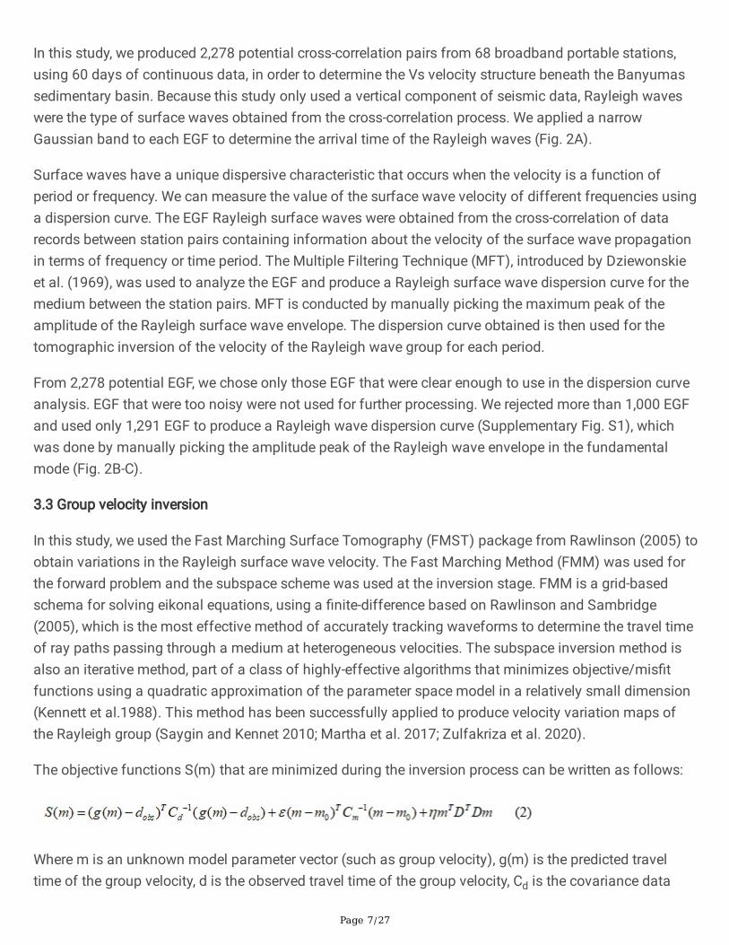
3.3 Group velocity inversion
In this study, we used the Fast Marching Surface Tomography (FMST) package from Rawlinson (2005) toobtain variations in the Rayleigh surface wave velocity. The Fast Marching Method (FMM) was used forthe forward problem and the subspace scheme was used at the inversion stage. FMM is a grid-basedschema for solving eikonal equations, using a �nite-difference based on Rawlinson and Sambridge(2005), which is the most effective method of accurately tracking waveforms to determine the travel timeof ray paths passing through a medium at heterogeneous velocities. The subspace inversion method isalso an iterative method, part of a class of highly-effective algorithms that minimizes objective/mis�tfunctions using a quadratic approximation of the parameter space model in a relatively small dimension(Kennett et al.1988). This method has been successfully applied to produce velocity variation maps ofthe Rayleigh group (Saygin and Kennet 2010; Martha et al. 2017; Zulfakriza et al. 2020).
The objective functions S(m) that are minimized during the inversion process can be written as follows:
Where m is an unknown model parameter vector (such as group velocity), g(m) is the predicted traveltime of the group velocity, d is the observed travel time of the group velocity, Cd is the covariance data

Page 8/27
matrix, m0 is the reference model, Cm is the model parameter covariance matrix, D is a smoothnessmatrix, e is a damping parameter, and h is a smoothing parameter.
3.4 Depth inversion
We applied the Neighbourhood Algorithm (NA) introduced by Sambridge (1999a, b) to determine thevariation of 1D shear wave velocity from the surface wave dispersion curve inversion. NA is a nonlinearinversion method classi�ed as a direct search method and is considered capable of solving inversionproblems that have quite complex relationships between observational data and unknown modelparameters. The NA direct search inversion method is divided into two stages. First, the search stage,which samples multi-dimensional parameter space to �nd a combination of model parameters that aresuitable for observational data. Second, the appraisal stage which extracts information from thecomplete ensemble of collected models to �nd a single optimal model. The search algorithm used by NAis in the same classi�cation as the GA and SA techniques; namely, randomly searching for the decisionfunction of the mis�t instead of using derivative calculations in the mis�t data function (free-derivativemis�t function).
Wathelet et al. (2008) successfully applied NA to produce new computer code for creating inversions ofRayleigh surface wave dispersion curves. The NA inversion algorithm was also used by Zulfakriza et al.(2020) to produce variations in velocity Vs to describe tomography beneath the Agung-Batur volcaniccomplex on Bali Island.
In this study, we used the Vp of checkshot velocity data obtained from measurements at the Jati-1 welllocation (Fig. 1) as the initial search model. The depth of the well from the recorded check shotinformation is approximately 4.3 km with a Vp value range from 2.5 km/s to 3.3 km/s. We obtained theVs value of the Jati-1 well by applying the empirical ratio of Vp/Vs 1.74 which was calculated from traveltime tomography data processing (Hidayat 2020). We also used a velocity model from CRUST 1.0 (Laskeet al. 2013) which is limited to the second layer and crystal crust 1 at a depth of 11.66 km. The minimumand maximum Vs values obtained from the CRUST 1.0 model are 0.88 km/s and 3.4 km/s, respectively.
4. Results4.1. Checkerboard resolution test
We used a Checkerboard Resolution Test (CRT) in a checkerboard pattern of low and high velocity groupsas an initial model to determine how well the study area could be recovered. We conducted severalcheckerboard cell sizes to test the proper resolution sizes as indicated by the checkerboard pattern'srecovery in this study. The optimum cell sizes were then applied to each period to obtain the tomographicimage of the velocity of the Rayleigh wave group.
We conducted three checkerboard resolution tests using different cell dimensions: ~8.5km x 8.5km, ~ 6.5km x 6.5km, and ~ 5.5km x 5.5km, as shown in Fig. 3. The three CRT experiments all used the same

Page 9/27
parameter. The results showed good recovery of the checkerboard pattern on the inside of the stationnetwork, compared to outside the station network. The checkerboard recovery results using a ~ 5.5km2
cell size show a smearing effect compared to the other cell sizes. Therefore, we decided to use the ~ 6.5km2 grid cell size as the optimum resolution size to be recovered in the study area. By using a ~ 6.5km2 grid cell size, we expected to image the study area's complex geological conditions in greaterdetail, as compared to previous studies.
Damping and smoothing parameters are important parameters for solving the optimum solution of theinversion of Eq. 1. We tested the damping parameter values of 10 − 5,000 and the smoothing parametervalues of 5 − 3,000 through the trade-off curve (Supplementary Fig. S2) and obtained an optimum valueof 300 and 300, respectively. The supplementary S3 image shows the results of the checkerboardresolution test at different periods, using a ~ 6.5km2 grid cell size, a damping parameter of 300, and asmoothing parameter of 300. The results show that the checkerboard recovery pattern is su�cient inperiods 1s to 6s. In contrast, in periods higher than 6s, the recovery pattern is insu�cient for indicating arecovery of the checkerboard pattern.4.2. Rayleigh wave group velocity maps
Tomographic inversion was performed on the observed travel time data extracted from the dispersioncurve to determine the variation in velocity of the Rayleigh wave group in periods 1 to 6s. Figure 4 showsthe distribution map of the velocity variation of the Rayleigh wave group in the study area in periods 1 to6s. The parameter used is the same as that was used in the optimum CRT. The map of the Rayleigh wavegroup velocity result in a high resolution velocity model inside the station network due to the largenumbers and the high density of the raypaths (shown in the inset map of Fig. 4). In this study, a longerperiod than 6s was not used because 6s already has a low resolution which relates to the reducedamount of ray path coverage (Supplementary Fig. S4).
The geological features of the group velocity map of the Rayleigh wave in Fig. 4 show the presence oftwo low group velocity values which are separated by high group velocity and have northwest-southeasttrending structures. The low group velocity might correspond to relatively thick sedimentary rocks in thearea which is evidenced by the distribution of alluvial sedimentary layer, the Halang, Kumbang, andTapak Formations and coincide with the depocenter of the Majenang Low (northwest) and the CitanduyLow (southeast). In addition to the high group velocity anomaly that separates the two low group velocity,other high group velocities are also present in the southwest and northeast.
4.3. Shear wave velocity modelWe successfully applied the NA algorithm, introduced by Sambridge (1999a, b), to produce a 2-D pro�leof shear wave velocity maps at each depth (Fig. 6). The Rayleigh wave dispersion curve obtained fromthe group velocity map for each period (1-6s) was then extracted to obtain a dispersion curve at 121points, which was evenly distributed at intervals of 0.05o (~ 5.5km) in the study area.

Page 10/27
The inversion of the 1D shear wave velocity (Vs) model was carried out on 121 grid point dispersioncurves that had previously been made using a dinver package, part of the Geopsy software developed byWathelet et al. (2008). The inversion results produced 1D Vs pro�les (Fig. 5). The results of the 1D Vspro�le produced velocity information (Vs) at different depths, dependent on the consistency of thedispersion curve at the selected grid points.
Several parameters need to be determined in the 1-D Vs inversion process; e.g., the total thickness modelfor the Earth's layer, the range of velocity of the search model, and the range of thickness of the Earth’slayer. In this study, we used �ve layers of parameters for the NA inversion process with different velocityvalues of Vs and depth thickness. The range of uniform Vs model parameters used for each layer were:500-1,300 m/s, 700-2,000 m/s, 1,000–2,300 m/s, 1,400-2,500 m/s, and 2,000–3,500 m/s. The modelparameters for the thickness of each layer were: 200-1,290 m (bottom depth), with the other three layersin the thickness range of: 1,290-1,500 m, 1,500-2,000 m, and 2,000–4,000 m.
Figure 5A-C shows three examples of the 1D Vs vertical pro�le obtained by applying the NeighborhoodAlgorithm. Figure 5D shows the location of three examples of 1D Vs. Figure 5A shows a gradual increasein the Vs values with increasing depth from the surface, as can be seen in the 1D Vs pro�le in Fig. 5B-C.After the inversion of the dispersion curve on all 121 grid points, we did an interpolation to obtain a 2D Vsmap at depths of 0.5-8 km (Fig. 6). The low Vs pattern that appears on the velocity map of the Rayleighwave group velocity is consistent with the map of Vs value distribution to a depth of 3 km (Fig. 6A-D) andtends to trend in the northwest-southeast direction; whereas higher Vs are dominant at depths of morethan 3 km.
5. DiscussionThe results of the 1-D pro�le inversion of Vs (Fig. 5) show a rock layer with an increasing velocitystructure; i.e., each Vs value is higher than in the previous layer. We show the 1-D pro�le inversion from 3different location in Fig. 5: in the northern part which characterized with high group velocity (Fig. 5A), andin the Majenang Low (Fig. 5B) and the Citanduy Low (Fig. 5C) which both characterized with low groupvelocity. The Vs value is reached at depth of 8,000 m in Fig. 5A, which is about 2,700 m/s, shallower thanthe Vs value that was achieved in Fig. 5B-C. This shows the possibility that rock layers with highervelocity structures can be found at shallower depths than in Fig. 5B-C. From Fig. 5, we also observed thatthere is a possibility that the response tendency of the low anomaly Vs extends to the middle of the studyarea.
Figure 5B-C is likely to be in a response area having the value of Vs in an area covered by Quaternarydeposits that trend northwest-southeast. Based on the response of the value of Vs produced at the samedepth of 8,000 m, Fig. 5B produces a Vs response value up to 2,500 m/s, while Fig. 6C produces aresponse value of Vs up to 2,200 m/s. This indicates the possibility of thicker sedimentary layers leadingsoutheast. In Fig. 5A-C, it also can be seen that the highest Vs value obtained starts at a depth of ~ 6,000m, along with the possibility of a rock structure discontinuity limit of the highest velocity value that can
Page 11/27
be found in the study area. We also note that the dispersion calculation curve in the fundamental modeof Fig. 5A-C is not very �t, following the change in velocity at 0.6-1 Hz frequencies. This indicates that thecomputational limitations in the frequency range are dependent on the grid size used. Since we used agrid size of ~ 6.5 km2, this indicates that a geological object sized less than ~ 6.5 km2 cannot be properlyresolved.
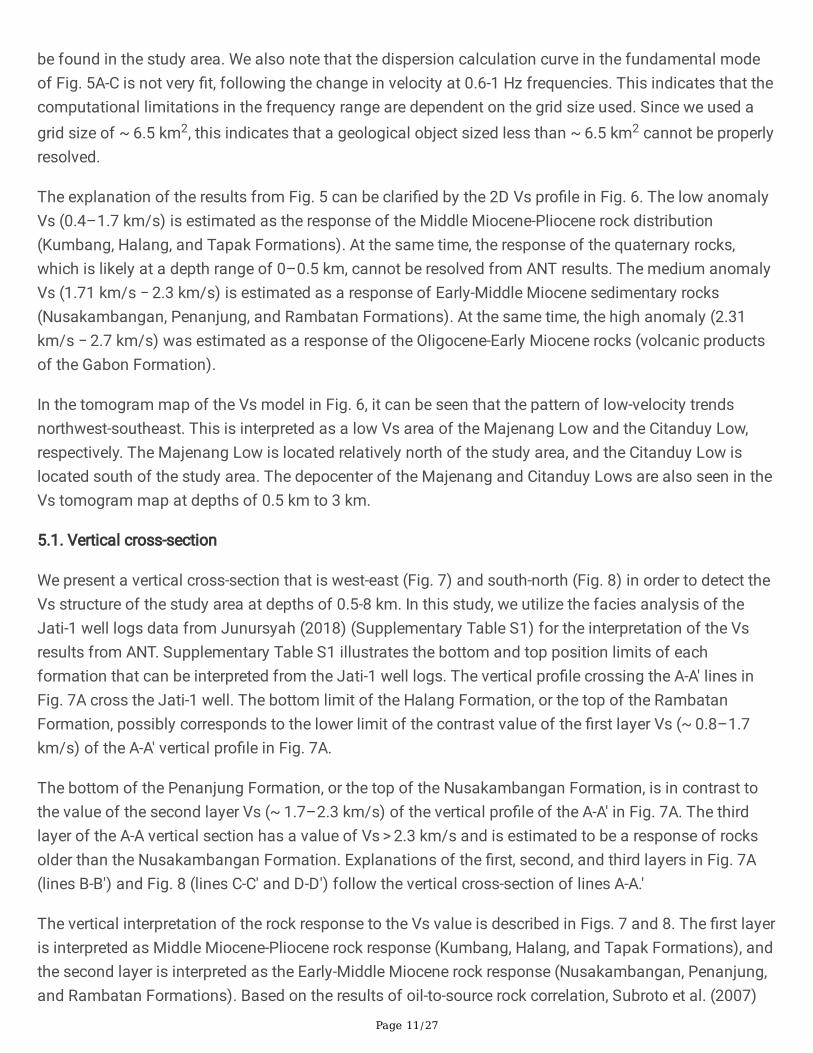
The explanation of the results from Fig. 5 can be clari�ed by the 2D Vs pro�le in Fig. 6. The low anomalyVs (0.4–1.7 km/s) is estimated as the response of the Middle Miocene-Pliocene rock distribution(Kumbang, Halang, and Tapak Formations). At the same time, the response of the quaternary rocks,which is likely at a depth range of 0–0.5 km, cannot be resolved from ANT results. The medium anomalyVs (1.71 km/s − 2.3 km/s) is estimated as a response of Early-Middle Miocene sedimentary rocks(Nusakambangan, Penanjung, and Rambatan Formations). At the same time, the high anomaly (2.31km/s − 2.7 km/s) was estimated as a response of the Oligocene-Early Miocene rocks (volcanic productsof the Gabon Formation).
In the tomogram map of the Vs model in Fig. 6, it can be seen that the pattern of low-velocity trendsnorthwest-southeast. This is interpreted as a low Vs area of the Majenang Low and the Citanduy Low,respectively. The Majenang Low is located relatively north of the study area, and the Citanduy Low islocated south of the study area. The depocenter of the Majenang and Citanduy Lows are also seen in theVs tomogram map at depths of 0.5 km to 3 km.
5.1. Vertical cross-section
We present a vertical cross-section that is west-east (Fig. 7) and south-north (Fig. 8) in order to detect theVs structure of the study area at depths of 0.5-8 km. In this study, we utilize the facies analysis of theJati-1 well logs data from Junursyah (2018) (Supplementary Table S1) for the interpretation of the Vsresults from ANT. Supplementary Table S1 illustrates the bottom and top position limits of eachformation that can be interpreted from the Jati-1 well logs. The vertical pro�le crossing the A-A' lines inFig. 7A cross the Jati-1 well. The bottom limit of the Halang Formation, or the top of the RambatanFormation, possibly corresponds to the lower limit of the contrast value of the �rst layer Vs (~ 0.8–1.7km/s) of the A-A' vertical pro�le in Fig. 7A.
The bottom of the Penanjung Formation, or the top of the Nusakambangan Formation, is in contrast tothe value of the second layer Vs (~ 1.7–2.3 km/s) of the vertical pro�le of the A-A' in Fig. 7A. The thirdlayer of the A-A vertical section has a value of Vs > 2.3 km/s and is estimated to be a response of rocksolder than the Nusakambangan Formation. Explanations of the �rst, second, and third layers in Fig. 7A(lines B-B') and Fig. 8 (lines C-C' and D-D') follow the vertical cross-section of lines A-A.'
The vertical interpretation of the rock response to the Vs value is described in Figs. 7 and 8. The �rst layeris interpreted as Middle Miocene-Pliocene rock response (Kumbang, Halang, and Tapak Formations), andthe second layer is interpreted as the Early-Middle Miocene rock response (Nusakambangan, Penanjung,and Rambatan Formations). Based on the results of oil-to-source rock correlation, Subroto et al. (2007)

Page 12/27
and Setiawan et al. (2018) estimate the existence of Eocene sediment which has potential as source rockin the Banyumas Basin, indicating the possible existence of further rock layers beneath the GabonFormation. The third layer of the A-A' vertical section is estimated to be the response of volcanic productsfrom the Gabon Formation (Oligocene–Early Miocene) and Eocene sediment. A very high contrast valueof Vs could not be obtained from our tomographic results, so it is possible that our tomographic resultsdo not cover the basement of the Banyumas Basin, which is older than the Eocene period.
Setiawan et al. (2018) state that the volcanic data obtained, namely the Gabon Formation, showstholeiitic a�nity and has a basaltic composition that is associated with an oceanic island/volcanic arc.At the same time, Christensen and Stanley (2003) show that the value of Vp and Vs for each type of rock;the results of their study also show the minimum Vp and Vs values for basaltic rocks, which is about 5.9km/s and 3.2 km/s. From these studies, we estimate that the results of ANT studies in the study areahave not yet reached the basement because the highest Vs value that can be achieved is still lower thanthe Vs value obtained by Christensen and Stanley (2003).
5.2. Comparison of ANT results with other methodsWe also compared ANT results with geophysical and geological methods, in addition to correlationsusing data facies analysis from the Jati-1 well logs (Fig. 7A), as seen in Fig. 9. From the results of the Vstomogram model (Fig. 9A), two patterns of low Vs anomaly in the study area were obtained; these arelocated in a relatively northwest-southeast direction and separated by the Cipari Anticline; namely, theMajenang Low and Citanduy Low. The depocenter of the Majenang Low is estimated to be northwest ofthe area, while the depocenter of the Citanduy Low is estimated to be southeast of the area. These aremarked by Vs anomaly values that are lower than the surrounding points. The pattern and direction of thelow Vs are relatively the same as the pattern of the low bouguer anomaly shown in Fig. 9B. The strike slipfaults southwest and northeast of the study area are interpreted as the Citanduy and the KarangbolongFaults. This interpretation is reinforced by Muchsin et al. (2002), as shown in Fig. 9C.
6. ConclusionsThe ambient noise cross-correlation technique was successfully applied to the vertical component dataof the seismic records carried out in the Banyumas sedimentary basin to produce the EFG of a Rayleighwave. The characteristic of the ambient noise source obtained in this area is in the secondarymicroseismic range (5s-10s period). ANT was able to delineate the subsurface structure of the BanyumasBasin, shown on the variations of Vs value at depths of 0.5 km to 8 km. Based on the map of variationsin the value of Vs, there are two low Vs value, which are interpreted as the Majenang Low and theCitanduy Low, respectively.
By utilizing the facies analysis of the Jati-1 well logs data from Junursyah (2018), we found three layersof subsurface structures in the Banyumas Basin that could be seen from the ANT results. The �rst layer,with a value of Vs 0.8 km/s − 1.7 km/s, is estimated to be a response from rocks of the Middle Miocene-Pliocene and consists of the Kumbang, Halang, and Tapak Formations. The second layer, with a value of
Page 13/27
Vs 1.71 km/s − 2.3 km/s, is estimated to be related to rocks of the Early-Middle Miocene and consists ofthe sediment of the Nusakambangan, Penanjung, and Rambatan Formations. The third layer, with a valueof Vs 2.31 km/s − 2.7 km/s, is estimated to consist of sedimentary rock of the Eocene and the EarlyOligocene-Miocene of Gabon Formation. Our �ndings could be used as additional information forhydrocarbon exploration in the Banyumas Basin.
DeclarationsAcknowledgements
We would like to thank Center for Geological Survey (PSG), Geological Agency, Indonesia for thewaveform data used in this study. Some of �gures presented were plotted using Generic Mapping Tools(Wessel and Smith 1998).
Availability of data and materials
Vs data will be shared through the PSG, Geological Agency, Indonesia website after this paper ispublished
Funding
This study was supported by the Ministry of Energy and Mineral Resources, Indonesia, for itsscholarship, the ITB Research Program 2019-2020, the Master's Thesis Research Program BP-PTNBHKemristek/BRIN 2020, and World Class Research Kemristek/BRIN Program 2021-2022 awarded to ADN.The study was also partially supported by and the Center for Earthquake Science and Technology,Research Center for Disaster Mitigation, Institut Teknologi Bandung (CEST, PPMB, ITB).
Authors' contributions
A.S., Z.Z., A.D.N., S.R., A.P., S.W., D.P.S. contributing to the data processing, interpretation, and writing ofthe manuscript. A.S., M.M., J.H.S., E.B.L., A.K.P., and H.H. conceived the seismic survey in Banyumasbasin area. All authors contributed to the preparation of the manuscript. All authors have read andapproved the �nal manuscript.
Competing Interests Statement
We declare that we have no signi�cant competing �nancial, professional or personal interests that mighthave in�uenced the performance or presentation of the work described in this manuscript.
ReferencesAsikin S, Handoyo A, Prastistho B, Gafoer S (1992) Peta Geologi Lembar Banyumas, Jawa, Skala1:100.000. Pusat Penelitian dan Pengembangan Geologi, Bandung

Page 14/27
Badan Geologi (2009) Peta Cekungan Sedimen Indonesia. Badan Geologi, Bandung
Bensen GD, Ritzwoller MH, Barmin MP, Levshin AL, Lin F, Moschetti MP, Shapiro NM, Yang Y (2007)Processing seismic ambient noise data to obtain reliable broad-band surface wave dispersionmeasurements. Geophys J Int 169:1239–1260. doi:10.1111/j.1365-246X.2007.03374.x
Christensen NI, Stanley D (2003) Seismic Velocities and Densities of Rocks. International Handbook ofEarthquake and Engineering Seismology 81B: 1587-1594
Curtis A, Gerstoft P, Sato H, Snieder R, Wapenaar K (2006) Seismic interferometry-turning noise intosignal. The leading edge, pp 1082-1092
Djuri M, Samodra H, Amin TC, Gafoer S (1996) Peta Geologi Lembar Purwokerto dan Tegal, Skala1:100.000. Pusat Penelitian dan Pengembangan Geologi, Bandung
Dziewonski AS, Bloch S, Landisman M (1969) A technique for the analysis of transient seismic signals.Bull Seismol Soc Am 59:427–444. doi:10.1016/j.ultras.2008.12.001
Hall R (2012) Late Jurassic–Cenozoic reconstructions of the Indonesian region and the Indian Ocean.Tectonophysics 570-571:1-41. doi:10.1016/j.tecto.2012.04.021
Hidayat H (2020) Delineasi Struktur Kecepatan Seismik 3-D pada Cekungan Banyumas, Jawa Tengah,Menggunakan Tomogra� Waktu Tempuh. Tesis Program Magister, Institut Teknologi Bandung
Hidayat H, Subagio S, Praromadani ZSA (2020) Interpretasi Struktur Geologi Bawah PermukaanBerdasarkan Updating Data Gaya Berat Cekungan Banyumas, Jawa Tengah. Jurnal Geologi danSumberdaya Mineral 21(3):111-118. doi:10.33332/jgsm.geologi.21.3.111-118p
Herrmann RB (2013) Computer programs in seismology. an evolving tool for instruction and research.Seismol Res Lett 84:1081-1088. doi:10.1785/0220110096
Jiang M, Ai Y, Zhou S, Chen YJ (2014) Distribution of the low velocity bulk in the middle-to-lower crust ofthe southern Tibet. implications for formation of the north-south trending rift zones. Earthq Sci 27(2):149-157. doi:10.1007/s11589-014-0080-1
Junursyah GML (2018) The Integration of Gravity, Magnetotelluric, Magnetic and Seismic Data inDelineating the Banyumas Basin, unpublished reports. Pusat Survei Geologi, Bandung
Kastowo, Suwarna N (1996) Peta Geologi Lembar Majenang, Jawa, Skala 1:100.000 Edisi ke-2. PusatPenelitian dan Pengembangan Geologi, Bandung
Kennett BLN, Sambridge MS, Williamson PR (1988) Subspace methods for large scale inverse problemsinvolving multiple parameter classes. Geophysical Journal 94: 237–247. doi: 10.1111/j.1365-246x.1988.tb05898.x
Page 15/27
Laske G, masters G, Ma Z, Pasyanos M (2013) Update on CRUST1.0 – A 1-degree global model of Earth'scrust. Geophysical Research Abstract 15: 2658
Liu C, Yao H (2017) Surface Wave Tomography with Spatially Varying Smoothing Based on ContinuousModel Regionalization. Pure Appl Geophys 174:937-953. doi: 10.1007/s00024-016-1434-5
Liu Z, Huang J, Yao H (2016) Anisotropic Rapyleigh wave tomography of Northeast China using ambientseismic noise. Physics of the Earth and Planetary Interiors 256:37-48. http.//dx.doi.org/10.1016/j.pepi.2016. 05.001
Martha AA, Cummins P, Saygin E, Widiyantoro S, Masturyono (2017) Imaging of upper crustal structurebeneath East Java-Bali, Indonesia with ambient noise tomography. Geoscience letters 4(14):1-12.doi:10.1186/ s40562-017-0080-9
Moody JD, Hill MJ (1956) Wrench fault tectonics. Geological Society of America. Bulletin 67:1207-1246
Muchsin N, Ryacudu R, Kunto TW, Budiyani S, Yulianto B, Wiyanto B, Nurjayadi A, Raharjo K, Riandra F(2002) Miocene hydrocarbon system of the Southern Central Java region. In: Proceeding of 31st AnnualConvention of Indonesian Association of Geologists
Nicolson H, Curtis A, Baptie B, Galetti E (2012) Seismic interferometry and ambient noise tomography inthe British Isles. Proceedings of the Geologists' Association 123:74-86. doi:10.1016/j.pgeola.2011.04.002
Noeradi D, Subroto EA, Wahono HE, Hermanto E, Zaim Y (2006) Basin evolution and hydrocarbonpotential of Majalengka-Bumiayu transpression basin, Java Island, Indonesia. In: AAPG InternationalConference and Exhibition, Perth, West Australia
Paul A, Campilo M, Margerin L, Larose E, Derode A (2005) Empirical synthesis of time-asymmetricalGreen functions from the correlation of coda waves. Journal of Geophysics Research 110:1-13. doi:10.1029/2004JB003521
Porritt RW, Miller MS, O’Driscoll LJ, Harris CW, Roosmawati N, da Costa LT (2016) Continent-arc Collisionin the Banda Arc imaged by ambient noise tomography. Earth and Planetary Science Letters 449:246-258.https://dx.doi.org/10.1016/j.epsl.2016.06.011
Pranata B, Yudistira T, Widiyantoro S, Brahmantyo B, Cummins PR, Saygin E, Zulfakriza Z, Rosalia S,Cipta A (2020) Shear wave velocity structure beneath Bandung basin, West Java, Indonesia from AmbientNoise Tomography. Geophysical Journal International 220(2):1045-1054. https://doi.org/10.1093/gji/ggz493
Rawlinson N, Sambridge M (2005) The fast marching method. an effective tool for tomographic imagingand tracking multiple phases in complex layered media. Exploration Geophysics 36: 341 – 350

Page 16/27
Rawlinson N (2005) FMST. Fast Marching Surface Tomography Package, Canberra . Research School ofEarth Science, Australian National University
Ritzwoller MH, Lin FC, Shen W (2011) Ambient noise tomography with a large seismic array. ComptesRendus Geoscience 343:558-570. doi:10.1016/j.crte.2011.03.007
Rosalia S, Widiyantoro S, Nugraha AD, Suspendi P (2019) Double-difference tomography of P- and S-wave velocity structure beneath the western part of Java, Indonesia. Earthquake Science 32:12-25. doi:10.29382/eqs-2019-0012-2
Rosalia S (2020) Crustal Structure Imaging Beneath Western Java Using Seismic Ambient NoiseTomography. Disertasi Program Doktor, Institut Teknologi Bandung
Sambridge M (1999a) Geophysical inversion with a neighborhood algorithm I. Searching a parameterspace. Geophys J Int 138:479–494. doi:10.1046/j.1365- 246x.1999.00876.x
Sambridge M (1999b) Geophysical inversion with a neighborhood algorithm II. Appraising the ensemble.Geophys J Int 138:727–746. doi:10.1046/j.1365- 246x.1999.00900.x
Sarjan AFN, Zulfakriza Z, Nugraha AD, Rosalia S, Wei S, Widiyantoro S, Cummins PR, Muzli M, Sahara DP,Puspito NT, Priyono A, A�f H (2020) Delineation of Upper Crustal Structure Beneath the Island of Lombok,Indonesia, Using Ambient Seismic Noise Tomography. Frontiers in Earth Science (Under Revision)
Satyana AH (2007) Central Java, Indonesia – A "Terra Incognita" in petroleum exploration: newconsideration on the tectonic evolution and petroleum implications. In: Proceedings of IndonesianPetroleum Association, Thirty-First Annual Convention and Exhibition
Saygin E, Kennett BLN (2010) Ambient seismic noise tomography of Australian continent.Tectonophysics 481:116 – 125. doi:10.1016/j.tecto. 2008.11.013
Setiawan R, Patriani EY, Yurnaldi D, Asmoro P, Sukapti S (2018) Stratigra� Cekungan Banyumas,unpublished reports. Pusat Survei Geologi, Badan Geologi, Bandung
Setiawan R (2019) Sistem hidrokarbon pada tatanan vulkanik. Konsep dan studi kasus. Publikasi khususeksplorasi hidrokarbon di sistem vulkanik. Pusat Survei Geologi, Badan Geologi, Bandung
Simandjuntak TO, Surono (1992) Peta Geologi Lembar Pangandaran, Jawa, Skala 1:100.000. PusatPenelitian dan Pengembangan Geologi, Bandung, Indonesia
Simons WJF, Socquet A, Vigny C, Ambrosius BAC, Abu SH, Promthong C, Subarya C, Sarsito DA,Mathussen S, Morgan P, Spakman W (2007) A decade of GPS in Southeast Asia: Resolving Sundalandmotion and boundaries. J Geophys Res 112:B06420. doi:10.1029/2005JB003868

Page 17/27
Situmorang B, Siswoyo, Thajib E, Paltrinieri F (1976) Wrench Fault Tectonics and Aspects of HydrocarbonAccumulation in Java. In: Proceedings of Indonesia Petroelum Association (IPA), Fifth AnnualConvention, pp 53-66
Snieder R (2004) Extracting the Green's function from the correlation of coda waves. A derivation basedon stasionary phase. Physical Review 69:1-18. doi:10.1103/PhysRevE.69.046610
Snieder R, Wapenaar K (2010) Imaging with ambient noise. Physic Today 63:44-49.doi:10.1063/1.3490500
Stein S, Wysession M (2003) An introduction to seismology, earthquake, and earth structure. BlackwellPublishing, Oxford, pp 86-101
Subroto EA, Noeradi D, Priyono A, Wahono HE, Hermanto E, Praptisih, Santoso K (2007) The paleogenebasin with the Kendeng Zone, Central Java island, and implications to hydocarbon prospectivity. In:Proceedings of Indonesian Petroleum Association, Thirty-�rst Annual Convention & Exhibition
Subroto EA, Ibrahim A, Hermanto E, Noeradi D (2008) Contribution of Paleogene and Neogene sedimentsto the petroleum system in the Banyumas sub-basin, southern Central Java, Indonesia. In: AAPGInternational Conference and Exhibition, Cape Town, South Africa, pp 1-6
Wapenaar K, Draganov D, Robertsson J (2006) Introduction to supplement on seismic interferometry.Geophysics 71(4):1-4
Wapenaar K, Draganov D, Snieder R, Campman X, Verdel A (2010) Tutorial on seismic interferometry. Part1 – Basic principles and applications. Geophysics 75(5):195-209. doi: 10.1190/1.3457445
Wathelet M, Jongmans D, Ohrnberger M, Bonnefoy-Claudet S (2008) Array performances for ambientvibrations on a shallow structure and consequences over Vs inversion. J Seismol 12:1–19. doi:10.1007/s10950-007- 9067- x
Widianto E (2008) Penentuan Kon�gurasi Struktur Batuan Dasar dan Jenis Cekungan dengan DataGayaberat serta Implikasinya pada Target Eksplorasi Minyak dan Gas Bumi di Pulau Jawa. DisertasiProgram Doktor, Institut Teknologi Bandung
Widiyantoro S, van der Hilst R (1996) Structure and evolution of the lithospheric slab beneath the SundaArc, Indonesia. Science 271:1566-1570
Wuryani SD, Yudistira T, Widiyantoro S (2019) Surface wave tomography using seismic ambient noisedata for subsurface imaging beneath Bandung basin, West Java and its surrounding. In: IOP ConferenceSeries. Earth and Environtmental Science
Yang Y, Ritzwoller MH (2008) Characteristics of ambient seismic noise as a source for surface wavetomography. Geochemistry Geophysics Geosystems 9(2):1-18. doi:10.1029/2007GC001814
Page 18/27
Yao H, Campman X, Hoop MV, Hilts RD (2009) Estimation of surface wave Green's functions fromcorrelation of direct waves, coda waves, and ambient noise in SE Tibet. Physics of the Earth andPlanetary Interiors 177:1-11. doi:10.1016/j.pepi.2009.07.002
Yudistira T, Paulssen H, Trampert J (2017) The crustal structure beneath The Netherlands derived fromambeint seismic noise. Tectonophysics 721:361-371. http./dx.doi.org/10.1016/j.tecto.2017.09.025
Zheng DC, Saygin E, Cummins P, Ge Z, Min Z, Cipta A, Yang R (2017) Transdimensional Bayesian seismicambient noise tomography across SE Tibet. Journal of Asian Earth Sciences 134:86-93.http.//dx.doi.org.10.1016.j.jseaes.2016.11.011
Zulfakriza Z, Saygin E, Cummins PR, Widiyantoro, S, Nugraha AD, Lühr BG, Bodin T (2014) Upper crustalstructure of central Java, Indonesia, from transdimensional seismic ambient noise tomography.Geophysical Journal International 197:630–635. doi:10.1093/gji/ ggu016
Zulfakriza Z, Nugraha AD, Widiyantoro S, Cummins PR, Sahara DP, Rosalia S, Priyono A, Kasbani K,Syahbana DK, Priambodo IC, Martanto M, Ardianto A, Husni YM, Lesmana A, Kusumawati D, Prabowo BS(2020) Tomography Imaging of the Agung-Batur Volcano Complex, Bali, Indonesia, From the AmbientSeismic Noise Field. Frontiers in Earth Science 8(43):1-11. doi:10.3389/feart.2020. 00043
Figures

Page 19/27
Figure 1
A Geological map of the study area (modi�ed from Simandjuntak and Surono 1992; Kastowo andSuwarna 1996; Djuri et al. 1996; Asikin et al. 1992) ; B Insert map of survey location. The yellow area isthe Banyumas Basin (Badan Geologi, 2009), the red square shows the survey location, and the redtriangle is a volcano on Java Island

Page 20/27
Figure 2
A Cross-correlogram between station pairs C33 against all possible receiving stations with an averageRayleigh wave velocity of 2.12 km/s. The position between station C33 and the other stations is indicatedon the inset map. The dashed blue line indicates the lagtime trend of the Rayleigh EGF waves as thedistance between stations increased. The blue wave signal indicates the result of cross-correlationbetween stations C33-C23, while the red wave signal indicates the result of cross-correlation betweenstations C33-C45; B-C The dispersion curve of the EGF picking process between stations C33-C23 andC33-C45. The white dot indicates the result of group velocity picked at the top of the envelope, with thered sphere denoting the maximum energy possessed by the Rayleigh wave

Page 21/27
Figure 3
A-C Synthetic Rayleigh wave group velocity models for each cell grid size, ranging between ~8.5 km x 8.5km, ~6.5km x 6.5km, and ~5.5 km x 5.5 km; and the �nal model obtained after applying the checkerboardresolution test for period 1s of the synthetic model, showing the distribution of stations in the study area.

Page 22/27
Figure 4
A-F The Rayleigh wave group velocity map at periods 1 to 6s and the raypath shown in the insert map.The low group velocity, high group velocity and the developing structures in this area tend to trendnorthwest-southeast

Page 23/27
Figure 5
A-C Three examples of dispersion curve inversions at three different locations; D Coordinates of threeexamples (denoted by blue dots) of the application of dispersion curve inversion in the study area. Small,gray dots denote the 121 grid points of the dispersion curve inversion

Page 24/27
Figure 6
Shear wave velocity (Vs) maps at various depths, (A) 0.5 km, (B) 1 km, (C) 2 km, (D) 3 km, (E) 5 km, and(F) 8 km.

Page 25/27
Figure 7
A Vertical cross-section of Vs structure for lines A-A' and B-B' at longitudes 107.776o and 108.85o; BPosition of lines A-A' and B-B' on the map is denoted by black lines, the red dashed lines are the limits ofthe ANT tomographic resolution, and the red dot is the location of the Jati-1 well.
Figure 8
A Vertical cross-section of Vs structure for lines C-C' at latitude -7.4o and lines D-D' at latitude -7.6o; BPosition of lines C-C' and D-D' are shown on the map by a black line black; the red dashed line is the

Page 26/27
boundary resolution of ANT tomography, and the red dot is the location of the Jati-1 well
Figure 9
Comparison of results of the ANT in this study with gravity and geological studies. A Tomogram model ofVs at a depth of 2 km and interpretation of the structure and delineation. The area within the dashedblack lines represents the resolution limit of the ANT method. The two dashed red lines of low Vs indicatethe Majenang Low and the Citanduy Low, separated by the Cipari Anticline. The Citanduy Fault locatedSW and the Karangbolong Fault located NE, according to Fig. 9C; B The residual bouguer anomaly map(modi�ed from Hidayat et al. 2020); the dashed red line depicted in Fig. 9A shows low Vs delineation; C

Page 27/27
Con�guration of Miocene structure in the southern Central Java (modi�ed from Muchsin et al. 2002). Theblack square is the study area, utilizing ANT
Figure 10
A The vertical section of Vs structure passing through Jati-1 well in the seismic cross-section (E-E’); B Vsstructure at a depth of 0.5 km. Blue and red color indictes high and low value of Vs.
Supplementary Files
This is a list of supplementary �les associated with this preprint. Click to download.
supplementarymaterialANTBanyumasIndonesia.docx