amazon manual, revd
TRANSCRIPT
AMAZON BUBBLER
OWNERS MANUALREV. D
Item#361756REFD84-06 0816
Amazon Bubbler Shown With Optional Display
This user manual is a guide for the Amazon Bubbler. For more information, updated manuals, brochures, technical notes, and supporting software on the Amazon Bubbler, please refer to ysi.com/Amazon or contact your sales representative.
For additional assistance, please contact us at +1.435.753.2212 or [email protected]
CONTENTS & WARRANTY
Warranty.........................................................................1Chapter 1: Introduction...............................................2
3Chapter 2: Getting Started.........................................5
679999
10111112
Chapter 3: Installation...............................................131414141515
Chapter 4: Setup & Operation - Software............161717171717202326262729293133
Chapter 5: Setup & Operation - Keypad..............34353535363637
Bubbler Features........................................................ What’s in the Box.........................................................Product Description.................................................... Initial Testing.................................................. Power-up........................................................Communicate.............................................................. Using the Amazon with Display..................Using the Amazon Web Interface........................... USB Wi-Fi Connection................................ USB Cable Connection............................... Amazon Graphical User Interface.............
Water Depth..............................................................Mounting...................................................................Desiccator..................................................................Orifice Line................................................................Power Wiring.............................................................
Software Interface.................................................... Navigation Pane......................................... Current Screen Content............................ Site ID, Connection, and Status................ Home Page................................................. Bubbler....................................................... Data............................................................. SDI-12.......................................................... 4-20 mA....................................................... Modbus....................................................... Cell Modem................................................ Storm Central............................................. System Setup............................................. Ethernet......................................................
Keypad - Display........................................................ Home Screen................................................ Main Menu................................................... Sub Menu Editable Fields.......................... Level Sensor Menu...................................... Bubbler menu..............................................
384042434445
Chapter 6: SDI-12 Interface.....................................50505051525353545556
565757585959
Chapter 7: Modbus Operation................................6061616165
Chapter 8: Appendix.................................................67687072
Logging / Data Menu.................................. System Setup Menu..................................... SDI-12 Menu................................................. 4-20 mA Menu.............................................. Modbus Menu.............................................. Ethernet menu..............................................
Default Setup................................................ SDI-12 Address............................................ Level Units / Slope...................................... Set Current Level......................................... Level Offset................................................... Level Averaging Time.................................. Bubble Rate.................................................. Purge............................................................. Purge Pressure............................................. Purge Sustain............................................... 4-20 Milliamp Output................................. 4-20 Milliamp Min Level............................. 4-20 Milliamp Max Level............................. Modbus Mode Enable................................Help.............................................................................
Modbus....................................................................... Communication Setup................................ Function Codes............................................ Modbus Command Examples...................
Appendix A:Orifice Line Installation.......................Appendix B: Error Codes.........................................Appendix C: Specifications......................................
1
Contents & Warranty
“PRODUCTS MANUFACTURED BY YELLOW SPRINGS INSTRUMENTS CO., INC. are warranted by Yellow Springs Instruments Co., Inc. (“YSI”) to be free from defects in materials and workmanship under normal use and service for twenty four (24) months from date of shipment unless otherwise specified in the corresponding YSI pricelist or product manual.
Products not manufactured, but that are re-sold by YSI, are warranted only to the limits extended by the original manufacturer. Batteries, desiccant, and other consumables have no warranty. YSI’s obligation under this warranty is limited to repairing or replacing (YSI’s option) defective products, which shall be the sole and exclusive remedy under this warranty.
The customer shall assume all costs of removing, reinstalling, and shipping defective products to YSI. YSI will return such products by surface carrier prepaid within the continental United States of America. To all other locations, YSI will return such products best way CIP (Port of Entry) INCOTERM® 2010, prepaid. This warranty shall not apply to any products which have been subjected to modification, misuse, neglect, improper service, accidents of nature, or shipping damage. This warranty is in lieu of all other warranties, expressed or implied. The warranty for installation services performed by YSI such as programming to customer specifications, electrical connections to products manufactured by YSI, and product specific training, is part of YSI’s product warranty. YSI EXPRESSLY DISCLAIMS AND EXCLUDES ANY IMPLIED WARRANTIES OF MERCHANTABILITY OR FITNESS FOR A PARTICULAR PURPOSE. YSI is not liable for any special, indirect, incidental, and/or consequential damages.”
A complete TERMS AND CONDITIONS OF SALE can be viewed at:http://www.ysi.com/terms-and-conditions.php
Logging / Data Menu.................................. System Setup Menu..................................... SDI-12 Menu................................................. 4-20 mA Menu.............................................. Modbus Menu.............................................. Ethernet menu..............................................
Default Setup................................................ SDI-12 Address............................................ Level Units / Slope...................................... Set Current Level......................................... Level Offset................................................... Level Averaging Time.................................. Bubble Rate.................................................. Purge............................................................. Purge Pressure............................................. Purge Sustain............................................... 4-20 Milliamp Output................................. 4-20 Milliamp Min Level............................. 4-20 Milliamp Max Level............................. Modbus Mode Enable................................Help.............................................................................
Modbus....................................................................... Communication Setup................................ Function Codes............................................ Modbus Command Examples...................
Appendix A:Orifice Line Installation.......................Appendix B: Error Codes.........................................Appendix C: Specifications......................................
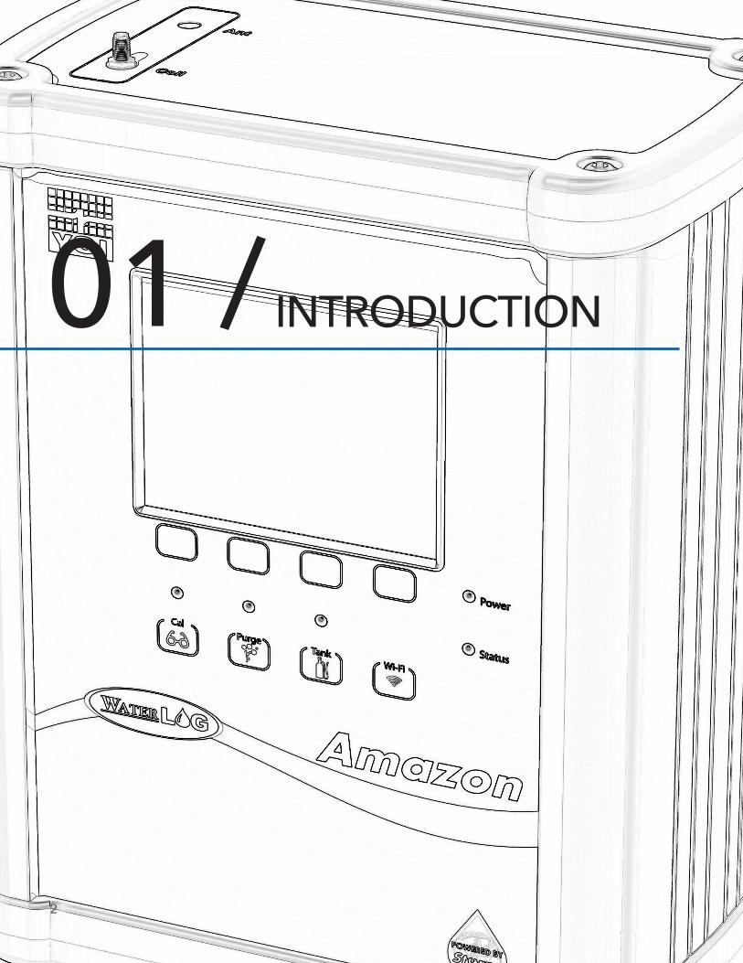
INTRODUCTION01 /
2
Ch1: Introduction
3
The Amazon is a “Powered by Storm” bubbler system. Like its H-3553T predecessor, the Amazon is a “compact-combo” system because of its small size and built in calibrated pressure sensor with the bubbler system. Designed to produce a precision constant mass flow of gas, the Amazon system is used to measure fluid levels in applications such as surface water (streams and lakes, etc.), ground water and tanks.
“Powered by Storm” means that the bubbler provides that same key functionality of the Storm 3 data loggers. These include:
• Wi-Fi connectivity to smart phones, tablets, and computers. • Direct connectivity to our Storm Central Data Hosting solutions via Ethernet.• Simple user configuration with browser based software.
The Amazon is a stand-alone system that can record data and push this data to the Storm Central Data Hosting, as well as to be used as a sensor connected with any data logger, PLC, RTU, or Data Collection Platform (DCP). It works seamlessly with any SDI-12 recorder device.
The Amazon bubbler system uses a battery operated compressor to maintain pressure in an internal tank. A microprocessor determines how much pressure is needed in the tank, based on the current head pressure, to produce a constant bubble rate. The compressor and tank replace the dry nitrogen tank used in previous systems.
A sophisticated system of sensors and valves regulate the bubble rate and purge pressure. This portion of the Amazon replaces the sight feed flow controller and pressure regulator (Conoflow system) used in previous systems.
The Amazon bubbler system also provides a purge feature which temporarily pumps up the tank to a high pressure and opens a valve to apply high pressure to the orifice line. This feature is designed to remove any sediment that may have collected in or around the outlet of the orifice line.
Key Features:
• Easy to use standalone web browser menu setup• Connection to web browser via Wi-Fi wireless connection, USB port, or RJ-45 • Built in calibrated pressure sensor• RS-485 MODBUS Client/Slave device (available in V1.2 or later)• Auto update mode, measures itself based on user defined rate• SDI-12 interface, 4 – 20mA output, and RS-485 MODBUS data output
Keypad Features:
• ‘Update’ button causes the Amazon to initiate a new measurement• ‘Purge’ button causes the Amazon to initiate a line purge• ‘Tank’ button causes the Amazon to release the pressure from the tank• ‘Cal’ button causes the Amazon to verify the sensor. • Optional continuous display readout always shows last measured value• Optional continuous display menu provides complete system configuration and data retrieval
Features: • Provides a continuous gas flow• Battery operated – Low power• Microprocessor controlled, “smart” gas system• One-piece manifold eliminates many potential sources of leaks• Digital pressure gauge provides a visual indication of the tank pressure• Hydrophobic intake membrane, protects compressor• Piston type compressor does not have a “diaphragm”• Provides an internal pressure relief valve• The Amazon is designed and rated for extreme temperature (-40 ° to +60 ° C) operation• Controlled and monitored as an SDI-12 sensor
CH1: INTRODUCTION
4
5
GETTING STARTED02 /
CH2: GETTING STARTED
6
What’s In The Box?
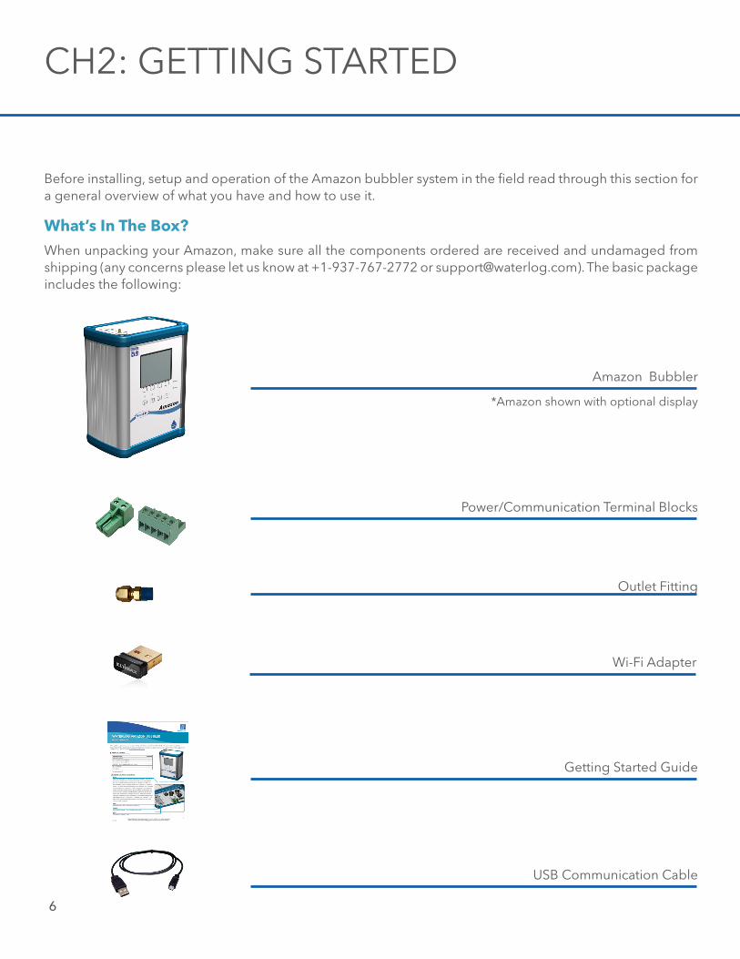
Before installing, setup and operation of the Amazon bubbler system in the field read through this section for a general overview of what you have and how to use it.
When unpacking your Amazon, make sure all the components ordered are received and undamaged from shipping (any concerns please let us know at +1-937-767-2772 or [email protected]). The basic package includes the following:
Amazon Bubbler
Power/Communication Terminal Blocks
Outlet Fitting
Wi-Fi Adapter
*Amazon shown with optional display
Getting Started Guide
USB Communication Cable
Ch2: Getting Started
7
Common Optional Items:
• H-355-DES - Desiccating Air Dryer• H-355-INS - Orifice Installation Kit• H-355-OL - Orifice Line (1000 ft minimum)• H-355-DP - Replacement Air Dryer Desiccant• H-SDI-CABLE - 4-Conductor SDI-12 Communication Cable
Please verify you have received these components and any other optional equipment you may have ordered.
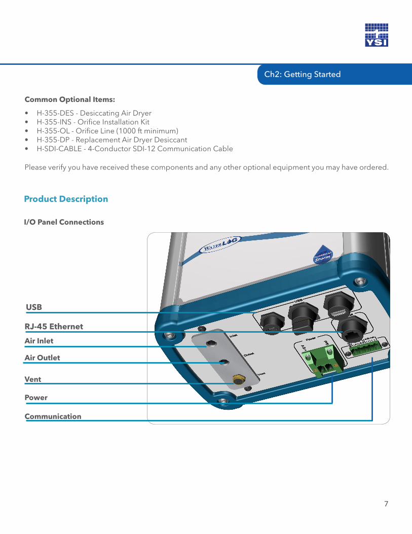
Product Description
I/O Panel Connections
Air Inlet
Air Outlet
Vent
RJ-45 Ethernet
Power Communication
USB
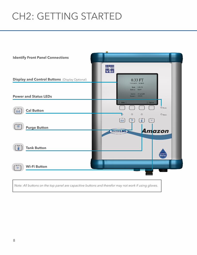
Identify Front Panel Connections
Cal Button
Purge Button
Tank Button
Wi-Fi Button
Display and Control Buttons (Display Optional)
CH2: GETTING STARTED
8
Note: All buttons on the top panel are capacitive buttons and therefor may not work if using gloves.
Power and Status LEDs
Ch2: Getting Started
9
Initial Testing
Before installing the Amazon bubbler system in the field, it is a good practice to test the system in the shop or lab. This will help preparations for a successful field install.
Power Up
Follow these steps to power up the Amazon:
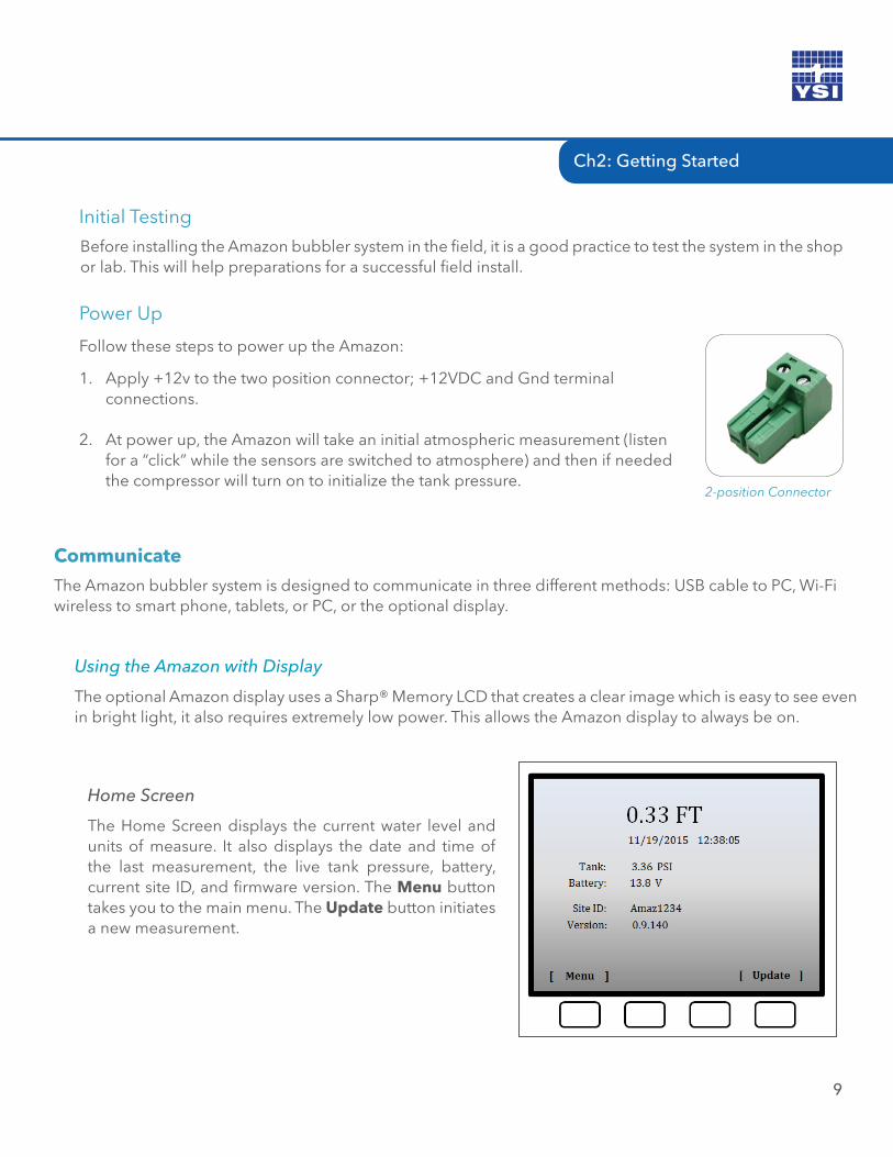
1. Apply +12v to the two position connector; +12VDC and Gnd terminal connections.
2. At power up, the Amazon will take an initial atmospheric measurement (listen for a “click” while the sensors are switched to atmosphere) and then if needed the compressor will turn on to initialize the tank pressure.
CommunicateThe Amazon bubbler system is designed to communicate in three different methods: USB cable to PC, Wi-Fi wireless to smart phone, tablets, or PC, or the optional display.
Using the Amazon with Display
The optional Amazon display uses a Sharp® Memory LCD that creates a clear image which is easy to see even in bright light, it also requires extremely low power. This allows the Amazon display to always be on.
Home Screen
The Home Screen displays the current water level and units of measure. It also displays the date and time of the last measurement, the live tank pressure, battery, current site ID, and firmware version. The Menu button takes you to the main menu. The Update button initiates a new measurement.
2-position Connector
CH2: GETTING STARTED
10
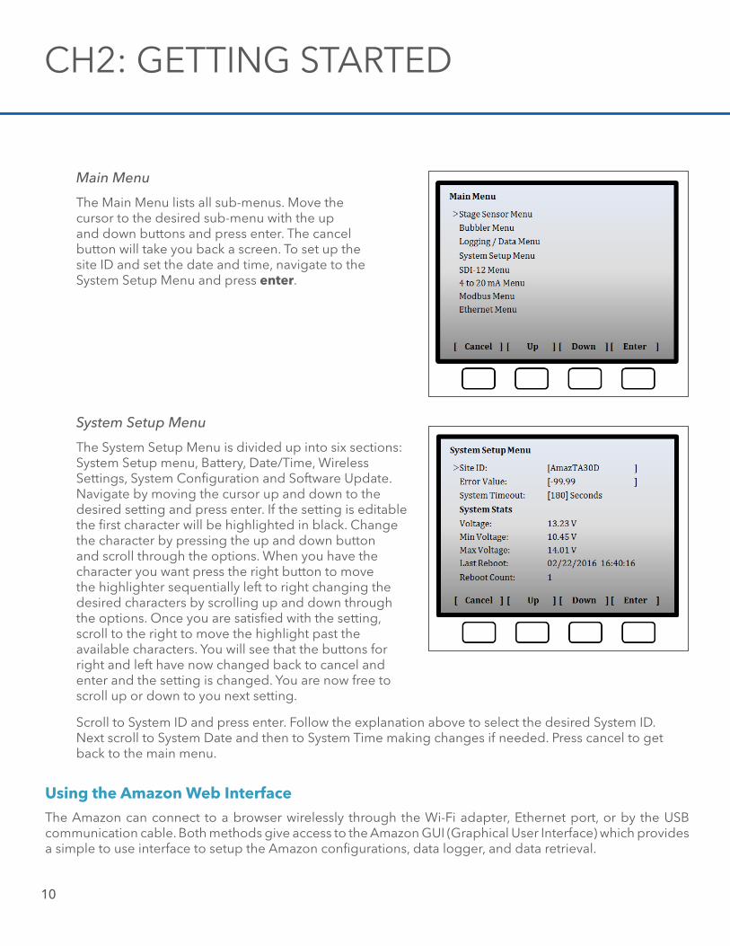
System Setup Menu
The System Setup Menu is divided up into six sections: System Setup menu, Battery, Date/Time, Wireless Settings, System Configuration and Software Update. Navigate by moving the cursor up and down to the desired setting and press enter. If the setting is editable the first character will be highlighted in black. Change the character by pressing the up and down button and scroll through the options. When you have the character you want press the right button to movethe highlighter sequentially left to right changing the desired characters by scrolling up and down through the options. Once you are satisfied with the setting, scroll to the right to move the highlight past the available characters. You will see that the buttons for right and left have now changed back to cancel and enter and the setting is changed. You are now free to scroll up or down to you next setting.
Using the Amazon Web InterfaceThe Amazon can connect to a browser wirelessly through the Wi-Fi adapter, Ethernet port, or by the USB communication cable. Both methods give access to the Amazon GUI (Graphical User Interface) which provides a simple to use interface to setup the Amazon configurations, data logger, and data retrieval.
Main Menu
The Main Menu lists all sub-menus. Move the cursor to the desired sub-menu with the upand down buttons and press enter. The cancelbutton will take you back a screen. To set up the site ID and set the date and time, navigate to the System Setup Menu and press enter.
Scroll to System ID and press enter. Follow the explanation above to select the desired System ID. Next scroll to System Date and then to System Time making changes if needed. Press cancel to get back to the main menu.
Ch2: Getting Started
11
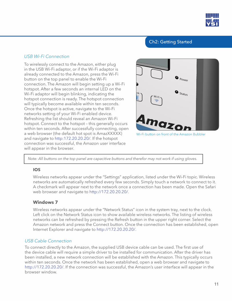
USB Wi-Fi Connection
To wirelessly connect to the Amazon, either plug in the USB Wi-Fi adaptor, or if the Wi-Fi adaptor is already connected to the Amazon, press the Wi-Fi button on the top panel to enable the Wi-Fi connection. The Amazon will begin setting up a Wi-Fi hotspot. After a few seconds an internal LED on theWi-Fi adaptor will begin blinking, indicating the hotspot connection is ready. The hotspot connectionwill typically become available within ten seconds.Once the hotspot is active, navigate to the Wi-Finetworks setting of your Wi-Fi enabled device. Refreshing the list should reveal an Amazon Wi-Fi hotspot. Connect to the hotspot – this generally occurs within ten seconds. After successfully connecting, open a web browser (the default hot spot is AmazXXXXX)and navigate to http:172.20.20.20/. If the hotspot connection was successful, the Amazon user interface will appear in the browser.
Note: All buttons on the top panel are capacitive buttons and therefor may not work if using gloves.
IOS
Wireless networks appear under the “Settings” application, listed under the Wi-Fi topic. Wireless networks are automatically refreshed every few seconds. Simply touch a network to connect to it. A checkmark will appear next to the network once a connection has been made. Open the Safari web browser and navigate to http://172.20.20.20/.
Windows 7
Wireless networks appear under the “Network Status” icon in the system tray, next to the clock. Left click on the Network Status icon to show available wireless networks. The listing of wireless networks can be refreshed by pressing the Refresh button in the upper right corner. Select the Amazon network and press the Connect button. Once the connection has been established, open Internet Explorer and navigate to http://172.20.20.20/.
Wi-Fi button on front of the Amazon Bubbler
USB Cable ConnectionTo connect directly to the Amazon, the supplied USB device cable can be used. The first use of the device cable will require a simple driver to be installed for communication. After the driver has been installed, a new network connection will be established with the Amazon. This typically occurs within ten seconds. Once the network has been established, open a web browser and navigate to http://172.20.20.20/. If the connection was successful, the Amazon’s user interface will appear in the browser window.
CH2: GETTING STARTED
12
Windows Driver Installation
Windows 7 Driver Installation First-Time use of the Amazon with a PC will attempt to automatically install the drivers for the Amazon. As the drivers will not be automatically discovered, the driver will need to be manually installed. This can be done through the Device Manager. To open the Device Manager, first navigate to the Control Panel, then System and Security > System > Device Manager (or just System > Device Manager if using classic icons). Look for a device labeled RNDIS with an exclamation mark next to it. Right click on the RNDIS label and select Update Driver Software. Select “Browse my computer for the driver software”. Click the option to “Let me pick from a list of device drivers on my computer.” On the device type screen, choose “Network adapters” and click next. On the Select Network Adapter screen, select “Microsoft Corporation” as the Manufacturer followed by “Remote NDIS Compatible Device” as the network adapter. Click Next. A warning will appear stating that Windows cannot verify that the driver is compatible with your hardware. Click Yes to install it anyway and the driver installation is complete.
The driver only needs to be installed on the first connection for this device. After the driver has finished, disconnect and reconnect the USB device cable to initialize the network connection. Once the connection has been established, open a web browser and navigate to http://172.20.20.20/.
Note: The user interface will be displayed on only one hardware connection (Wi-Fi or USB device cable) at a time. The USB Wi-Fi connection takes precedence when plugged in. Thus if using the USB device cable, be sure to have the USB Wi-Fi adaptor unplugged from the Amazon. If the USB device cable is currently active, the Wi-Fi adaptor will have no effect when plugged in (i.e. the Wi-Fi signal will not be activated). The USB device cable supports a single connection whereas multiple devices can connect to the Wi-Fi adaptor at the same time.
Amazon Graphical User Interface
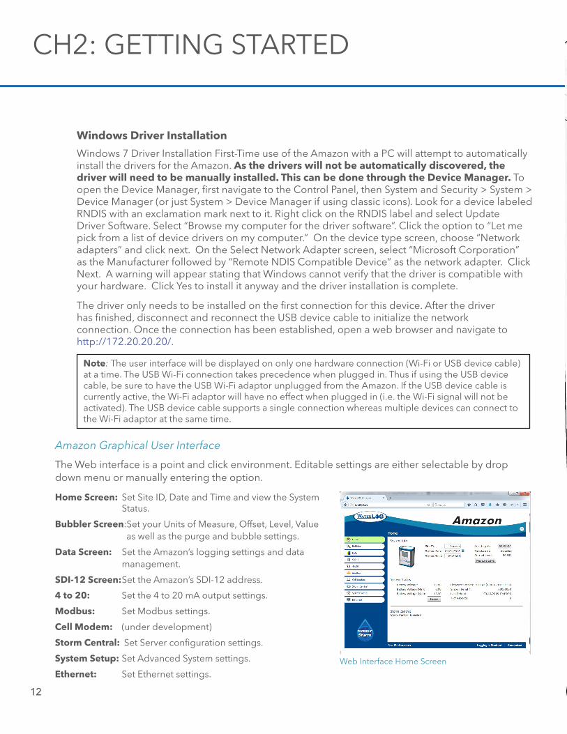
The Web interface is a point and click environment. Editable settings are either selectable by drop down menu or manually entering the option.
Web Interface Home Screen
Home Screen: Set Site ID, Date and Time and view the System Status.
Bubbler Screen:Set your Units of Measure, Offset, Level, Value as well as the purge and bubble settings.
Data Screen: Set the Amazon’s logging settings and data management.
SDI-12 Screen: Set the Amazon’s SDI-12 address.
4 to 20: Set the 4 to 20 mA output settings.
Modbus: Set Modbus settings.
Cell Modem: (under development)
Storm Central: Set Server configuration settings.
System Setup: Set Advanced System settings.
Ethernet: Set Ethernet settings.
Web Interface Home Screen
INSTALLATION03 /
13
CH3: INSTALLATION
14
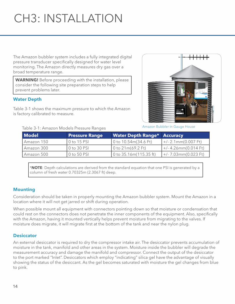
The Amazon bubbler system includes a fully integrated digital pressure transducer specifically designed for water level monitoring. The Amazon directly measures dry gas over a broad temperature range.
Water Depth
Table 3-1 shows the maximum pressure to which the Amazon is factory calibrated to measure.
Model Pressure Range Water Depth Range* AccuracyAmazon 150 0 to 15 PSI 0 to 10.54m(34.6 Ft) +/- 2.1mm(0.007 Ft)Amazon 300 0 to 30 PSI 0 to 21m(69.2 Ft) +/- 4.26mm(0.014 Ft)Amazon 500 0 to 50 PSI 0 to 35.16m(115.35 ft) +/- 7.03mm(0.023 Ft)
Table 3-1: Amazon Models Pressure Ranges
*NOTE: Depth calculations are derived from the standard equation that one PSI is generated by a column of fresh water 0.70325m (2.3067 ft) deep.
Mounting
Consideration should be taken in properly mounting the Amazon bubbler system. Mount the Amazon in a location where it will not get jarred or shift during operation.
When possible mount all equipment with connectors pointing down so that moisture or condensation that could rest on the connectors does not penetrate the inner components of the equipment. Also, specifically with the Amazon, having it mounted vertically helps prevent moisture from migrating to the valves. If moisture does migrate, it will migrate first at the bottom of the tank and near the nylon plug.
DesiccatorAn external desiccator is required to dry the compressor intake air. The desiccator prevents accumulation of moisture in the tank, manifold and other areas in the system. Moisture inside the bubbler will degrade the measurement accuracy and damage the manifold and compressor. Connect the output of the desiccator to the port marked “Inlet”. Desiccators which employ “indicating” silica gel have the advantage of visually showing the status of the desiccant. As the gel becomes saturated with moisture the gel changes from blue to pink.
Amazon Bubbler in Gauge House
WARNING! Before proceeding with the installation, please consider the following site preparation steps to help prevent problems later.
Orifice Line
Ch3: Installation
15
The position and installation of the orifice line is vital to a successful and accurate Amazon installation. These are just a few of several things to consider when installing or checking an orifice line installation. Refer to Appendix A and Application Note 1005 for more detailed information about orifice line installation (http://www.waterlog.com/media/pdfs/orifice-line-installation_001.pdf).
Be sure the water current or flow is not pushing against the end of the orifice line, as it will cause a pressure to be placed on the line that is not related to the water depth. Also, be sure the water current or flow is not pulling or drawing from the end of the orifice line, as this will cause a false lower pressure on the line not related to the water depth. The line should be installed in an area where the flow of water will remain relatively calm as compared to the real level changes. Here are a few Do’s and Do Not’s on mounting the line.
Do:• Mount the outlet in still water• Mount the outlet so the last inch or so is almost horizontal, with a slight downward slope• Try to prevent swells in long runs of orifice line
Do not:• Do not mount the outlet of the orifice line facing up stream, downstream, or upwards• Do not allow any portion of the line to be lower than the exit point• Do not allow “goose necks” in the orifice line• Do not use thin walled tubing, only use USGS approved* orifice line• Do not mount outlet of the orifice line in the wake of an obstruction, bridge pier, rock, etc.
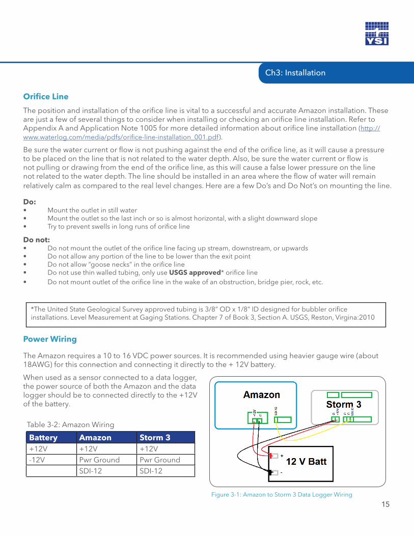
Power Wiring
When used as a sensor connected to a data logger, the power source of both the Amazon and the data logger should be to connected directly to the +12V of the battery.
Battery Amazon Storm 3+12V +12V +12V-12V Pwr Ground Pwr Ground
SDI-12 SDI-12
Table 3-2: Amazon Wiring
Figure 3-1: Amazon to Storm 3 Data Logger Wiring
*The United State Geological Survey approved tubing is 3/8” OD x 1/8” ID designed for bubbler orifice installations. Level Measurement at Gaging Stations. Chapter 7 of Book 3, Section A. USGS, Reston, Virgina:2010
The Amazon requires a 10 to 16 VDC power sources. It is recommended using heavier gauge wire (about 18AWG) for this connection and connecting it directly to the + 12V battery.
Amazon Bubbler in Gauge House
SETUP & OPERATION - SOFTWARE04 /
16
17
There are three ways to setup the Amazon bubbler system; through the software interface, the SDI-12 interface, and through the keypad display interface. This chapter will focus on setup using the software interface. The keypad display is covered in chapter 5 and the SDI-12 commands are covered in chapter 6.
Software Interface
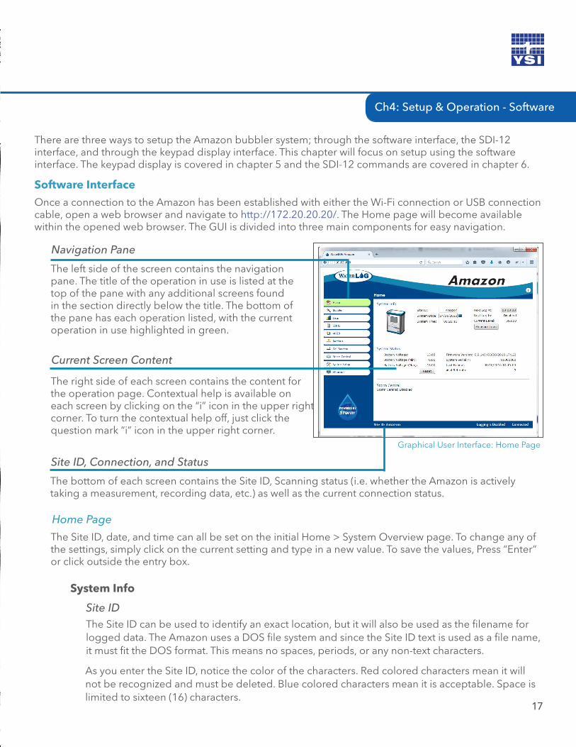
Once a connection to the Amazon has been established with either the Wi-Fi connection or USB connection cable, open a web browser and navigate to http://172.20.20.20/. The Home page will become available within the opened web browser. The GUI is divided into three main components for easy navigation.
The left side of the screen contains the navigation pane. The title of the operation in use is listed at the top of the pane with any additional screens found in the section directly below the title. The bottom of the pane has each operation listed, with the current operation in use highlighted in green.
Navigation Pane
The right side of each screen contains the content for the operation page. Contextual help is available on each screen by clicking on the “i” icon in the upper right corner. To turn the contextual help off, just click the question mark “i” icon in the upper right corner.
Current Screen Content
The bottom of each screen contains the Site ID, Scanning status (i.e. whether the Amazon is actively taking a measurement, recording data, etc.) as well as the current connection status.
Site ID, Connection, and Status
Home Page
The Site ID, date, and time can all be set on the initial Home > System Overview page. To change any of the settings, simply click on the current setting and type in a new value. To save the values, Press “Enter” or click outside the entry box.
The Site ID can be used to identify an exact location, but it will also be used as the filename for logged data. The Amazon uses a DOS file system and since the Site ID text is used as a file name, it must fit the DOS format. This means no spaces, periods, or any non-text characters.
System Info
As you enter the Site ID, notice the color of the characters. Red colored characters mean it will not be recognized and must be deleted. Blue colored characters mean it is acceptable. Space is limited to sixteen (16) characters.
Site ID
Ch4: Setup & Operation - Software
Graphical User Interface: Home Page
Clicking either the box or the calendar icon will bring a monthly calendar forward. Just click on the current day and the date will be set.
System Date
The System Time format is in a 24-hour notation (hh:mm:ss). Once the time is set, the clock will wait to begin counting until Enter is pressed or clicking anywhere outside the box.
System Time
The Next Log Time format is in a 24-hour notation (hh:mm:ss). This time represents the next time the Amazon will scan the line pressure and record the value measured.
Next Log At
When logging is enabled, the 24-hour notation clock will count down how long before the next measurement will be recorded scan will occur.
Next Log In
The most recent measured value is displayed. The units displayed represent the units of measurements selected in Level Units of the Bubbler section.
Current Level
The system Status section is mainly used to verify the operation of the Amazon.
System Status
The Amazon displays the current battery voltage from the systems +12 VDC input. Even though the battery voltage display will briefly rise and fall, the only voltage reading saved to your data will be at each logging interval.
Battery Voltage
Each time the Amazon measures the battery voltage it checks to see if the current voltage is less than the minimum value detected and then updates the minimum value if needed. This value is mainly provided as a diagnostic tool to help understand system performance and reliability. If the minimum voltage is too low it may indicate that the battery is being undercharged. See “Reset” below for more information.
Battery Voltage (Min)
Selecting the Measure Level button will initiate a measurement and update the Current Level displayed.
Measure Level
18
CH4: SETUP & OPERATION - SOFTWARE
19
Each time the Amazon measures the battery voltage it checks to see if the current voltage is greater than the maximum value detected and then updates the maximum value if needed. A high value may indicate a faulty regulator. See “Reset” below for more information.
Battery Voltage (Max)
This is the current firmware the Amazon is running. You may be asked to provide the firmware version if you should require technical assistance.
Firmware Version
The system serial number displays the Amazon serial number. You may be asked to provide the serial number if you should require technical assistance. This number should match the serial number printed on the product label found on the Amazon.
System Serial #
The Amazon Last Reboot will be listed with date and time. Even when the system status has been reset, the last reboot will always be listed.
Last Reboot
This is a status update that lists how many times the system has reset since the last system reset. A reboot can be caused by several conditions, low battery and power spikes, power glitches, and power disconnects are the most common.
# of Reboots
The reset option is used to reset the minimum and maximum battery values, and the system reboot counter to 0. The intended use of this option is to provide information on how the system is operating between field trips. It is recommended to reset the status screens at the end of each field trip. Then, on arrival of the next field trip, the first task would be to view these numbers to see if any unexpected conditions occurred since the last trip. Ideally, the number of resets would still be zero and the min and max battery values would be within the normal operating range.
Reset
If the Amazon has been connected to the internet via the Ethernet port, then logged data can be pushed to Storm Central Data Hosting. Refer to the Storm Central Getting Started Guide (http://www.waterlog.com/media/pdfs/storm-central-getting-started-guide-(d27-02-0514).pdf). When setting up Storm Central, it currently only provides settings for GOES or cell modem connections. To use the Amazon with its current Ethernet IP communication, setup Storm Central as if it were a cell modem connection.
Storm Central
The Storm Central functions of the Amazon can be set to either the Enabled or Disabled mode.Storm Central
Ch4: Setup & Operation - Software
The date and time of the next transmission are displayed. This indicates the next time data from the Amazon will be pushed to Storm Central.
Next Tx
The date and time of the last transmission are displayed. This indicates the last time data from the Amazon was pushed to Storm Central.
Last Tx
The date and time the last transmission actually occurred. This will normally be slightly after the Last Tx.
Actual Tx
A text description of the last transmission status. Examples: "Successfully transmit x rows" or "Battery was too low to connect to server. Voltage=yy.yy".
Last Tx Status
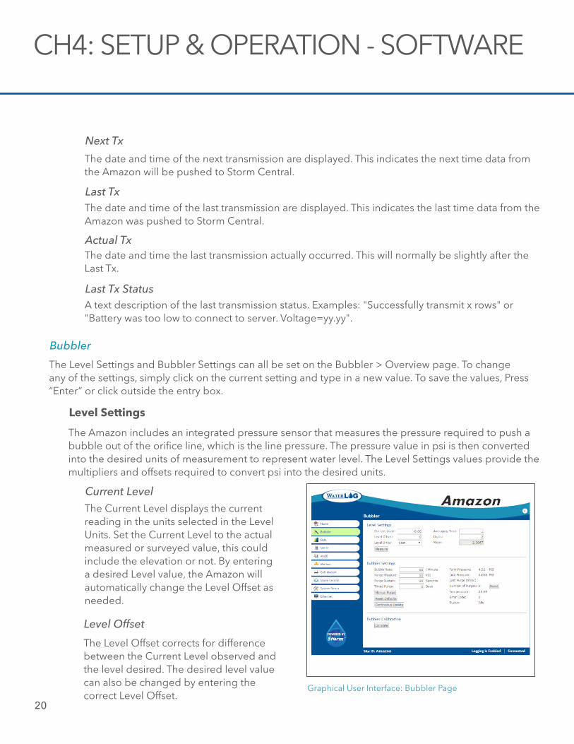
The Level Settings and Bubbler Settings can all be set on the Bubbler > Overview page. To change any of the settings, simply click on the current setting and type in a new value. To save the values, Press “Enter” or click outside the entry box.
Bubbler
The Amazon includes an integrated pressure sensor that measures the pressure required to push a bubble out of the orifice line, which is the line pressure. The pressure value in psi is then converted into the desired units of measurement to represent water level. The Level Settings values provide the multipliers and offsets required to convert psi into the desired units.
Level Settings
The Current Level displays the current reading in the units selected in the Level Units. Set the Current Level to the actual measured or surveyed value, this could include the elevation or not. By entering a desired Level value, the Amazon will automatically change the Level Offset as needed.
Current Level
The Level Offset corrects for difference between the Current Level observed and the level desired. The desired level value can also be changed by entering the correct Level Offset.
Level Offset
Graphical User Interface: Bubbler Page
CH4: SETUP & OPERATION - SOFTWARE
20
Ch4: Setup & Operation - Software
21
Level Units are the units of measure of the Current Level. These units will also be displayed on the key pad display. Level Units are selected from a pull down menu. When the desired units are selected from the menu, the Amazon provides the corrected slope value. The values used for conversion assumes fresh water. Use the user selected values for slope and offset if adjustments need to be made for water density variations.
Level Units
On the timed logging interval, external logging interval, or manual measurement request, a measurement is initiated by the Amazon. The Amazon will measure as fast as possible and then calculate the average of these readings to obtain the recorded or returned value. The longer the Averaging Time selected (entered as seconds), the more samples will be used in calculating the average. The speed at which the Amazon can obtain the samples will vary depending on several signal processing conditions. However, this frequency of samples will be between 10 and 20 samples per second. The Averaging Time can range between 1 and 360 seconds.
Averaging Time
Select the number of digits the level or level reading will be displayed in. This refers to the number of digits after the decimal. This value must be between 2 and 6.
Digits
The Slope is calculated by the Amazon to reflect the Level Units selected. Or a user selected slope can be entered here.
Slope
The Measure button initiates an immediate measurement.Measure
For optimal performance under varying conditions, the Amazon provides the ability to fine-tune the bubble rate and purge functions. Where the bubble rate is directly related to the measurement, the purge functions are used to clear the orifice line of any obstructions. The purge functions can be initiated manually, on a time interval, or as an SDI-12 command.
Bubbler Settings
Depending on the conditions at the site, the optimal bubbler rate will vary. This rate can be selected between 10 and 120 bubbles per minute (BPM). 60 BPM is typically used for most applications.
Bubble Rate
Purging forces a blast of air through the orifice line in order to remove any sediment or debris from the line. A line that has restriction due to obstructions can provide a false pressure reading. The pressure at which the Amazon purges the line during the purge process can be set between 40 and 90 PSI. Generally 50 PSI is adequate. Where conditions are heavily silted, a higher PSI may be needed.
Purge Pressure
The time that the purge is sustained can be selected between 10 and 30 seconds. Like the purge pressure, some conditions require a longer or shorter purge time. Generally 20 seconds is adequate. Longer purge times will require higher power usage from the battery.
Purge Sustain
The Amazon can be set to purge automatically. If the timed purge is not required, set the Timed Purge to 0. Time Purge is configured on a daily schedule. The frequency to purge can be set from 0 to 90 days in whole day increments. Timed Purge is activated just after noon. If 5 is entered, the purge function will activate every 5th day just after noon.
Timed Purge
Selecting the Manual Purge button will initiate the purge function based on the Purge Pressure and Purge Sustain values selected.
Manual Purge
For most applications, the Bubble and Purge settings provided at the factory are ideal. It's easy to reset changes made back to the factory settings by selecting the Reset Defaults button.
Reset Defaults
By selecting the Continuous Update button, all values under the Bubbler Settings section are measured and displayed. This is a continual measurement. Once the Continuous Update button is selected, the display will keep providing current Status data until the Stop button is selected or a new page is displayed.
Continuous Update
Understanding the Tank Pressure can be very helpful in verifying your Amazon is working correctly. The Tank Pressure is the pressure (displayed in PSI units) of the air inside the tank. This pressure should always be at least 2 PSI’s greater than the Line Pressure. The Amazon is a continuous bubbler, meaning that a bubble of air is continually being forced through the orifice line. To allow this to be continual, the tank pressure must always be greater than the pressure of the water above the outlet to the orifice line (head).
Tank Pressure
The Line Pressure is pressure measured in the orifice line.
Line Pressure
Regardless if a manual purge, timed purge, or programmed purge occurs, the time and date of the last purge will be displayed.
Last Purge (Time)
The number of times the Amazon has purged will be displayed. This values reset to zero when the Reset Button is selected.
Number of Purges
CH4: SETUP & OPERATION - SOFTWARE
22The Reset Button clears the Number of Purges back to zero.Reset
Ch4: Setup & Operation - Software
23
The temperature of the main circuit board of the Amazon is displayed. The units are selected on in the Systems Setup page.
Temperature
The Amazon is continually monitoring its own functions and health. The numbers displayed represent an error code to determine which functions are not performing properly. In addition to the error code, a directive is provided on the Home Screen. There are four directive that may be posted: User Service, Factory Service, Call Support, Set Clock. You may be asked to provide this information if you should require technical assistance. Refer to Appendix B for an description of the error codes.
Error Code
The Status provides the current state of the Amazon. In most situations this will display “Idle”. The text will change to “Measuring” during a measurement cycle and “Purging” during a purge cycle. These values will change when Update Values button has been selected.
Status
The bubbler calibration does not calibrate the Amazon. This function is for verification of the pressure sensor from an external pressure device. This is commonly used as a field verification tool to insure that the pressure sensor is providing accurate readings. Attach an external pressure source to the Amazon output port. With the pressure applied, push the Calibrate button on the Screen or Cal button on the Amazon front panel. This will disengage the Amazon compressor from the line and measure the pressure applied. The value on the display should be the same as the pressure applied.
Bubbler Calibration
The Status provides the current state.
Calibrate
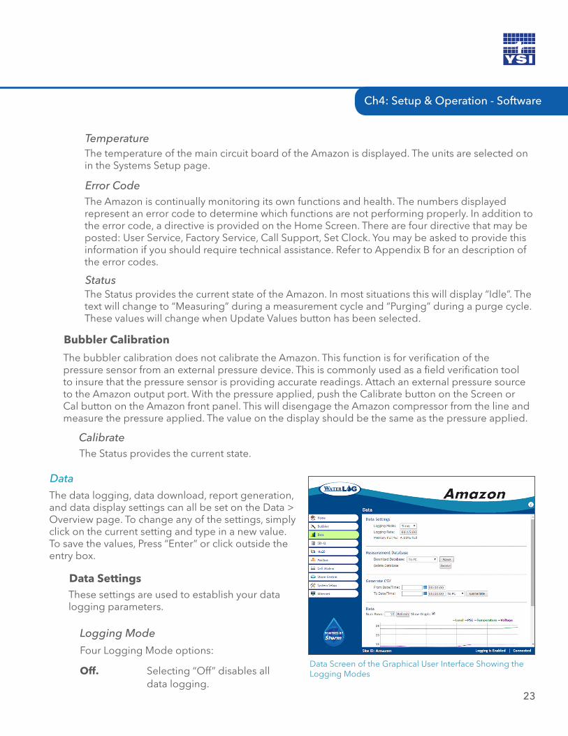
The data logging, data download, report generation, and data display settings can all be set on the Data > Overview page. To change any of the settings, simply click on the current setting and type in a new value. To save the values, Press “Enter” or click outside the entry box.
Data
These settings are used to establish your data logging parameters.
Data Settings
Logging Mode
Data Screen of the Graphical User Interface Showing the Logging Modes
Four Logging Mode options:
Off. Selecting “Off” disables all data logging.
24
The rate at which data is recorded is entered in 24-hour notations (hh:mm:ss). In the example 00:01:00, data will be recorded every minute. The logging rate must be between 1 minute and 24 hours. As you enter the Logging Rate, notice the color of each character. A red colored character means it will not be recognized.
Logging Rate
The Amazon provides 260 MB of memory. Under typical circumstances, this should provide enough memory to last for years. The units represented are the percentage of memory that has been used.
Memory Full %
The entire recorded data file of the Amazon can be down loaded in a SQLite data base file format.
Measurement Database
This is a selectable field. Choose which device you would like to down load stored date to. This can be directly to a PC (the Amazon is connected to a PC via the Wi-Fi, USB, or Ethernet ports) or data can be down loaded directly to a USB Flash Drive connected to the USB port on the Amazon.
Download Database
After the desired database has been selected, press the Save button. This will initiate data download.
Save
The entire data memory of the Amazon can be cleared by selecting the Delete button. Caution should be taken before selecting this button. All data should be downloaded first to a PC or USB Flash Drive before deleting the data from memory.
Delete Database
CH4: SETUP & OPERATION - SOFTWARE
The more common and user friendly format for retrieving data from the Amazon is in the Comma Separate Values (CSV) format. The selected section of the data set can be retrieved and copied directly to the PC or to a USB Flash Drive.
Generate CSV
Select the beginning date and time of the first record in the data set to be retrieved. Time is the 24-hour (hh:mm:ss) format.
From Data/Time
Timed. The “Timed” mode enables data values to be recorded on a timed interval called the Logging Rate. When this mode is selected the Amazon will record data at each timed interval.
External Only. When External Logging Mode is enabled, the Amazon will record the measured data each time it receives an SDI-12 Command from a SDI-12 Recorder.
Timed+External. Both the Timed and External Logging Modes are enabled.
Ch4: Setup & Operation - Software
25
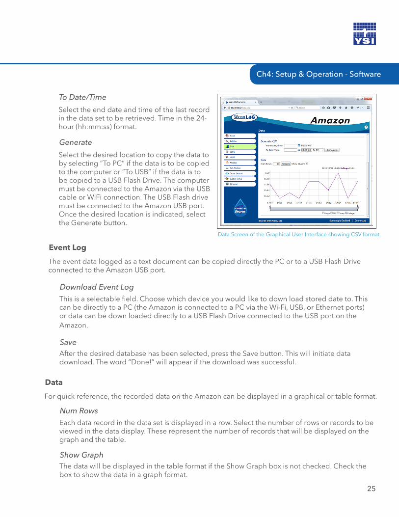
Data Screen of the Graphical User Interface showing CSV format.
Select the end date and time of the last record in the data set to be retrieved. Time in the 24-hour (hh:mm:ss) format.
To Date/Time
Select the desired location to copy the data to by selecting “To PC” if the data is to be copied to the computer or “To USB” if the data is to be copied to a USB Flash Drive. The computer must be connected to the Amazon via the USB cable or WiFi connection. The USB Flash drive must be connected to the Amazon USB port. Once the desired location is indicated, select the Generate button.
Generate
For quick reference, the recorded data on the Amazon can be displayed in a graphical or table format.
Data
Each data record in the data set is displayed in a row. Select the number of rows or records to be viewed in the data display. These represent the number of records that will be displayed on the graph and the table.
Num Rows
The data will be displayed in the table format if the Show Graph box is not checked. Check the box to show the data in a graph format.
Show Graph
The event data logged as a text document can be copied directly the PC or to a USB Flash Drive connected to the Amazon USB port.
Event Log
This is a selectable field. Choose which device you would like to down load stored date to. This can be directly to a PC (the Amazon is connected to a PC via the Wi-Fi, USB, or Ethernet ports) or data can be down loaded directly to a USB Flash Drive connected to the USB port on the Amazon.
Download Event Log
After the desired database has been selected, press the Save button. This will initiate data download. The word “Done!” will appear if the download was successful.
Save
The Amazon supports all standard SDI-12 commands and uses some SDI-12 extended commands for setup operation. SDI-12 standard and extended commands are normally sent from a SDI-12 master device (recorder) like the Storm 3 data logger. Chaper 6 covers these commands in detail.
SDI-12
SDi-12 Screen of the Graphical User Interface
Multiple SDI-12 slaves can be connected to a single SDI-12 master. Each SDI-12 slave is identified by a unique address. The Amazon is an SDI-12 slave so must have a unique address.
SDI-12 Settings
Acceptable address are a to z, 0 to 9, and A to Z.SDI-12 Address
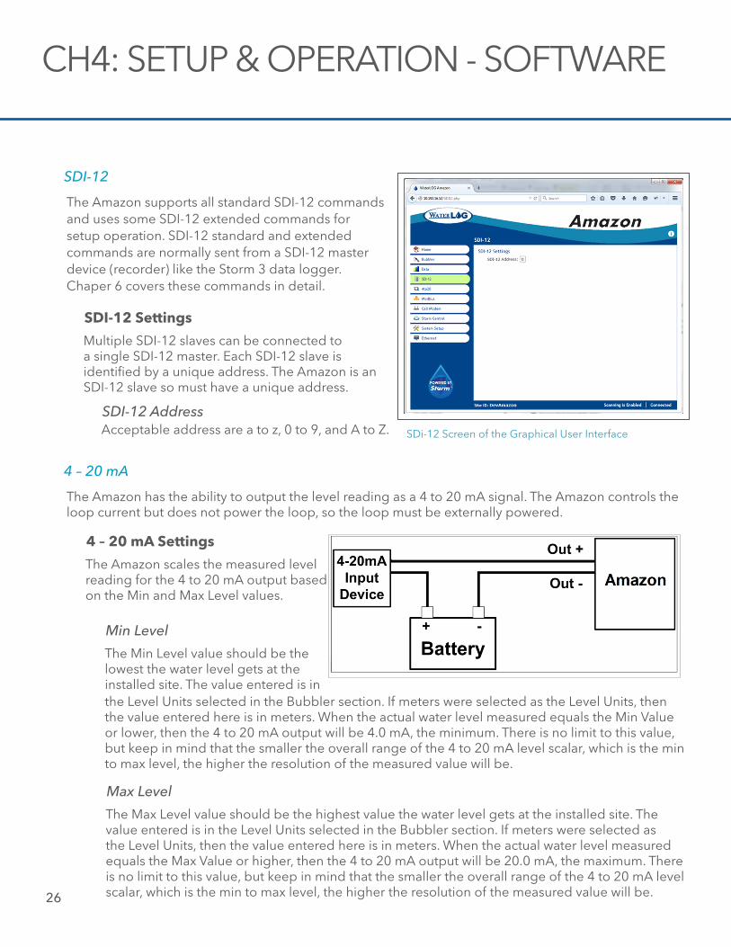
The Amazon has the ability to output the level reading as a 4 to 20 mA signal. The Amazon controls the loop current but does not power the loop, so the loop must be externally powered.
4 – 20 mA
The Amazon scales the measured level reading for the 4 to 20 mA output based on the Min and Max Level values.
4 – 20 mA Settings
The Min Level value should be the lowest the water level gets at the installed site. The value entered is in
Min Level
the Level Units selected in the Bubbler section. If meters were selected as the Level Units, then the value entered here is in meters. When the actual water level measured equals the Min Value or lower, then the 4 to 20 mA output will be 4.0 mA, the minimum. There is no limit to this value, but keep in mind that the smaller the overall range of the 4 to 20 mA level scalar, which is the min to max level, the higher the resolution of the measured value will be.
The Max Level value should be the highest value the water level gets at the installed site. The value entered is in the Level Units selected in the Bubbler section. If meters were selected as the Level Units, then the value entered here is in meters. When the actual water level measured equals the Max Value or higher, then the 4 to 20 mA output will be 20.0 mA, the maximum. There is no limit to this value, but keep in mind that the smaller the overall range of the 4 to 20 mA level scalar, which is the min to max level, the higher the resolution of the measured value will be.
Max Level
26
CH4: SETUP & OPERATION - SOFTWARE
4-20 Screen of the Graphical User Interface
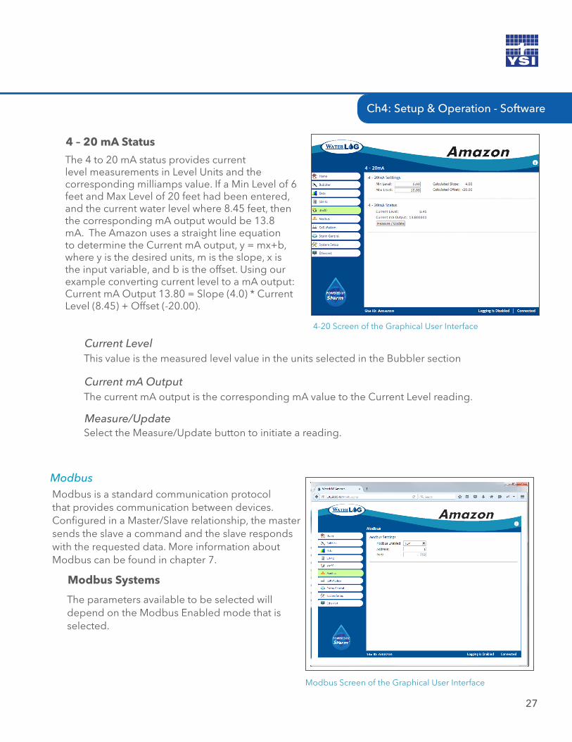
The 4 to 20 mA status provides current level measurements in Level Units and the corresponding milliamps value. If a Min Level of 6 feet and Max Level of 20 feet had been entered, and the current water level where 8.45 feet, then the corresponding mA output would be 13.8 mA. The Amazon uses a straight line equation to determine the Current mA output, y = mx+b, where y is the desired units, m is the slope, x is the input variable, and b is the offset. Using our example converting current level to a mA output: Current mA Output 13.80 = Slope (4.0) * Current Level (8.45) + Offset (-20.00).
4 – 20 mA Status
This value is the measured level value in the units selected in the Bubbler sectionCurrent Level
The current mA output is the corresponding mA value to the Current Level reading. Current mA Output
Select the Measure/Update button to initiate a reading. Measure/Update
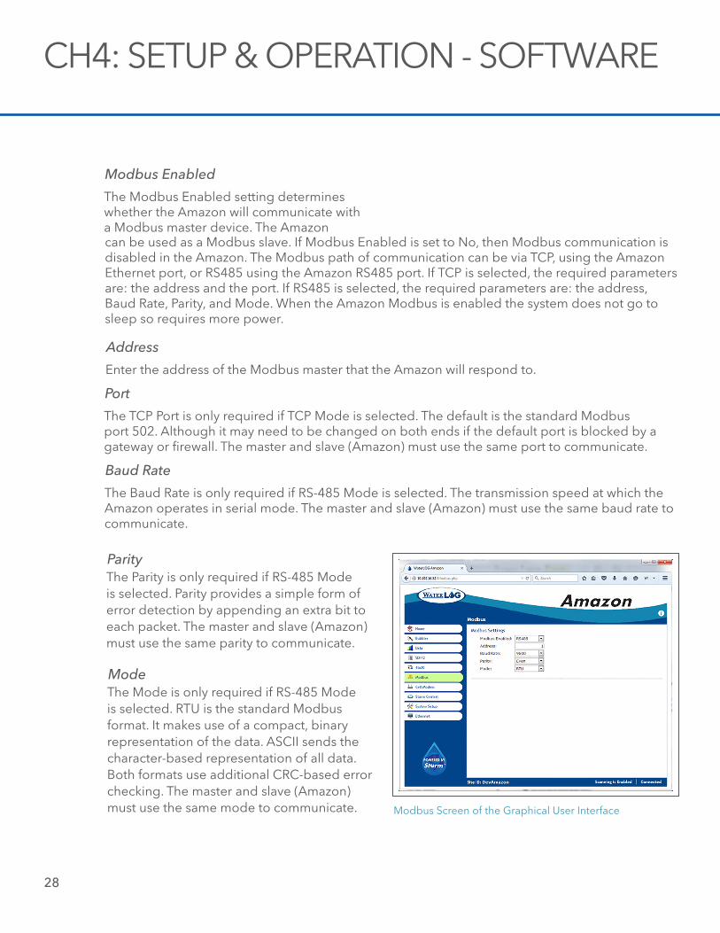
Modbus is a standard communication protocol that provides communication between devices. Configured in a Master/Slave relationship, the master sends the slave a command and the slave responds with the requested data. More information about Modbus can be found in chapter 7.
Modbus
Modbus Systems
The parameters available to be selected will depend on the Modbus Enabled mode that is selected.
Modbus Screen of the Graphical User Interface
Ch4: Setup & Operation - Software
27
28
CH4: SETUP & OPERATION - SOFTWARE
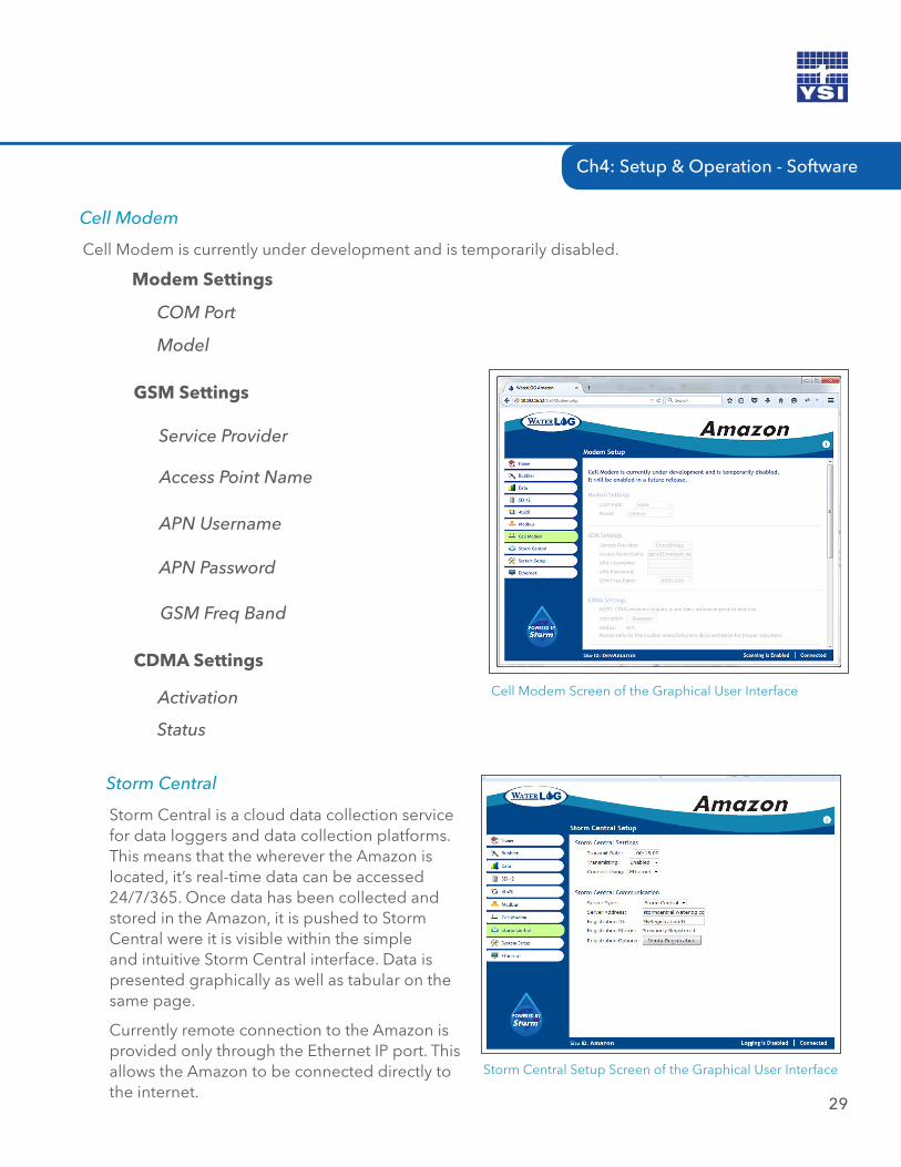
The Modbus Enabled setting determines whether the Amazon will communicate with a Modbus master device. The Amazon
Modbus Enabled
can be used as a Modbus slave. If Modbus Enabled is set to No, then Modbus communication is disabled in the Amazon. The Modbus path of communication can be via TCP, using the Amazon Ethernet port, or RS485 using the Amazon RS485 port. If TCP is selected, the required parameters are: the address and the port. If RS485 is selected, the required parameters are: the address, Baud Rate, Parity, and Mode. When the Amazon Modbus is enabled the system does not go to sleep so requires more power.
Enter the address of the Modbus master that the Amazon will respond to.
Address
The TCP Port is only required if TCP Mode is selected. The default is the standard Modbus port 502. Although it may need to be changed on both ends if the default port is blocked by a gateway or firewall. The master and slave (Amazon) must use the same port to communicate.
Port
The Baud Rate is only required if RS-485 Mode is selected. The transmission speed at which the Amazon operates in serial mode. The master and slave (Amazon) must use the same baud rate to communicate.
Baud Rate
Modbus Screen of the Graphical User Interface
The Parity is only required if RS-485 Mode is selected. Parity provides a simple form of error detection by appending an extra bit to each packet. The master and slave (Amazon) must use the same parity to communicate.
Parity
The Mode is only required if RS-485 Mode is selected. RTU is the standard Modbus format. It makes use of a compact, binary representation of the data. ASCII sends the character-based representation of all data. Both formats use additional CRC-based error checking. The master and slave (Amazon) must use the same mode to communicate.
Mode
Ch4: Setup & Operation - Software
29
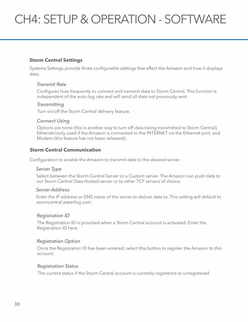
Cell Modem is currently under development and is temporarily disabled.
Cell Modem
Modem Settings
COM Port
Model
Cell Modem Screen of the Graphical User Interface
GSM Settings
Service Provider
Access Point Name
APN Username
APN Password
GSM Freq Band
CDMA Settings
Activation
Status
Storm Central is a cloud data collection service for data loggers and data collection platforms. This means that the wherever the Amazon is located, it’s real-time data can be accessed 24/7/365. Once data has been collected and stored in the Amazon, it is pushed to Storm Central were it is visible within the simple and intuitive Storm Central interface. Data is presented graphically as well as tabular on the same page.
Currently remote connection to the Amazon is provided only through the Ethernet IP port. This allows the Amazon to be connected directly to the internet.
Storm Central
Storm Central Setup Screen of the Graphical User Interface
30
CH4: SETUP & OPERATION - SOFTWARE
Configures how frequently to connect and transmit data to Storm Central. This function is independent of the auto-log rate and will send all data not previously sent.
Storm Central Settings
Systems Settings provide three configurable settings that affect the Amazon and how it displays data.
Transmit Rate
Transmitting
Connect Using
Turn on/off the Storm Central delivery feature.
Options are none (this is another way to turn off data being transmitted to Storm Central), Ethernet (only used if the Amazon is connected to the INTERNET via the Ethernet port, and Modem (this feature has not been released).
Storm Central Communication
Configuration to enable the Amazon to transmit data to the desired server.
Server Type
Server Address
Select between the Storm Central Server or a Custom server. The Amazon can push data to our Storm Central Data Hosted server or to other TCP servers of choice.
Enter the IP address or DNS name of the server to deliver data to. This setting will default to stormcentral.waterlog.com.
Registration IDThe Registration ID is provided when a Storm Central account is activated. Enter the Registration ID here.
Registration OptionOnce the Registration ID has been entered, select this button to register the Amazon to this account.
Registration StatusThe current status if the Storm Central account is currently registered or unregistered.
31
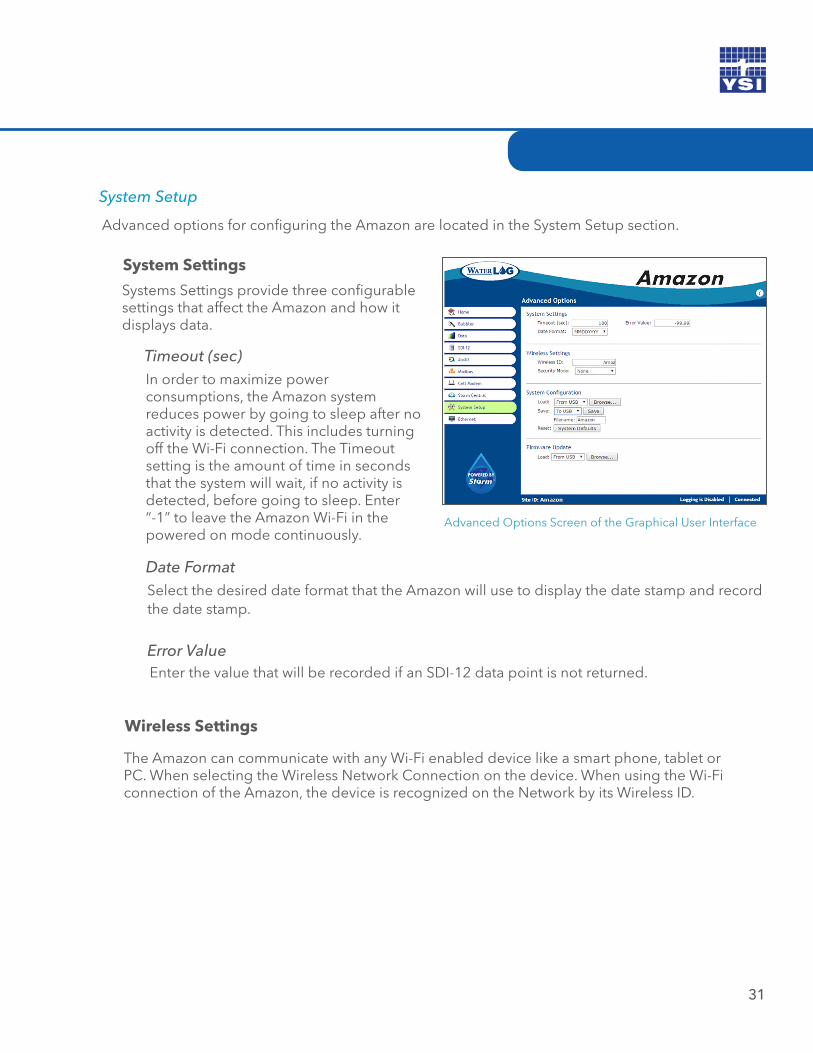
Advanced options for configuring the Amazon are located in the System Setup section.
System Setup
Advanced Options Screen of the Graphical User Interface
System Settings
Systems Settings provide three configurable settings that affect the Amazon and how it displays data.
Timeout (sec)In order to maximize power consumptions, the Amazon system reduces power by going to sleep after no activity is detected. This includes turning off the Wi-Fi connection. The Timeout setting is the amount of time in seconds that the system will wait, if no activity is detected, before going to sleep. Enter “-1” to leave the Amazon Wi-Fi in the powered on mode continuously.
Date FormatSelect the desired date format that the Amazon will use to display the date stamp and record the date stamp.
Error ValueEnter the value that will be recorded if an SDI-12 data point is not returned.
Wireless Settings
The Amazon can communicate with any Wi-Fi enabled device like a smart phone, tablet or PC. When selecting the Wireless Network Connection on the device. When using the Wi-Fi connection of the Amazon, the device is recognized on the Network by its Wireless ID.
32
CH4: SETUP & OPERATION - SOFTWARE
Wireless IDEnter the ID name that will identify the Amazon bubbler on the Wireless Network Connection. The name of the Wireless ID has no length restrictions and can contain letters, numbers, hyphen, underscore, and period.
Security ModeThe Amazon provides a security gate into the functionality of the system. WPA2, WPA, WPA+WPA2 must be consistent with your modem or router settings. When Security Mode in enabled the Pass Phrase becomes available.
System Configuration
The Amazon creates a configuration file of the settings selected when configuring the system. This file can be copied to a PC, USB Flash Drive, or the Amazon. The configuration file can then be down loaded onto another Amazon bubbler so that exact same configurations are used on each Amazon.
LoadThe Load selection box provides three location from which to retrieve a configuration file and load it onto the Amazon; From the PC, from the USB Flash Drive that is connected to the Amazon USB port, and from the Amazon. This allows multiple configuration files to be stored and retrieved as needed.
SaveThe Save selection box provides three location from which to save a configuration file created on the Amazon; to the PC, to the USB Flash Drive that is connected to the Amazon USB port, and to the Amazon.
ResetSelecting the Systems Default button resets all Amazon configuration settings to their original factory state.
Firmware Update
There are several reasons to install a new Firmware on the Amazon. These include replacing a firmware that has become corrupted or installing a newly released firmware. All Amazon firmware versions are available on www.waterlog.com/software-archive/. These files can be copied to a PC or to a USB Flash Drive. From these storage devices the firmware can be loaded to the Amazon.
Pass PhraseEntered the desired Pass Phrase to limit entry through the Wi-Fi connection. Once a pass phrase has been selected, it will be required on the smart phone, tablet, or PC. WPA specs require the pass phrase to be between 8 and 63 printable characters.
Ch4: Setup & Operation - Software
33
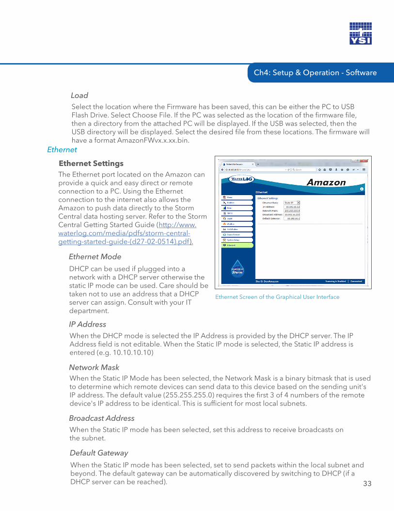
Ethernet
Ethernet SettingsThe Ethernet port located on the Amazon can provide a quick and easy direct or remote connection to a PC. Using the Ethernet connection to the internet also allows the Amazon to push data directly to the Storm Central data hosting server. Refer to the Storm Central Getting Started Guide (http://www.waterlog.com/media/pdfs/storm-central-getting-started-guide-(d27-02-0514).pdf).
Ethernet Screen of the Graphical User Interface
Ethernet Mode
DHCP can be used if plugged into a network with a DHCP server otherwise the static IP mode can be used. Care should be taken not to use an address that a DHCP server can assign. Consult with your IT department.
IP AddressWhen the DHCP mode is selected the IP Address is provided by the DHCP server. The IP Address field is not editable. When the Static IP mode is selected, the Static IP address is entered (e.g. 10.10.10.10)
Network MaskWhen the Static IP Mode has been selected, the Network Mask is a binary bitmask that is used to determine which remote devices can send data to this device based on the sending unit's IP address. The default value (255.255.255.0) requires the first 3 of 4 numbers of the remote device's IP address to be identical. This is sufficient for most local subnets.
Broadcast AddressWhen the Static IP mode has been selected, set this address to receive broadcasts on the subnet.
Default Gateway
When the Static IP mode has been selected, set to send packets within the local subnet and beyond. The default gateway can be automatically discovered by switching to DHCP (if a DHCP server can be reached).
LoadSelect the location where the Firmware has been saved, this can be either the PC to USB Flash Drive. Select Choose File. If the PC was selected as the location of the firmware file, then a directory from the attached PC will be displayed. If the USB was selected, then the USB directory will be displayed. Select the desired file from these locations. The firmware will have a format AmazonFWvx.x.xx.bin.
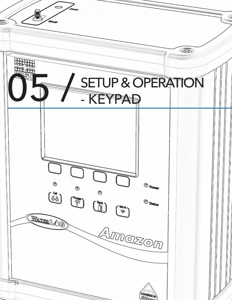
05 / SETUP & OPERATION - KEYPAD
34
35
Ch5: Setup & Operation - Keypad
There are three ways to setup the Amazon bubbler system; through the software interface, the SDI-12 interface, and through the keypad display interface. This chapter will focus on setup using keypad display. The software is covered in chapter 4, and the SDI-12 commands are covered in chapter 6.
Keypad - Display
The Amazon’s optional keypad display provides complete functionality required to configure the Amazon, retrieve logged data, and configure communication settings.
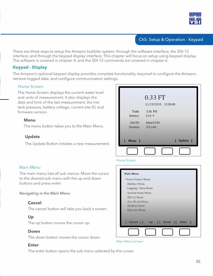
The Home Screen displays the current water level and units of measurement. It also displays the date and time of the last measurement, the live tank pressure, battery voltage, current site ID, and firmware version.
Home Screen
Menu The menu button takes you to the Main Menu.
Home Screen
Update
The Update Button initiates a new measurement.
Navigating in the Main Menu
CancelThe cancel button will take you back a screen.
UpThe up button moves the cursor up.
DownThe down button moves the cursor down.
EnterThe enter button opens the sub menu selected by the cursor.
The main menu lists all sub menus. Move the cursor to the desired sub menu with the up and down buttons and press enter.
Main Menu
Main Menu Screen
36
CH5: SETUP & OPERATION - KEYPAD
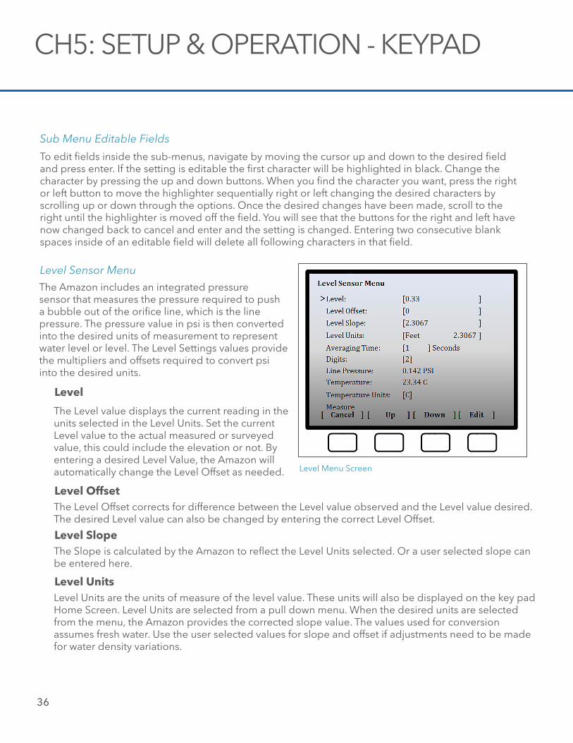
The Amazon includes an integrated pressure sensor that measures the pressure required to push a bubble out of the orifice line, which is the line pressure. The pressure value in psi is then converted into the desired units of measurement to represent water level or level. The Level Settings values provide the multipliers and offsets required to convert psi into the desired units.
Level Sensor Menu
Level
The Level value displays the current reading in the units selected in the Level Units. Set the current Level value to the actual measured or surveyed value, this could include the elevation or not. By entering a desired Level Value, the Amazon will automatically change the Level Offset as needed.
Level OffsetThe Level Offset corrects for difference between the Level value observed and the Level value desired. The desired Level value can also be changed by entering the correct Level Offset.
Level SlopeThe Slope is calculated by the Amazon to reflect the Level Units selected. Or a user selected slope can be entered here.
Level UnitsLevel Units are the units of measure of the level value. These units will also be displayed on the key pad Home Screen. Level Units are selected from a pull down menu. When the desired units are selected from the menu, the Amazon provides the corrected slope value. The values used for conversion assumes fresh water. Use the user selected values for slope and offset if adjustments need to be made for water density variations.
Level Menu Screen
Sub Menu Editable Fields
To edit fields inside the sub-menus, navigate by moving the cursor up and down to the desired field and press enter. If the setting is editable the first character will be highlighted in black. Change the character by pressing the up and down buttons. When you find the character you want, press the right or left button to move the highlighter sequentially right or left changing the desired characters by scrolling up or down through the options. Once the desired changes have been made, scroll to the right until the highlighter is moved off the field. You will see that the buttons for the right and left have now changed back to cancel and enter and the setting is changed. Entering two consecutive blank spaces inside of an editable field will delete all following characters in that field.
Ch5: Setup & Operation - Keypad
37
On the logging interval, programmed request, or manual request, a measurement is initiated by the Amazon. The Amazon will measure as fast as possible and then calculate the average of these readings to obtain the recorded or returned value. The longer the Averaging Time selected (entered as seconds), the more samples will be used in calculating the average. The speed at which the Amazon can obtain the samples will vary depending on several signal processing conditions. However, this frequency of samples will be between 10 and 20 samples per second. The Averaging Time can range between 1 and 360 seconds.
Averaging Time
DigitsSelect the number of digits the level reading will be displayed in. This refers to the number of digits after the decimal. This value must be between 2 and 6.
Line PressureThe Line Pressure in PSI for the orifice tube.
TemperatureTemperature displayed is of the main circuit board of the Amazon. This represents the internal temperature of the Amazon.
Temperature UnitsEnter the units in which the temperature will be displayed and recorded.
MeasureSelecting Measure will initiate the Amazon to take a new measurement.
For optimal performance under varying conditions, the Amazon provides the ability to fine-tune the bubble rate and purge functions. Where the bubble rate is directly related to the measurement, the purge functions are used to clear the orifice line of any obstructions. The purge functions can be initiated manually, on a time interval, or as an SDI-12 command (see chapter 6) in the programming of an external data logger. The main menu lists all sub menus. Move the cursor to the desired sub menu with the up and down buttons and press enter.
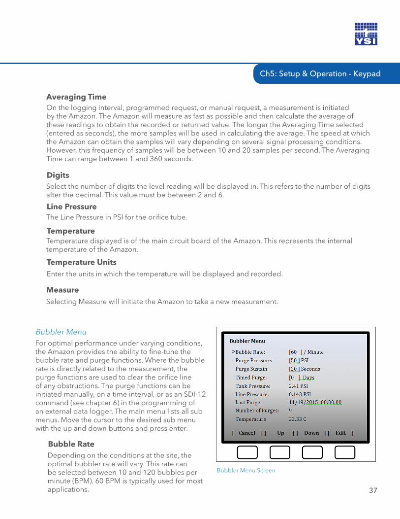
Bubbler Menu
Bubbler Menu Screen
Bubble RateDepending on the conditions at the site, the optimal bubbler rate will vary. This rate can be selected between 10 and 120 bubbles per minute (BPM). 60 BPM is typically used for most applications.
38
CH5: SETUP & OPERATION - KEYPAD
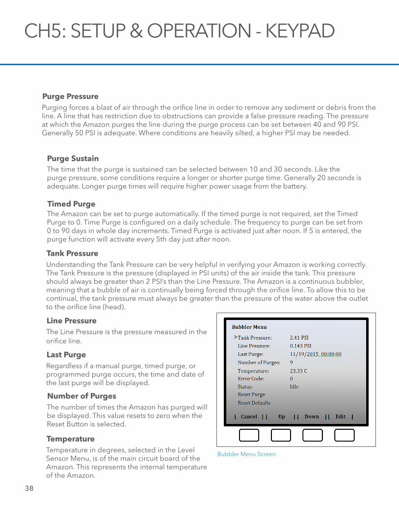
Tank PressureUnderstanding the Tank Pressure can be very helpful in verifying your Amazon is working correctly. The Tank Pressure is the pressure (displayed in PSI units) of the air inside the tank. This pressure should always be greater than 2 PSI’s than the Line Pressure. The Amazon is a continuous bubbler, meaning that a bubble of air is continually being forced through the orifice line. To allow this to be continual, the tank pressure must always be greater than the pressure of the water above the outlet to the orifice line (head).
Line PressureThe Line Pressure is the pressure measured in the orifice line.
Last PurgeRegardless if a manual purge, timed purge, or programmed purge occurs, the time and date of the last purge will be displayed.
Number of PurgesThe number of times the Amazon has purged will be displayed. This value resets to zero when the Reset Button is selected.
TemperatureTemperature in degrees, selected in the Level Sensor Menu, is of the main circuit board of the Amazon. This represents the internal temperature of the Amazon.
Bubbler Menu Screen
Timed PurgeThe Amazon can be set to purge automatically. If the timed purge is not required, set the Timed Purge to 0. Time Purge is configured on a daily schedule. The frequency to purge can be set from 0 to 90 days in whole day increments. Timed Purge is activated just after noon. If 5 is entered, the purge function will activate every 5th day just after noon.
The time that the purge is sustained can be selected between 10 and 30 seconds. Like the purge pressure, some conditions require a longer or shorter purge time. Generally 20 seconds is adequate. Longer purge times will require higher power usage from the battery.
Purge Sustain
Purge PressurePurging forces a blast of air through the orifice line in order to remove any sediment or debris from the line. A line that has restriction due to obstructions can provide a false pressure reading. The pressure at which the Amazon purges the line during the purge process can be set between 40 and 90 PSI. Generally 50 PSI is adequate. Where conditions are heavily silted, a higher PSI may be needed.
Ch5: Setup & Operation - Keypad
39
Error Code
The Amazon is continually monitoring its own functions and health. The numbers displayed represent an error code to determine which functions are not performing properly. In addition to the error code, a directive is provided on the Home Screen. There are four directive that may be posted: User Service, Factory Service, Call Support, Set Clock. You may be asked to provide this information if you should require technical assistance. Refer to Appendix B for an description of the error codes.
StatusThe Status provides the current state of the Amazon. In most situations this will display “Idle”. The text will change to “Measuring” during a measurement cycle and “Purging” during a purge cycle. You will also notice "Tank Maintenance" when the tank is being adjusted.
Reset DefaultsSelecting Reset Defaults will return all the bubbler configurations back to the factory defaults.
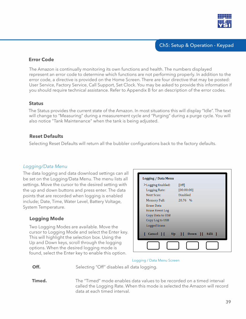
The data logging and data download settings can all be set on the Logging/Data Menu. The menu lists all settings. Move the cursor to the desired setting with the up and down buttons and press enter. The data points that are recorded when logging is enabled include; Date, Time, Water Level, Battery Voltage, System Temperature.
Logging/Data Menu
Logging / Data Menu Screen
Logging Mode
Two Logging Modes are available. Move the cursor to Logging Mode and select the Enter key. This will highlight the selection box. Using the Up and Down keys, scroll through the logging options. When the desired logging mode is found, select the Enter key to enable this option.
Timed. The “Timed” mode enables data values to be recorded on a timed interval called the Logging Rate. When this mode is selected the Amazon will record data at each timed interval.
Off. Selecting “Off” disables all data logging.
40
Logging RateThe rate at which data is recorded when Timed or Timed+External Logging Modes are enabled is entered in 24-hour notations (hh:mm:ss).
Next ScanThe Next Scan format is in a 24-hour notation (hh:mm:ss). This is the time when the next data will be recorded. If the Logging Mode is set to Off or External Only, then the Next Scan will be Disabled.
Memory Full %The Amazon provides 260 MB of memory. Under typical circumstances, this should provide enough memory to last for years. The units represented are the percentage of memory that has been used.
CH5: SETUP & OPERATION - KEYPAD
Erase Event LogRegardless of which Logging Mode that is being used, the Amazon records critical event data. This data includes critical information required by WaterLOG Technical Support to provide trouble shooting assistance. The event data can be cleared by selecting the Erase Event Log. Caution should be taken before selecting this button. All data should be downloaded first to a PC or USB Flash Drive before deleting the data from Event Log memory.
Copy Data to USBMeasurement data recorded in CSV format by the Amazon when the Timed, External Only, and Timed+External Logging Modes are enabled can be copied directly to a USB Flash Drive connected to the Amazon USB port. A USB Flash Drive must be connected to the Amazon before selecting the Copy Data to USB. With the USB Flash Drive connected, move the cursor to the Copy Data to USB and select the Enter button. A progress bar on the menu will indicate the memory is being copied. Once the data has been successfully copied, the word “Success” will be displayed. It is now safe to remove the USB Flash drive.
Erase Data
The entire memory of the Amazon can be clear by selecting the Erase Data button. Caution should be taken before selecting this button. All data should be downloaded first to a PC or USB Flash Drive before deleting the data from memory.
External Only. When External Logging Mode is enabled, the Amazon will record the measured data each time it receives an SDI-12 Command from a SDI-12 Recorder.
Timed+External. Both the Timed and External Logging Modes are enabled.
Ch5: Setup & Operation - Keypad
41
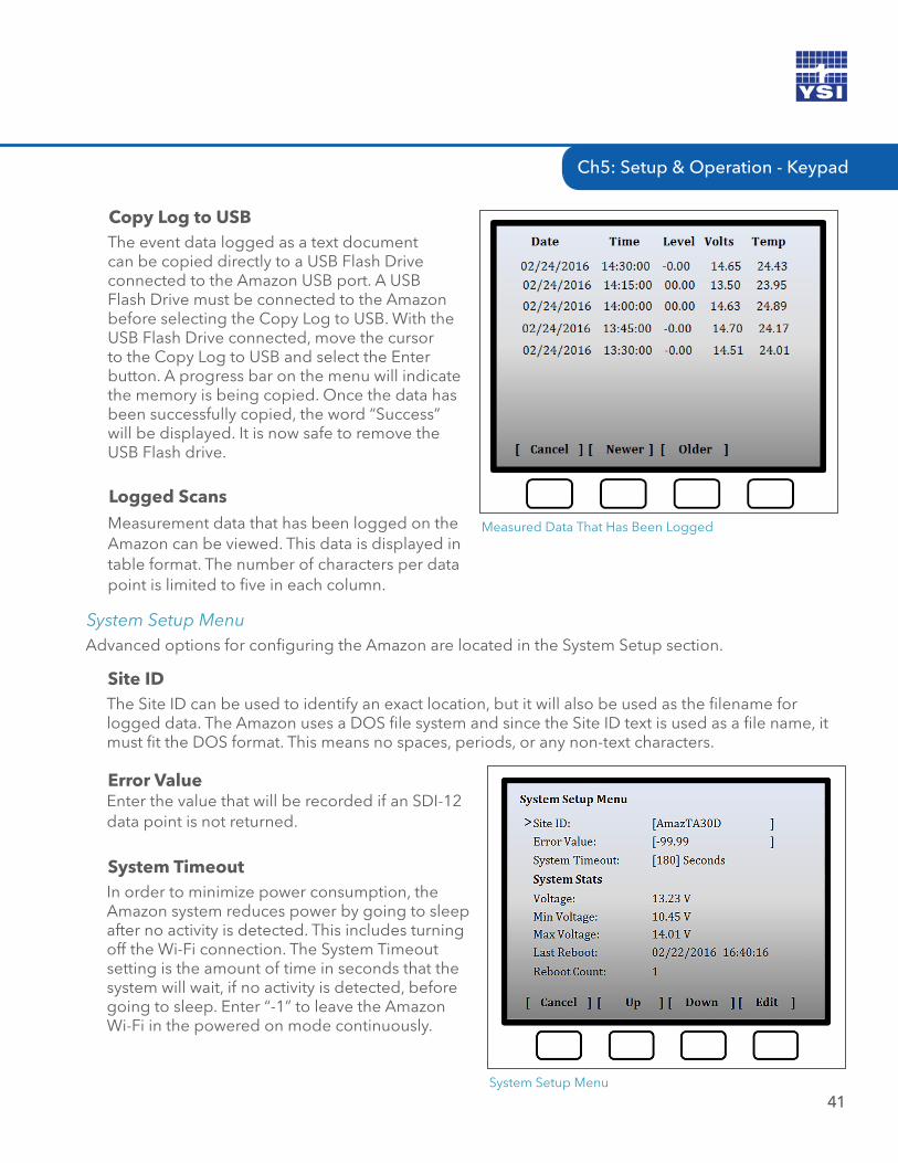
Copy Log to USBThe event data logged as a text document can be copied directly to a USB Flash Drive connected to the Amazon USB port. A USB Flash Drive must be connected to the Amazon before selecting the Copy Log to USB. With the USB Flash Drive connected, move the cursor to the Copy Log to USB and select the Enter button. A progress bar on the menu will indicate the memory is being copied. Once the data has been successfully copied, the word “Success” will be displayed. It is now safe to remove the USB Flash drive.
Measured Data That Has Been Logged
Logged ScansMeasurement data that has been logged on the Amazon can be viewed. This data is displayed in table format. The number of characters per data point is limited to five in each column.
Advanced options for configuring the Amazon are located in the System Setup section.
System Setup Menu
Site IDThe Site ID can be used to identify an exact location, but it will also be used as the filename for logged data. The Amazon uses a DOS file system and since the Site ID text is used as a file name, it must fit the DOS format. This means no spaces, periods, or any non-text characters.
Error ValueEnter the value that will be recorded if an SDI-12 data point is not returned.
System TimeoutIn order to minimize power consumption, the Amazon system reduces power by going to sleep after no activity is detected. This includes turning off the Wi-Fi connection. The System Timeout setting is the amount of time in seconds that the system will wait, if no activity is detected, before going to sleep. Enter “-1” to leave the Amazon Wi-Fi in the powered on mode continuously.
System Setup Menu
42
VoltageThe Amazon displays the current battery voltage from the systems +12 VDC input. Even though the battery voltage display will briefly rise and fall, the only voltage reading saved to your data will be at each logging interval.
Min VoltageEach time the Amazon measures the battery voltage it checks to see if the current voltage is less than the minimum value detected and then updates the minimum value if needed. This value is mainly provided as a diagnostic tool to help understand system performance and reliability. If the minimum voltage is too low it may indicate that the battery is being undercharged. See “Reset” below for more information.
Max VoltageEach time the Amazon measures the battery voltage it checks to see if the current voltage is greater than the maximum value detected and then updates the maximum value if needed. A high value may indicate a faulty regulator. See “Reset” below for more information.
CH5: SETUP & OPERATION - KEYPAD
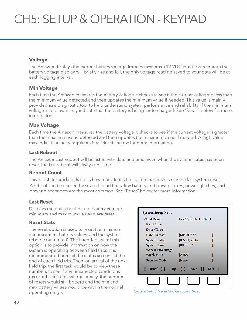
Last RebootThe Amazon Last Reboot will be listed with date and time. Even when the system status has been reset, the last reboot will always be listed.
Reboot CountThis is a status update that lists how many times the system has reset since the last system reset.
Last ResetDisplays the date and time the battery voltage minimum and maximum values were reset.
System Setup Menu Showing Last Reset
Reset StatsThe reset option is used to reset the minimum and maximum battery values, and the system reboot counter to 0. The intended use of this option is to provide information on how the system is operating between field trips. It is recommended to reset the status screens at the end of each field trip. Then, on arrival of the next field trip, the first task would be to view these numbers to see if any unexpected conditions occurred since the last trip. Ideally, the number of resets would still be zero and the min and max battery values would be within the normal operating range.
A reboot can be caused by several conditions, low battery and power spikes, power glitches, and power disconnects are the most common. See “Reset” below for more information.
Ch5: Setup & Operation - Keypad
43
Date FormatSelect the desired date format that the Amazon will use to display the date stamp and record the date stamp.
System Date
Edit the current Date on the Amazon. The date format can be changed in the Date Format selection field.
System TimeEdit the current Date on the Amazon.
Wireless IDWhen using the Wi-Fi connection of the Amazon, the device is recognized on the Network by its Wireless ID. Create the Wireless ID by moving to the cursor to the Wireless ID then selecting the Enter key. Now use the Up, Down, Right and Left keys to select the desired characters. When finished, use the Right key until the cursor is out of the edit box.
Security ModeThe Amazon provides a security gate into the functionality of the system. Selecting WPA2, WPA, WPA + WPA2 must be consistent with your modem or router settings.
Pass PhraseEntered the desired Pass Phrase to limit entry through the Wi-Fi connection. Once a pass phrase has been selected, it will be required on the smart phone, tablet, or PC. WPA specs require the pass phrase to be between 8 and 63 printable characters.
Restore DefaultsThe original factory default settings can be restored by selecting Restore Defaults.
Save ConfigurationOnce the configuration of the Amazon has been set, these setting can be saved. This configuration is saved to the memory of the Amazon.
Save USB ConfigurationOnce the Amazon configuration has been set, this file can be loaded onto a USB Flash Drive.
Load USB ConfigurationYou must choose a configuration file from the USB before you can load a configuration. The configuration that has been saved onto a USB Flash Drive can be retrieved and loaded onto the Amazon.
Load ConfigurationThe configuration that has been saved on the Amazon can be loaded back onto the Amazon.
44
FileSelecting file provides a list of available firmware files saved on the attached USB Flash Drive. Insert the USB Flash Drive then scroll through the available files using the up and down buttons.
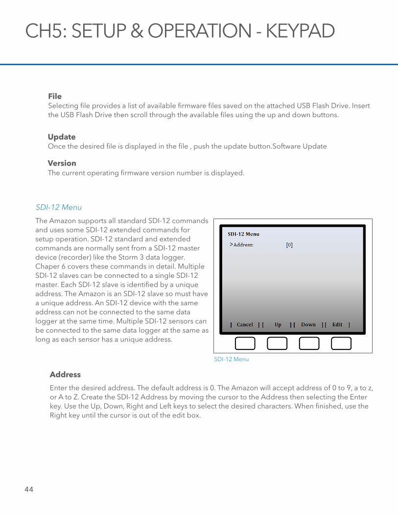
The Amazon supports all standard SDI-12 commands and uses some SDI-12 extended commands for setup operation. SDI-12 standard and extended commands are normally sent from a SDI-12 master device (recorder) like the Storm 3 data logger. Chaper 6 covers these commands in detail. Multiple SDI-12 slaves can be connected to a single SDI-12 master. Each SDI-12 slave is identified by a unique address. The Amazon is an SDI-12 slave so must have a unique address. An SDI-12 device with the same address can not be connected to the same data logger at the same time. Multiple SDI-12 sensors can be connected to the same data logger at the same as long as each sensor has a unique address.
SDI-12 Menu
SDI-12 Menu
CH5: SETUP & OPERATION - KEYPAD
UpdateOnce the desired file is displayed in the file , push the update button.Software Update
VersionThe current operating firmware version number is displayed.
Address
Enter the desired address. The default address is 0. The Amazon will accept address of 0 to 9, a to z, or A to Z. Create the SDI-12 Address by moving the cursor to the Address then selecting the Enter key. Use the Up, Down, Right and Left keys to select the desired characters. When finished, use the Right key until the cursor is out of the edit box.
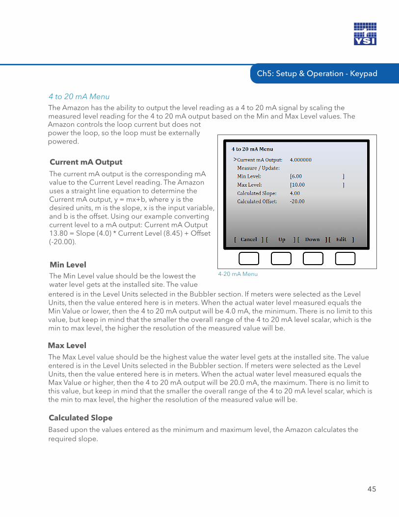
Ch5: Setup & Operation - Keypad
45
Current mA OutputThe current mA output is the corresponding mA value to the Current Level reading. The Amazon uses a straight line equation to determine the Current mA output, y = mx+b, where y is the desired units, m is the slope, x is the input variable, and b is the offset. Using our example converting current level to a mA output: Current mA Output 13.80 = Slope (4.0) * Current Level (8.45) + Offset (-20.00).
Min LevelThe Min Level value should be the lowest the water level gets at the installed site. The value
4-20 mA Menu
Max LevelThe Max Level value should be the highest value the water level gets at the installed site. The value entered is in the Level Units selected in the Bubbler section. If meters were selected as the Level Units, then the value entered here is in meters. When the actual water level measured equals the Max Value or higher, then the 4 to 20 mA output will be 20.0 mA, the maximum. There is no limit to this value, but keep in mind that the smaller the overall range of the 4 to 20 mA level scalar, which is the min to max level, the higher the resolution of the measured value will be.
The Amazon has the ability to output the level reading as a 4 to 20 mA signal by scaling the measured level reading for the 4 to 20 mA output based on the Min and Max Level values. The
4 to 20 mA Menu
entered is in the Level Units selected in the Bubbler section. If meters were selected as the Level Units, then the value entered here is in meters. When the actual water level measured equals the Min Value or lower, then the 4 to 20 mA output will be 4.0 mA, the minimum. There is no limit to this value, but keep in mind that the smaller the overall range of the 4 to 20 mA level scalar, which is the min to max level, the higher the resolution of the measured value will be.
Calculated SlopeBased upon the values entered as the minimum and maximum level, the Amazon calculates the required slope.
Amazon controls the loop current but does not power the loop, so the loop must be externally powered.
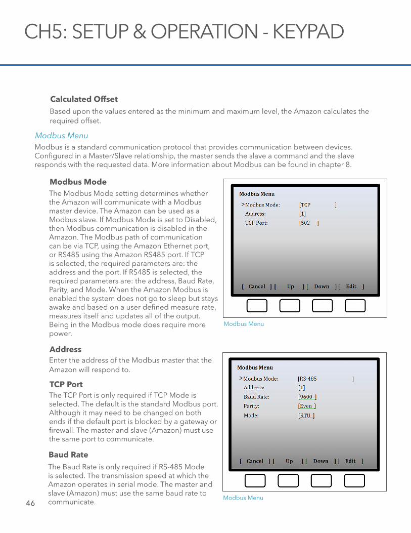
46
Modbus ModeThe Modbus Mode setting determines whether the Amazon will communicate with a Modbus master device. The Amazon can be used as a Modbus slave. If Modbus Mode is set to Disabled, then Modbus communication is disabled in the Amazon. The Modbus path of communication can be via TCP, using the Amazon Ethernet port, or RS485 using the Amazon RS485 port. If TCP is selected, the required parameters are: the address and the port. If RS485 is selected, the required parameters are: the address, Baud Rate, Parity, and Mode. When the Amazon Modbus is enabled the system does not go to sleep but stays awake and based on a user defined measure rate, measures itself and updates all of the output. Being in the Modbus mode does require more power.
Modbus Menu
AddressEnter the address of the Modbus master that the Amazon will respond to.
Modbus Menu
TCP PortThe TCP Port is only required if TCP Mode is selected. The default is the standard Modbus port. Although it may need to be changed on both ends if the default port is blocked by a gateway or firewall. The master and slave (Amazon) must use the same port to communicate.
Baud RateThe Baud Rate is only required if RS-485 Mode is selected. The transmission speed at which the Amazon operates in serial mode. The master and slave (Amazon) must use the same baud rate to communicate.
CH5: SETUP & OPERATION - KEYPAD
Modbus is a standard communication protocol that provides communication between devices. Configured in a Master/Slave relationship, the master sends the slave a command and the slave responds with the requested data. More information about Modbus can be found in chapter 8.
Modbus Menu
Calculated OffsetBased upon the values entered as the minimum and maximum level, the Amazon calculates the required offset.
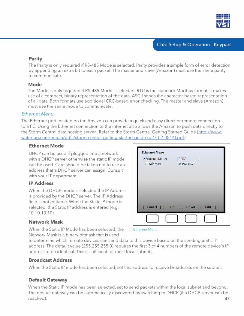
Ch5: Setup & Operation - Keypad
ParityThe Parity is only required if RS-485 Mode is selected. Parity provides a simple form of error detection by appending an extra bit to each packet. The master and slave (Amazon) must use the same parity to communicate.
ModeThe Mode is only required if RS-485 Mode is selected. RTU is the standard Modbus format. It makes use of a compact, binary representation of the data. ASCII sends the character-based representation of all data. Both formats use additional CRC-based error checking. The master and slave (Amazon) must use the same mode to communicate.
47
The Ethernet port located on the Amazon can provide a quick and easy direct or remote connection to a PC. Using the Ethernet connection to the internet also allows the Amazon to push data directly to the Storm Central data hosting server. Refer to the Storm Central Getting Started Guide (http://www.waterlog.com/media/pdfs/storm-central-getting-started-guide-(d27-02-0514).pdf)
Ethernet Menu
Ethernet Menu
Ethernet Mode
DHCP can be used if plugged into a network with a DHCP server otherwise the static IP mode can be used. Care should be taken not to use an address that a DHCP server can assign. Consult with your IT department.
IP AddressWhen the DHCP mode is selected the IP Address is provided by the DHCP server. The IP Address field is not editable. When the Static IP mode is selected, the Static IP address is entered (e.g. 10.10.10.10)
Network MaskWhen the Static IP Mode has been selected, the Network Mask is a binary bitmask that is used
Broadcast AddressWhen the Static IP mode has been selected, set this address to receive broadcasts on the subnet.
to determine which remote devices can send data to this device based on the sending unit's IP address. The default value (255.255.255.0) requires the first 3 of 4 numbers of the remote device's IP address to be identical. This is sufficient for most local subnets.
Default GatewayWhen the Static IP mode has been selected, set to send packets within the local subnet and beyond. The default gateway can be automatically discovered by switching to DHCP (if a DHCP server can be reached).
48
06 / SDI-12 INTERFACE
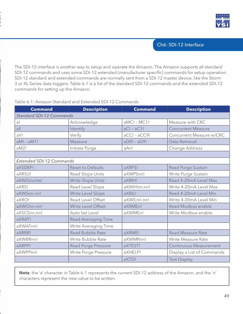
49
The SDI-12 interface is another way to setup and operate the Amazon. The Amazon supports all standard SDI-12 commands and uses some SDI-12 extended (manufacturer specific) commands for setup operation. SDI-12 standard and extended commands are normally sent from a SDI-12 master device, like the Storm 3 or XL Series data loggers. Table 6-1 is a list of the standard SDI-12 commands and the extended SDI-12 commands for setting up the Amazon.
Command Description Command DescriptionStandard SDI-12 Commandsa! Acknowledge aMC! – MC1! Measure with CRCaI! Identify aC! – aC1! Concurrent MeasureaV! Verify aCC! – aCC9! Concurrent Measure w/CRCaM! – aM1! Measure aD0! – aD9! Data RetrievalaM2! Initiate Purge aAn! Change Address
Extended SDI-12 CommandsaXSDEF! Reset to Defaults aXRPS! Read Purge SustainaXRSU! Read Slope Units aXWPSnn! Write Purge SustainaXWSUunits! Write Slope Units aXRIH! Read 4-20mA Level MaxaXRS! Read Level Slope aXWIHnn.nn! Write 4-20mA Level MaxaXWSnn.nn! Write Level Slope aXRIL! Read 4-20mA Level MinaXRO! Read Level Offset aXWILnn.nn! Write 4-20mA Level MinaXWOnn.nn! Write Level Offset aXRMEn! Read Modbus enableaXSCSnn.nn! Auto Set Level aXWMEn! Write Modbus enableaXRAT! Read Averaging Time
aXWATnn! Write Averaging Time
aXRBR! Read Bubble Rate aXRME! Read Measure RateaXWBRnn! Write Bubble Rate aXWMRnn! Write Measure RateaXRPP! Read Purge Pressure aXTEST! Continuous MeasurementaXWPPnn! Write Purge Pressure aXHELP! Display a List of Commands
aXTD! Test Display
Table 6-1: Amazon Standard and Extended SDI-12 Commands
Note, the ‘a’ character in Table 6-1 represents the current SDI-12 address of the Amazon, and the ‘n’ characters represent the new value to be written.
Ch6: SDI-12 Interface
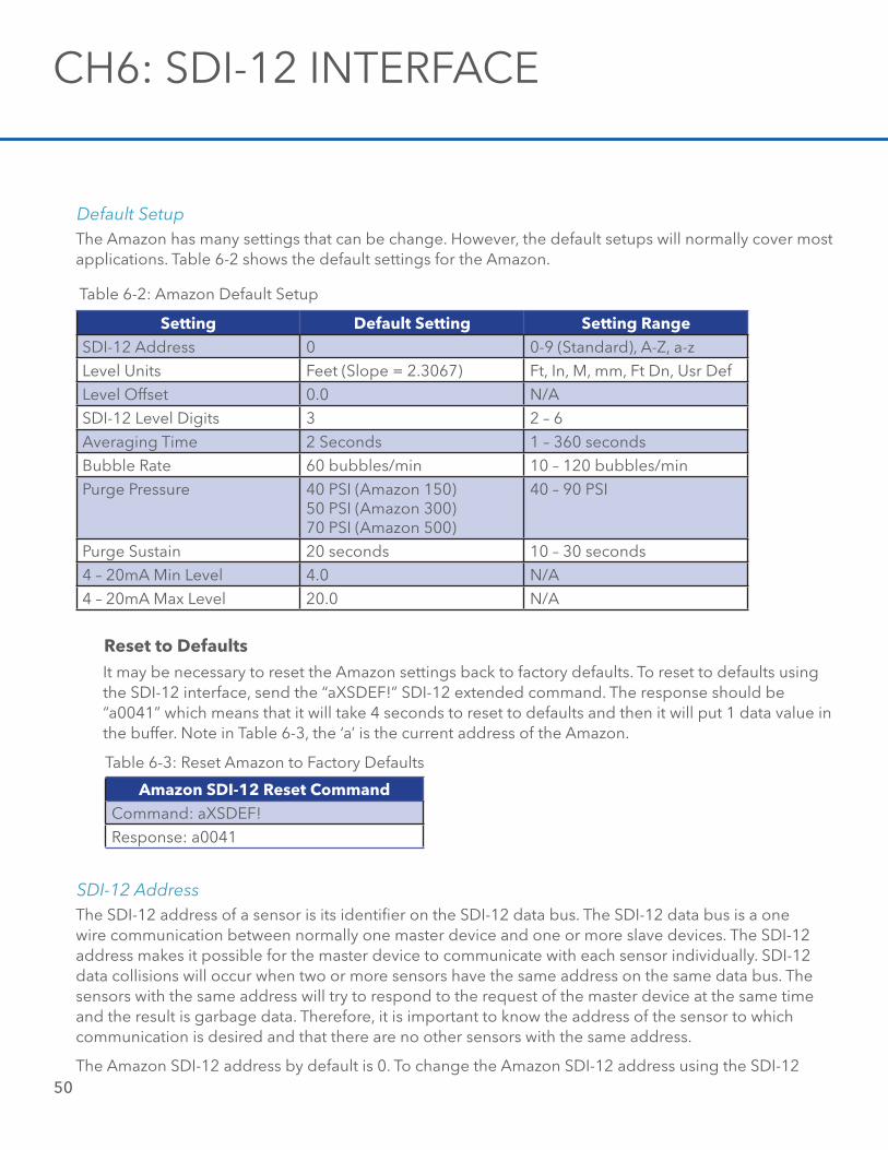
50
The Amazon has many settings that can be change. However, the default setups will normally cover most applications. Table 6-2 shows the default settings for the Amazon.
Default Setup
Setting Default Setting Setting RangeSDI-12 Address 0 0-9 (Standard), A-Z, a-zLevel Units Feet (Slope = 2.3067) Ft, In, M, mm, Ft Dn, Usr DefLevel Offset 0.0 N/ASDI-12 Level Digits 3 2 – 6 Averaging Time 2 Seconds 1 – 360 secondsBubble Rate 60 bubbles/min 10 – 120 bubbles/minPurge Pressure 40 PSI (Amazon 150)
50 PSI (Amazon 300)70 PSI (Amazon 500)
40 – 90 PSI
Purge Sustain 20 seconds 10 – 30 seconds4 – 20mA Min Level 4.0 N/A4 – 20mA Max Level 20.0 N/A
Table 6-2: Amazon Default Setup
Reset to DefaultsIt may be necessary to reset the Amazon settings back to factory defaults. To reset to defaults using the SDI-12 interface, send the “aXSDEF!” SDI-12 extended command. The response should be “a0041” which means that it will take 4 seconds to reset to defaults and then it will put 1 data value in the buffer. Note in Table 6-3, the ‘a’ is the current address of the Amazon.
Amazon SDI-12 Reset CommandCommand: aXSDEF!Response: a0041
Table 6-3: Reset Amazon to Factory Defaults
The SDI-12 address of a sensor is its identifier on the SDI-12 data bus. The SDI-12 data bus is a one wire communication between normally one master device and one or more slave devices. The SDI-12 address makes it possible for the master device to communicate with each sensor individually. SDI-12 data collisions will occur when two or more sensors have the same address on the same data bus. The sensors with the same address will try to respond to the request of the master device at the same time and the result is garbage data. Therefore, it is important to know the address of the sensor to which communication is desired and that there are no other sensors with the same address.
The Amazon SDI-12 address by default is 0. To change the Amazon SDI-12 address using the SDI-12
SDI-12 Address
CH6: SDI-12 INTERFACE
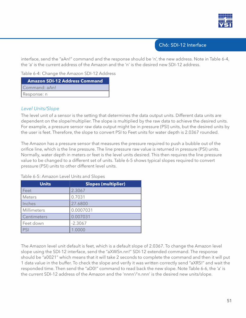
Ch6: SDI-12 Interface
51
interface, send the “aAn!” command and the response should be ‘n’, the new address. Note in Table 6-4, the ‘a’ is the current address of the Amazon and the ‘n’ is the desired new SDI-12 address.
Amazon SDI-12 Address CommandCommand: aAn!Response: n
Table 6-4: Change the Amazon SDI-12 Address
The level unit of a sensor is the setting that determines the data output units. Different data units are dependent on the slope/multiplier. The slope is multiplied by the raw data to achieve the desired units. For example, a pressure sensor raw data output might be in pressure (PSI) units, but the desired units by the user is feet. Therefore, the slope to convert PSI to Feet units for water depth is 2.0367 rounded.
The Amazon has a pressure sensor that measures the pressure required to push a bubble out of the orifice line, which is the line pressure. The line pressure raw value is returned in pressure (PSI) units. Normally, water depth in meters or feet is the level units desired. This then requires the line pressure value to be changed to a different set of units. Table 6-5 shows typical slopes required to convert pressure (PSI) units to other different level units.
Level Units/Slope
Units Slopes (multiplier)Feet 2.3067Meters 0.7031Inches 27.6800Millimeters 0.0007031Centimeters 0.007031Feet down -2.3067PSI 1.0000
Table 6-5: Amazon Level Units and Slopes
The Amazon level unit default is feet, which is a default slope of 2.0367. To change the Amazon level slope using the SDI-12 interface, send the “aXWSn.nn!” SDI-12 extended command. The response should be “a0021” which means that it will take 2 seconds to complete the command and then it will put 1 data value in the buffer. To check the slope and verify it was written correctly send “aXRS!” and wait the responded time. Then send the “aD0!” command to read back the new slope. Note Table 6-6, the ‘a’ is the current SDI-12 address of the Amazon and the ‘nnnn’/’n.nnn’ is the desired new units/slope.
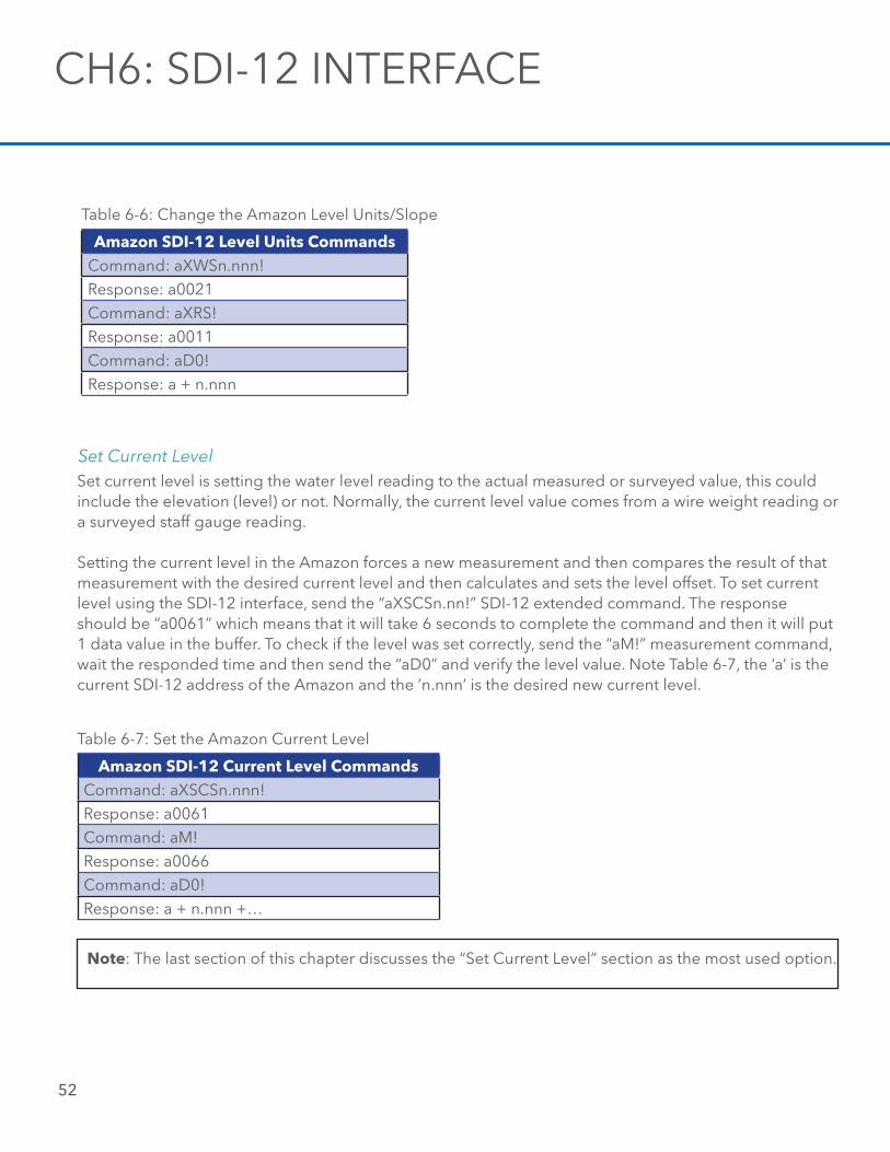
52
Amazon SDI-12 Level Units CommandsCommand: aXWSn.nnn!Response: a0021Command: aXRS!Response: a0011Command: aD0!Response: a + n.nnn
Table 6-6: Change the Amazon Level Units/Slope
Set current level is setting the water level reading to the actual measured or surveyed value, this could include the elevation (level) or not. Normally, the current level value comes from a wire weight reading or a surveyed staff gauge reading. Setting the current level in the Amazon forces a new measurement and then compares the result of that measurement with the desired current level and then calculates and sets the level offset. To set current level using the SDI-12 interface, send the “aXSCSn.nn!” SDI-12 extended command. The response should be “a0061” which means that it will take 6 seconds to complete the command and then it will put 1 data value in the buffer. To check if the level was set correctly, send the “aM!” measurement command, wait the responded time and then send the “aD0” and verify the level value. Note Table 6-7, the ‘a’ is the current SDI-12 address of the Amazon and the ’n.nnn’ is the desired new current level.
Set Current Level
Amazon SDI-12 Current Level CommandsCommand: aXSCSn.nnn!Response: a0061Command: aM!Response: a0066Command: aD0!Response: a + n.nnn +…
Table 6-7: Set the Amazon Current Level
Note: The last section of this chapter discusses the “Set Current Level” section as the most used option.
CH6: SDI-12 INTERFACE
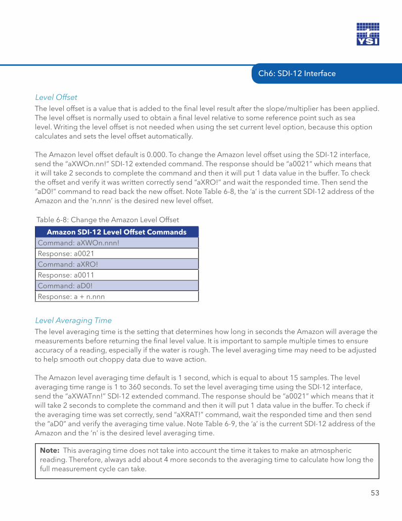
Ch6: SDI-12 Interface
The level offset is a value that is added to the final level result after the slope/multiplier has been applied. The level offset is normally used to obtain a final level relative to some reference point such as sea level. Writing the level offset is not needed when using the set current level option, because this option calculates and sets the level offset automatically. The Amazon level offset default is 0.000. To change the Amazon level offset using the SDI-12 interface, send the “aXWOn.nn!” SDI-12 extended command. The response should be “a0021” which means that it will take 2 seconds to complete the command and then it will put 1 data value in the buffer. To check the offset and verify it was written correctly send “aXRO!” and wait the responded time. Then send the “aD0!” command to read back the new offset. Note Table 6-8, the ‘a’ is the current SDI-12 address of the Amazon and the ’n.nnn’ is the desired new level offset.
Level Offset
53
Amazon SDI-12 Level Offset CommandsCommand: aXWOn.nnn!Response: a0021Command: aXRO!Response: a0011Command: aD0!Response: a + n.nnn
Table 6-8: Change the Amazon Level Offset
The level averaging time is the setting that determines how long in seconds the Amazon will average the measurements before returning the final level value. It is important to sample multiple times to ensure accuracy of a reading, especially if the water is rough. The level averaging time may need to be adjusted to help smooth out choppy data due to wave action.
The Amazon level averaging time default is 1 second, which is equal to about 15 samples. The level averaging time range is 1 to 360 seconds. To set the level averaging time using the SDI-12 interface, send the “aXWATnn!” SDI-12 extended command. The response should be “a0021” which means that it will take 2 seconds to complete the command and then it will put 1 data value in the buffer. To check if the averaging time was set correctly, send “aXRAT!” command, wait the responded time and then send the “aD0” and verify the averaging time value. Note Table 6-9, the ‘a’ is the current SDI-12 address of the Amazon and the ‘n’ is the desired level averaging time.
Level Averaging Time
Note: This averaging time does not take into account the time it takes to make an atmospheric reading. Therefore, always add about 4 more seconds to the averaging time to calculate how long the full measurement cycle can take.
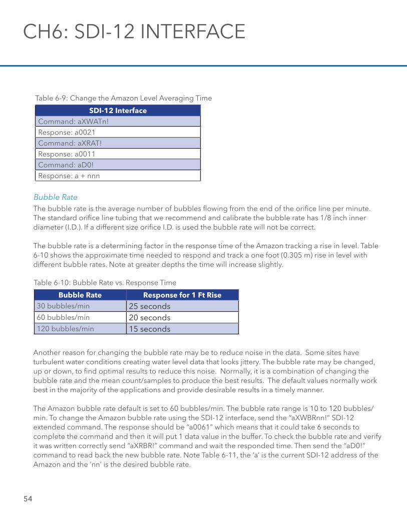
54
SDI-12 InterfaceCommand: aXWATn!Response: a0021Command: aXRAT!Response: a0011Command: aD0!Response: a + nnn
Table 6-9: Change the Amazon Level Averaging Time
The bubble rate is the average number of bubbles flowing from the end of the orifice line per minute. The standard orifice line tubing that we recommend and calibrate the bubble rate has 1/8 inch inner diameter (I.D.). If a different size orifice I.D. is used the bubble rate will not be correct.
The bubble rate is a determining factor in the response time of the Amazon tracking a rise in level. Table 6-10 shows the approximate time needed to respond and track a one foot (0.305 m) rise in level with different bubble rates. Note at greater depths the time will increase slightly.
Bubble Rate
Bubble Rate Response for 1 Ft Rise30 bubbles/min 25 seconds60 bubbles/min 20 seconds120 bubbles/min 15 seconds
Table 6-10: Bubble Rate vs. Response Time
Another reason for changing the bubble rate may be to reduce noise in the data. Some sites have turbulent water conditions creating water level data that looks jittery. The bubble rate may be changed, up or down, to find optimal results to reduce this noise. Normally, it is a combination of changing the bubble rate and the mean count/samples to produce the best results. The default values normally work best in the majority of the applications and provide desirable results in a timely manner. The Amazon bubble rate default is set to 60 bubbles/min. The bubble rate range is 10 to 120 bubbles/min. To change the Amazon bubble rate using the SDI-12 interface, send the “aXWBRnn!” SDI-12 extended command. The response should be “a0061” which means that it could take 6 seconds to complete the command and then it will put 1 data value in the buffer. To check the bubble rate and verify it was written correctly send “aXRBR!” command and wait the responded time. Then send the “aD0!” command to read back the new bubble rate. Note Table 6-11, the ‘a’ is the current SDI-12 address of the Amazon and the ‘nn’ is the desired bubble rate.
CH6: SDI-12 INTERFACE
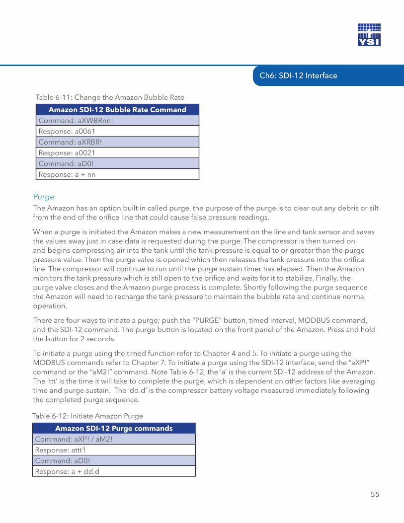
Ch6: SDI-12 Interface
55
Amazon SDI-12 Bubble Rate CommandCommand: aXWBRnn!Response: a0061Command: aXRBR!Response: a0021Command: aD0!Response: a + nn
Table 6-11: Change the Amazon Bubble Rate
The Amazon has an option built in called purge, the purpose of the purge is to clear out any debris or silt from the end of the orifice line that could cause false pressure readings.
When a purge is initiated the Amazon makes a new measurement on the line and tank sensor and saves the values away just in case data is requested during the purge. The compressor is then turned on and begins compressing air into the tank until the tank pressure is equal to or greater than the purge pressure value. Then the purge valve is opened which then releases the tank pressure into the orifice line. The compressor will continue to run until the purge sustain timer has elapsed. Then the Amazon monitors the tank pressure which is still open to the orifice and waits for it to stabilize. Finally, the purge valve closes and the Amazon purge process is complete. Shortly following the purge sequence the Amazon will need to recharge the tank pressure to maintain the bubble rate and continue normal operation.
There are four ways to initiate a purge; push the “PURGE” button, timed interval, MODBUS command, and the SDI-12 command. The purge button is located on the front panel of the Amazon. Press and hold the button for 2 seconds.
To initiate a purge using the timed function refer to Chapter 4 and 5. To initiate a purge using the MODBUS commands refer to Chapter 7. To initiate a purge using the SDI-12 interface, send the “aXP!” command or the “aM2!” command. Note Table 6-12, the ‘a’ is the current SDI-12 address of the Amazon. The ‘ttt’ is the time it will take to complete the purge, which is dependent on other factors like averaging time and purge sustain. The ‘dd.d’ is the compressor battery voltage measured immediately following the completed purge sequence.
Purge
Amazon SDI-12 Purge commandsCommand: aXP! / aM2!Response: attt1Command: aD0!Response: a + dd.d
Table 6-12: Initiate Amazon Purge
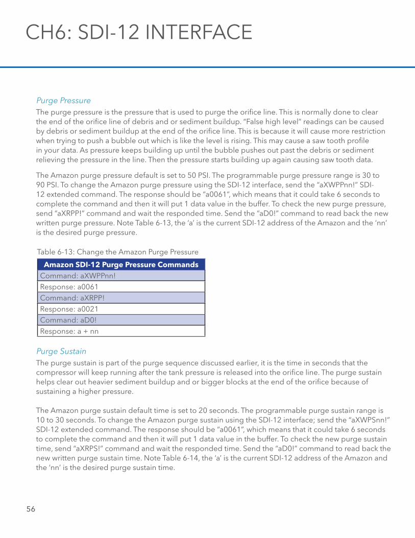
56
The purge pressure is the pressure that is used to purge the orifice line. This is normally done to clear the end of the orifice line of debris and or sediment buildup. “False high level” readings can be caused by debris or sediment buildup at the end of the orifice line. This is because it will cause more restriction when trying to push a bubble out which is like the level is rising. This may cause a saw tooth profile in your data. As pressure keeps building up until the bubble pushes out past the debris or sediment relieving the pressure in the line. Then the pressure starts building up again causing saw tooth data. The Amazon purge pressure default is set to 50 PSI. The programmable purge pressure range is 30 to 90 PSI. To change the Amazon purge pressure using the SDI-12 interface, send the “aXWPPnn!” SDI-12 extended command. The response should be “a0061”, which means that it could take 6 seconds to complete the command and then it will put 1 data value in the buffer. To check the new purge pressure, send “aXRPP!” command and wait the responded time. Send the “aD0!” command to read back the new written purge pressure. Note Table 6-13, the ‘a’ is the current SDI-12 address of the Amazon and the ‘nn’ is the desired purge pressure.
Purge Pressure
Amazon SDI-12 Purge Pressure CommandsCommand: aXWPPnn!Response: a0061Command: aXRPP!Response: a0021Command: aD0!Response: a + nn
Table 6-13: Change the Amazon Purge Pressure
The purge sustain is part of the purge sequence discussed earlier, it is the time in seconds that the compressor will keep running after the tank pressure is released into the orifice line. The purge sustain helps clear out heavier sediment buildup and or bigger blocks at the end of the orifice because of sustaining a higher pressure.
The Amazon purge sustain default time is set to 20 seconds. The programmable purge sustain range is 10 to 30 seconds. To change the Amazon purge sustain using the SDI-12 interface; send the “aXWPSnn!” SDI-12 extended command. The response should be “a0061”, which means that it could take 6 seconds to complete the command and then it will put 1 data value in the buffer. To check the new purge sustain time, send “aXRPS!” command and wait the responded time. Send the “aD0!” command to read back the new written purge sustain time. Note Table 6-14, the ‘a’ is the current SDI-12 address of the Amazon and the ‘nn’ is the desired purge sustain time.
Purge Sustain
CH6: SDI-12 INTERFACE
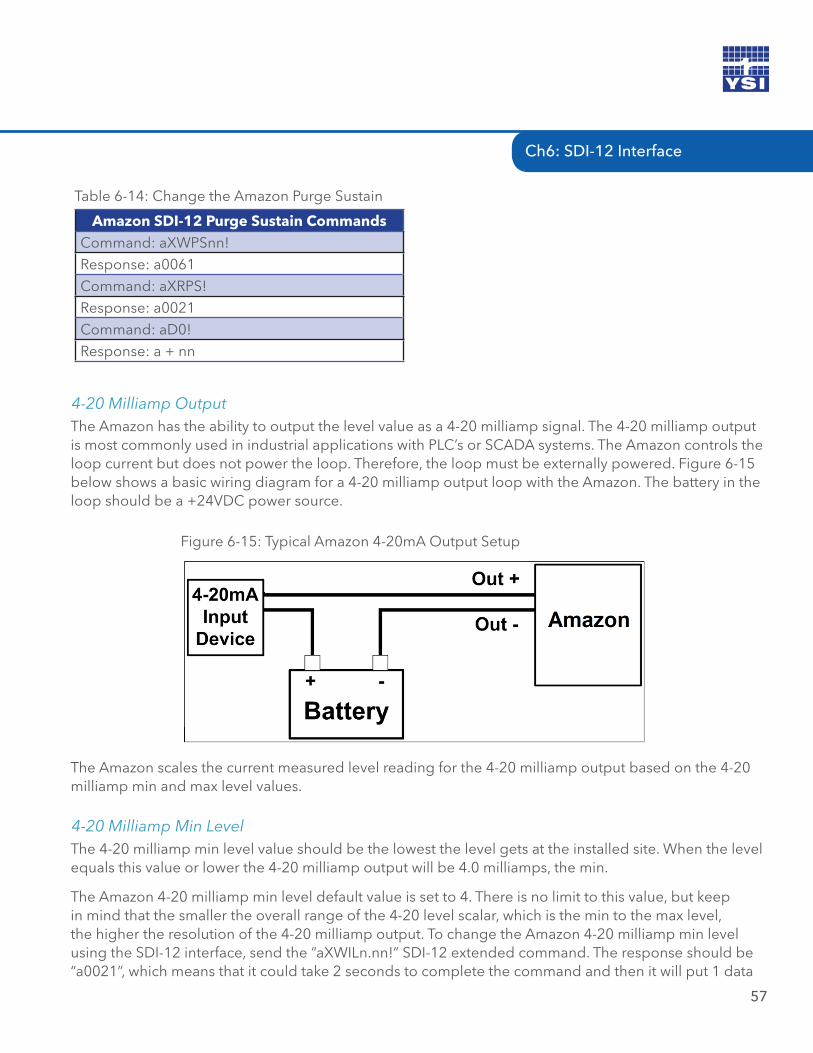
Ch6: SDI-12 Interface
57
Amazon SDI-12 Purge Sustain CommandsCommand: aXWPSnn!Response: a0061Command: aXRPS!Response: a0021Command: aD0!Response: a + nn
Table 6-14: Change the Amazon Purge Sustain
The Amazon has the ability to output the level value as a 4-20 milliamp signal. The 4-20 milliamp output is most commonly used in industrial applications with PLC’s or SCADA systems. The Amazon controls the loop current but does not power the loop. Therefore, the loop must be externally powered. Figure 6-15 below shows a basic wiring diagram for a 4-20 milliamp output loop with the Amazon. The battery in the loop should be a +24VDC power source.
4-20 Milliamp Output
Figure 6-15: Typical Amazon 4-20mA Output Setup
The Amazon scales the current measured level reading for the 4-20 milliamp output based on the 4-20 milliamp min and max level values.
The 4-20 milliamp min level value should be the lowest the level gets at the installed site. When the level equals this value or lower the 4-20 milliamp output will be 4.0 milliamps, the min.
The Amazon 4-20 milliamp min level default value is set to 4. There is no limit to this value, but keep in mind that the smaller the overall range of the 4-20 level scalar, which is the min to the max level, the higher the resolution of the 4-20 milliamp output. To change the Amazon 4-20 milliamp min level using the SDI-12 interface, send the “aXWILn.nn!” SDI-12 extended command. The response should be “a0021”, which means that it could take 2 seconds to complete the command and then it will put 1 data
4-20 Milliamp Min Level
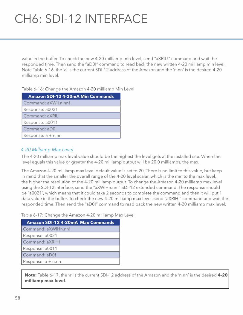
58
value in the buffer. To check the new 4-20 milliamp min level, send “aXRIL!” command and wait the responded time. Then send the “aD0!” command to read back the new written 4-20 milliamp min level. Note Table 6-16, the ‘a’ is the current SDI-12 address of the Amazon and the ‘n.nn’ is the desired 4-20 milliamp min level.
Amazon SDI-12 4-20mA Min CommandsCommand: aXWILn.nn!Response: a0021Command: aXRIL!Response: a0011Command: aD0!Response: a + n.nn
Table 6-16: Change the Amazon 4-20 milliamp Min Level
The 4-20 milliamp max level value should be the highest the level gets at the installed site. When the level equals this value or greater the 4-20 milliamp output will be 20.0 milliamps, the max.
The Amazon 4-20 milliamp max level default value is set to 20. There is no limit to this value, but keep in mind that the smaller the overall range of the 4-20 level scalar, which is the min to the max level, the higher the resolution of the 4-20 milliamp output. To change the Amazon 4-20 milliamp max level using the SDI-12 interface, send the “aXWIHn.nn!” SDI-12 extended command. The response should be “a0021”, which means that it could take 2 seconds to complete the command and then it will put 1 data value in the buffer. To check the new 4-20 milliamp max level, send “aXRIH!” command and wait the responded time. Then send the “aD0!” command to read back the new written 4-20 milliamp max level.
4-20 Milliamp Max Level
Amazon SDI-12 4-20mA Max CommandsCommand: aXWIHn.nn!Response: a0021Command: aXRIH!Response: a0011Command: aD0!Response: a + n.nn
Table 6-17: Change the Amazon 4-20 milliamp Max Level
CH6: SDI-12 INTERFACE
Note: Table 6-17, the ‘a’ is the current SDI-12 address of the Amazon and the ‘n.nn’ is the desired 4-20 milliamp max level.
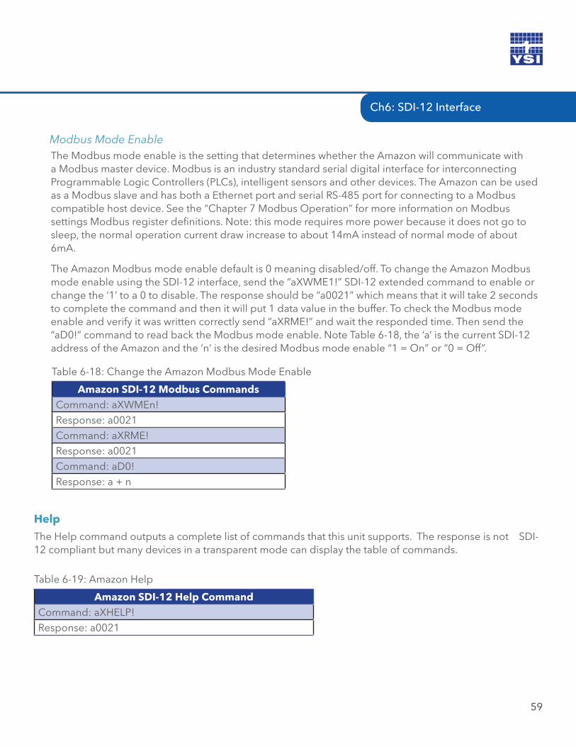
Ch6: SDI-12 Interface
59
The Modbus mode enable is the setting that determines whether the Amazon will communicate with a Modbus master device. Modbus is an industry standard serial digital interface for interconnecting Programmable Logic Controllers (PLCs), intelligent sensors and other devices. The Amazon can be used as a Modbus slave and has both a Ethernet port and serial RS-485 port for connecting to a Modbus compatible host device. See the “Chapter 7 Modbus Operation” for more information on Modbus settings Modbus register definitions. Note: this mode requires more power because it does not go to sleep, the normal operation current draw increase to about 14mA instead of normal mode of about 6mA.
The Amazon Modbus mode enable default is 0 meaning disabled/off. To change the Amazon Modbus mode enable using the SDI-12 interface, send the “aXWME1!” SDI-12 extended command to enable or change the ‘1’ to a 0 to disable. The response should be “a0021” which means that it will take 2 seconds to complete the command and then it will put 1 data value in the buffer. To check the Modbus mode enable and verify it was written correctly send “aXRME!” and wait the responded time. Then send the “aD0!” command to read back the Modbus mode enable. Note Table 6-18, the ‘a’ is the current SDI-12 address of the Amazon and the ‘n’ is the desired Modbus mode enable “1 = On” or “0 = Off”.
Modbus Mode Enable
Amazon SDI-12 Modbus CommandsCommand: aXWMEn!Response: a0021Command: aXRME!Response: a0021Command: aD0!Response: a + n
Table 6-18: Change the Amazon Modbus Mode Enable
Help
The Help command outputs a complete list of commands that this unit supports. The response is not SDI-12 compliant but many devices in a transparent mode can display the table of commands.
Amazon SDI-12 Help CommandCommand: aXHELP!Response: a0021
Table 6-19: Amazon Help
60
07 / MODBUS OPERATION
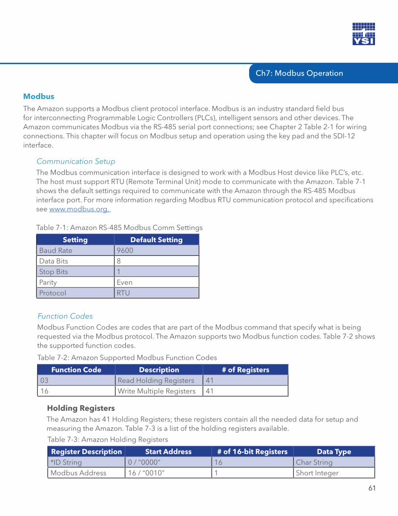
61
Modbus
The Amazon supports a Modbus client protocol interface. Modbus is an industry standard field bus for interconnecting Programmable Logic Controllers (PLCs), intelligent sensors and other devices. The Amazon communicates Modbus via the RS-485 serial port connections; see Chapter 2 Table 2-1 for wiring connections. This chapter will focus on Modbus setup and operation using the key pad and the SDI-12 interface.
The Modbus communication interface is designed to work with a Modbus Host device like PLC’s, etc. The host must support RTU (Remote Terminal Unit) mode to communicate with the Amazon. Table 7-1 shows the default settings required to communicate with the Amazon through the RS-485 Modbus interface port. For more information regarding Modbus RTU communication protocol and specifications see www.modbus.org.
Communication Setup
Holding RegistersThe Amazon has 41 Holding Registers; these registers contain all the needed data for setup and measuring the Amazon. Table 7-3 is a list of the holding registers available.
Setting Default SettingBaud Rate 9600Data Bits 8Stop Bits 1Parity EvenProtocol RTU
Table 7-1: Amazon RS-485 Modbus Comm Settings
Modbus Function Codes are codes that are part of the Modbus command that specify what is being requested via the Modbus protocol. The Amazon supports two Modbus function codes. Table 7-2 shows the supported function codes.
Function Codes
Function Code Description # of Registers03 Read Holding Registers 4116 Write Multiple Registers 41
Table 7-2: Amazon Supported Modbus Function Codes
Register Description Start Address # of 16-bit Registers Data Type*ID String 0 / “0000” 16 Char StringModbus Address 16 / “0010” 1 Short Integer
Table 7-3: Amazon Holding Registers
Ch7: Modbus Operation
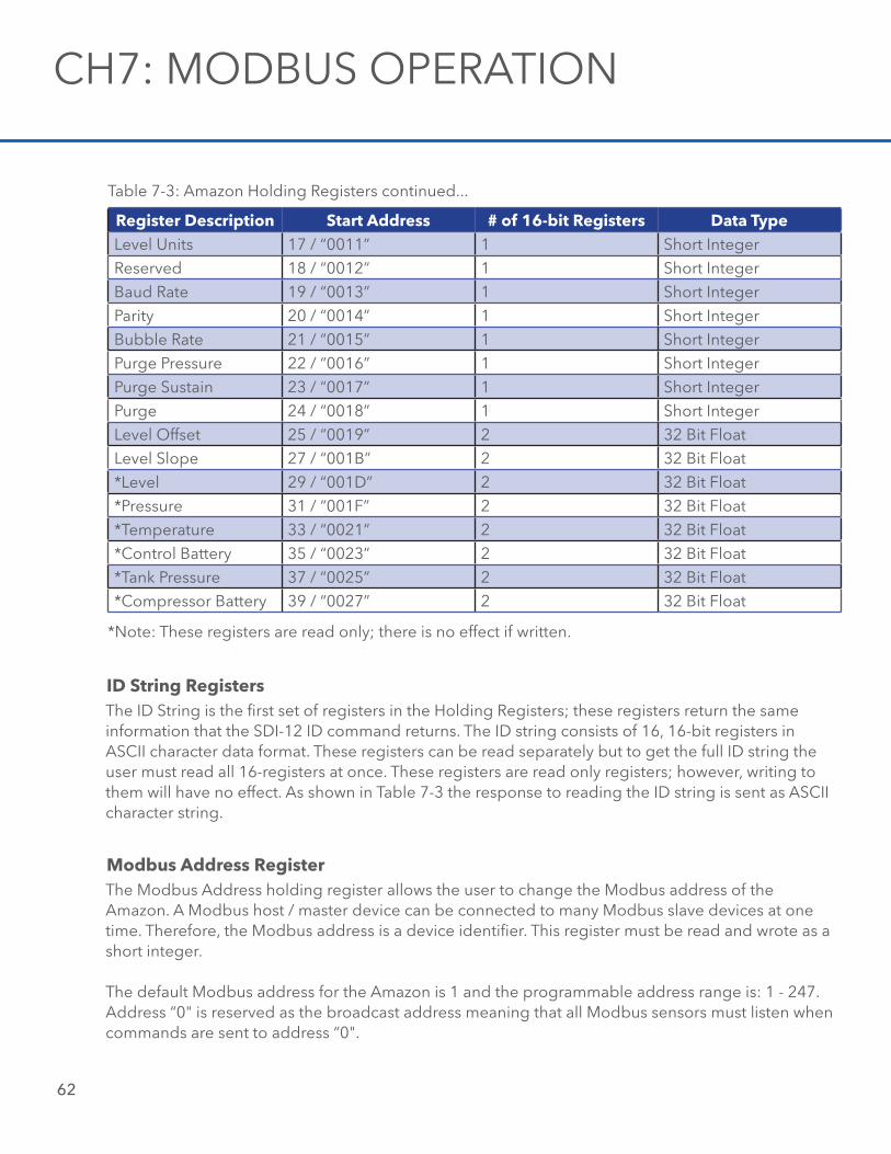
62
Register Description Start Address # of 16-bit Registers Data TypeLevel Units 17 / “0011” 1 Short IntegerReserved 18 / “0012” 1 Short IntegerBaud Rate 19 / “0013” 1 Short IntegerParity 20 / “0014” 1 Short IntegerBubble Rate 21 / “0015” 1 Short IntegerPurge Pressure 22 / “0016” 1 Short IntegerPurge Sustain 23 / “0017” 1 Short IntegerPurge 24 / “0018” 1 Short IntegerLevel Offset 25 / “0019” 2 32 Bit FloatLevel Slope 27 / “001B” 2 32 Bit Float*Level 29 / “001D” 2 32 Bit Float*Pressure 31 / “001F” 2 32 Bit Float*Temperature 33 / “0021” 2 32 Bit Float*Control Battery 35 / “0023” 2 32 Bit Float*Tank Pressure 37 / “0025” 2 32 Bit Float *Compressor Battery 39 / “0027” 2 32 Bit Float
Table 7-3: Amazon Holding Registers continued...
*Note: These registers are read only; there is no effect if written.
ID String RegistersThe ID String is the first set of registers in the Holding Registers; these registers return the same information that the SDI-12 ID command returns. The ID string consists of 16, 16-bit registers in ASCII character data format. These registers can be read separately but to get the full ID string the user must read all 16-registers at once. These registers are read only registers; however, writing to them will have no effect. As shown in Table 7-3 the response to reading the ID string is sent as ASCII character string.
Modbus Address RegisterThe Modbus Address holding register allows the user to change the Modbus address of the Amazon. A Modbus host / master device can be connected to many Modbus slave devices at one time. Therefore, the Modbus address is a device identifier. This register must be read and wrote as a short integer.
The default Modbus address for the Amazon is 1 and the programmable address range is: 1 - 247. Address “0" is reserved as the broadcast address meaning that all Modbus sensors must listen when commands are sent to address “0".
CH7: MODBUS OPERATION
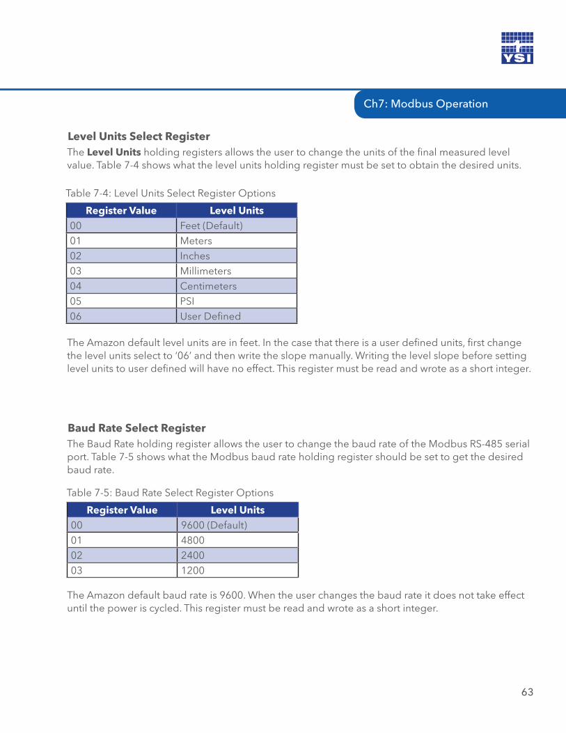
Ch7: Modbus Operation
63
Level Units Select RegisterThe Level Units holding registers allows the user to change the units of the final measured level value. Table 7-4 shows what the level units holding register must be set to obtain the desired units.
Register Value Level Units00 Feet (Default)01 Meters02 Inches03 Millimeters04 Centimeters05 PSI06 User Defined
Table 7-4: Level Units Select Register Options
The Amazon default level units are in feet. In the case that there is a user defined units, first change the level units select to ‘06’ and then write the slope manually. Writing the level slope before setting level units to user defined will have no effect. This register must be read and wrote as a short integer.
Baud Rate Select RegisterThe Baud Rate holding register allows the user to change the baud rate of the Modbus RS-485 serial port. Table 7-5 shows what the Modbus baud rate holding register should be set to get the desired baud rate.
Register Value Level Units00 9600 (Default)01 480002 240003 1200
Table 7-5: Baud Rate Select Register Options
The Amazon default baud rate is 9600. When the user changes the baud rate it does not take effect until the power is cycled. This register must be read and wrote as a short integer.
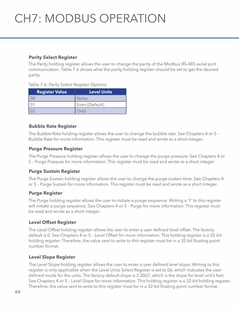
64
Parity Select Register The Parity holding register allows the user to change the parity of the Modbus RS-485 serial port communication. Table 7-6 shows what the parity holding register should be set to get the desired parity.
Register Value Level Units00 None01 Even (Default)02 Odd
Table 7-6: Parity Select Register Options
Bubble Rate Register
The Bubble Rate holding register allows the user to change the bubble rate. See Chapters 4 or 5 – Bubble Rate for more information. This register must be read and wrote as a short integer.
Purge Pressure Register
The Purge Pressure holding register allows the user to change the purge pressure. See Chapters 4 or 5 – Purge Pressure for more information. This register must be read and wrote as a short integer.
Purge Sustain Register
The Purge Sustain holding register allows the user to change the purge sustain time. See Chapters 4 or 5 – Purge Sustain for more information. This register must be read and wrote as a short integer.
Purge Register
The Purge holding register allows the user to initiate a purge sequence. Writing a ‘1’ to this register will initiate a purge sequence. See Chapters 4 or 5 – Purge for more information. This register must be read and wrote as a short integer.
Level Offset Register
The Level Offset holding register allows the user to enter a user defined level offset. The factory default is 0. See Chapters 4 or 5 – Level Offset for more information. This holding register is a 32-bit holding register. Therefore, the value sent to write to this register must be in a 32-bit floating point number format.
Level Slope Register
The Level Slope holding register allows the user to enter a user defined level slope. Writing to this register is only applicable when the Level Units Select Register is set to 06, which indicates the user defined mode for the units. The factory default slope is 2.3067, which is the slope for level unit’s feet. See Chapters 4 or 5 – Level Slope for more information. This holding register is a 32-bit holding register. Therefore, the value sent to write to this register must be in a 32-bit floating point number format.
CH7: MODBUS OPERATION
Ch7: Modbus Operation
65
Level Register
The Level holding register holds the current measured water level value. This holding register is a 32-bit holding register. Level is the result of the pressure in the line multiplied by the level slope and added to the level offset.
Pressure Register
The Pressure holding register holds the current measured pressure value before the slope and offset is applied. Therefore, it holds the raw PSI value. This holding register is a 32-bit holding register.
Temperature Register
The Temperature holding register holds the current measured temperature. The temperature reading is the temperature of the internal pressure sensor and may not accurately reflect air temperature.
Control Battery Register
The Control Battery holding register holds the current measured battery connected to the control circuit board or sensor interface cable power connections. This holding register is a 32-bit holding register.
Tank Pressure Register
The Tank Pressure holding register holds the current measured tank pressure value. This holding register is a 32-bit holding register.
Compressor Battery Register
The Compressor Battery holding register holds the current measured battery connected to the Amazon. This holding register is a 32-bit holding register.
Below are some examples of Modbus commands and their format.
Example #1: Read Holding Register Command:
Format: “aabbccccddddeeee”
Where: aa = 1 byte Modbus address bb = 1 byte function code cccc = 2 byte start address dddd = 2 byte quantity of registers eeee = 2 byte crc check
Example: 010300010001D5CA
Modbus Command Examples
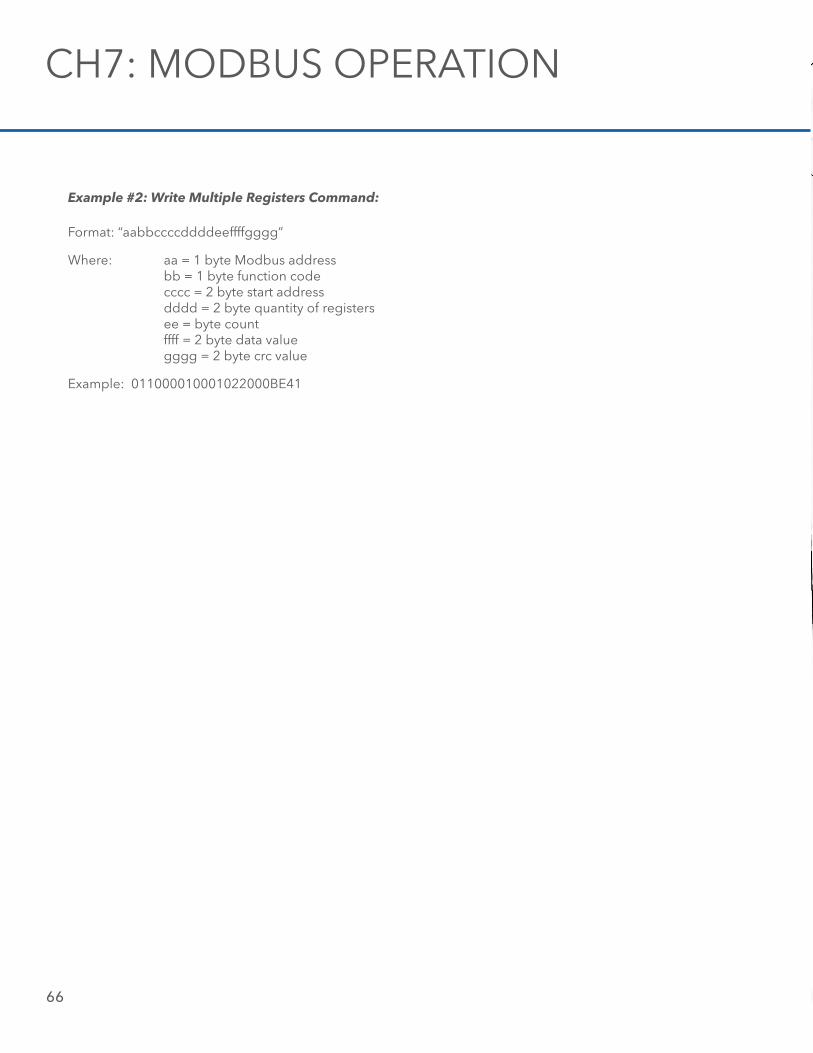
66
Example #2: Write Multiple Registers Command:
Format: “aabbccccddddeeffffgggg”
Where: aa = 1 byte Modbus address bb = 1 byte function code cccc = 2 byte start address dddd = 2 byte quantity of registers ee = byte count ffff = 2 byte data value gggg = 2 byte crc value
Example: 011000010001022000BE41
CH7: MODBUS OPERATION
08 / APPENDIX
67
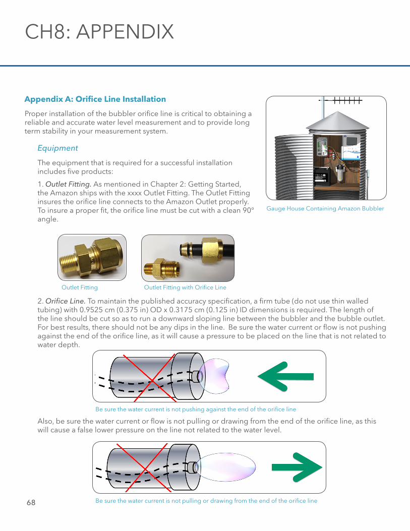
68
Appendix A: Orifice Line Installation
Proper installation of the bubbler orifice line is critical to obtaining a reliable and accurate water level measurement and to provide long term stability in your measurement system.
Equipment
The equipment that is required for a successful installation includes five products:
1. Outlet Fitting. As mentioned in Chapter 2: Getting Started, the Amazon ships with the xxxx Outlet Fitting. The Outlet Fitting insures the orifice line connects to the Amazon Outlet properly. To insure a proper fit, the orifice line must be cut with a clean 90° angle.
Gauge House Containing Amazon Bubbler
Outlet Fitting with Orifice Line
2. Orifice Line. To maintain the published accuracy specification, a firm tube (do not use thin walled tubing) with 0.9525 cm (0.375 in) OD x 0.3175 cm (0.125 in) ID dimensions is required. The length of the line should be cut so as to run a downward sloping line between the bubbler and the bubble outlet. For best results, there should not be any dips in the line. Be sure the water current or flow is not pushing against the end of the orifice line, as it will cause a pressure to be placed on the line that is not related to water depth.
Outlet Fitting
Be sure the water current is not pushing against the end of the orifice line
Also, be sure the water current or flow is not pulling or drawing from the end of the orifice line, as this will cause a false lower pressure on the line not related to the water level.
Be sure the water current is not pulling or drawing from the end of the orifice line
CH8: APPENDIX
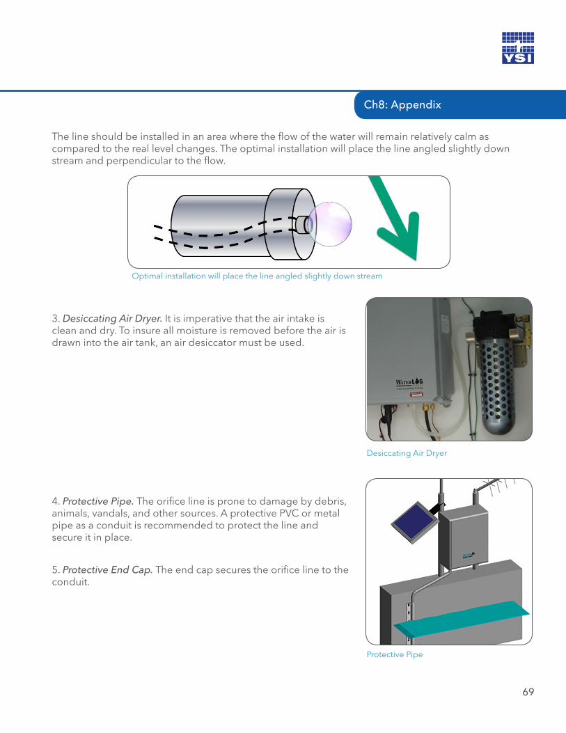
Gauge House Containing Amazon Bubbler
Ch8: Appendix
69
The line should be installed in an area where the flow of the water will remain relatively calm as compared to the real level changes. The optimal installation will place the line angled slightly down stream and perpendicular to the flow.
Optimal installation will place the line angled slightly down stream
3. Desiccating Air Dryer. It is imperative that the air intake is clean and dry. To insure all moisture is removed before the air is drawn into the air tank, an air desiccator must be used.
Desiccating Air Dryer
4. Protective Pipe. The orifice line is prone to damage by debris, animals, vandals, and other sources. A protective PVC or metal pipe as a conduit is recommended to protect the line and secure it in place.
Protective Pipe
5. Protective End Cap. The end cap secures the orifice line to the conduit.
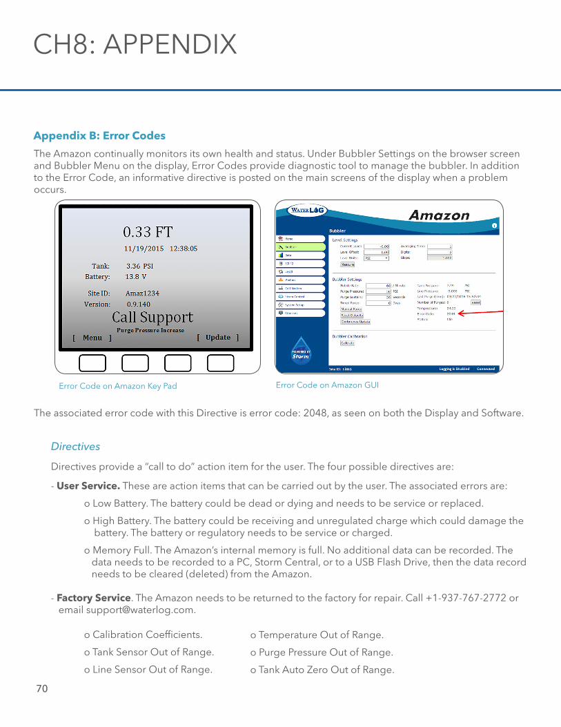
70
Appendix B: Error Codes
The Amazon continually monitors its own health and status. Under Bubbler Settings on the browser screen and Bubbler Menu on the display, Error Codes provide diagnostic tool to manage the bubbler. In addition to the Error Code, an informative directive is posted on the main screens of the display when a problem occurs.
Error Code on Amazon Key Pad Error Code on Amazon GUI
The associated error code with this Directive is error code: 2048, as seen on both the Display and Software.
Directives
Directives provide a “call to do” action item for the user. The four possible directives are:
- User Service. These are action items that can be carried out by the user. The associated errors are:
o Low Battery. The battery could be dead or dying and needs to be service or replaced.
o High Battery. The battery could be receiving and unregulated charge which could damage the battery. The battery or regulatory needs to be service or charged.
o Memory Full. The Amazon’s internal memory is full. No additional data can be recorded. The data needs to be recorded to a PC, Storm Central, or to a USB Flash Drive, then the data record needs to be cleared (deleted) from the Amazon.
- Factory Service. The Amazon needs to be returned to the factory for repair. Call +1-937-767-2772 or email [email protected].
o Calibration Coefficients.
o Tank Sensor Out of Range.
o Line Sensor Out of Range.
o Temperature Out of Range.
o Purge Pressure Out of Range.
o Tank Auto Zero Out of Range.
CH8: APPENDIX
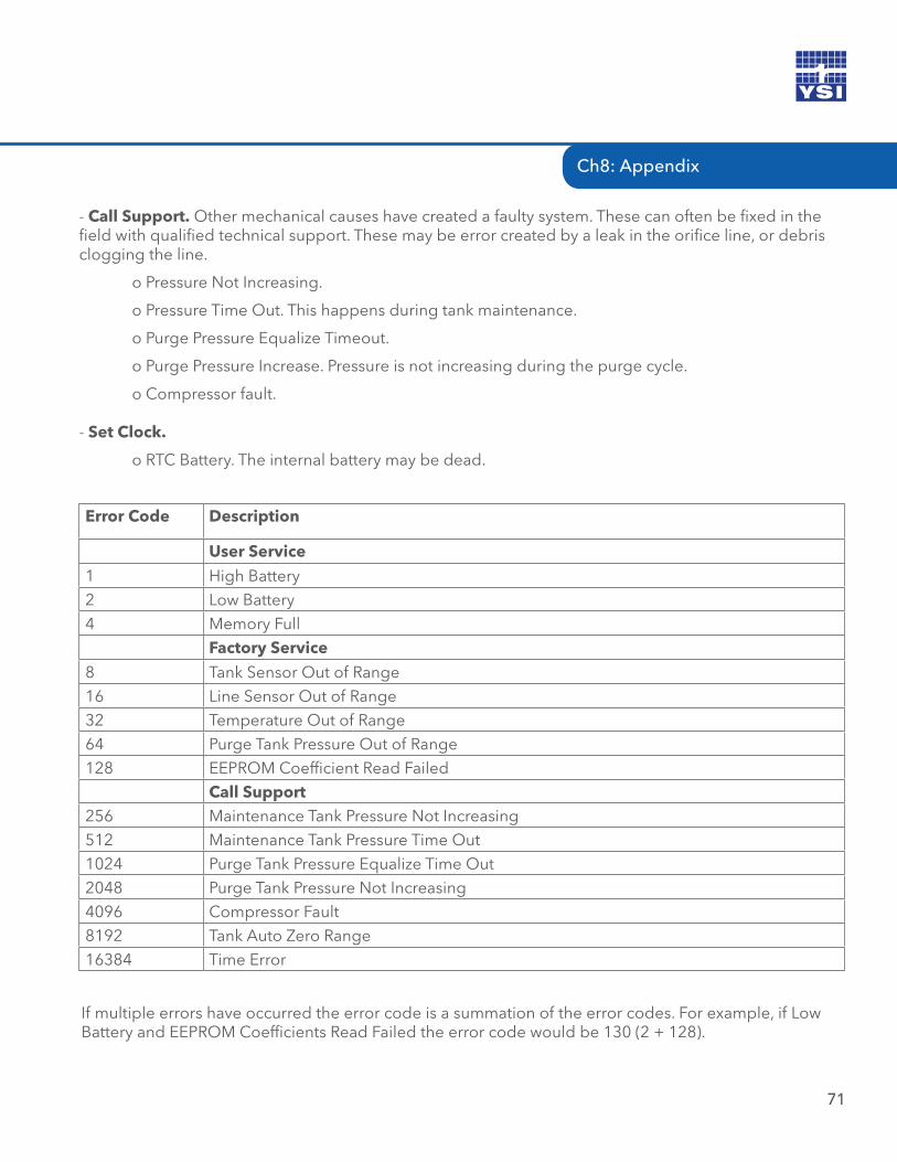
Ch8: Appendix
71
- Call Support. Other mechanical causes have created a faulty system. These can often be fixed in the field with qualified technical support. These may be error created by a leak in the orifice line, or debris clogging the line.
o Pressure Not Increasing.
o Pressure Time Out. This happens during tank maintenance.
o Purge Pressure Equalize Timeout.
o Purge Pressure Increase. Pressure is not increasing during the purge cycle.
o Compressor fault.
- Set Clock.
o RTC Battery. The internal battery may be dead.
Error Code Description
User Service
1 High Battery2 Low Battery4 Memory Full
Factory Service
8 Tank Sensor Out of Range16 Line Sensor Out of Range32 Temperature Out of Range64 Purge Tank Pressure Out of Range128 EEPROM Coefficient Read Failed
Call Support256 Maintenance Tank Pressure Not Increasing512 Maintenance Tank Pressure Time Out1024 Purge Tank Pressure Equalize Time Out2048 Purge Tank Pressure Not Increasing4096 Compressor Fault8192 Tank Auto Zero Range16384 Time Error
If multiple errors have occurred the error code is a summation of the error codes. For example, if Low Battery and EEPROM Coefficients Read Failed the error code would be 130 (2 + 128).
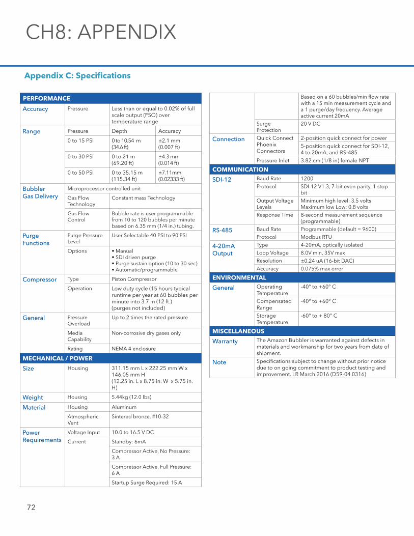
72
Appendix C: Specifications
Based on a 60 bubbles/min flow rate with a 15 min measurement cycle and a 1 purge/day frequency. Average active current 20mA
Surge Protection
20 V DC
Connection Quick Connect PhoenixConnectors
2-position quick connect for power5-position quick connect for SDI-12, 4 to 20mA, and RS-485
Pressure Inlet 3.82 cm (1/8 in) female NPT
COMMUNICATION
SDI-12 Baud Rate 1200Protocol SDI-12 V1.3, 7-bit even parity, 1 stop
bit
Output VoltageLevels
Minimum high level: 3.5 voltsMaximum low Low: 0.8 volts
Response Time 8-second measurement sequence(programmable)
RS-485 Baud Rate Programmable (default = 9600)
Protocol Modbus RTU
4-20mAOutput
Type 4-20mA, optically isolated
Loop Voltage 8.0V min, 35V max
Resolution ±0.24 uA (16-bit DAC)
Accuracy 0.075% max error
ENVIRONMENTAL
General Operating Temperature
-40° to +60° C
Compensated Range
-40° to +60° C
StorageTemperature
-60° to + 80° C
MISCELLANEOUS
Warranty The Amazon Bubbler is warranted against defects in materials and workmanship for two years from date of shipment.
Note Specifications subject to change without prior notice due to on going commitment to product testing and improvement. LR March 2016 (D59-04 0316)
PERFORMANCE
Accuracy Pressure Less than or equal to 0.02% of full scale output (FSO) over temperature range
Range Pressure Depth Accuracy
0 to 15 PSI 0 to 10.54 m(34.6 ft)
±2.1 mm(0.007 ft)
0 to 30 PSI 0 to 21 m(69.20 ft)
±4.3 mm(0.014 ft)
0 to 50 PSI 0 to 35.15 m(115.34 ft)
±7.11mm(0.02333 ft)
BubblerGas Delivery
Microprocessor controlled unit
Gas Flow Technology
Constant mass Technology
Gas Flow Control
Bubble rate is user programmable from 10 to 120 bubbles per minute based on 6.35 mm (1/4 in.) tubing.
Purge Functions
Purge Pressure Level
User Selectable 40 PSI to 90 PSI
Options • Manual• SDI driven purge• Purge sustain option (10 to 30 sec)• Automatic/programmable
Compressor Type Piston Compressor
Operation Low duty cycle (15 hours typical runtime per year at 60 bubbles per minute into 3.7 m (12 ft.)(purges not included)
General PressureOverload
Up to 2 times the rated pressure
MediaCapability
Non-corrosive dry gases only
Rating NEMA 4 enclosure
MECHANICAL / POWER
Size Housing 311.15 mm L x 222.25 mm W x 146.05 mm H (12.25 in. L x 8.75 in. W x 5.75 in. H)
Weight Housing 5.44kg (12.0 lbs)
Material Housing Aluminum
AtmosphericVent
Sintered bronze, #10-32
Power Requirements
Voltage Input 10.0 to 16.5 V DC
Current Standby: 6mA
Compressor Active, No Pressure: 3 A
Compressor Active, Full Pressure: 6 A
Startup Surge Required: 15 A
CH8: APPENDIX
Ch8: Appendix
73
This user manual is a guide for the Amazon Bubbler. For more information, updated manuals, brochures, technical notes, and supporting software on the Amazon Bubbler, please refer to ysi.com/Amazon or contact your sales representative.
For additional assistance, please contact us at +1.435.753.2212 or [email protected]
1) The tissue in plants that brings water upward from the roots;2) A leading global water technology company.
We’re 12,000 people unified in a common purpose: creating innovative solutionsto meet our world’s water needs. Developing new technologies that will improvethe way water is used, conserved, and re-used in the future is central to our work.We move, treat, analyze, and return water to the environment, and we help peopleuse water efficiently, in their homes, buildings, factories and farms. In more than150 countries, we have strong, long-standing relationships with customers whoknow us for our powerful combination of leading product brands and applicationsexpertise, backed by a legacy of innovation.
For more information on how Xylem can help you, go to www.xyleminc.com
Xylem
YSI Incorporated
1700/1725 Brannum Lane
Yellow Springs, Ohio, 45387, USA
Request a Quote
Tel: +1.435.753.2212
Email: [email protected]
Internet: www.ysi.com/amazon
Place an Order
Tel: +1.937.767.7241
Email: [email protected]
Customer Support
Tel: +1.937.767.2772
Email: [email protected]
©2016 Xylem Inc. Item#361756REF dwg#361756August 2016 Rev DD84-06 0816