alupanel fabrication guidelines - denco sales · 04 safety, storage and handling safety, storage...
TRANSCRIPT
AlupanelFabricationGuidelines

02 Contents
Contents
a multitude of applications
Product Description
Safety, Storage & Handling
Visual Consistency & Sawing
Saw Equipment
Routing & Folding
Recommendations by Manufacturer
Additional Manufacturer Information
Corner Cutting & Bending
Joining Techniques
Coating / Printing / Cleaning Alupanel
Thermal Expansion
Compensation of Thermal Expansion
Wind Load Calculation
3
4
5
6
7
8
9
15
16
19
21
22
24
UK Head Offi ceUnit 6, Site 2, Oak Business Units,Thorverton Road, Matford, Exeter,Devon, EX2, 8FS Tel: +44 (0) 1392 823015
Northern Europe Offi ce Tel: +31 (0) 55 323 09 50
USA Offi ceTel: +1 718 841 9940
www.multipaneluk.co.uk

Product Description 03
Product Description
UK Head Offi ce Tel: +44 (0) 1392 823015 • N. Europe Offi ce Tel: +31 (0) 55 323 09 50 • USA Offi ce Tel: +1 718 841 9940
www.multipaneluk.co.uk
Alupanel is a high-performance composite material consisting of two aluminium sheets bonded to an extruded thermoplastic core. As a result of this technology, we have created a perfectly fl at and very formable material with an excellent strength-to-weight ratio.
Alupanel is supplied with a face PE paint fi nish, available in the widest colour range on the market.
The fl exibility of the panel makes it a perfect material for sign makers, designers, architects, fabricators and installers.
Advantages include:
• Exceptional rigidity• Outstanding strength to weight ratio• Simple to fabricate • Easy and quick to install• High resistance to atmospheric conditions• Easy to maintain
This manual has been developed to assist fabricators and installers to work with Alupanel in the most effi cient manner possible. The following recommendations and product data are based on information
which is, in our opinion, reliable. However, since skill, judgment, and quality of equipment and tools are involved, and since conditions and methods of using Alupanel are beyond our control, the suggestions contained in this manual are provided without guarantee. We recommend that prospective users determine the suitability of both the material and recommendations before adopting them on a commercial
scale. In no event shall Multipanel UK Ltd, have any liability in any way related to or arising out of said suggestions and product data for direct, special, consequential or any other damages of any kind.

04 Safety, Storage and Handling
Safety, Storage and Handling
a multitude of applications
Safety:Standard health and safety precautions should be adhered to when fabricating Alupanel Material. Goggles or other face protection, as well as hearing protection and gloves should always be worn. An MSDS for Alupanel is available from your local sales representative or distributor.
Packaging:Alupanel comes as standard with a clear protective fi lm, designed to be removed just before installation to offer protection from surface damage. Although the protective fi lm is UV stabilised, it should be removed as soon as possible after installation, especially in the case of panels exposed to sunlight and adverse weather.
Handling:Alupanel should be handled with care, especially when dealing with long lengths. It is advisable that a small team carry out the handling. When removing panels from a pallet / stack never drag the panel, always lift clear above the remaining panels on the stack. This will require two or more operatives.
Storage:When storing unpacked Alupanel please observe the following guidelines:
• To prevent warping or bending, store horizontally.• Avoid stacking Alupanel of different sizes together, as the surface or panel can be damaged by the edges of the smaller pieces.• Preferably, store them by size in racks.• If storing panels vertically by leaning them against a rack, lay a rubber mat underneath and lean the Alupanel closely against the fi xed back.• Alupanel is packed in wooden crates and can usually be stacked up to four crates high.• It is advisable to store Alupanel in a clean dry area with a minimum temperature of 15°C for a duration of 24 hours before use. After 24 hours of storage you will be able to start the processing requirements for each panel. After Alupanel has been removed from the stack it must be protected from any penetrating moisture.

Visual Consistency / Sawing 05
Visual Consistency & Sawing
UK Head Offi ce Tel: +44 (0) 1392 823015 • N. Europe Offi ce Tel: +31 (0) 55 323 09 50 • USA Offi ce Tel: +1 718 841 9940
www.multipaneluk.co.uk
Visual consistency:Each of our product types has special characteristics that can affect the visual consistency from batch to batch and even from panel to panel. It is important that these characteristics be considered when planning how to use and install Alupanel.
Solid colours: The industry standard for allowable variation for panel to panel and batch to batch is Delta E 1.0 or less in a hunter colour space. Brighter colours, such as reds, yellows, blues, etc, which tend to be less opaque and which depend somewhat on fi lm build (paint thickness) to achieve their appearance, will be more likely to exhibit more variation than subdued colours.
Projects - same batch
Metallic colours: The industry standard for colour variation with metallic is Delta E 2.5 or less, much larger than the standard for solid colours.
Directional project: In coating the fl akes will tend to align in one direction. This greatly increases the directionality of the panel’s appearance.
Production Batches/Projects:When working on projects it is
highly recommended that material from the same production batch is used in order to maintain overall visual consistency.
For these reasons the panels must be installed with the directional arrows all aligned in the same direction. Batches should not be mixed on a building face without fi rst contacting Multipanel UK Ltd for a confi rmation that they are visually similar enough to be used together.
Before fabrication, remember to use a felt tip pen to draw arrows to indicate the coating direction on any small pieces that might be cut out from areas without the directional arrows.
Sawing:Sawing Alupanel is an easy process that can be done with ordinary commercial metal and woodworking equipment. Saw blades and router bits are available through independent distributors who handle cutting tools. Prior to processing large quantities, trial saw cuttings should be done to evaluate both the tool working conditions and the recommended cutting speeds. For marking the panels the use of a soft pencil is adequate. Hard marking tools should be avoided as they can fracture the Aluminium surface. It is recommended that
the swarf formed during cutting should be vacuumed away with compressed air. Due to the nature of the Alupanel it is best to move the saw blade rather than the material as no scratch will remain on the panel. If good saw cutting practices are applied and recommendations followed, the result should be clean cuts with little bur. If despite following the recommendations, ragged cuts are produced check the following causes; poor tool support tool vibration blunt cutting edges high frictional heat at the cutting edge
As Alupanel has low thermal conductivity it cannot be cooled easily with compressed air or any other means. Therefore it is recommended to select the tool geometry and cutting conditions in such a manner so as to minimize the frictional forces developed at the cutting point and keep the resulting heat at a low level.

06 Saw equipment
Saw EquipmentSaw cutting can be accomplished with the following equipment:
a multitude of applications
Panel Saws: Panel saws provide an effective method of cutting. These saws, whether standard equipment or custom made, perform well and have the added advantage of space saving. If a panel saw is to be used as production equipment, an industrial model should be purchased in order to obtain adequate cutting tolerances and increase the longevity of the equipment.
Table Saws:Table saws are not recommended for large sheets.
Multiple Operation Rip/V-Grooving Saws: In high production operations, equipment that is capable of performing more than one operation with a single pass through the machinery is recommended. This equipment can make multiple saw cuts (sizing the panel) and V-Grooves (rout) at the same time.
Portable Circular Saws:Cutting Alupanel with portable circular saws is another effective method. As mentioned, this equipment should also be production/industrial standard equipment.
Jig Saws: Jig saws work well for cut-outs. Care should be taken with portable jig saws to prevent damage to the Alupanel material surface. More than one sheet can be cut at a time by stacking panels.
If centre cutting (i.e., letter cut-outs) is required, a foam pad may be placed under the material with the blade cutting into the foam. The sheets may be clamped or secured with double-sided tape for the cutting operation. When clamping between jaws, protect the panel surface against damage.
Working Method
Cutting Material
Blade/Band Geometry
Tooth Geometry
Max. Cutting Speed
Max. Cutting Feed
Circular Saws Carbide tipped orhighspeed steel
20 x 35mm blades with maximum number of carbide teeth available, designed for cutting non-ferrous material. The blade should be ground thinner from the rim towards the centre to prevent pinching.
Angle or circular tooth, alternate bevelled, tripleground. Tooth gap wall rounded. Chip angle: 5°to15°.Clearance angle:10°to 30°. Tooth spacing: 4mm to 25 mm, fi ne spacing preferable.
5500 RPM 0.10 - 40 mm/sec
Band Saws Tempered springstrip steel.
Thickness: 0.8 mm to 1.2 mm. Width: 15 mm to 25 mm. Use racket or straight set.
Skip teeth, designed for nonferrous and ferrous materials (light metals and plastics). Tooth spacing: minimum 4 teeth per cm.
10000 RPM 25mm/sec
Reciprocatingsaws
High speed steel. Thickness: 0.8 mm to 1.2 mm. Width: 5 mm to15 mm).
Hook or circular tooth with alternate angles, set or waved. Tooth spacing: 2 mm to 6 mm
10 mm/sec
96 and 72 teeth carbon blades with negative teeth (Dents affutage negative). Both work well but 96 is reccomened. Suggested Blade Manufacturers: LEITZ /FREUD / AKE / HELLER / LEUCO / ISOCELE

Routing & Folding 07
Routing & Folding Introduction
UK Head Offi ce Tel: +44 (0) 1392 823015 • N. Europe Offi ce Tel: +31 (0) 55 323 09 50 • USA Offi ce Tel: +1 718 841 9940
www.multipaneluk.co.uk
Alupanel can be routed using conventional Routing machines. For accurate and precise manual folding of the Alupanel composite panels, resulting in a good fi nish, we recommend to route the rear of the panels to a depth of 2.5mm thick, going through the exterior aluminium layer, and some of the Polyethylene core. Normally the panel is grooved and folded 25-70mm from the edge.
In order to route Alupanel the following equipment is necessary:
Vertical panel saw: Equipped with specially shaped routing saw blades. The equipment needed is the same vertical saw as the one used for the cutting, but with a different saw blade and relevant equipment for adjusting the routing thickness.
The use of a chip collector is essential.
Portable circular saw: A portable circular saw equipped with a suitable routing disk can be used, but only for a limited amount of processes. Note that special care should be given to the stability of the portable circular
saw during processing of the material, as well as the precision of the routings with the help of the chosen guided system.
Hand operated router:These tools consist of routers that are commonly available on the market and are used for wood processing. If they are equipped with special routing bits (carbide tipped cutter) the hand operated router can be used for a limited number of processes. In this case the stability of the tool and the guide-system considerably affect the quality of the routing.
Work directions:For shaped elements with a radius of between 2-7mm proceed as follows:
• The shape of the groove and its respective depth determines the folding radius. Note that smooth bending (shape forming of elements) cannot be obtained without uniform thickness of polyethylene remaining.

08 Recommendations by Manufacturer
Recommendationsby Manufacturer
a multitude of applications
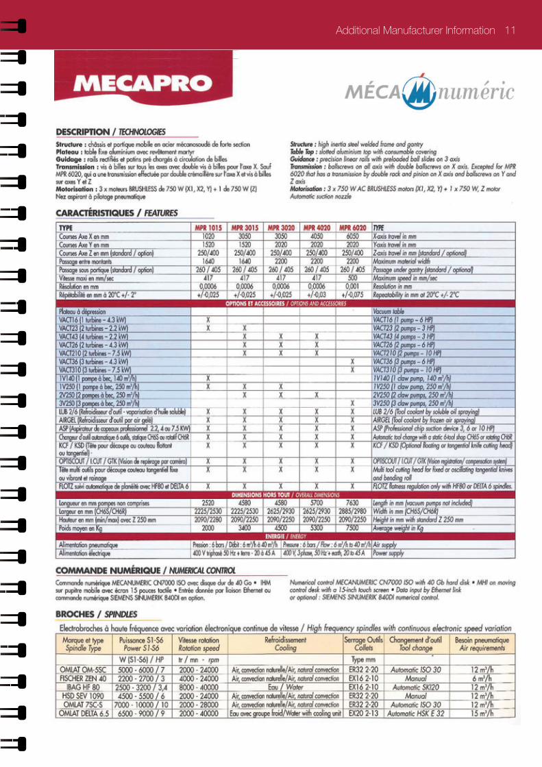
Maximum RPM of Spindle
Esko 40000rpm
Esko 55000rpm
Zund 46600rpm
Meca 50000rpm
Tekcel 24000rpm
Type of tool (4mm cutter)
BIT - MUS06-4006-50C1
BIT - MUS06-4006-50C1
R104 4mm 4mm CP-AL 4-8-6
Recommended Feed Rate
83 mm/s 200 mm/s 200 mm/s 250 mm/s 85 mm/s
Recommended Routing Depth: Material thickness remaining after routing is usually between 1,5 -2 times skin thickness
Alupanel 0.45 - 0.6
Alupanel Light 0.35 (not recommended)
Ecopanel 0.25 (not recommended)
Note: All data obtained after in-house testing by manufacturer’s stated above.
Material Tested: Alupanel 3mm (0.3)
For Alupanel 2mm, Alupanel 2mm Lite and 3mm Lite we would recommend comparable speeds as stated above.
We always recommend that you allow time for your own indivdual test procedures, depending on Machine Version and always seek advice from an experienced user.
If further detail is requiered please contact your re-seller.
Routing & Folding 09
Additional Manufacturer Information
The additional information contained has been supplied by your chosen manufacturer:

10 Additional Manufacturer Information
Bit used for ACM
BIT- MUS06-2006-50C1 2 mm diameter BIT- MUS06-3006-50C1 3 mm diameter BIT- MUS06-4006-50C1 4 mm diameter
XP XN 5 m/min 5 m/min 50 % ACC 80 ACC z : 1m/min z : 1m/min TR/MN : 40 000 TR/MN : 40 000
XP XN
12 m/min 12 m/min50 % ACC 80 ACC z : 1m/min z : 1m/minTR/MN : 55 000 TR/MN : 55 000
ACM Mutlipanel Setting Kongsberg
1 kw Spindel 3 kw Spindel
Additional Manufacturer Information 11

12 Additional Manufacturer Information
For more information or CNC cutter sales:
Email : [email protected]él. : +44 (0) 1275 342 668Fax. : +44 (0) 1275 342 669
General Guidelines
Cutter Choice
Cutting Multipanel Sheet Materials
Pliage de matériaux en feuille Multipanel
Copyright Tekcel CNC Solutions 2012
Machine Fold Lines
Cut Out in One Pass
Tekcel CP-AL Cutters
Tekcel GP Cutters
Tekcel FC Cutters
Accurate Depth Control
Perfect Results
FOLDING / CUTTING MULTIPANEL SHEET PRODUCTS
Product Code Cutting Dia. Max. Cut Length Shank Dia.
CP-A1 3-6-6 3 mm 6 mm 6 mm
CP-A1 3-6-6 4 mm 8 mm 6 mm
CP-A1 3-6-6 6 mm 14 mm 6 mm
Product Code Angle Shank Dia.
FC-90 3 mm 8 mm
FC-135 4 mm 8 mm
Product Code Cutting Dia. Max. Cut Length Shank Dia.
GP 2-10-6 2 mm 10 mm 6 mm
GP 3-12-6 3 mm 12 mm 6 mm
GP 4-15- 6 4 mm 15 mm 6 mm
GP 6-20-6 6 mm 20 mm 6 mm

Additional Manufacturer Information 13
ACM Multipanel Setting Zund
Applicable bits:
R104 4 mm diameterR105 5 mm diameter R106 6 mm diameter
Routing speeds:
XY speed = 200 mm/sAcceleration = 4 (100 %)Router speed = 46600 Tr/mn

14 Routing & Folding
a multitude of applications
Routing & Folding Methods
Grooving equipment:For processing a small numberof panels a manual router with a v-groove blade and trimmercan be used.
For processing largevolumes a table circular saw/CNC router and a grooving cutter are needed along with a lifter. Technical characteristics of carbide saw-tip:
Outside diameter: 305 No of the teeth: 24 RPM: 3000 to 5000
Carbide Saw:By routing on just one of the sides of Alupanel, it can be bent upwards or downwards to create both an inside or outside corner.
When a groove is bent at a 90° angle the bending radius of the fi nal product will be 3-3.5mm and the element will elongate by 0.5-1.0mm. As such, the original panels should be cut shorter by that proportion.

UK Head Offi ce Tel: +44 (0) 1392 823015 • N. Europe Offi ce Tel: +31 (0) 55 323 09 50 • USA Offi ce Tel: +1 718 841 9940
Corner Cutting & Bending 15
Corner Cutting &Bending
Wood chisel: A sharp hammer blow to a wood chisel allows you to cut out the small thickness at the bottom of a routing groove with no diffi culty. The wood chisel must be wider than the part to be cut out. With a little experience, good clean joints can be easily achieved.
Punching:This technique is the most productive, with the corners being cut out and the corner fastening holes being achieved in a single operation.
The minimum bending radius for Alupanel without routing the back skin is fi fteen times the thickness of the panel being curved i.e., 4 mm = 60 mm minimum radius.
Alupanel can be cold formed in a pyramid roller, a press brake or over a clamped pipe. The process is similar to the forming of aluminium; however, due to the sensitive surface, care should be taken to ensure rollers are clean, smooth and free of defects to avoid damage to the surface.
Pyramid Roller:As an extra precaution, a protective fi lm should be used between the panel and the rollers to further shield the panel surface. Do not pinch the Alupanel between the rollers. Roll the panel 3° to 5° tighter to allow for a small amount of Spring back that will
occur. Once the sheet is curved; however, it will remain curved.
Press Brake:When forming with a press brake, use a top die (tubular) with the radius desired and open the bottom die (jaws) approximately two times the thickness of the material plus fi lm wider than the top die. The lower die should always have a protective pad of not less than 3mm fi lm.
Some adjustment of the lower jaws may be necessary to allow for varying bending properties between anodized and painted fi nish and for varying thicknesses. The radius of the top die will be the approximate inside radius of the fi nished panel.
Bending Over a Clamped Pipe:Alupanel may be formed over a
pipe of the proper diameter that is securely clamped to a work table. A hinged “leaf” attached to the end of the table will bend the material easily.
Pyramid Roller
Press Brake
Two methods are normally used for cutting out corners to allow the forming of a cassette.

16 Drilling / Joining
a multitude of applications
Joining Techniques One
Drilling:Alupanel can be drilled with standard drills used for aluminium and plastics.
Working Specifi cations:
Drill bit: Twist drill, high speed steel.
Tip Angle: 100-140 degrees, or counter-bore grind with centering tip.
Cutting speed: 164 RPM to 984 RPM.
Quick removal of chips can be achieved by a high RPM, slow feed speed and occasional lifting of the bit.
Joining:A variety of different fasteners are used to fabricate and install Alupanel. Structural adequacy and selection of these fasteners are the responsibility of qualifi ed engineers and in most instances where architectural panels are used, certifi ed calculations will be required by the Building Offi cial. You may successfully use specifi c fasteners for panel load testing purposes in obtaining building code recognition.
Please fi nd below some important general information about joining techniques. Use the following guidelines when other elements come in direct contact with the surface of Alupanel Material:
Acceptable joining materials: aluminium, plastic, stainless steel, plated or coated steel with cadmium, zinc or aluminum.
Unacceptable joining materials: copper, brass, bronze, iron, raw steel. Unacceptable materials cause corrosion of joining surfaces due to electrolysis of dissimilar materials. Therefore, use “heavy” or “red” metals only with an electrically insulating intermediate layer.
When joining elements are to be anodized, assemble the materials after the anodizing process. Proper consideration should be given to the thermal expansion characteristics of Alupanel Material when using any of the joining techniques.
Pop rivets are often used to attach aluminium clip angles and other structural or ornamental elements to Alupanel. Because the rivet body will be in contact with the aluminium skin of the panel, it
is recommended that either aluminium or stainless steel rivets be used to avoid dissimilar metals contacting. Ultimate shear and tensile strengths of various rivets are available from the rivet manufacturer.
Please be advised that some building code jurisdictions do not endorse the use of pop rivets for structural connections.
UK Head Offi ce Tel: +44 (0) 1392 823015 • N. Europe Offi ce Tel: +31 (0) 55 323 09 50 • USA Offi ce Tel: +1 718 841 9940
www.multipaneluk.co.uk
Screwing / Bolting 17
Joining Techniques Two
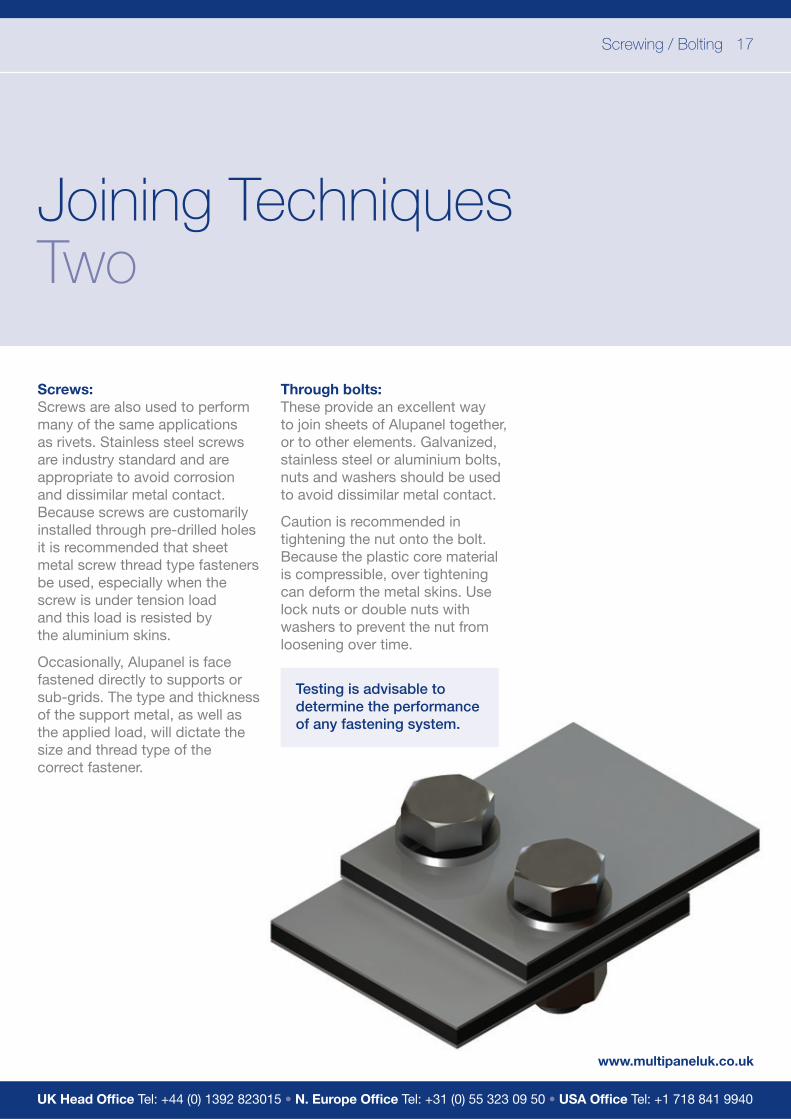
Screws:Screws are also used to perform many of the same applications as rivets. Stainless steel screws are industry standard and are appropriate to avoid corrosion and dissimilar metal contact. Because screws are customarily installed through pre-drilled holes it is recommended that sheet metal screw thread type fasteners be used, especially when the screw is under tension load and this load is resisted by the aluminium skins.
Occasionally, Alupanel is face fastened directly to supports or sub-grids. The type and thickness of the support metal, as well as the applied load, will dictate the size and thread type of the correct fastener.
Through bolts:These provide an excellent way to join sheets of Alupanel together, or to other elements. Galvanized, stainless steel or aluminium bolts, nuts and washers should be used to avoid dissimilar metal contact.
Caution is recommended in tightening the nut onto the bolt. Because the plastic core material is compressible, over tightening can deform the metal skins. Use lock nuts or double nuts with washers to prevent the nut from loosening over time.
Testing is advisable to determine the performance of any fastening system.

18 Welding / Adhesive Bonding
a multitude of applications
Joining Techniques Three
Welding:This method is frequently used to assemble Alupanel. The fi ller rod and the polyethylene core are welded together after heating by a jet of hot air projected by an electrically heated welding gun.
For good quality welding, you will need:• Good preparation of the edges to be welded together• Adequate fi ller rod quality• A good welding speed• Evenly applied pressure• Clean hot air• An appropriate temperature
Welding by the to-and-fro method:Hold the fi ller rod at a right angle whilst exerting regular pressure on the rod, make to-and-fro B-B (non-circular) movements. The fi ller rod and the edges to be welded must be heated in a similar way.
Welding using a high-speed nozzle:Normal hot air guns fi tted with a removable high-speed welding nozzle allow the edges to be welded and the fi ller rod to be heated at the same time. This makes for better quality welding. The fi ller rod is pushed by the constant pressure of the high-speed nozzle, and is therefore pressed between the edges to be welded.
Preparation of the edges to be welded:
Butt welding: The edges must be bevelled,
Corner assembly: Only one of the panels is bevelled.
T-assembly: Remove the narrow strip of metal skin to free the areas to be welded.
Welding of a fold: Bevel the edges to be welded fi rst of all using a shaped milling cutter.
The polyethylene core oxidizes relatively quickly once exposed to the air. It must be welded within 24 hours max after it is bevelled. Once it has cooled, it is possible to remove the welding fl ash using a knife or scraper. We recommend that this operation be carried out in a clean, oil and water-free area.
The specifi c welding qualities of the fi ller rod are:
Polyethylene: low density Colour: unpigmentedDensity: 0.9 g/cm3Diameter of rod: 3, 4 and 5mm
Immediately before welding,remove the outer layer of oxide from the fi ller rod.
Adhesive Bonding:In addition to structural adhesives, double sided tape can be used for fi xing Alupanel on fl at surfaces such as walls, ceilings, furniture, coverings etc.
Extreme care should be given when selecting the adhesive so as to ensure it is chosen according to the application and the environmental conditions.
* Non shrink on Drying is essential.
It is important that the manufacturer is consulted prior to the usage of the adhesive for further instructions.
The substrate surface should be clean before the application of the structural adhesive.

UK Head Offi ce Tel: +44 (0) 1392 823015 • N. Europe Offi ce Tel: +31 (0) 55 323 09 50 • USA Offi ce Tel: +1 718 841 9940
Printing / Cleaning 19
Coating / Printing / Cleaning Alupanel - ‘Easy Peel’ One
Easy Peel Protective Film ensures no residue is left on the panel, reducing cleaning time and eliminating the risk of interference with the print. An ultra white surface helps to display printed colours with increased brightness and intensity, with a special coating also delivering vastly improved ink adhesion for colour fast prints. Developed for the print market, Alupanel Ultrawhite is suitable for use both indoors and out and, is available with the reverse side milled and covered with transparent digital laquer providing perfect adhesion for prints, acheiving an amazing look of aluminium surface with colourfull prints.
Off-line Coating:Alupanel can be coated off-line if necessary. It is advisable to follow instructions as specifi ed by the manufacturer of any paints to be used.
For off-line coating observe the following guidelines:
• Surface should be lightly abraded to provide a better coating surface. The Surface should then be cleaned of all contaminates i.e. dust, dirt and oil etc. A soft cloth with a non- petroleum based solvent (e.g. rubbing alcohol) should be used to clean the surface area.
• Curing should be done at room temperature since temperatures above 1750F can cause Alupanel to deform.
Screen Printing:Alupanel is perfect for printing with an epoxy base or urethane base two-part type ink/paint. When selecting an ink, confi rm its weather ability and adhesion with the ink manufacturer. It is recommended to test the ink adhesion on the surface of Alupanel before printing.
For printing on Alupanel, observe the following guidelines:
• Remove all dust and dirt on the surface of Alupanel. Oily dirt causes splintering, splitting, or other defects of the paint. It must be completely removed with a soft cloth dipped in alcohol, N-hexane, etc. If storage or drying is not done correctly, the adhesion or other performance may be adversely affected. Therefore, observe the storing conditions of each paint as specifi ed by the manufacturer.
• Since storing in high temperature may cause deformation, ensure the storing temperature is kept below 1750F and store horizontally.

20 Welding / Adhesive Bonding
a multitude of applications
Coating / Printing / Cleaning Alupanel - ‘Easy Peel’Two
Cleaning:Alupanel should be regularly cleaned following the method below. The surface of the panel will commonly accumulate dust, dirt and other airborne particles. In the case of panels used externally, various hydrocarbons from airborne exhausts are also likely to need removal. It is also possible that surfaces could be contaminated with synthetic hydrocarbons from other exhausts such as synthetic grease, oil, hydraulic fl uids, lubricants or stains from vegetation like plant or animal matter.
Cleaning Method:We recommend a 4-step cleaning method:
1 Flush Alupanel with water from a hose.2 Wipe lightly with a soft cloth.3 Use pressure washer.4 Use detergent in a power wash or with a soft cloth for hand wiping and fl ush with water.
Alupanel & Alupanel UWD- pH test/print life-spanTests have been undertaken to determine the acidity of our Alupanel and Alupanel Ultra White Digital panels. An Insta-check pH pencil (by Micro Essential Laboratory) was used to carry out the tests.
The panel surface was moistened with distilled water and left for 3 minutes. Several lines were drawn with the Insta-Check pH pencil on the wet surface. After 15 seconds the color of the lines was compared with a pH color chart. The colours of the lines matched the colour on the chart corresponding to a pH level of 7, which indicates that the substance is neutral. In conclusion, we can state that the surface of our digital panels is not acidic and that coatings/paints applied will last for years. This means that Alupanel is suitable, for example, for archival applications.
Material Compatibility:Alupanel is an extremely durable material that has been designed to withstand signifi cant exposure to environmental conditions. It is unlikely to be compromised by any cleaning process that would conceivably be used on the material.
Easy Peel Protective Film No residue Reduce cleaning time Elimination of print interference Ultra white surface Bright and intense colours Vastly improved ink adhesion Suitable for indoors and out Available reverse side milled Digital laquer covering option
However, in the interests of maintaining the fi nish of the material, the prudent user will select products with a pH of 10 or less and which do not contain bleaches, ammonia or caustic ingredients such as sodium hydroxide, potassium hydroxide or sodium metasillicate. It is also recommended that users avoid abrasive materials or tools such as scouring powders, fi ber padsor brushes.

UK Head Offi ce Tel: +44 (0) 1392 823015 • N. Europe Offi ce Tel: +31 (0) 55 323 09 50 • USA Offi ce Tel: +1 718 841 9940
Thermal Expansion 21
Thermal Expansion
All the materials used in construction and sign making will expand when exposed to high temperatures and shrink when the temperature falls. Each material has its own thermal expansion rate. In the metric system it is measured in mm/m/100DC and shows how many milimiters one meter of material will expand when the temperature changes 100 degrees Celcius.
For example, for steel and concrete this rate is around 1,2mm and for PVC it is 5,2mm. When different materials are fi xed together it is always neccessary to take into account their expansion rates and exposure of those materials to different temperatures.
Sometimes it may happen that a substrate on which Alupanel is designed to be installed is rigidly fi xed without taking thermal expansion into consideration. In this case this substrate can bow and deform causing subsequent bowing of the Alupanel fi xed to this substrate. To prevent this substrates on which Alupanel is going to be installed shall be carefully examined.
Alupanel consists of 2 aluminium layers bonded to a polyethylene core. Thermal expansion of Alupanel is determined by the properties of its aluminium skins. Thermal defl ection of aluminium is 2,4 mm/m/100DC. So a 2440mm long panel with a100DC temperature fl uctuation will expand 5,86mm and its length will become 2445,86m under new temperature conditions.
At the same time if 2 edges of the panel are fi xed the tension in Aluminium skins will lead to panel bowing. Bowing defl ection in this case will be 73,2mm. It is very important to make sure that when installation is done in the conditions where essential temperature fl uctuations are expected, fi xings shall be designed to allow free thermal expansion of the panels.
2440
73,2
Alupanel after 100 degrees temperature increase. Length - 2445,86mm
Alupanel at initial temperature. Length - 2440 mm
Substrate
Alupanel
Alupanel
Substrate

22 Alupanel Installation Tips
a multitude of applications
Compensation of Thermal ExpansionOne
When installed outdoors under direct sunlight Alupanel surface temperature can achieve up to 75°C for dark colors. Minimum winter value in Northern countries shall be taken as -35°C. Before any installation it is very important to calculate possible thermal movements and choose the right solution to compensate it taking into account materials of the subframe, temperature during installation, minimum
Problems with thermal movements often happen when a panel is fi xed to the subframe with rivets or screws. To prevent this special tools shall be used during such installation.
When Alupanel is fi xed by rivets, an adjusted step drill and riveting gun with special nozzle shall be used. A step drill cuts a d5,2mm hole in the subframe profi le while an 8,5mm or bigger hole is cut in the panel. A special nozzle for riveting guns used to prevent jamming of the rivet head into the panel surface. It fi xes the rivet so that a small gap is left between the panel surface and the rivet head to allow free panel movement. Rivets with bigger heads shall also be used. Normaly, rivets with 14 or 16mm heads are used.
and maximum temperatures in installation area. Compensation of thermal expansion means that Alupanel fi xing shall be done to allow some freedom in fi xing points so that the panel can independently slide along the subframe when shrinking or expansion of the panel differs from that of the subframe. It allows for the prevention of tension which can lead to panel bending or damage to the fi xings.
When screws are used to fi x Alupanel it is possible to use a step drill with the fi rst drill radius at least 1mm smaller than the shaft of the screw. Another option will be to cut holes for the screws in Alupanel prior to installation. The radius of such holes shall be calculated depending on a project to alow free panel movement. Normally at least 8,5mm holes shall be made for 5mm screws. Screws shall be carefully centerd in the holes during installation.Screws shall not be fi xed tightly and should not jam into the Alupanel.
It is recommended to turn the screw 180° to make sure it is not tight. Screws with countersunk heads should not be used.
Channel systems and clipping systems allow free movement of the panel alongside the profi le. A fi xing a gap should always be left between panel edge and channel end to allow the panel to expand perpendicullary to the profi le.
5,20

UK Head Offi ce Tel: +44 (0) 1392 823015 • N. Europe Offi ce Tel: +31 (0) 55 323 09 50 • USA Offi ce Tel: +1 718 841 9940
Alupanel Installation Tips 23
Compensation of Thermal ExpansionTwo
Sometimes panel length is too big and holes with a bigger diameter can not compensate thermal movement. In such cases oval holes can be cut into the panel. At the same time one or two round holes shall be cut to keep the panel in place. A special cutting drill bit can be used to cut such holes.
When a panel is fi xed to more than 2 proÿles it is recommended to make center of the panel tightly fi xed while sides of the panel shall be left loose.
Glue SystemsFor projects where essential thermal movements are expected only special fl exible glues shall be used. Normally it can be polyurethane based glues with fl exibility at brake of 300% or more. It is very important to consult a representative of the glue maker to make sure the glue is suitable for the specifc project. During installation glue maker’s instructions shall be strictly followed.
As a general rule glue thickness shall be 3mm at least to have a fl exible joint. This can be achieved by using doublesided adhesive tapes or other spacers with the neccessary height. It is recommended to apply the glue with a special nozzle forming triangle glue beads. Height of such a bead shall be at least two times height of the spacer
t o expansion
H2H
t o expansion
GlueSpacer

24 Wind Load Calculation
a multitude of applications
Wind Load CalculationOne
Alupanel strength calculations:The composite technology of Alupanel makes the material very light and extremely rigid. For these reasons, Alupanel is used across the world in many different sign and architectural projects, including those at substantial height subjected to high wind load and wind suction conditions.
The following guide has been designed to enable easy calculations for any Alupanel project subject towindy conditions.
Alupanel presents a “truss” where characteristics of the panel are determined by characteristics of its upper and bottom aluminium layers. Our Aluminium layers are made of aluminium alloy AA1100H18 with tensile yield strength of 22000psi. It is the maximum tension material can bear before deformations turn to be irreversible.
The next considerations are loading and support conditions. Support conditions are determined by the installation methods used. Wind pressure and suction loads are determined by height on which panels are going to be installed and situation of the building. Local building and wind codes should bereferred for this information. Depending on support conditions different calculation methods should be used. Please choose your support conditions from the table below and use appropriate formula from the next column to calculate exact fi gure of the stress.
W - unit area load, psf
Product Panel Thickness (mm)
Aluminium Layer Thickness (mm)
Apparent Thickness
Alupanel 2 2 0.3 0,0638
Alupanel 3 3 0.3 0,0827
Alupanel 4 4 0.3 0,0976
Alupanel 4 4 0.5 0,1197
Alupanel 6 6 0.5 0,1531
Alupanel is available in different thicknesses so, please refer to the below formula and table to calculate apparent thickness of your exact Alupanel type.
T - apparent thickness of Alupanel
Tpanel - total thickness of Alupanel
Tcore - thickness of core material
T= Tpanel 3 - Tc ore3
Tpanel
Please see table for apparent thicknesses for Alupanel types:
UK Head Offi ce Tel: +44 (0) 1392 823015 • N. Europe Offi ce Tel: +31 (0) 55 323 09 50 • USA Offi ce Tel: +1 718 841 9940
Wind Load Calculation 25
Wind Load CalculationTwo
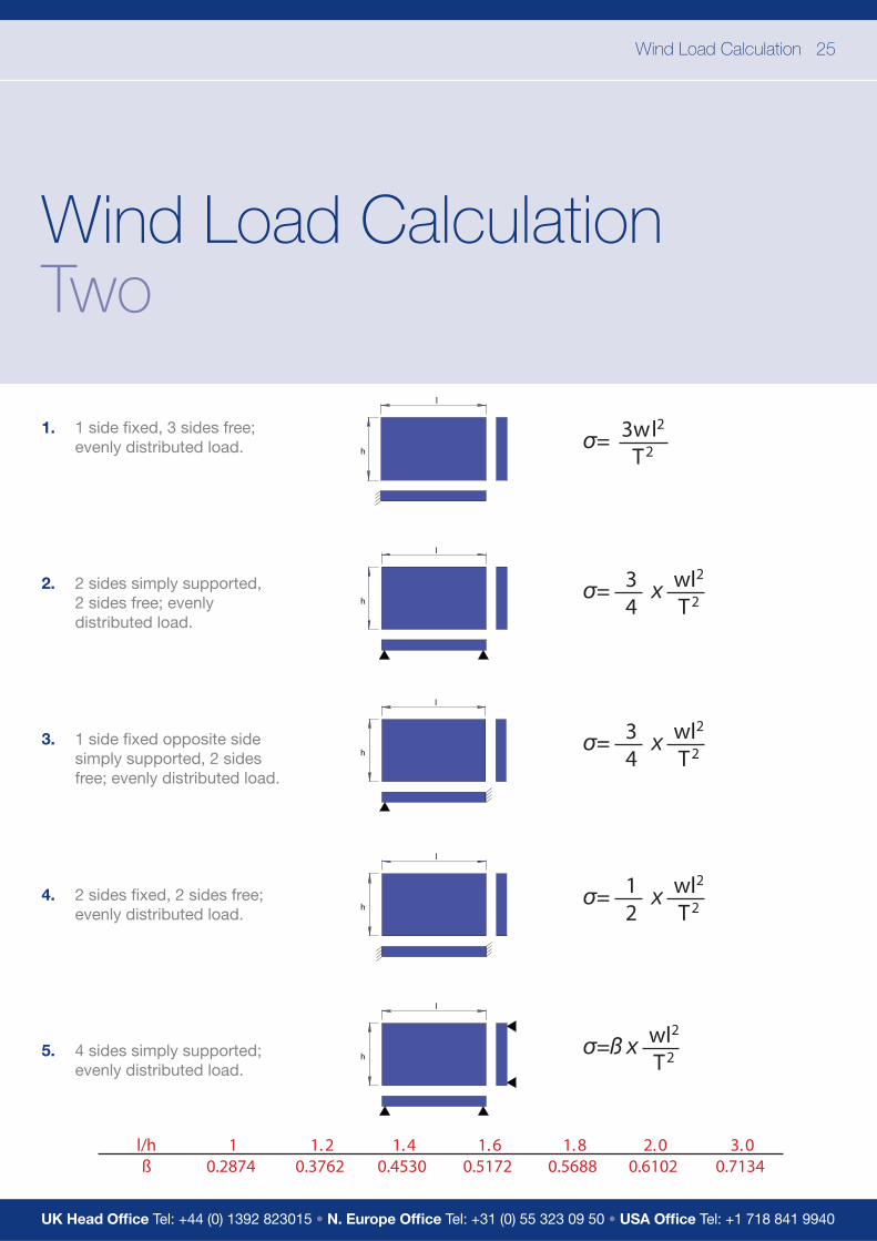
1. 1 side fi xed, 3 sides free; evenly distributed load.
2. 2 sides simply supported, 2 sides free; evenly distributed load.
3. 1 side fi xed opposite side simply supported, 2 sides free; evenly distributed load.
4. 2 sides fi xed, 2 sides free; evenly distributed load.
5. 4 sides simply supported; evenly distributed load.
l/hß
10.2874
1. 20.3762
1. 40.4530
1. 60.5172
1. 80.5688
2. 00.6102
3. 00.7134
3wl2
T2
l
h
wl2
T234
x
l
h
wl2
T234
x
l
h
wl2
T212
x
l
h
wl2
T2x
l
h

26 Wind Load Calculation
a multitude of applications
Wind Load CalculationThree
6. 4 sides fi xed; evenly distributed load.
7. Longer sides fi xed, shorter sides simply supported; evenly distributed load.
8. Longer sides simply supported, shorter sides fi xed; evenly distributed load.
9. 1 longer side fi xed, another longer side free, shorter sides simply supported; evenly distributed load.
10. 1 shorter side free, other sides simply supported; evenly distributed load.
l/hß
10.3087
1. 20.3834
1. 40.4356
1. 60.4680
1. 80.4872
2. 00.4974
l/hß
10.4182
1. 20.4086
1. 40.4860
1. 60.4968
1. 80.4971
2. 00.4973
wl2
T2x
wl2
T2x
l/hß
10.4182
1. 20.5208
1. 40.5988
1. 60.6540
1. 80.6912
2. 00.7146
l/hß
10.714
1. 51.362
21.914
32.568
l/hß
10.67
1. 50.77
20.79
40. 8
wl2
T2x
wl2
T2x
wl2
T2x
l
h
l
h
l
h
l
h
l
h
UK Head Offi ce Tel: +44 (0) 1392 823015 • N. Europe Offi ce Tel: +31 (0) 55 323 09 50 • USA Offi ce Tel: +1 718 841 9940
Wind Load Calculation 27
Wind Load CalculationFour
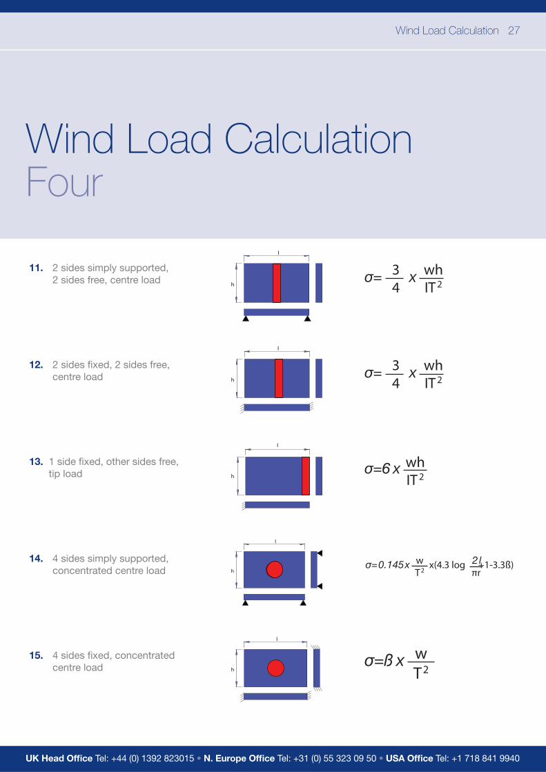
11. 2 sides simply supported, 2 sides free, centre load
12. 2 sides fi xed, 2 sides free, centre load
13. 1 side fi xed, other sides free, tip load
14. 4 sides simply supported, concentrated centre load
15. 4 sides fi xed, concentrated centre load
whIT 2
34
x
whIT 2
34
x
x whIT 2
x wT2
l
h
l
h
l
h
l
h
l
h
x(4.3 log +1-3.3ß)wT2
a multitude of applications
UK Head Offi ceUnit 6, Site 2, Oak Business Units,Thorverton Road, Matford, Exeter,Devon, EX2, 8FS Tel: +44 (0) 1392 823015
Northern Europe Offi ce Tel: +31 (0) 55 323 09 50
USA Offi ceTel: +1 718 841 9940
www.multipaneluk.co.uk