aluminum gantry safety manual - portable gantry cranes · aluminum gantry safety manual all models...
TRANSCRIPT

Aluminum Gantry Safety Manual
All models starting with 2PSB
EC&MW, Inc. 2203 Industrial Way
Elko, NV 89801 Phone 1-888-867-9111 or 1-775-778-9112
Fax 1-866-840-3839 Online Address, Gantries @ AOL.com
www.ecmw.com
We would like to Thank You for purchasing one of our
Aluminum Gantries. If you have any questions or comments about our product please contact us at 1-888-867-9111.

Foreword
This manual has been prepared for the owner and those responsible for the operation of our aluminum gantries. Its purpose, aside from operation, is to promote safety through the use of accepted correct operating and maintenance procedures. Read the safety and maintenance instructions thoroughly before operating and servicing the gantry or any rigging equipment. In order to obtain maximum life and efficiency of your gantry, and to aid in operating and maintaining the gantry with safety, read this manual thoroughly and follow all instructions carefully. The specifications put forth in this manual were in effect at the time of publication. However, owing to EC&MW policy of continuous improvement, changes to these specifications may be made at any time without obligation on the part of EC&MW, Inc. This information and recommendations contained in the publication come from sources believed to be reliable and to represent the best current practice ECMW, Inc. does not intend this manual to be a complete course of instructions on how to use this gantry with safety and does not guarantee or represent that the information is absolutely correct or sufficient. In addition, it cannot be assumed that all acceptable safety measures are listed or that other additional measures are not needed under particular or exceptional circumstances or conditions.

Contents Safety / Warning Instructions Pg. 1 - 4 Top Cap/Receiver Tube I Beam Assembly Pg. 5 Inspection, Maintenance & Testing Pg 6 Gantry Assemble and Height Adjustment Pg 7
Cart Assembly Pg. 8 Warranty Information Pg. 9 Troubleshooting Pg. 10 Gantry Reference Guide Packing List
Page 1
SAFETY INSTRUCTIONS
Read these safety instructions in its entirety before using!
You must understand these instructions and warnings prior to use. If you, as the owner or user, do not understand English, it is your responsibility to have all the instructions and warnings interpreted into your native language for full and total
comprehension. Debe comprender estas instrucciones y advertencias antes de su uso. Si usted, como propietario o usuario, no comprende el inglés, es su responsabilidad tener todas las instrucciones y advertencias interpretadas en su idioma nativo para una comprensión total y completa.
Warning! It is your explicit responsibility to consider all risk factors prior to using this or any rigging device or product. To avoid injury, read and fully
understand this information before using this product. Follow all OSHA and ANSI standards and guidelines. Owner must ensure that all users are trained on
the use of this or any rigging product. Use by untrained persons is not only hazardous but extremely dangerous. Improper use could result in serious injury
or death and or property damage. All rigging products will fail if damaged, abused, misused, overused or improperly maintained.
Never
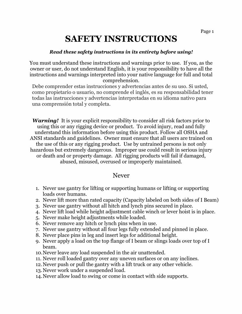
1. Never use gantry for lifting or supporting humans or lifting or supporting
loads over humans. 2. Never lift more than rated capacity (Capacity labeled on both sides of I Beam) 3. Never use gantry without all hitch and lynch pins secured in place. 4. Never lift load while height adjustment cable winch or lever hoist is in place. 5. Never make height adjustments while loaded. 6. Never remove any hitch or lynch pins when in use. 7. Never use gantry without all four legs fully extended and pinned in place. 8. Never place pins in leg and insert legs for additional height. 9. Never apply a load on the top flange of I beam or slings loads over top of I
beam. 10. Never leave any load suspended in the air unattended. 11. Never roll loaded gantry over any uneven surfaces or on any inclines. 12. Never push or pull the gantry with a lift truck or any other vehicle. 13. Never work under a suspended load. 14. Never allow load to swing or come in contact with side supports.

Page 2
15. Never position trolley or hoist assemblies on outside of gantry legs. 16. Never position gantry legs where loaded or unloaded gantry can become
unstable. When in motion or motionless. (Keep legs adequately apart, so gantry will not upset.)
17. Never use any product exhibiting deformities, unusual wear or deterioration. Gantry must be immediately replaced or repaired.
18. Never store gantry where corrosives chemical or solvents are kept. 19. Never force or hurry your work or equipment.
You and your equipment will do better and be safer at the rate for which it was intended.
Always
1. Always remove cable height adjustment winches after adjustment is made. 2. Always verify that all I Beam clamps are positioned correctly, and that the
bolts are torque to the proper specifications:
1/2” 13 thread to 51 ft lb. each or 69 nm.
5/8” 11 thread to 108 ft lb each or 146 nm. Only use EC&MW O.M.E. Clamps
Only use proper sized I beams. Height and flange widths. I Beams are called: S Shapes aka American Standard & Tapered
Flange. 3. Always when moving the loaded gantry push/pull simultaneously on both
gantry legs, not on the load. 4. Always when moving the loaded gantry, keep load as close to the floor as
possible and positioned in the center of the I- beam when possible. 5. Always position: I Beam and Hoist & Trolley directly over center of load before
lifting. 6. Always remove trolley and hoist when assembling or disassembling gantry. 7. Always make certain that the load is not attached to the ground and any
obstacles that may impede lifting have been removed. 8. Always make any adjustments and or repairs in an area where it will have the
least interference with the operation. 9. Always before each use make certain that all operating and safety instructions
for all rigging equipment have been read and fully understood. Note: Operating and safety instructions for other rigging equipment such as hoists, trolleys and slings, you should seek OEM instructions.
10. Always before each use make certain all caution/warning labels are in place and legible.

Page 3
11. Always before each use verify that the rated capacity of the gantry is clearly
marked on each side of the I-Beam. 12. Always keep all visitors a safe distance from work area.
13. Always keep work area clean, floors especially. Cluttered areas invite accidents.
14. Always stay alert:
Watch what you are doing. If using outside (roof tops) note weather conditions.
Use common sense. 15. Always store gantry in a safe and dry area, which will be free from weather and
foreign materials.
Additional Safety Instructions
1. Warning! Gantry will conduct electricity.
Never use gantry where power lines or open circuits are present. Roof top use, note weather conditions for the chance of electrical storms.
2. It shall be the owner’s responsibility to maintain all warnings and instructions and to see that they are intact, as well as legible.
3. All users must know and understand OSHA regulations, ANSI standards and any other relevant regulations.
4. Destroy! Do NOT attempt to repair gantry if exposed to flames/fire or corrosives chemicals, either could have a detrimental effect on the molecular characteristics of the aluminum. Specifically the strength.
5. When moving loaded gantry, observe that all wheels are rolling freely.
Excessive force should never be used when moving gantry.
Rev 1/18
Page 4
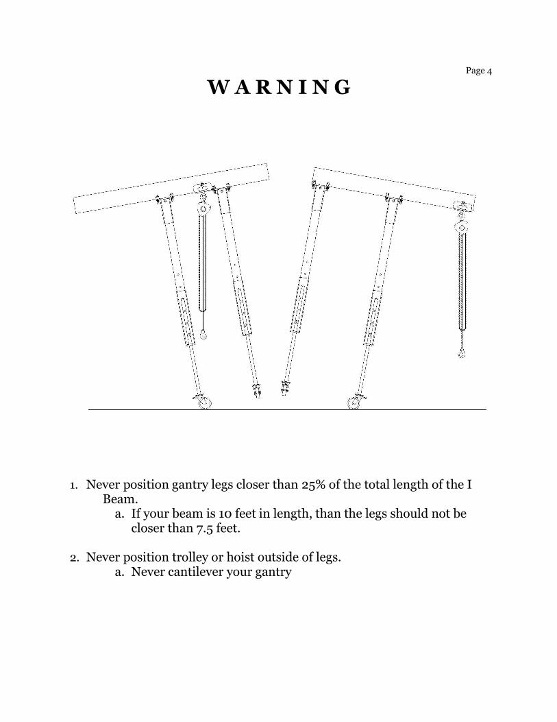
W A R N I N G
1. Never position gantry legs closer than 25% of the total length of the I Beam.
a. If your beam is 10 feet in length, than the legs should not be closer than 7.5 feet.
2. Never position trolley or hoist outside of legs.
a. Never cantilever your gantry
Page 5
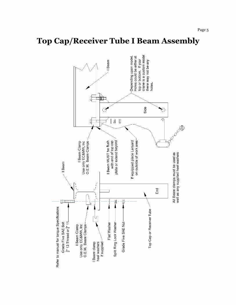
Top Cap/Receiver Tube I Beam Assembly
Page 6
Inspection, Maintenance & Testing
A maintenance schedule should be implemented for your gantry. Intervals are
dependent upon amount of use. We would suggest starting with every 3 months.
1. Before each use: Check that all caster locking pins are in proper working order and all caster mounting hardware are in place and secure.
2. Before each use: Check welds for any signs of stress or cracks. 3. Before each use: Check structure for any signs of deformities/fatigue. 4. Before each use: Check that all mounting hardware holding top caps to I
Beam are positioned correctly and torque to the proper specification. 5. Before each use: Check trolley alinement etc. Refer to O.M.E. Literature. 6. Before each use: Check hoist hook clasps etc. Refer to O.M.E. Literature. 7. Before each use: Check any and all other lifting apparatus such as, nylon
slings, cables etc. for their lifting integrity. Replace immediately if necessary. Do Not Use!
8. Before each use: Check that all warning labels are intact and legible. 9. Check casters to see that they roll freely, grease caster wheels Only when
necessary. “Do Not Over Grease!” 10. Check lynch pins for proper working order. 11. Check the extension tubes and caster extensions as well as all receiver
tubes to see that they are clean. Dirt will impede the performance of your gantry. If necessary clean with soap and water only. Then apply a thin coat of furniture paste wax to female sections of both the bases and top caps.
12. Check load beam. When wear exceeds 10% of the original stock beam, it should be replaced.
13. Destroy! Do NOT attempt to repair gantry if exposed to flames/fire or corrosives chemicals, either could have a detrimental effect on the molecular characteristics of the aluminum. Specifically the strength.
14. Clean gantry with soap and water. Never use cleaning solvents! 15. If gantry is used near coastal communities, salt air can act as a corrosive.
Wash down gantry more frequently with fresh water. 16. Testing: Your new gantry has been designed and constructed to meet or
exceed our interpretation of ANSI B30.17 as well as other principal agencies. A qualified person should be chosen with knowledge pertaining to cranes to perform a load test of no more than 125% of its rated capacity and no less than 100% of its rated capacity, before it is placed into service. For more information regarding this, see the latest edition of ANSI B30.17 for explanation and particulars regarding testing.
O.M.E. Original Manufacture Equipment
Page 7 Gantry Assembly & Height Adjustment
A. The SB models have reversible tubes. Meaning either ends can go into the bases or top caps. This was made purposely to achieve numerous heights if the gantry was to be set up on two different levels. Curbs etc. So check holes spacing’s on the extension tubes before assembly if you planning to use the crane on a flat level surface.
B. First and foremost NEVER force extensions. Both of your gantries extension tubes were tested prior to shipping to ensure a proper fit.
C. Use lift truck when possible to assemble and disassemble unit. Never attempt to assemble or disassemble gantry manually and without at least 2 persons. Smaller length I beams can be done by one person. Think safety first!
1. Insert extension tubes to lowest position into main bases. Attach hitch
pins and lynch pins. 2. Widen lift truck blades completely and place I beam in center of blades.
Note: Lift truck blade width should be of great consideration at this point depending on I beam length. Attach receiver tubes to I beam as shown in diagram on page 6. With top cap/receiver tubes facing down, raise top caps/receiver tubes above extension tube. Lock casters parallel with base and roll main base under top cap/receiver tube and lower blades so as to insert extension tubes. Pin assembly with hitch and lynch pin. While retaining the I Beams weight on lift truck remove height adjustment pin from that base. Carefully raise fork allowing first extension to rise. Then assemble other side as before. NOTE: Take care when lowering fork blades that extension doesn’t bind!
If lift truck is not available follow above procedure with exceptions. Lean base over while workmen raise one of beam onto extension tube. Attach hitch and lynch pins then again rise other side of I beam and roll base underneath and attach hitch and lynch pins
3. Adjusting heights: Extreme care should be taken when using lift truck not to raise extension tubes/I beam so far as to remove them completely.
If trolley and hoist are attached it is best to remove, otherwise secure from moving. Raise the I Beam section first by lifting up on the top cap. Then raise from the base next by lifting up on the extension tube itself. Raise to desired height one hole at a time. When completed attach both hitch pins and lynch pins.
4. Attach trolley and hoist. Refer O.E.M. Manuals 5. To disassemble do the following procedure in reverse.

Page 8
Cart Assembly all models
1. Lock all four-swivel casters in line with base. 2. Stand up one base up on flat level surface. Take the non-Steering cross bar
attach one clip pin to one outside end. 3. Insert the cross bar completely through the bases. 4. Rest that base on the bar. Get the other base and roll it close to the first
one. Take the first base and slide the bar back out 5”, line up second base. 5. Now slide the bar into the second base. Adjust the bases so that the bar
comes completely out the other side of base #2. Attack all four pins. 6. Take steering cross bar and insert into one of the bases by, lifting up one
base approximately 6” in the air. Insert cross bar all the way to handle collar. Now lower and slide cross bar across into base #2. Attach all four clip pins.
7. Set I Beam on both cross bars X Tubes etc. per drawing above. Attach bungee cords supplied to cross bars. Put one on each bar over I beam.
8. Take chain from hoist and drop into extension tube receiver. Hook chain hoist to end of receiver.
9. Hook steering handle on steering cross bar. Hook handle over thin side, and then slide over handle collar. This way handle will not fall off when being pulled.
10. Unlock the two swivel casters on the steering end ONLY. You are now ready to roll.
Page 9
Warranty EC&MW, Inc. warrants to the original buyer that this product shall be free from all defects in material or workmanship for a period of 10 years from date of purchase. This warranty is the only written or express warranty given by EC&MW, Inc. This warranty does not apply to any product, which has been subjected to Abuse, Misuse, Negligence, Modification, Overuse, Accident or Normal Wear. We are also not responsible for cost of inconvenience or damage due to product failure. EC&MW, Inc. cannot be responsible for any unlawful sale(s) by unlawful dealers and or any other 3rd party resellers. This includes ALL resale’s by either online or yard auctions. This warranty is not transferable and is valid only for the original buyer and does not include any subsequent resales. In no event shall EC&MW, Inc. be liable for incidental or consequential damages. Upon its return (Freight Prepaid) to our factory, EC&MW, Inc. will if found defective, refund, repair or replace any part or the entire unit, with one of it or like model. Other manufactures warranties will apply and supersede any warranty given by ECMW, Inc. For those warranties and repairs you must contact the individual manufactures directly. Any alterations or misuse of this product will void all warranties and liabilities. Customer assumes all liability and risks resulting from the use of this product. This warranty gives you specific legal rights and you may have other legal rights, which vary from state to state. Some states do not allow limitations on how long an implied warranty lasts, or allow the exclusion or limitations of incidental or consequential damages, so the above limitations or exclusions may not apply to you. Some states do not allow limitations on how long an implied warranty lasts, or allow the exclusion or limitations of incidental or consequential damages, so the above limitations or exclusions may not apply to you.

Page 10
Troubleshooting
EC&MW, Inc. strive so that your gantry is free of all defects in material and workmanship. All of our gantries are inspected before they are shipped. If you continue to have trouble, please read the following instructions before calling for assistance. 775-778-9112 If hitch pins do not line up: Make sure you have extension tubes
in right direction.
Check that no dirt or debris has fallen into receiver tubes.
Check that no fragments are stuck to the ends of the extension tubes.
Make sure you’re using pins supplied with gantry. Make sure the proper pin is used. Some models use 2 different dia. pins
Some gantry models are designed so that the load is to be supported on
pins. Lift up extension tubes or main beam about 1/8” to line up holes. Hitch pins fall out: Check to see that lynch pin has not been lost and is seated properly. Swivel caster won’t swivel: See if caster has been damaged. Grease caster.
Extension tubes bind when Check to see that burrs have not Raising and lowering formed on extension tubes.
Carefully file or sand out burrs. Apply and thin coat of furniture paste
wax to female sections.

Gantry Reference Guide

Packing List “2PSB” Models
Date_________________________
Gantry Model # _____________ Serial # ___________
Base Model #_____________ Serial # ___________
I Beam Model #_____________ Serial # ___________ Two Bases with casters, hitch & lynch pins attached. ________ Two extension tubes. ________ Two receiver tubes with hitch & lynch pins attached. ________ Eight bolts, nuts, lock, flat washers & Beam Clamps. ________ One safety instructions manual. ________
Optional One steering handle. ________
Optional One cross bar (non steering) ________
Optional One cross bar steering. ________ Optional Eight clip pins. ________ Optional Two bungee cords. ________ Safety labels #__________ attached. Hoist ____ ___Ton Trolley _____ ___Ton Nylon slings _____Ft.________ Nylon sings _____Ft.________ Comments: _______________________________________________ ____________________________________________________________ ____________________________________________________________ Packaged By:____________________________________________